In the present section, we will refer to some of the most characteristic performance measurements performed initially on the first LESS-1 engine prototype and, next, to similar performance measurements on the final LESS-2 engine prototype.
Among the main purposes of performance measurements was the recording of the engine torque and the fuel consumption, as well as the pollutant emissions for different engine operating speeds. In addition, the break power and brake engine efficiency were calculated under the same operating conditions. One additional purpose was the initial estimation of the engine reliability under a variety of operating conditions.
3.2.1. Less-1 Prototype Measurements
The measurements of the LESS-1 engine prototype were performed under the following operating parameters and operating conditions:
Carburetor nozzle of 0.8 mm and WOT engine operation;
Carburetor nozzle of 1.1 mm and idle engine operation;
Carburetor nozzle of 1.1 mm and WOT engine operation;
Carburetor nozzle of 1.25 mm and idle engine operation.
The results of the most important measured and calculated engine variables for each of the previous cases are summarized below.
The results from the most important performance variables of the LESS-1 prototype engine for a carburetor nozzle of 0.8 mm-and WOT engine operation are presented in
Table 3.
The indicated torque corresponding to the combustion of the two chambers is 28.3 Nm, while the corresponding indicated power produced through the combustion is 5.65 kW. It is noted that, although an indicated torque of 28.3 Nm is produced, the brake torque is only 4.96 Nm, and the corresponding brake power is only 0.99 kW (from the indicated power of 5.65 kW). These figures lead to a value of mechanical efficiency of 17.5%, which is quite low compared with the mechanical efficiency of a modern high-performance engine, which stands in the range of 80–90%.
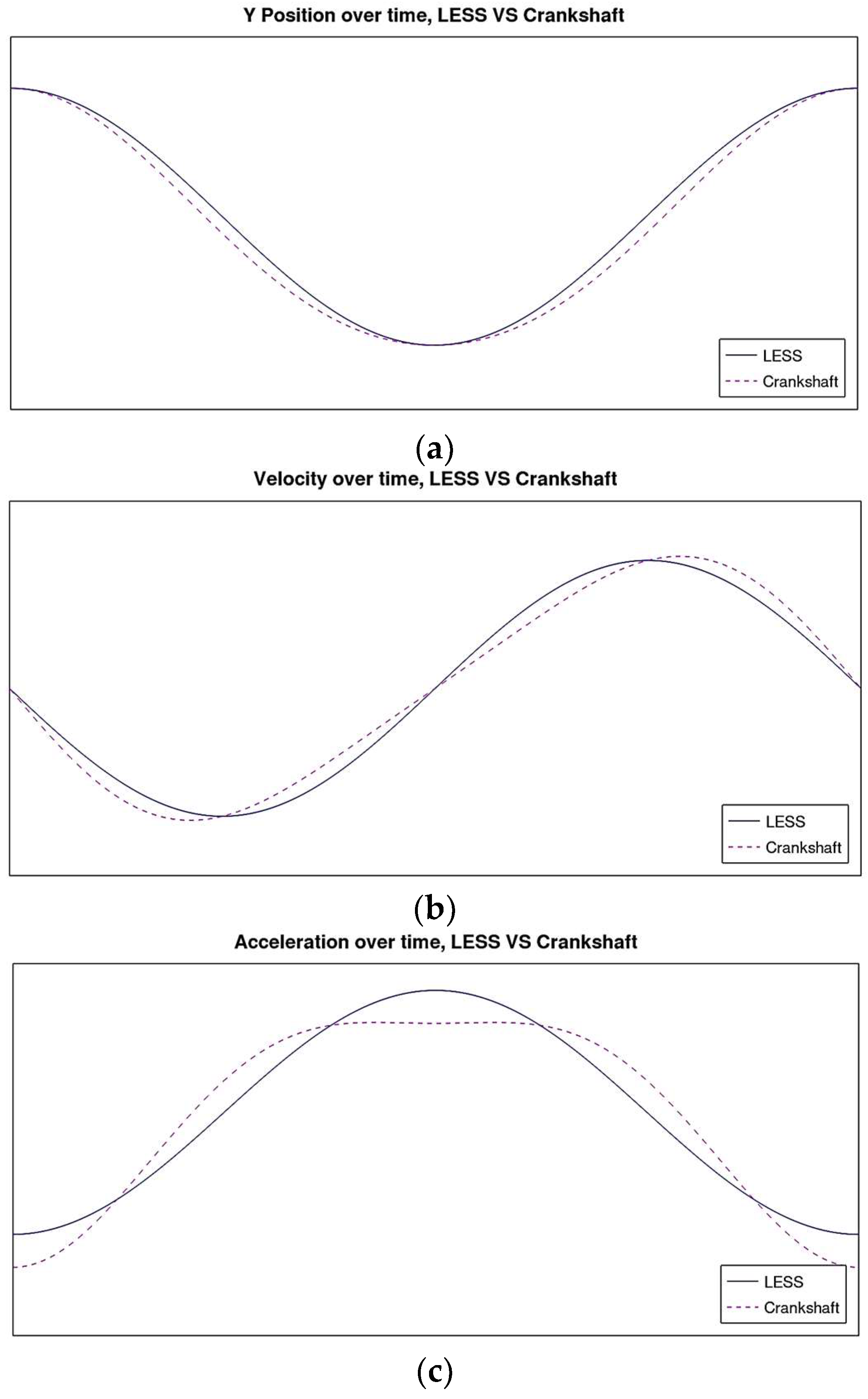
It should be mentioned that the torque measured at the output of the engine is reduced to the corresponding value of a crank engine, due to the aforementioned difference that the LESS mechanism has in relation to a conventional crank mechanism, so that we can compare similar values.
Therefore, the low performance of the engine mechanical efficiency reveals that the engine’s tribological losses, and the resulting component wear, are significantly increased, and strongly contribute to the engine’s poor performance. As a result, in the subsequent stages, special care should definitely be taken to solve this problem, and a thorough analysis of the various subsystems and, especially, of the LESS mechanism, is necessary to perform. Based on the results of this analysis, engine design optimization is necessary, in order to reduce the problem, and improve the mechanical efficiency.
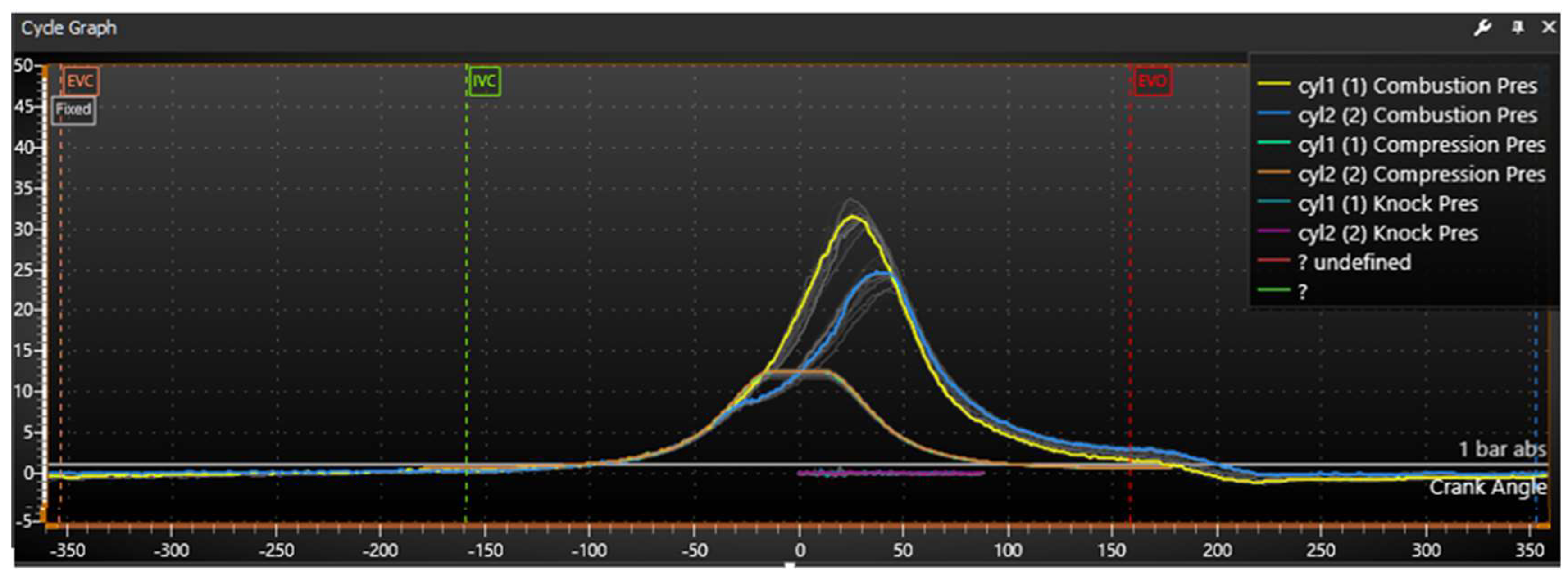
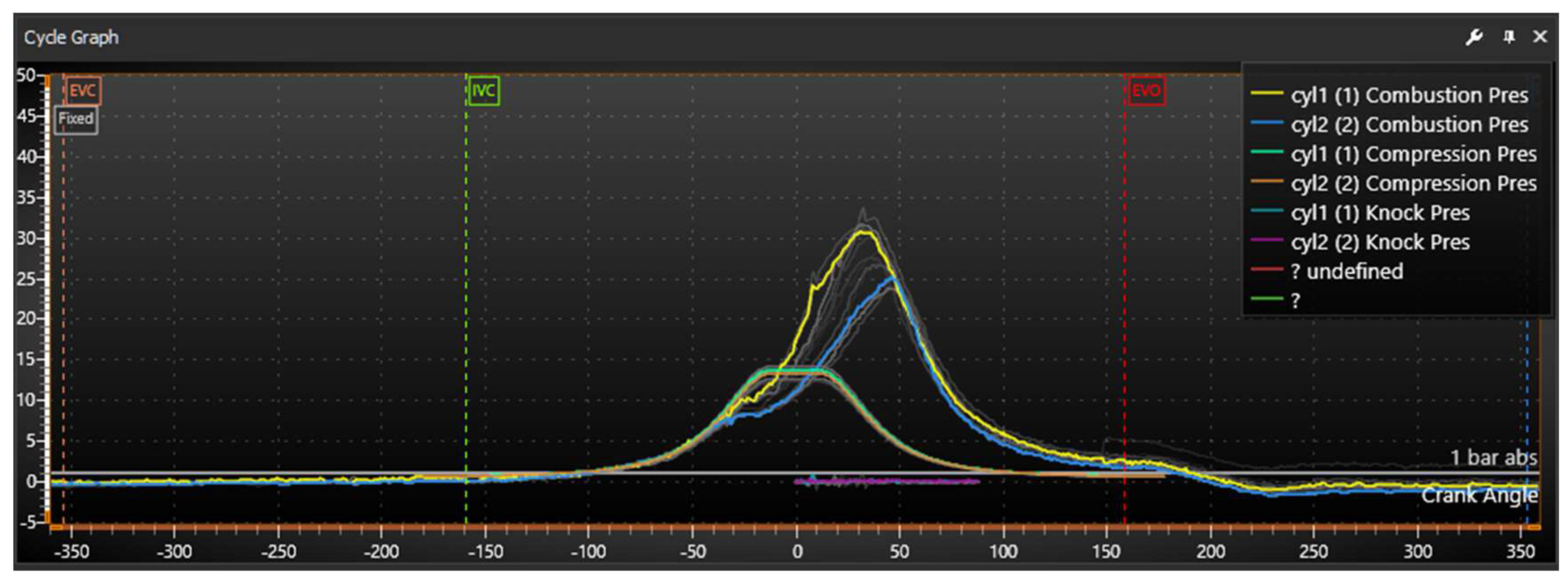
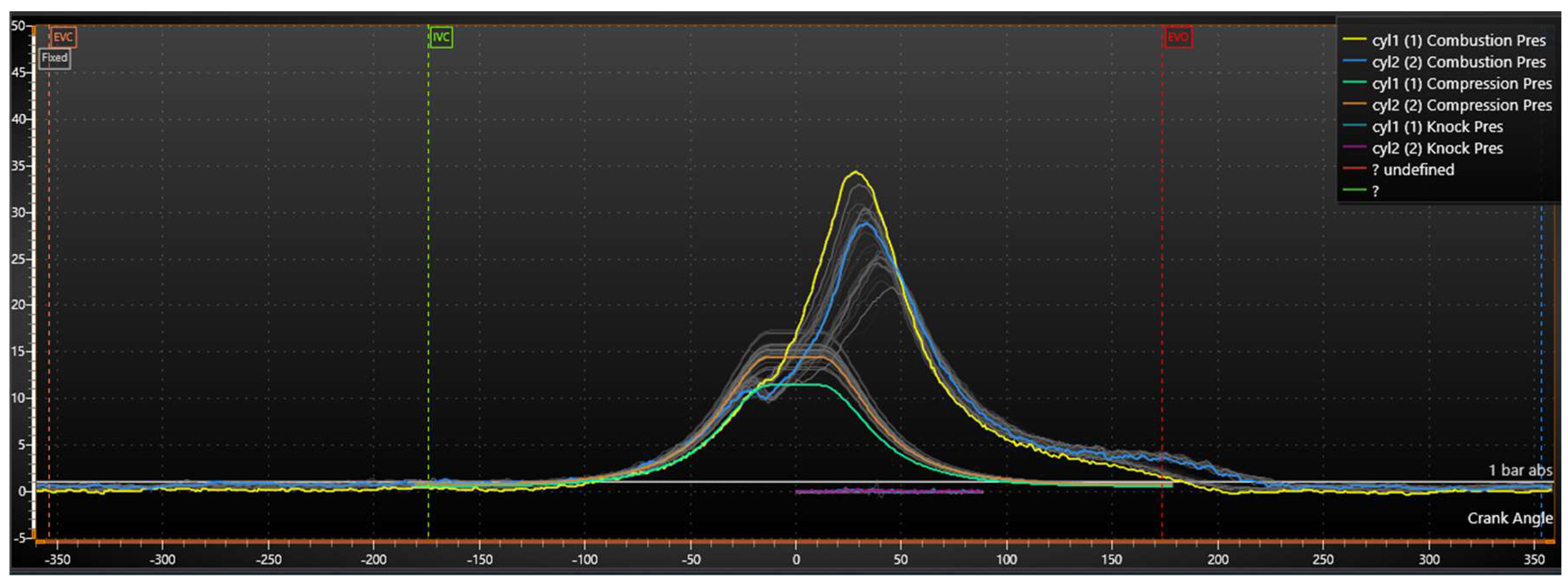
Figure 27 presents the variation in the cylinder pressure during an engine cycle for a carburetor nozzle of 0.8 mm, and WOT engine operation.
In
Figure 27, we present the pressure of the combustion inside cylinder A (yellow line) and cylinder B (blue line), the corresponding pressure variation that would exist without combustion (motoring, the green and orange lines, respectively for A and B) and, finally, the indication of possible auto-ignition or pre-ignition (knock pressure lines).
In the present and also in the succeeding figures of cylinder pressure variation a series of grey lines is also presented. These lines display the variation of combustion pressure during a number of succeeding engine cycles. They provide a clear indication of combustion instability inside each of the two engine cylinders under the specific operating condition.
It is noted that there is a significant difference between the pressure curves of cylinders A and B. This result is a confirmation that the engine in its present stage of development is undergoing problematic combustion, which is due to problems in the ignition control and ignition timing system, as well as in the fuel delivery and injection system.
- b.
Carburetor nozzle of 1.1 mm and idle engine operation
In a second series of measurements, the initial carburetor nozzle was replaced with one of 1.1 mm, with the aim of providing more fuel to the mixture, as cylinder B, in particular, was running lean and, due to the variation, there were cycles where its combustion was significantly unstable, or even where there was no combustion at all.
After the nozzle replacement, we observed a clear reduction in the variation in the operating speed, with the average speed being 1300 rpm and, generally, ranging from 1260to 1340 rpm, while the stable operation and measurement of the engine at idle was possible under the present configuration.
In the following
Table 4, we present the results from the most important performance variables of the LESS-1 prototype engine for the case of a carburetor nozzle of 1.1 mm, and idle engine operation.
It is observed that, with the new configuration, the results are improved; however, the mechanical efficiency, despite its improvement, still remains very low, as should be expected. It should be noted that, in this case, the engine operation is in idle; therefore, its performance is expected to deteriorate in comparison with its WOT operation.
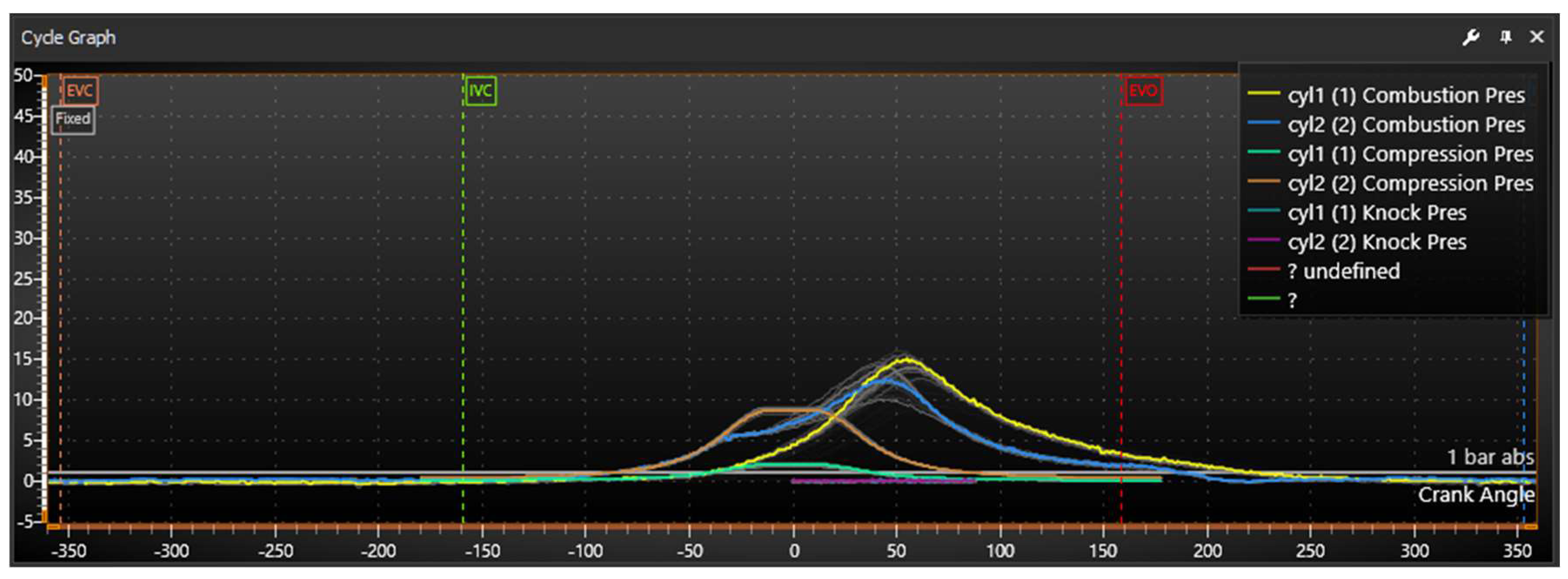
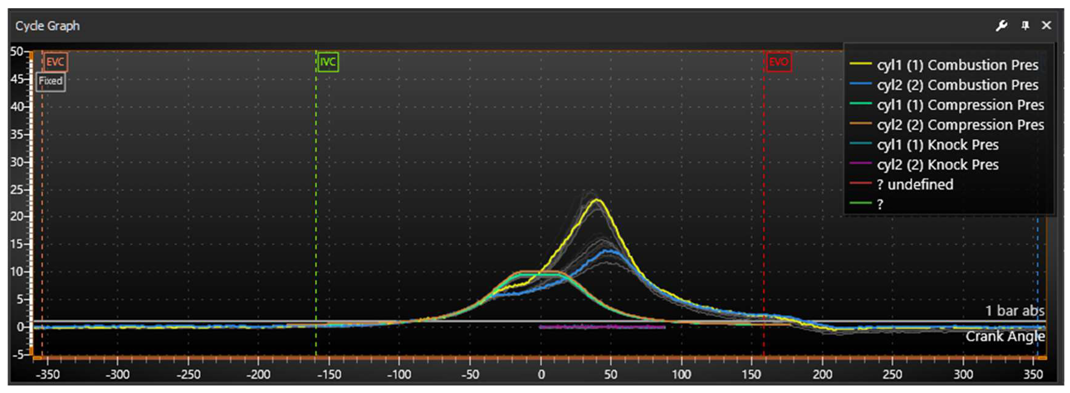
The respective cylinder pressure variation for the present case is presented in
Figure 28. A relatively low maximum pressure is observed in both engine cylinders, which is actually reached relatively late. The pressure differences between the two cylinders remain significant, and this is due to the large difference in the air–fuel ratio between the two cylinders.
- c.
Carburetor nozzle of 1.1 mm and WOT engine operation
In the final stage, the performance measurements were accomplished using the same carburetor nozzle of 1.1 mm, at a WOT operating condition. The engine speed, in this case, was raised, at 2000 rpm.
Table 5, below presents the results from the most important performance variables for the present case of a carburetor nozzle of 1.1 mm, while engine was operated under a WOT condition.
We observe that the indicated torque increases at 29.9 Nm compared with the case with the 0.8 mm nozzle, where a value of 28.3 Nm was accomplished. However, as in the two previous cases, the friction losses remain high, as was expected, due to the limitations of the proposed new kinematic system. As a result, the engine’s mechanical efficiency continues to hover at a low value of 16.39%.
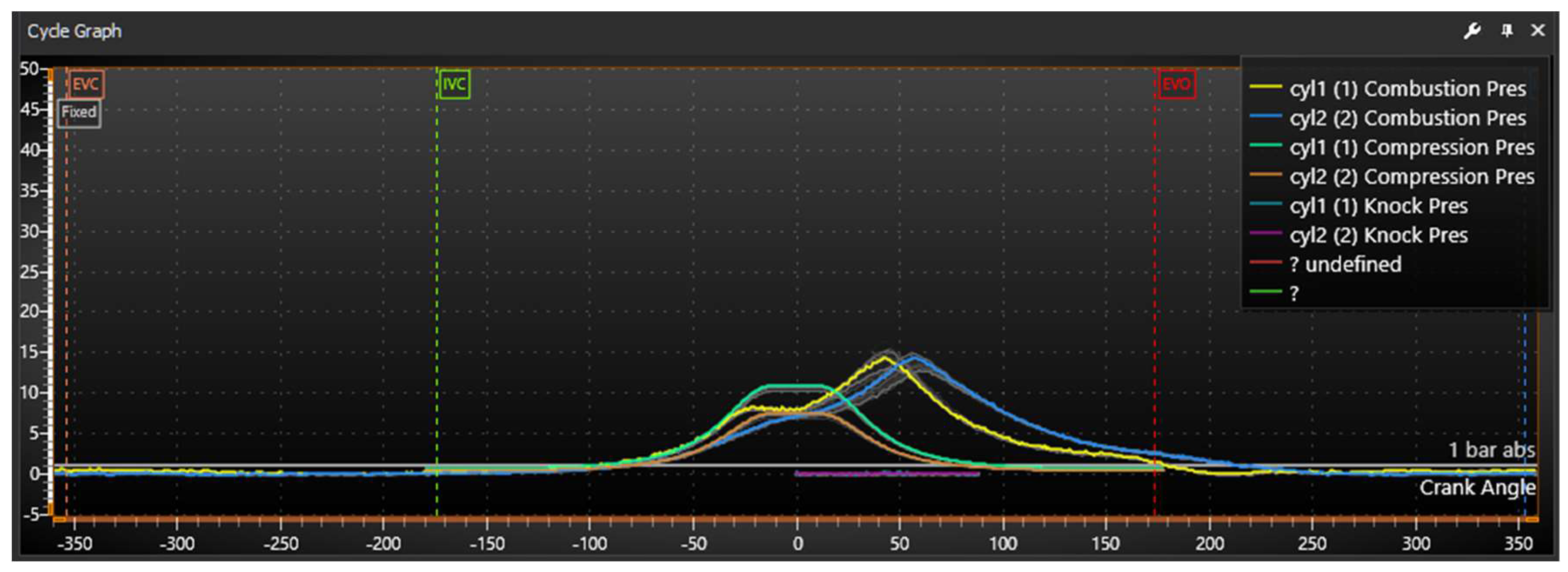
The cylinder pressure variation inside both cylinders for the present operating condition is presented in
Figure 29.
It is observed that the combustion in cylinder A is noticeably better, as a result of the extra fuel supply. The combustion in cylinder B remains relatively poor, as no significant pressure is developed and, as a result the indicated work in this cylinder is reduced.
- d.
Carburetor nozzle of 1.25 mm and idle engine operation
In the final stage of measurements for the LESS-1 prototype, the carburetor nozzle diameter was increased to 1.25 mm as, in several cases in the previous measurements, it appeared that the air-fuel ratio was still above 1 and, therefore, combustion was not progressing satisfactorily.
Additionally, in the present case, multiple changes were made to the nozzle control and its needle adjustment, as well as at the air bypass and idle air-fuel ratio adjustment, in an effort to achieve an optimum engine performance.
In
Table 6, we present the results from the most important performance variables of the LESS-1 prototype engine for the case of a carburetor nozzle of 1.25 mm, and idle engine operation.
Again, it is observed that, with the new configuration, the results are improved; however, the mechanical efficiency, despite its improvement, still remains very low, as should be expected.
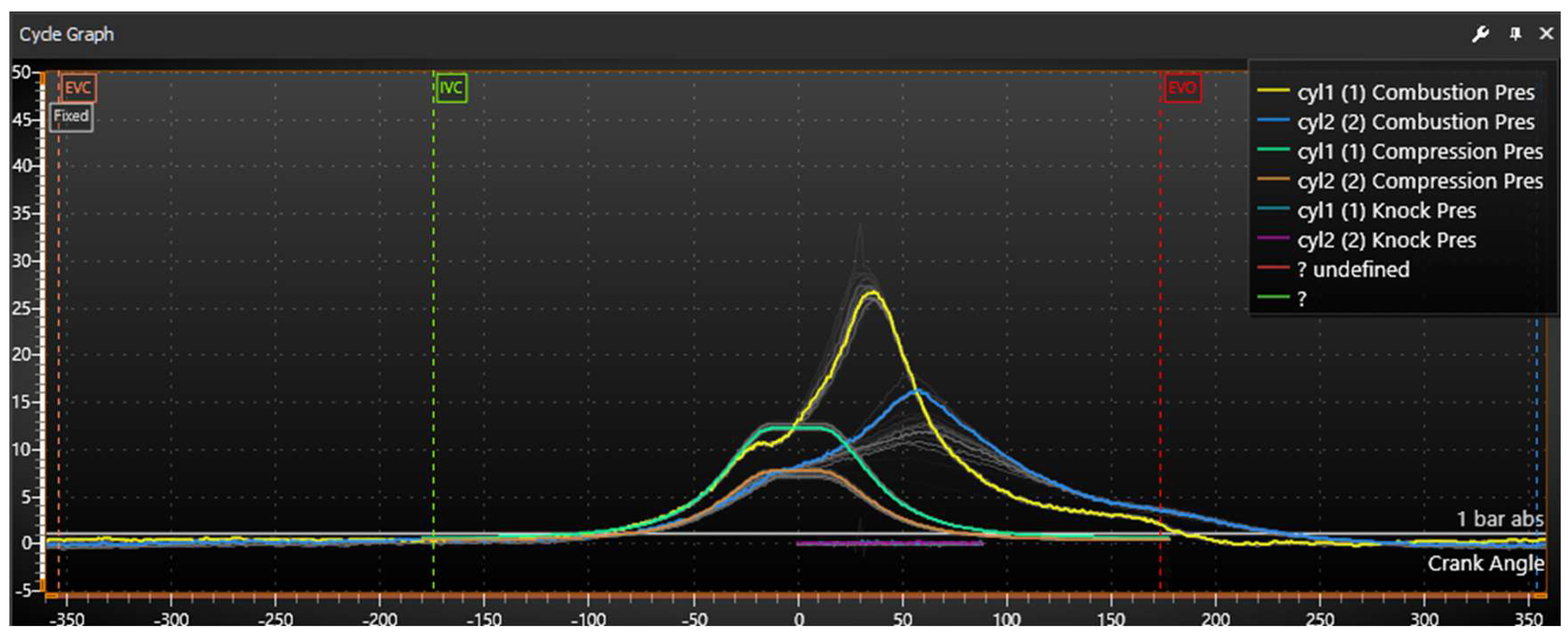
The cylinder pressure variation inside both cylinders for the present operating condition is presented in
Figure 30. Again, a reduced and delayed combustion is observed in cylinder B, which is present more intensively in the present case.
In this case, cylinder B works—in general—even in areas where its air-fuel ratio exceeds 1; therefore, the combustion takes place with a lean mixture. This is also a reasonable explanation as to why the work is less in this cylinder, compared with cylinder A.
3.2.3. LESS-2 Prototype Measurements
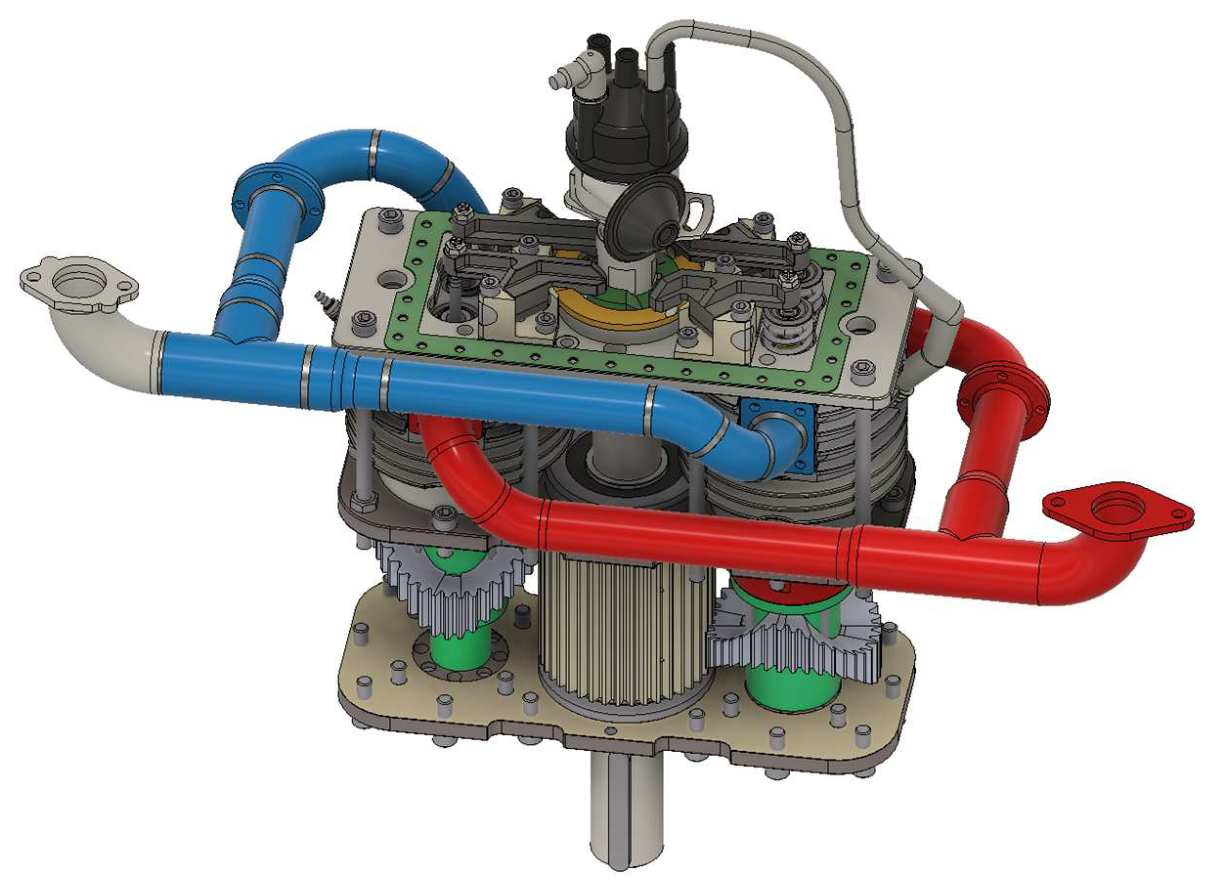
Based on the results of theoretical calculations and the experimental measurement campaign with the LESS-1 prototype, the LESS-2 engine prototype was developed and manufactured. Important changes and improvements were applied to the LESS-2. These included fuel injectors, new intake pipes, connecting circuits, etc.
The updated engine configuration presents its idle at 700 rpm (the actual output shaft speed, or “LESS” speed), which is completely compatible with the idle speed of a traditional combustion engine, which usually lies between 800 and 1000 rpm. As mentioned previously, the LESS mechanism operates at half the speed of a crankshaft mechanism and, due to this, the resulting measurements have been reduced to the corresponding crankshaft revolutions, so, for the purposes of analysis and comparison, the engine revolutions are considered at 1400 rpm.
Accordingly, with a full fuel mixture supply, i.e., with a fully open intake throttle, and corresponding fuel supply, the engine crank equivalent varied between 1300 and 2300 rpm, depending on its load. At engine speeds lower than 1500 rpm, we observed dynamic phenomena, mainly engine speed fluctuation. Due to this observation, the lower operating speed for a full engine load was considered at 1500 rpm. A similar speed instability was observed for speed values above 2100 rpm, resulting in an uneven operation. This was considered to be affected by the high percentage of mechanical losses, as the engine speed was increased to higher values. Therefore, the upper speed limit during the second measurement campaign was considered to be 2000 rpm.
The measurements with the LESS-2 engine prototype were performed under the following operating parameters and operating conditions:
1400 rpm–idle engine operation;
1500 rpm–WOT engine operation;
2000 rpm–WOT engine operation.
The results of the most important measured and calculated engine variables for each of the previous cases are summarized below. In the case of the LESS-2 prototype, we will additionally present, in the following subsections, the results from the experimental measurements for the most important engine emissions.
In
Table 7, we present the results from the most important performance variables of the LESS-2 engine for the case of 1400 rpm speed, and idle engine operation.
It is observed that the mechanical efficiency remains quite low, as in the case of the LESS-1 prototype, and this is expected, as it is mainly due to frictional losses in the new kinematic system. An improved design is necessary in the next stage of engine development in order to overcome this deficiency, and increase engine performance.
The cylinder pressure variation inside both cylinders for the present operating condition is presented in
Figure 31. We observe the relatively low maximum pressure in the cylinder is actually reached relatively late, as a result of the incomplete filling of the engine cylinder with the air-fuel mixture, even after the improvements applied in the present engine version.
On the other hand, it should be mentioned that, with the improved version of the LESS-2, the differences between cylinders A and B are significantly reduced in the present operating condition, and we have the possibility of achieving the stoichiometric ratio in both cylinders.
Table 8 presents the results from the experimental measurements for the most important engine-out emissions.
It is observed that the figures for the LESS-2 engine emissions are comparable with those of an SI engine with the current technology and, in the case of HC, the value is even below that emitted from a modern SI combustion engine. The last observation allows the flexibility to achieve a better fuel consumption and increase the engine efficiency, through optimizing the values of the engine parameters, and mainly those of the fuel injection system.
- b.
1500 rpm–WOT engine operation
Initially, it was observed that, under the present engine operating condition, speed variation almost vanished during the experimental measurements.
Table 9 presents the results for the most important performance variables of the LESS-2 engine for the present case of 1500 rpm speed and WOT engine operation.
The cylinder pressure variation inside both cylinders for the present operating condition is presented in
Figure 32. The maximum combustion pressure is increased in comparison with the results for the LESS-1 under WOT operation. However, there is a significant difference in the pressure variation between cylinders A and B. this difference could be explained via a corresponding difference in the cylinder mass flow and volumetric efficiency, which, despite the improvements still exists under WOT operation in the LESS-2 prototype.
Table 10 presents the results from the experimental measurements for the most important engine-out emissions.
It is, again, observed that the figures for the LESS-2 engine emissions and, especially, that of HC are comparable with, or even below, those of an SI combustion engine with the current technology. An exception in the present case is the value of CO, which stands above that expected from a conventional modern SI engine. This result can be controlled via modifying and optimizing the parameters of the fuel injection system to obtain an acceptable CO value.
- c.
2000 rpm–WOT engine operation
Table 11 presents the results from the most important performance variables of the LESS-2 engine for the present case of 2000 rpm speed, and WOT engine operation.
The cylinder pressure variation inside both cylinders for the present operating condition is presented in
Figure 33. It is observed that, in the present operating condition, the pressure variation presents only a slight difference between the two cylinders. Both the maximum combustion pressure, and the phasing of pressure variation between the two cylinders, are largely improved. It is evident that, in the current operating condition, the mass flow and volumetric efficiency are almost identical between the two cylinders. As a result, the air—fuel ratio is almost stoichiometric at 1.0, and the speed variation is almost at zero level.
The improvement in cylinder charge filling under 2000 rpm and WOT operation, in comparison to the result under 1500 rpm, is explained through consideration of the dynamic flow phenomena existing during the gas-exchange process in combustion engines. It is obvious that the inlet and exhaust engine manifold have to be redesigned in a future stage in the improvement of the engine, in order to secure a uniform cylinder filling and emptying process in the whole engine speed operating range.
Table 12 presents the results from the experimental measurements for the most important engine-out emissions.
It is, again, observed that the figures of the LESS-2 engine emissions and, especially, that of HC are comparable with, or well below, those of an SI combustion engine with the current technology. This result is confirmed via the findings of the theoretical simulation, which revealed that the engine combustion with the specific parameter settings is optimum under higher values of engine speed and, as a result, lower values of emitted HC are expected.


