Abstract
In order to maintain the quality of construction for nearly zero energy buildings and to reduce the pressure on construction workers with the addition of the need for faster and simpler structures, the use of cavity-insulated LSF (lightweight steel frame) panels is increasing. Requirements for performance quality, quality of life, and low energy consumption have led to the need for closer examination of heat transfer through building elements. Due to the impact on increased heat losses, thermal bridges can cause structural damage due to the increased risk of water vapor condensation on the interior surface. In this paper, numerical heat transfer analysis with the optimization of thermal bridges for LSF cavity insulated walls was made in order to reduce the overall transmission heat losses. The effects of different cavity insulation materials (mineral wool and polyurethane foam) on overall heat transferred through the building elements were analyzed. Additionally, in order to reduce the effect of thermal bridges caused by the steel frame structure, the PVC spacers between the steel and sheathing panels are introduced into calculation models. Lastly, additional layers of insulation were added on the internal and external sides of the LFS panels in order to minimize the effect of thermal bridges and maximize air tightness. Combinations of all three setups were made for wall–window, ceiling–wall, wall–floor joints for the numerical calculation. For each setup, the temperature distribution and overall heat transferred through the building elements were calculated. Different thermal bridge designs have a significant influence on the overall heat transfer, and by choosing the optimal design, the transmission heat losses can be reduced by up to 67%.
1. Introduction
In recent decades, the growing awareness of sustainability and the need for energy-efficient buildings have led to the development of the concept of nearly-zero energy building (nZEB). In order to meet the high demands for performance quality, indoor air quality, and minimal energy consumption, the construction industry is looking for innovative solutions that enable faster and simpler construction without compromising the quality of works.
In this context, LSF (Light Steel Frame) panels are increasingly being used in the construction of nZEBs [1,2]. LSF panels are structural load-bearing and non-load-bearing elements made of light steel frames, which are assembled on the construction site and are mostly connected with a bolt connection. After assembling the frame, thermal insulation is installed between the frames of the load-bearing structure, which is then closed within the sheathing panels installed on both sides of the steel structure. These panels offer a number of advantages, including high precision works and repeatability, faster installation, and excellent thermal and sound insulation characteristics compared to the performance of classic buildings made of reinforced concrete or bricks [1].
One of the key challenges in the construction of nZEBs is the design of transmission heat losses [3]. High requirements for energy efficiency require careful study and optimization of the thermal performance of building elements. The study of heat transfer through LSF panels, including heat transfer through joints with other elements, has become essential to ensure the quality of construction and indoor air quality in nZEBs [4]. The increased heat transfer affects the higher consumption of energy for heating and cooling, but during the winter months, it can also cause construction damage. Increased heat flow in places of increased heat transfer on the building envelope (i.e., thermal bridges) will result in a lower surface temperature on the interior surface in the heating period, and if the surface temperature falls below the dew point temperature, water vapor will condense and thus change the properties of the building material, creating conditions for the growth of fungi and mold and, if left untreated, corrosion.
The aim of this paper is to investigate in more detail the heat transfer through LSF panels and analyze their thermal characteristics. Numerical calculations were carried out to analyze the parameters that affect the thermal transmittance (-value) of LSF panels and identify the materials that can improve the thermal properties of the LSF panels.
Among the biggest advantages of prefabricated LSF panels is the construction time compared to concrete and masonry structures [2]. Construction time is especially important in scenarios after a natural disaster that affects a large number of people, such as an earthquake or flood. In these cases, it is necessary to provide sanitary living conditions to a large number of people in a short period of time. Prefabricated construction enables fast and high-quality construction with minimal interventions on the construction site, and it can be not only a temporary but even a permanent solution.
Recent earthquakes in Croatia destroyed or severely damaged many family homes, historic buildings, and essential facilities, such as hospitals, schools, roads, and bridges [5]. With many families forced out of their homes, the need for quick and effective structures emerged.
Prefabricated building elements have many advantages when compared to traditional building styles [6,7,8]. In areas affected by earthquakes, workforce shortage problems were present even before the earthquake, so making new temporary or permanent housing is a big challenge [9]. Request for simple and fast building construction must be accomplished. Solution is found in prefabricated elements such as LSF walls, which can be made in a factory to provide controlled conditions for manufacturing prefabricated elements that can be easily transported to the construction site. When compared to traditional building style, prefabricated elements made in a factory require less skilled workers for manufacturing elements and less skilled workers for building construction. With standardized element layers and dimensions, the need for fast manufacturing can be more easily obtained [6,7,8].
CFS (Cold-Formed Steel) is a widely used building material in the construction industry due to its numerous benefits compared to other materials used for the same purposes [2]. As its popularity grows, it is becoming recognized as a sustainable modern building material [10].
LSF wall is usually made of three parts: steel frame structure (CFS profiles), sheathing panels (gypsum fiberboard, gypsum plasterboard or OSB (Oriented strand board) as internal and external sheathing), and insulation layers [1].
LSF walls have some drawbacks in regard to thermal properties, such as high thermal conductivity and heat accumulation, when compared to concrete walls. Steel is a much better heat conductor, which results in worse thermal performance of the buildings when compared to concrete or brick building elements [11]. Nevertheless, LSF has a high load-to-weight ratio, but because LSF panels contain relatively high amounts of steel, they have more problems related to thermal bridging.
According to [1], there are three types of LSF structures. They differ according to the arrangement of thermal insulation around the steel studs (Figure 1).

Figure 1.
Types of LSF structures. (a) Cold frame construction, (b) warm frame construction, (c) hybrid frame construction.
If an LSF panel is breached for the purposes of making electrical installations, pipes, etc., air tightness might be compromised [2] and thus violate nZEB principles and air quality in buildings. Buildings in warm climates have less negative impacts on energy compromises caused by air infiltrations [12]. A research gap has been noticed regarding the experimental indoor thermal environments and thermal comfort in LSF buildings [13].
Air tightness problems with LSF panels observed in [1] suggest introducing the installation layer on the internal side of the wall with two purposes: (1) enabling minimal penetrations of air-tight membrane and (2) easier access to installations.
When thermal performance is mentioned, it is referred to as a building’s capability to consume the least possible amount of energy for heating and cooling without compromising the thermal comfort of its residents. An essential aspect of achieving optimal thermal performance of the LSF structures is minimizing the thermal bridges due to the high thermal conductivity of steel in LSF elements [14].
There are many studies that focus on the thermal performance of LSF constructions [1,15,16,17], but most of them focus on mineral wool as a cavity filling. Change in cavity insulation materials can change the behavior of LFS construction and modify hygrothermal performance. There is a significant difference between the thermally homogenous and heterogeneous layers of a building’s thermal envelope concerning heat loss. The presence of studs and thermal insulation plays a crucial role in calculating the building’s energy performance [18].
Due to its low mechanical resistance, LSF and its cavity insulation have to be protected with metallic or non-metallic sheathing. Non-metallic sheathing is used more often than metallic. However, optimizing details has to be brought to attention as non-metallic sheathing is mostly produced in fixed dimensions, with a length that is rarely greater than 3.5 m [19].
2. KLIK Panel
Based on the example of LSF panels with a combination of prefabricated construction, a composite lightweight panel with an integrated load-bearing structure (hereinafter referred to as KLIK panel) was designed (Figure 2a,b). It has an LSF load-bearing structure on which the sheathing panels are attached. There are several configurations related to the number of sheathing boards. The configuration includes gypsum fiber boards, where two or three sheathing boards can be selected on both sides. The difference in configurations is primarily related to fire resistance and soundproofing. Polyurethane (PUR) foam is injected into the cavities between the steel structure and sheathing panels. During production, the sheathing panels serve as a mold so that the PUR foam remains within the desired dimensions, and after the installation of the PUR foam, their primary task is to protect the load-bearing structure and filling from external influences, such as fire or water.

Figure 2.
KLIK panel. (a) KLIK panel, (b) 3D model, (c) steel stud without spacers.
The load-bearing structure consists of horizontal and vertical steel studs. Diagonal steel studs can also be added if structural design requires it. The dimensions of C studs are 89 × 42 × 10 × 1.0 mm (Figure 2c). The horizontal spacing of the steel studs is 544 mm, and the vertical spacing is 655 mm. KLIK panels are intended for ground-floor houses. While examining the building’s envelope, several characteristic construction details were identified as thermal bridges, such as: window-to-wall connection, wall-to-roof connection, and wall-to-floor connection.
3. The Case Study
This paper’s case study can be divided into three segments:
- (a)
- A comparison of overall heat transferred through the building elements (L2D) between two types of panels. The cavity insulation of the most commonly used LSF panels is made of mineral wool (MW), while the KLIK panels’ cavity insulation is made of PUR foam. The difference in thermal conductivity (λ) of cavity insulation material results in different L2D.
- (b)
- Impact of steel studs on L2D. In this study, there are three types of models with respect to steel studs: a type without steel studs, steel studs in direct contact with sheathing boards, and steel studs with spacers. Types of steel studs’ performance have an impact on linear thermal bridge coefficient (ψ-value) caused by the high thermal conductivity of steel studs. ψ-value has a direct impact on L2D.
- (c)
- Comparison of L2D between basic panel (cavity insulation with sheathing boards on both sides), basic panel with additional internal insulation, and basic panel with additional internal and external thermal insulation.
3.1. Cavity Insulation Material Selection
In order to increase the thermal performance of LSF panels, the cavity inside the panels needs to be filled with insulation materials. The most commonly used cavity insulation material is mineral wool [2], thanks to its good thermal conductivity properties, fast installation, fire resistance, and noise insulation. Other materials can also be used as long as they are appropriate for the buildings’ purpose. This paper considers PUR foam as cavity insulation in order to increase thermal performance and automate the production process. PUR foam has a lower thermal conductivity [20], which results in better overall thermal performance of LSF panel. With its low cost, solid state, and easy bond at the macroscopic level, PUR foam is experiencing a strong upsurge in the construction sector [2]. The biggest problem is its poor fire resistance. Building materials are classified as combustible or non-combustible. Additional classification is conditioned by materials’ smoke emission levels during combustion and flaming droplet and/or particle production during combustion [21]. PUR foam’s poor fire resistance (Class E) can be addressed by supplementing additives and additional sheathing boards, but concerns about forming gasses during the combustion process of the material remain [2].
Mineral wool has slightly higher thermal conductivity than PUR foam [20], but on the other hand, it has much better fire performance than PUR foam (reaction to fire minimum A2). In cases where rigid PUR foam is replaced with mineral wool to obtain similar fire protection, there is no longer a need for strong fire protection of insulation layer with three layers of gypsum fiber boards on each side of mineral wool, so in those cases, only one gypsum fiber board is used at the end of each insulation layer.
3.2. Steel Studs Setups
This case study compares the impact of PVC spacers installed on the steel studs on the thermal performance of KLIK panels. The horizontal distance between the steel studs is 544 mm, while the vertical distance is 655 mm. Each vertical element, such as the external and internal wall, as well as the roof, comprises an LSF made of cold-formed C-shaped steel studs with the following dimensions: 89 × 42 × 10 × 1.0 mm (Figure 3a). The dimensions of PVC spacers used to ensure thermal braking are 23 × 10 mm. In cases without PVC spacers, steel stud web dimension is increased, which puts the flange in direct contact with sheathing boards. In that case, the total dimensions of steel studs are 135 × 42 × 10 × 1.0 mm (Figure 3b).

Figure 3.
C-shaped steel studs. (a) 89 × 42 × 10 × 1.0 mm; (b) 135 × 42 × 10 × 1.0 mm.
3.3. Additional Layer Impact
The basic panel is made of a steel structure filled with thermal insulation, which is covered with gypsum fiber boards. Variants of the panels are made with additional thermal insulation layers. On top of the basic LSF panel, on the internal side, an additional layer of mineral wool (5 cm) was placed so installations (electrical, water, heating, cooling, ventilation, etc.) could run through it. In places where installations are not going through the wall, the same additional layers of mineral wool improve thermal and noise insulation as well as air tightness and fire resistance.
A combination of thermal insulation on the inside (5 cm) and outside (8 cm) is added to the basic panel, where external insulation has the role of additional thermal insulation and noise damping, thus providing an external protection layer and better -value.
3.4. Characteristic Detail Selection
For building design needs, ground floor building is broken into 5 details (Figure 4) for which thermal bridging is optimized.
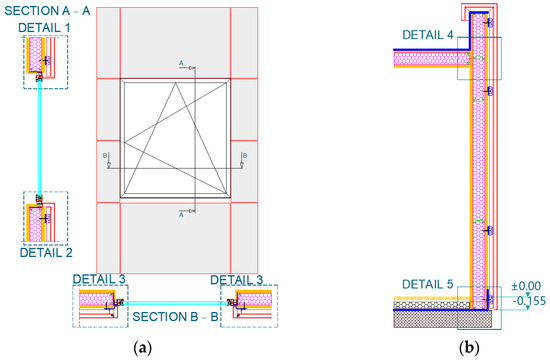
Figure 4.
Cross-sections marked on elements. (a) Face of the panel; (b) Cross-section of the panel.
Details 1, 2, and 3 (Figure 4a) show window-to-wall connections in different sections, Details 1 and 2 are vertical sections, while Detail 3 shows the horizontal section. Numerical calculation is carried out by standard EN ISO 10211 [22].
Detail 4 (Figure 4b) represents the wall-to-roof connection. As vertical and horizontal elements of wall and roof have to connect at the right angle and cannot be connected at an obtuse angle, consequently, the outside connection surface is much bigger than that of the inside surface. The difference in surface geometry disturbs heat flows, resulting in higher heat losses. In addition to the geometric thermal bridge, the impact of the steel frame, which consists of two different elements, should also be considered, as they are very close to each other.
Detail 5 (Figure 4b) represents wall to floor slab connection. Similar to Detail 4, Detail 5 has the same geometrical problems, but on top of the geometrical thermal bridge, additional transmission heat losses are caused by connection with the ground. Heat losses for components in direct contact with the ground are calculated according to the [22].
3.5. Buildings Elements Overall Heat Transfer Calculation
-value represents 1D heat transfer, which does not consider the impact of steel. Calculation of -value is shown in (1) [23]:
where and are internal and external surface heat transfer coefficients taken according to Table 1, and and are taken according to Table 2.

Table 1.
Surface heat transfer coefficient.

Table 2.
Model element properties.
To clearly present the impact of different setups of detail junctions for thermal bridge optimization, calculation of is done according to (2) [22].
where is the two-dimensional thermal coupling coefficient obtained from a 2D calculation of the component separating the two environments being considered. represents the thermal transmittance of the 1D component, , separating the two environments being considered. is the length over which the value applies. are the linear transmittances considered of the linear thermal bridge separating the two environments. Using the , -value can be determined. In the calculation of the , the influence of elements -value, -value, the connection of two different elements and the steel studs are considered.
Boundary conditions for internal and external environments are consistent with EN ISO 10211 [22] and EN ISO 6946 [23]. The temperature of the external environment is defined as −10 °C so that extreme winter conditions are taken into account, while the internal environment is considered to be heated to 20 °C. The calculations of surface heat transfer coefficients (), which are derived from the thermal resistance (-value) specified in the EN ISO 6946 [23] standard. Table 1 displays the resulting surface heat transfer coefficients. These values depend on the type of surface (interior or exterior) as well as heat flow direction. The external thermal resistance mainly depends on the wind direction and velocity, as well as the surface roughness [14,24].
The thermal conductivity values of the materials in the model, were selected according to [20] and are shown in Table 2. Layer characteristics for every calculation model can also be found in Table 2 with respective layer labels. Models used for calculation of -value do not contain hydro isolation, wind, and air tightness membranes as they have minimal impact on elements thermal transmittance.
2D models require much less time and are less demanding than 3D models, therefore, it was decided to run this numerical calculation on 2D models due to results of a recently unpublished study by the same authors that show result differences between 2D and 3D models are less than 10%. Numerical calculations were performed using the CRORAL v1.2 software [25].
in Table 2 is taken according to DIN 4108, Beiblatt 2 [26], which was shown to be an acceptable approach by Schild [27] when window properties are not known in the design stage. Schild [27] argued that the -value of windows can be approximated by a calculation on a model constructed from blocks with the same thickness as the actual window frame, with a thermal resistance (-value) equal to the -value of the glass in the real window.
Figure 5 shows the methodology flow chart.
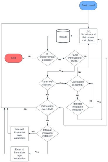
Figure 5.
Methodology flow chart.
3.5.1. Elements with Rigid PUR Foam as Cavity Insulation
Table 3 shows all the setups that are calculated for Details 1–5. In total, 45 combinations for PUR foam as cavity insulation is made. Table 3 shows a binary display where 0 means absence, while 1 means the presence of metal frame, installation layer, or additional external insulating layer. The layer for installations is made of 5 cm thick mineral wool put on top of the existing gypsum fiber boards and an air tightness layer and coated with another gypsum fiber board on the internal side of the basic panel.

Table 3.
Calculation setups for Details 1–5 with rigid PUR foam as cavity insulation.
The additional external layer is made of 8 cm thick mineral wool put on top of the existing gypsum-fiber fire board layer, which is made as a ventilated façade. External insulation is found only in combination with internal insulation on the basic panel. Cases without steel studs do not contain spacers.
Numerical calculation for each model is carried out with real buildings’ envelope layers and material properties, as shown in Table 2.
Figure 6, Figure 7, Figure 8, Figure 9 and Figure 10 show basic KLIK panels for all 5 details with steel frame without spacers and setups with additional thermal insulation with their corresponding temperature distribution:
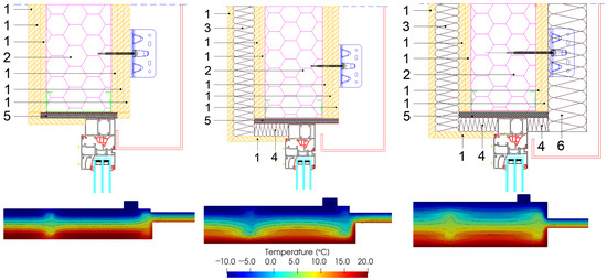
Figure 6.
Setup of Detail 1 for KLIK panel with steel frame without spacers.
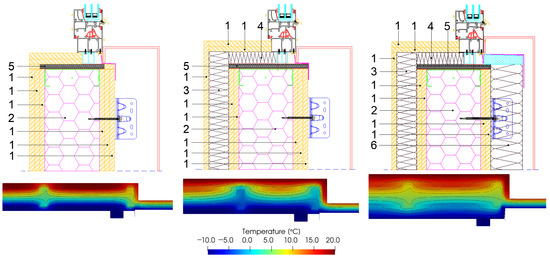
Figure 7.
Setup of Detail 2 for KLIK panel with steel frame without spacers.
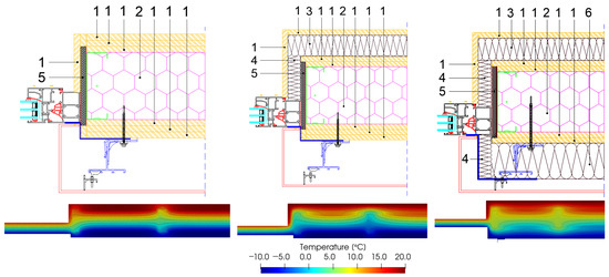
Figure 8.
Setup of Detail 3 for KLIK panel with steel frame without spacers.
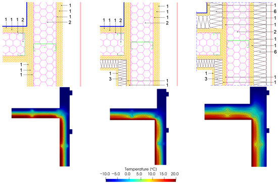
Figure 9.
Setup of Detail 4 for KLIK panel with steel frame without spacers.
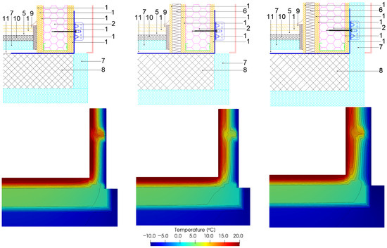
Figure 10.
Setup of Detail 5 for KLIK panel with steel frame without spacers.
- Figure 6 shows 3 setups of KLIK panel with steel frame without spacers (Detail 1);
- Figure 7 shows 3 setups of KLIK panel with steel frame without spacers (Detail 2);
- Figure 8 shows 3 setups of KLIK panel with steel frame without spacers (Detail 3);
- Figure 9 shows 3 setups of KLIK panel with steel frame without spacers (Detail 4);
- Figure 10 shows 3 setups of KLIK panel with steel frame without spacers (Detail 5).
Figure 11, Figure 12, Figure 13, Figure 14 and Figure 15 show the basic panel for all 5 details with steel frame and spacers and setups of additional thermal insulation with their belonging temperature distribution for KLIK panel:
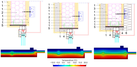
Figure 11.
Setups of Detail 1 for KLIK panel with steel frame with spacers.
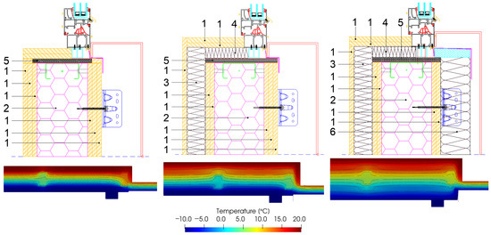
Figure 12.
Setup of Detail 2 for KLIK panel with steel frame with spacers.
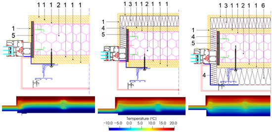
Figure 13.
Setup of Detail 3 for KLIK panel with steel frame with spacers.
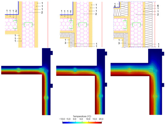
Figure 14.
Setup of Detail 4 for KLIK panel with steel frame with spacers.
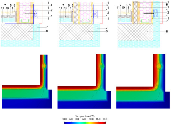
Figure 15.
Setup of Detail 5 for KLIK panel with steel frame with spacers.
- Figure 11 shows 3 setups of KLIK panel with steel frame with spacers (Detail 1);
- Figure 12 shows 3 setups of KLIK panel with steel frame with spacers (Detail 2);
- Figure 13 shows 3 setups of KLIK panel with steel frame with spacers (Detail 3);
- Figure 14 shows 3 setups of KLIK panel with steel frame with spacers (Detail 4);
- Figure 15 shows 3 setups of KLIK panel with steel frame with spacers (Detail 5).
Due to space constraints of this paper, only representative details with belonging temperature distribution in the cross-section are shown. The rest of the results are shown in an analogous manner in Section 4.
3.5.2. Elements with Mineral Wool as Cavity Insulation
Table 4 shows all the setups that are calculated for Details 1–5. In total, 45 combinations for LSF with MW as cavity insulation is made. Table 4 shows a binary display where 0—means absence while 1—means presence. The layer for installations is made of 5 cm thick mineral wool put on top of the existing layer of gypsum-fiber board and coated with another gypsum fiber board on the internal side of the basic panel.

Table 4.
Calculation setups for Details 1–5 with mineral wool as cavity insulation.
The additional external layer is made of 8 cm thick mineral wool put on top of the existing layer of gypsum fiber fireboard, which is made as a ventilated façade. External insulation is found only in combination with internal insulation on the basic panel. Cases without steel studs do not contain spacers.
Figure 16, Figure 17, Figure 18, Figure 19 and Figure 20 show the basic panel for all 5 details with steel frame and spacers and setups of additional thermal insulation with their belonging temperature distribution for LSF panel with mineral wool as cavity insulation:
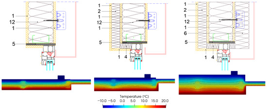
Figure 16.
Setup of Detail 1 LSF panel with MW with steel frame and spacers.
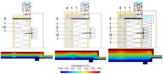
Figure 17.
Setup of Detail 2 LSF panel with MW with steel frame and spacers.
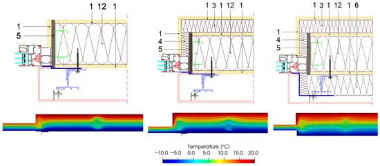
Figure 18.
Setup of Detail 3 LSF panel with MW with steel frame and spacers.
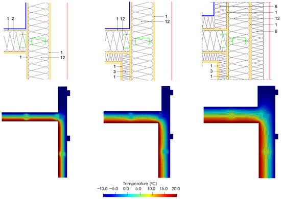
Figure 19.
Setup of Detail 4 LSF panel with MW with steel frame and spacers.
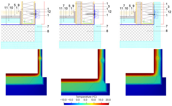
Figure 20.
Setup of Detail 1 LSF panel with MW with steel frame and spacers.
- Figure 16 shows 3 setups of LSF panel with MW and steel frame with spacers (Detail 1);
- Figure 17 shows 3 setups of LSF panel with MW and steel frame with spacers (Detail 2);
- Figure 18 shows 3 setups of LSF panel with MW and steel frame with spacers (Detail 3);
- Figure 19 shows 3 setups of LSF panel with MW and steel frame with spacers (Detail 4);
- Figure 20 shows 3 setups of LSF panel with MW and steel frame with spacers (Detail 5).
Due to space constraints of this paper, only representative details with belonging temperature distribution in the cross-section are shown. The rest of the results are shown in an analogous manner.
4. Results and Discussion
The comparison of and -values between KLIK panel and LSF panel with MW as cavity insulation is shown in Figure 21, Figure 22, Figure 23, Figure 24 and Figure 25. Three different setups of the same detail are made: basic panel (B), basic panel with additional installation layer (IL + B), and basic panel with a combination of installation layer + external layer of insulation (IL + B + EL). On top of additional layers, the effect of different steel studs is compared. With additional insulation layers on the basic panel, the -value changes.
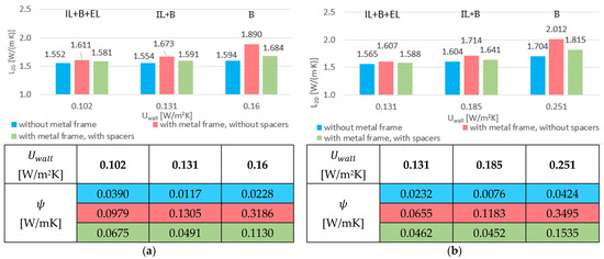
Figure 21.
Results of Detail 1 for total heat transmission through KLIK panel and LSF panel with MW as cavity insulation and belonging -values. (a) Setups of Detail 1 for KLIK panel, (b) setups of Detail 1 for LSF panel with MW as cavity insulation.
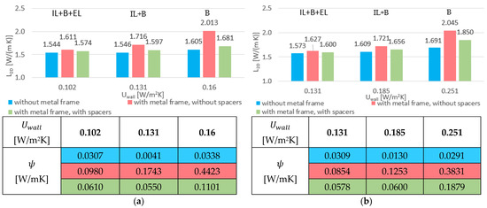
Figure 22.
Results of Detail 2 for total heat transmission through KLIK panel and LSF panel with MW as cavity insulation and belonging -values. (a) Setups of Detail 2 for KLIK panel, (b) setups of Detail 2 for LSF panel with MW as cavity insulation.
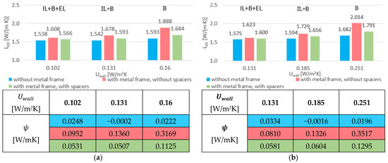
Figure 23.
Results of Detail 3 for total heat transmission through KLIK panel and LSF panel with MW as cavity insulation and belonging -values. (a) Setups of Detail 3 for KLIK panel, (b) setups of Detail 3 for LSF panel with MW as cavity insulation.
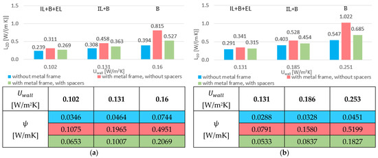
Figure 24.
Results of Detail 4 for total heat transmission through KLIK panel and LSF panel with MW as cavity insulation and belonging -values. (a) Setups of Detail 4 for KLIK panel, (b) setups of Detail 4 for LSF panel with MW as cavity insulation.
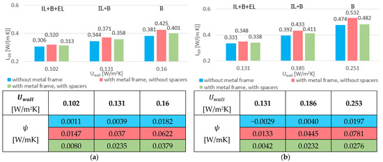
Figure 25.
Results of Detail 5 for total heat transmission through KLIK panel and LSF panel with MW as cavity insulation and belonging -values. (a) Setups of Detail 5 for KLIK panel, (b) setups of Detail 5 for LSF panel with MW as cavity insulation.
In Figure 21, Figure 22, Figure 23, Figure 24 and Figure 25, the x-axis shows the 1D heat transfer for the steady state heat flow between steel studs. includes 1D heat transfer and the impact of thermal bridges in cases with and without steel studs for each detail. Figure 21, Figure 22, Figure 23, Figure 24 and Figure 25 also show -values with respect to -values of Details 1–5 for KLIK panel and LSF panel with MW as cavity insulation. Values in tables represent the same cases as bar charts.
Windows in Details 1, 2 and 3 have much higher -values than walls, therefore, they have a much greater impact on . A change in the -values of walls has a smaller percentage impact on since the -value of windows remains the same.
4.1. Impact of Steel Frame
In cases without steel studs (blue columns), represents the sum of total heat transmission of all 1D heat transfers (wall, roof, etc.) and thermal bridges at the connections between two elements. In cases without stud framing, the is the lowest because of the exclusion of steel frame. In this case, additional layers have the least impact on compared to the other cases with steel frames.
In cases with steel studs but without spacers (red columns), represents the sum of the total heat transmission of all 1D heat transfers (wall, roof, etc.), thermal bridges at the joints of two elements, and thermal bridges caused by steel studs. In this case, thermal bridges have a great impact on , because a continuous metal frame allows free heat transfer through the element, as a steel frame penetrates the thermal insulation. Heat can enter and exit metal frames unimpeded because it has surface-to-surface contact with gypsum fiber boards, which increases the heat flux density. This leads to the highest .
Steel frames are mandatory and cannot be excluded from wall elements. A solution has been found in PVC spacers that can help minimize the effects of thermal bridges.
In cases with steel studs with spacers (green columns), represents the sum of total heat transmission of all 1D heat transfers (wall, roof, etc.), thermal bridges at the joints of two elements, and thermal bridges caused by the steel studs. Spacers allow a continuous distance between the steel frame and the gypsum fiber board so that the extra space can be filled with the same material as the cavity inside of panel ensuring there is no direct contact between steel studs and the gypsum fiber board. As the only difference between the red and green cases is in spacers, the difference in shows the impact of steel separation from gypsum fiber boards. has lower values than cases with metal frames but without spacers. Spacers have the greatest effect on basic panels because they have minimal thermal insulation, so the steel studs are directly breaching the entire thermal insulation. The impact of spacers varies from detail to detail, but the effect is significant as the difference between basic panels with and without spacers for KLIK panels is 36% in favor of spacers.
Detail 4 shows the spot where the wall and roof meet. Their connection requires a lot of steel to safely transfer loads, so the largest decrease in (both absolute and percentage) is found in Detail 4. The explanation lies in the large amounts of steel that are very close to each other and the proximity of the geometric thermal bridge, which results in high heat flux. The use of spacers or additional thermal insulation reduces the influence of the thermal bridge.
4.2. Impact of Cavity Insulation Material
According to [20], PUR foam has almost 64% lower than MW. The effect of the lower results in a lower -value and thus a lower . KLIK panel in its basic form has a 57% lower -value than LSF panel with MW. With additional layers of MW, the difference in -value becomes smaller but is still in favor of the KLIK panel. In the thickest form, with internal and external insulation, KLIK panel has a 28% lower -value. When comparing all cases, thanks to lower -value, KLIK panel has a 7 to 20% lower , depending on the case.
When comparing for each detail, Details 1, 2, and 3 have similar results because they represent the same element connection (window to wall). Details 4 and 5 have the lowest total heat transfer through the building element, as Detail 4 has only a geometric thermal bridge and Detail 5 has a slab that is in contact with the ground.
4.3. Impact of Additional Layers
The second parameter shown in Figure 21, Figure 22, Figure 23, Figure 24 and Figure 25 is the -value. The installation of additional layers on basic panels decreases the -value, which leads to decrease in .
The greatest effect in decreasing the occurs when external insulation is added to the panel with internal insulation, regardless of cavity insulation material or steel studs.
Comparing the effects of additional thermal insulation layers on the basic KLIK panel, the -value decreases by 18% with internal insulation and by another 22% with external insulation, corresponding to a 46% lower -value compared to the basic panel.
If the same comparison is made for the basic LSF panel with MW as cavity insulation, the -value is decreased by 26% with the installation of internal insulation, and if external insulation is applied, -value is decreased by an additional 29%, which corresponds to a 48% lower -value than the basic panel.
Comparing the effect of additional layers, LSF with MW has a higher -value than the KLIK panel with additional thermal insulation.
Although steel studs have significantly higher thermal conductivity than thermal insulation, they cause material thermal bridges. If thermal insulation is properly installed on the internal and external side, then the effects of the thermal bridges can be minimized.
Adding an installation layer on basic panels, lowers not only the difference between the -values of the two cases but also the effects of thermal bridges.
Thanks to the additional thermal insulation on both internal and external sides, direct contact of steel studs with the outer gypsum fiber board is prevented, which further reduces the effects of thermal bridges and enables higher surface temperatures.
Thermal bridges have a strong impact on , but are not as pronounced on basic panels since the entire panel has a relatively weak thermal performance. As the thickness of the thermal insulation increases, the thermal performance of the entire panel improves, but the impact of thermal bridges is more pronounced.
5. Conclusions
In this study, the thermal properties of two types of steel load-bearing structures are compared in a total of 90 cases. The KLIK panel, whose cavity insulation is filled with PUR foam (45 cases), and the LSF panel, whose cavity is filled with mineral wool (45 cases). When compared with the LSF panel, the KLIK panel has a 57% lower heat transfer coefficient in its basic version. Calculations have also been made for the cases when internal insulation is applied separately for both types of structures and for the case when internal and external insulation are applied simultaneously. In both cases, the KLIK panel has a lower -value, which is in line with expectations and is 41% lower when only internal insulation is applied and 28% for the case when both internal and external insulation is applied, thanks to lower thermal conductivity of PUR foam. When comparing thermal properties, the influence of steel studs and additional thermal insulation layers on was also investigated for all five details.
The general problem with LSF panels is an increased heat flow through the element due to the steel studs, especially at their junctions, where horizontal, vertical, and diagonal studs meet.
The cases without steel studs represent the total heat flow through elements with the effect of thermal bridges but without the influence of steel studs. In this way, the influence of steel studs can be examined separately by comparing with other cases with steel studs and cases with steel studs with spacers.
The calculation shows the possibility of reducing the effect of thermal bridges by installing additional thermal insulation to the internal and external surfaces of the panels, successfully reducing the effect of the steel studs on the overall heat transfer in all five details, as well as the effect of the thermal bridge effect due to changes in geometry and material. A great improvement in lowering the was also achieved by placing spacers between the steel studs and covering boards. The results are different in all cases, but the biggest difference in lowering the is in the basic panels, where the influence of the thermal bridges due to the steel studs is the biggest. By placing PVC spacers between the steel frame, can be reduced by 35% (Detail 4 PUR).
Results for absolute -values are also obtained for each detail; however, their significance is relative due to the alteration in geometry among cases. Consequently, for a more meaningful comparison, the utilization of values are recommended.
When analyzing the surface temperature of the elements, scenarios excluding a metal frame result in the highest surface temperatures. This outcome is attributed to the absence of a steel frame that disrupts the thermal insulation of the basic panel. However, it is important to note that the inclusion of a steel frame is essential for the load-bearing role of elements, rendering these cases predominantly theoretical and serving as informative benchmarks. In scenarios featuring both a metal frame and PVC spacers, surface temperatures tend to be higher compared to scenarios with a metal frame alone. The presence of a steel frame significantly influences temperature distribution. The elevated surface temperature in such cases contributes to a reduced likelihood of mold and fungus growth.
For future research, the authors recommend a more detailed examination of point thermal bridges, specifically those attributed to PVC spacers is imperative. The effects of those localized thermal bridges on the overall energy performance and heat transfer need to be thoroughly understood.
The ingress of moisture into LSF panels can have far-reaching consequences on their thermal properties and structural integrity. A comprehensive study should delve into mechanisms of moisture infiltration, its migration pathways, and its impact on both thermal performance and the overall longevity of the panels.
This study has focused on the five primary connections between elements. However, a thorough exploration of connections, such as penetrations, junctions, and intersections of elements, will provide a more holistic understanding of heat transfer pathways and potential areas of improvement.
Author Contributions
Conceptualization, B.M.; Methodology, B.M.; Software, D.T. and M.G.; Validation, B.M. and M.G.; Investigation, D.T.; Resources, M.G. and M.J.R.; Data curation, D.T.; Writing—original draft, D.T.; Writing—review & editing, B.M., M.G., M.J.R. and I.B.P.; Visualization, D.T.; Supervision, B.M. and I.B.P.; Project administration, M.J.R.; Funding acquisition, I.B.P. All authors have read and agreed to the published version of the manuscript.
Funding
This research was funded by the European Union through the European Regional Development Fund’s Competitiveness and Cohesion Operational Program, grant number KK.01.1.1.07.0060, project “Composite lightweight panel with integrated load-bearing structure (KLIK-PANEL)”.
Data Availability Statement
Interested readers can directly contact the authors.
Acknowledgments
The authors extend their gratitude to the companies Tehnoplast profili d.o.o. and Palijan d.o.o. for their assistance with inputs in the construction technology.
Conflicts of Interest
The authors declare no conflict of interest.
References
- Milovanović, B.; Bagarić, M.; Gaši, M.; Strmo, N.V. Case Study in Modular Lightweight Steel Frame Construction: Thermal Bridges and Energy Performance Assessment. Appl. Sci. 2022, 12, 20. [Google Scholar]
- Rukavina, M.J.; Skejić, D.; Kralj, A.; Ščapec, T.; Milovanović, B. Development of Lightweight Steel Framed Construction Systems for Nearly-Zero Energy Buildings. Buildings 2022, 12, 7. [Google Scholar]
- Jaysawal, R.; Chakraborty, S.; Elangovan, D.; Padmanaban, S. Concept of net zero energy buildings (NZEB)—A literature review. Clean. Eng. Technol. 2022, 11, 100582. [Google Scholar] [CrossRef]
- Brito, R.; Villa, D.; Zalamea, E. Comparative analysis of thermal comfort of a single-family house in LSF and brick masonry. Ingenius 2022, 28, 106–130. [Google Scholar]
- Atalić, J.; Demšić, M.; Baniček, M.; Uroš, M.; Dasović, I.; Prevolnik, S.; Kadić, A.; Novak, M.; Nastev, M. The December 2020 Magnitude (Mw) 6.4 Petrinja Earthquake, Croatia: Seismological Aspects, Emergency Response and İmpacts; Springer: Berlin/Heidelberg, Germany, 2022. [Google Scholar]
- Thapa, B.M.; Pasang, S. Feasibility of prefabricated building structures in Bhutan. J. Appl. Eng. Technol. Manag. 2023, 3, 10–22. [Google Scholar] [CrossRef]
- Li, S.; Li, S.; Hu, J.; Shi, Y.; Li, H.; Chen, A.; Xie, W. Intelligent Modeling of Edge Components of Prefabricated Shear Wall Structures Based on BIM. Buildings 2023, 13, 1252. [Google Scholar] [CrossRef]
- Fang, Y.; Xu, Y.; Gu, R. Experiment and Analysis of Mechanical Properties of Lightweight Concrete Prefabricated Building Structure Beams. Int. J. Concr. Struct. Mater. 2022, 16, 1–11. [Google Scholar] [CrossRef]
- Stepinac, M.; Lourenço, P.B.; Atalić, J.; Kišiček, T.; Uroš, M.; Baniček, M.; Novak, M.Š. Damage classification of residential buildings in historical downtown after the ML5.5 earthquake in Zagreb, Croatia in 2020. Int. J. Disaster Risk Reduct. 2021, 56, 102140. [Google Scholar] [CrossRef]
- TSN News Cold-Formed Steel Framing. Light Steel Frame. Available online: https://steelnetwork.com/company/light-steel-framing-news/ (accessed on 23 December 2022).
- Moga, L.; Petran, I.; Santos, P.; Ungureanu, V. Thermo-Energy Performance of Lightweight Steel Framed Constructions: A Case Study. Buildings 2022, 12, 3. [Google Scholar] [CrossRef]
- Guillén-Lambea, S.; Rodríguez-Soria, B.; Marín, J.M. Air infiltrations and energy demand for residential low energy buildings in warm climates. Renew. Sustain. Energy Rev. 2019, 116, 109469. [Google Scholar] [CrossRef]
- Roque, E.; Vicente, R.; Almeida, R. Indoor Thermal Environment Challenges of Light Steel Framing in the Southern European Context. Energies 2021, 14, 7025. [Google Scholar] [CrossRef]
- Santos, P.; Lemes, G.; Mateus, D. Thermal transmittance of internal partition and external facade LSF walls: A parametric study. Energies 2019, 12, 2671. [Google Scholar] [CrossRef]
- Santos, P.; Lemes, G.; Mateus, D. Analytical methods to estimate the thermal transmittance of LSF walls: Calculation procedures review and accuracy comparison. Energies 2020, 13, 4. [Google Scholar] [CrossRef]
- Manzan, M.; De Zorzi, E.Z.; Lorenzi, W. Numerical simulation and sensitivity analysis of a steel framed internal insulation system. Energy Build. 2018, 158, 1703–1710. [Google Scholar] [CrossRef]
- Santos, P.; Lopes, P.; Abrantes, D. Thermal Performance of Lightweight Steel Framed Facade Walls Using Thermal Break Strips and ETICS: A Parametric Study. Energies 2023, 16, 1699. [Google Scholar] [CrossRef]
- Liang, H.; Roy, K.; Fang, Z.; Lim, J.B.P. A Critical Review on Optimization of Cold-Formed Steel Members for Better Structural and Thermal Performances. Buildings 2022, 12, 34. [Google Scholar] [CrossRef]
- Ščapec, T.; Rukavina, M.J. Review of thermal performance of LSF walls used for nZEB: Influence of components. In Proceedings of the 7th Symposium on Doctoral Studies in Civil Engineering, Zagreb, Croatia, 6–7 September 2021; pp. 107–121. [Google Scholar]
- Ministarstvo Prostornog Uređenja Graditeljstva i Državne İmovine. Tehnički Propis o Racionalnoj Uporabi Energije i Toplinskoj Zaštiti u Zgradama; Narodne Novine: Zagreb, Croatia, 2020.
- Combustibility Groups and Classes: An İntroduction to Often Used Terminology in Fire Protection. Available online: https://www.promat.com/en/construction/news/145210/combustibility-groups-and-classes/ (accessed on 12 May 2023).
- EN ISO 10211; Thermal Bridges in Building Construction—Heat Flows and Surface Temperatures—Detailed Calculations. The European Committee for Standardiuation: Brusels, Belgium, 2017.
- EN ISO 6946; Building Components and Building Elements—Thermal Resistance and Thermal Transmittance—Calculation Methods. The European Committee for Standardization: Brusels, Belgium, 2017.
- Evangelisti, L.; Guattari, C.; Gori, P.; Bianchi, F. Heat transfer study of external convective and radiative coefficients for building applications. Energy Build. 2017, 151, 429–438. [Google Scholar] [CrossRef]
- Gaši, M. CRORAL—Computer Program for Thermal Bridge Analysis and Vapour Analysis; Faculty of Civil Engineering, University of Zagreb: Zagreb, Croatia, 2023. [Google Scholar]
- DIN 4108 Beiblatt 2:2019-06; Wärmeschutz und Energie-Einsparung in Gebäuden; Beiblatt 2: Wärmebrücken. Deutsches Institut für Normung: Berlin, Germany, 2019.
- Schild, K. Wärmebrücken-Berechnung und Mindestwärmeschutz; Springer Fachmedien Wiesbaden: Wiesbaden, Germany, 2018. [Google Scholar]
Disclaimer/Publisher’s Note: The statements, opinions and data contained in all publications are solely those of the individual author(s) and contributor(s) and not of MDPI and/or the editor(s). MDPI and/or the editor(s) disclaim responsibility for any injury to people or property resulting from any ideas, methods, instructions or products referred to in the content. |
© 2023 by the authors. Licensee MDPI, Basel, Switzerland. This article is an open access article distributed under the terms and conditions of the Creative Commons Attribution (CC BY) license (https://creativecommons.org/licenses/by/4.0/).