Article

Identification and Analysis of Noise Sources of Permanent Magnet Synchronous Traction Motor with Interior Permanent Magnet

1
Łukasiewicz Research Network-Upper Silesian Institute of Technology, 44-100 Gliwice, Poland
2
Power Electronics, Electrical Drives and Robotics Department, Faculty of Electrical Engineering, Silesian University of Technology, 44-100 Gliwice, Poland
*
Author to whom correspondence should be addressed.
Energies 2023, 16(16), 6018; https://doi.org/10.3390/en16166018
Submission received: 17 July 2023 / Revised: 10 August 2023 / Accepted: 11 August 2023 / Published: 17 August 2023
(This article belongs to the Special Issue New Solutions in Electric Machines and Motor Drives)

Abstract

:
The rapid development of electromobility is placing ever higher demands on new electric motor designs. This results in a gradual reduction in weight with a simultaneous increase in maximum torque. As a result, unfavorable phenomena, such as vibration and noise, can become apparent in the drivetrain. Modeling and evaluation of the acoustic noise sources of a traction motor are particularly important when it is used, for example, as the traction drive of an electric bus, where too high noise levels can have a negative impact on passengers. This article describes methods for analyzing and evaluating the root causes of noise that occurs in permanent magnet traction motors with a rotor in which the magnets have been placed inside the rotor (PMSM IPM). This paper presents an analysis of acoustic noise and forces acting in the air gap of a 240 kW motor with 60 stator slots and 2p = 10 (s60p20) as the number of pole pairs designed for bus and truck drives. To determine the dominant noise sources and evaluate their value, the forces acting in the air gap and their effect on the deflection of the outer surface of the stator yoke were calculated. The natural frequencies of the machine, their frequencies for the entire rotor speed range, and the frequency of vibration of the motor stator were calculated. Based on these data, the sound power level (A-SWL) was calculated at varying motor speeds. MANATEE software (EOMYS, 9, avenue de la Créativité, 59650 Villeneuve d’Ascq—FRANCE) from EOMYS was used to perform vibroacoustic calculations. The analysis results were also subjected to verification on a laboratory bench.

1. Introduction

Both in European [1] and other highly developed countries, there has recently been a rapid increase in the number of electric vehicles of all kinds and related technologies. This is due, among other things, to the introduction of regulations aimed at reducing the CO2 emissions [1] and noise [2] generated by road transport vehicles. According to a European Union publication [2], about 40% of the population in EU countries are exposed to traffic noise levels exceeding 55 dB(A), and 20% are exposed to levels exceeding 65 dB(A) during the day. In contrast, more than 30% are exposed to levels exceeding 55 dB(A) at night. In addition, in recent years, the problems occurring in the fuel market caused not only by environmental aspects but also by political ones have become increasingly apparent. This has a very strong impact on the global economy, for which road transportation is an extremely important component. Electric cars and vehicles therefore fit perfectly into these new trends and legal requirements, as one of their main advantages is their very low noise emissions. At one stage, they even proved to be too quiet. Pedestrians are accustomed to the sound of approaching cars generated by the ubiquitous internal combustion engines. At the low speeds allowed in urban areas, electric-powered vehicles have low enough external noise levels to threaten pedestrian safety. This has even led to acts [3] in legislation in the European Union to ensure that all motor vehicles provide a certain minimum level of external noise. As of 1 July 2021, every new electric and hybrid car operating in zero-emission mode must generate sound. According to the adopted regulations, the sound emitted must be continuous, with a minimum volume of 56 dB at 20 km/h and a maximum volume of 75 dB at higher speeds [3]. Accordingly, new electric cars are equipped with sound generators that increase the external noise level at low speeds. The system that accomplishes this is called the Acoustic Vehicle Alerting System—AVAS. This raises the question of whether the issue that is the subject of this publication, i.e., noise analysis of electric drives, makes sense in such a case. It turns out, however, that in these drives there may also be situations in which the generated noise will disturb the vehicle user and bystanders, particularly in the area of higher propulsion motor speeds, where the source of noise becomes not only the motor itself but also other mechanical components of the vehicle’s transmission. This is related, for example, to the use of mechanical transmissions (with one or two gear ratios) in electrically powered vehicles [4]. In addition, they can also cause other unfavorable phenomena, i.e., vibration or oscillation, which can affect the comfort of users through design. However, this article is not concerned with optimizing the vehicle’s mechanical solutions, so in what follows the analysis will focus only on the electric motor, which is a key component of an electric vehicle. For most traction motors, the sound radiated from the motor housing is important in terms of acoustic noise. What ultimately matters is the sound power or sound pressure. Of lesser importance are the vibrations and oscillations generated, which are essentially nonexistent in a properly operating motor. Electric drives have a predisposition to produce high-frequency noise that is particularly unpleasant for humans [5]. This is because this type of sound is generally considered annoying, even if its level is low. In addition, this frequency range can be heard even in hybrid vehicles equipped with a traditionally noisy internal combustion engine [6]. However, this is due to the nature of internal combustion engines, which are characterized by noise that is broadband in nature but localized in the lower frequency range [4]. Badly designed drives can also adversely affect animals, with boat drives as an example. In this case, too much noise and vibration from the drive could disturb the natural environment of fish, birds, and other animals inhabiting lakes and reservoirs, contributing to a decline in their populations.

1.1. Noise Sources

Sources of noise and vibration in electrical machinery are usually classified as follows [7,8]:
  • Mechanical;
  • Aerodynamic;
  • Magnetic.
Mechanical noise and vibration, which can come from bearings, gears, and brush commutators, are present in traction drives, but their frequencies are usually lower than the frequency of electromagnetically induced noise, and their level is not high [7]. The vibration and noise produced by bearings depend on the following [7]:
  • The accuracy of their parts;
  • The frequency of mechanical resonance in the outer ring;
  • The speed;
  • Lubrication conditions;
  • Tolerances;
  • The alignment;
  • The load;
  • The lubricant temperature;
  • The stability and spin of the oil film in the bearing;
  • The manufacturing process;
  • The quality and assembly.
However, by making the motor with due care, it can be assumed that the motor rotor is properly balanced, the eccentricity of the rotor is negligibly small, and the ovality of the shaft journals and bearing surfaces is within tolerance. In such a situation, mechanical noise can be treated as negligible under normal operating conditions and will therefore not be analyzed further.
Aerodynamic noise is caused by periodic changes in air pressure from installed fans or air turbulence in the air gap caused by stator stalling. In machines operating at high speeds, aerodynamic forces can also cause vibration of the stator and machine housing and, in extreme cases, can be a source of high-pitched noise. Electric traction drives are usually liquid-cooled; however, this is due to the environment in which such drives are used. Usually, the traction motor housing is also sealed. For this type of motor, ventilation and aerodynamic noise are negligibly small and, like mechanical noise, will not be considered further.
Noise sources classified as magnetic are the most common causes of traction motor noise [9]. Some of the most common motors used in electric or hybrid drives are permanent magnet synchronous motors [7,10] and their subgroups SM-PMSM (with magnets mounted on the rotor surface) [11,12,13,14,15,16] and IPMSM (with magnets located inside the rotor) [16,17,18,19,20,21,22,23]. These motors are used for their excellent traction characteristics, high power density, and high efficiency. However, especially in this type of motor, the influence of radial forces, the source of which is permanent magnets, becomes apparent. These forces act on both the stator and the rotor and can cause the deformation of magnetic circuits [14]. If the frequency of variation in the radial force and other forces deforming the stator is close to or equal to one of the natural frequencies of the stator–rotor system, resonance occurs. This leads to the deformation of the stator yoke and motor housing and the generation of vibrations and acoustic sound radiated through the motor housing and frame [11,24]. When the power level of these sounds exceeds a set threshold, they become noise. The constant striving to achieve more power and torque in motors with unchanged mass and to increase electromechanical parameters [25,26,27,28] involves the increasing use of active parts of the motor. As a result, the forces acting on the individual components of the motor are also increasing while the structure itself is becoming more susceptible to deformation, thus increasing the level of generated noise [24]. An assessment of the nature and level of electromagnetic vibration is necessary, especially in the design of traction drive motors, which must operate over a wide speed range and under very high magnetic loads. In this case, appropriate vibroacoustic assumptions will be as important as electromagnetic or thermal ones. The analysis of the harmonic densities of the radial forces with which the motor rotor interacts with the stator being used is one of the most important steps in the acoustic noise source analysis issue. This is because it makes it possible to clarify the correlation between acoustic noise and the higher harmonics of the radial force density. In IPMSM motors, the content of radial force density harmonics in the air gap strongly depends on the design of the rotor’s magnetic circuit, the arrangement of permanent magnets, and the arrangement and length of the rotor’s magnetic bridges [29,30].

1.2. Vibration and Noise Reduction Methods

Many methods are used to reduce the vibration and noise of traction motors. Among them, we can include the following:
  • Increasing the stator and housing stiffness, but this approach is mostly associated with increasing the weight of the motor. Therefore, it is contrary to current trends of minimizing the weight of drives used in vehicles.
  • Reducing the value of the electromagnetic excitation force [27]. In this method, especially in motors with magnets, the value of the force that is responsible for the motor’s torque is also reduced. This affects the deterioration of motor performance.
  • The appropriate selection of the number of slots and the number of poles of the motor [14], so as to minimize the effect of Maxwell stresses on the stator structure over the entire range from the speed of the motor. The method allows us to reduce noise during machine design.
  • Reducing radial force pulsations by means of the harmonics of the supply current [31,32,33,34] or by mitigating torque pulsations [35,36].
The latter issue is most often analyzed in the literature related to methods of identifying noise sources in electric motors and methods of eliminating them. The reduction in the noise level of the machine obtained by reducing the harmonics of the current was confirmed in the work [37]. The paper analyzed a synchronous motor with a wound rotor that was fed from a modified inverter. The modification consisted of adding an additional control loop and filtering the sixth harmonic of the motor’s supply current, which reduced the higher mechanical harmonics that are a source of noise and vibration. One of the methods of reducing torque pulsation is to reduce the value of the so-called cogging torque [35,36]. This can be realized, among other things, by introducing a gradual bevel of the magnets into the rotor or making a bevel in the stator slots. This results in a significant reduction in acoustic noise, which was confirmed in the publications [35,36]. Another publication [38] analyzed the effect of supply current on torque and radial forces. It was found that both the d-axis current component and the q-axis current component affect radial force. These conclusions are relevant, especially for the IPMSM motor, which exhibits a large reluctance torque [39,40,41,42,43,44]. This makes the motor torque dependent on both the q-axis current and the d-axis current. The reluctance torque itself can therefore have a significant effect on the noise of the machine, as demonstrated in the work [45]. Among other things, this paper presents an interesting method of motor control that allows torque pulsations and average radial force density pulsations to be independently affected by the reluctance torque. This has the advantage that both force pulsations can be reduced. However, the greatest level of noise reduction requires carrying out full numerical optimization of the motor already at the machine design stage [46,47].

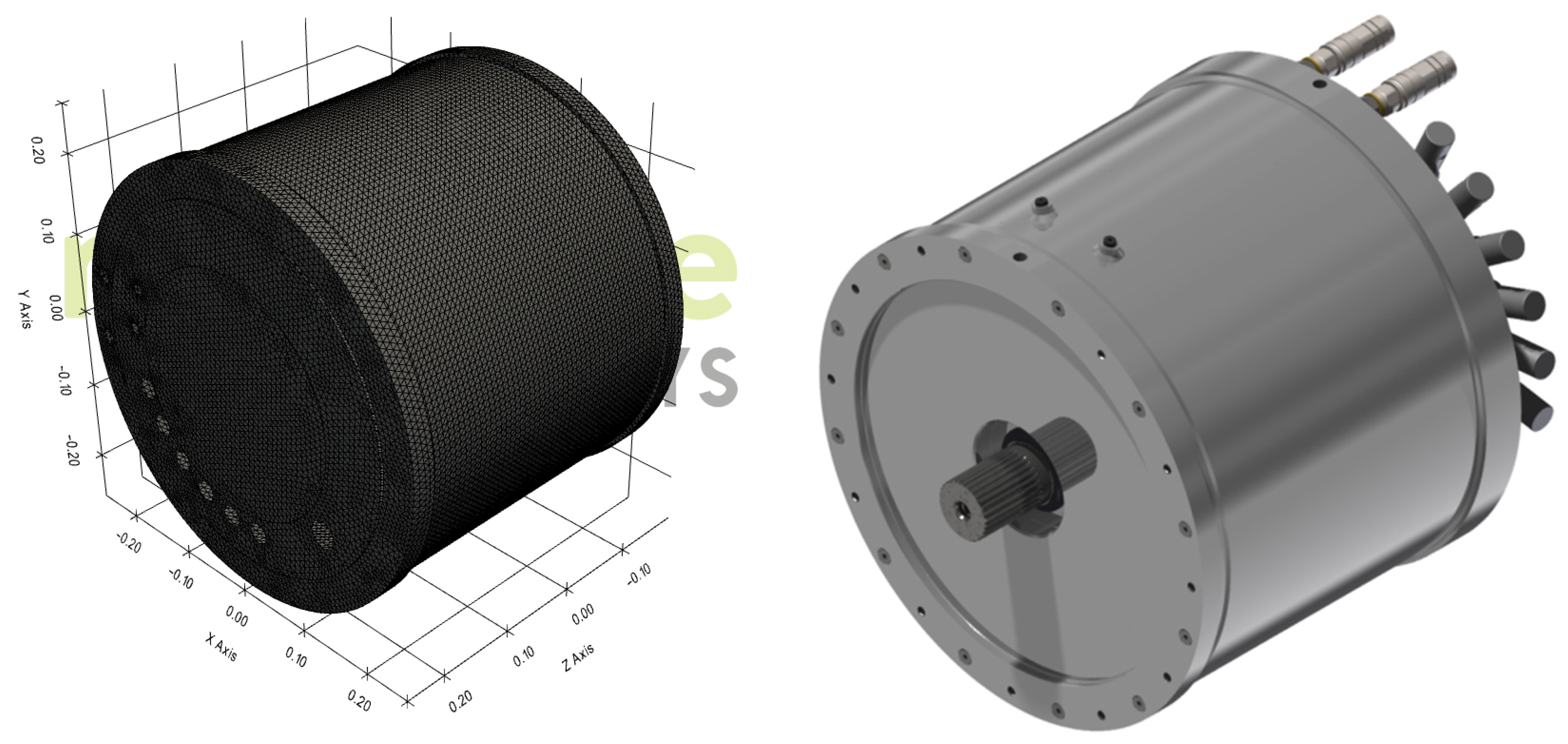
2. Traction Motor Design

For the purpose of the analyses, a traction motor to drive buses and trucks with a maximum power of 280 kW and a maximum torque of 2400 Nm was designed. The rated speed of the motor is 1100 rpm, and the maximum speed of the motor is 3000 rpm. The topology of the motor is shown in Figure 1. A motor model for vibroacoustic calculations was prepared in Pyleecan software (Version 1.5.0) [48]. The motor uses a stator slot skew of one slot pitch (6 mechanical degrees) to eliminate cogging torque and reduce motor torque ripple. The use of a stator skew makes the motor more difficult to manufacture; however, it allows for the complete elimination of cogging torque, which is especially important for such high-power motors and traction applications. In the calculation model, the skew of the rotor magnets corresponding to the skew of the stator by one slot pitch was used as a substitute. The SMwsK280M20 motor was designed as a permanent magnet synchronous motor with interior magnets (IPMSM), which is a 60-slot (Qs = 60) and 20-pole (p = 10) machine (Figure 1). This number of poles made it possible to obtain a high electromagnetic torque from the permanent magnets, while the reluctance asymmetric rotor design also makes the motor characterized by reluctance torque. The total motor torque is the sum of the torque from permanent magnets and the reluctance torque.
For proper and efficient operation, the motor requires a properly parameterized inverter that can take advantage of the motor’s reluctance torque. Table 1 lists the basic data and electromechanical parameters of the motor.

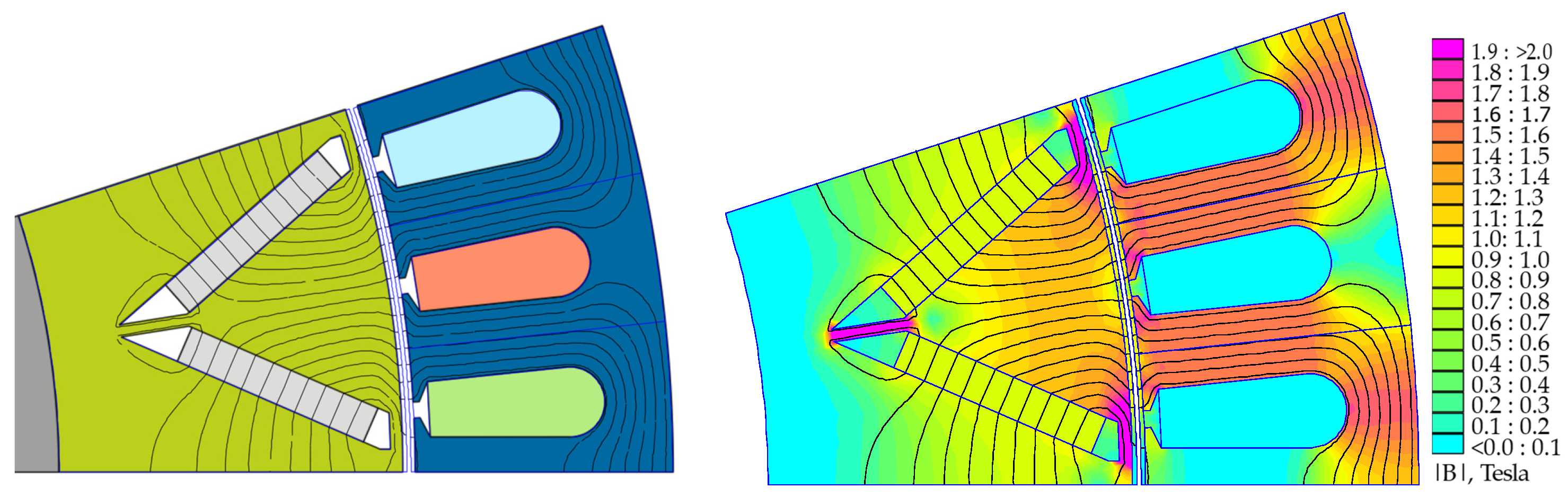
3. Theoretical Analysis of Maxwell’s Forces and Stresses in an Electromagnetic Motor Model

The theoretical analysis of Maxwell forces and stresses in the electromagnetic model was performed for an idealized motor, assuming that the motor is concentric, all pole pairs are symmetrical, and there are no asymmetries in the motor. Such assumptions make it possible to significantly simplify the computational model of the motor as well as reduce the time required for calculations and analysis. However, idealizing the motor model does not make such a model significantly different from the real one, which was made with due care and attention to the concentricity and symmetry of the motor poles. Electromagnetic forces occurring in a permanent magnet motor are Maxwell forces acting on the stator and rotor structure and are concentrated at the iron–air interface [9]. The distribution of Maxwell forces in the motor’s electromagnetic circuit is called Maxwell stress [7]. The stresses can be decomposed into elementary harmonic waves with a frequency f of the force and a wave number ± r describing the spatial frequency of the stress wave. The value of r describes the number of maxima or minima of the stress wave along the air gap [9]. Stress waves with a wave number r = 0 are so-called breathing (pulsating) waves directed mainly to the stretching of the stator package [4,9]. Stress waves with a wave number r ≠ 0 are rotating waves, and their sign determines the direction of rotation of the stress waves. The frequency of the breathing wave is proportional to the smallest common multiple between the number of slots and the number of poles and is given by Equation (1) [9,29].
f r = 0 = L C M ( Q s , 2 p ) f s p = L C M ( Q s , 2 p ) N s 60 ,
where LCM—least common multiple, Qs—number of stator slots, 2p—number of poles, fs—frequency of the stator supply current, and Ns—rotation speed (rpm).
For the analyzed motor type SMwsK280M20, the minimum frequency of the respiratory (pulsating) wave is equal to f(r = 0) = 6fs = Ns or multiples. The minimum respiratory wave frequency in Hz is equal to the rotational speed in revolutions per minute or 60 times the rotational speed in revolutions per second, called H60 or multiples. In symmetrical IPMSMs, there are only a few stress waves [4]. The value of the next smallest wave number can be calculated based on Equation (2) [4]. For the analyzed motor, the next smallest wave number r′ = 20 or multiples of 20, which was confirmed using the Quick Campbell feature of MANATEE software (Figure 2).
r , = G C D Q s n f , 2 p ,
where GCD—greatest common divisor, Qs—number of stator slots, and nf—number of motor phases.
The lowest orders of wave numbers r tend to have a higher radiation efficiency [29], so stress waves with wave number r = 0 must be especially considered in traction drives. It was shown experimentally in the publication [4] and analytically in the work [45] that the main source of noise in traction multipole machines is the breathing mode force r = 0. The motor analyzed in this article is a 2p = 20 multipole machine, and a very large contribution of mode 0 forces to the generated noise is to be expected.

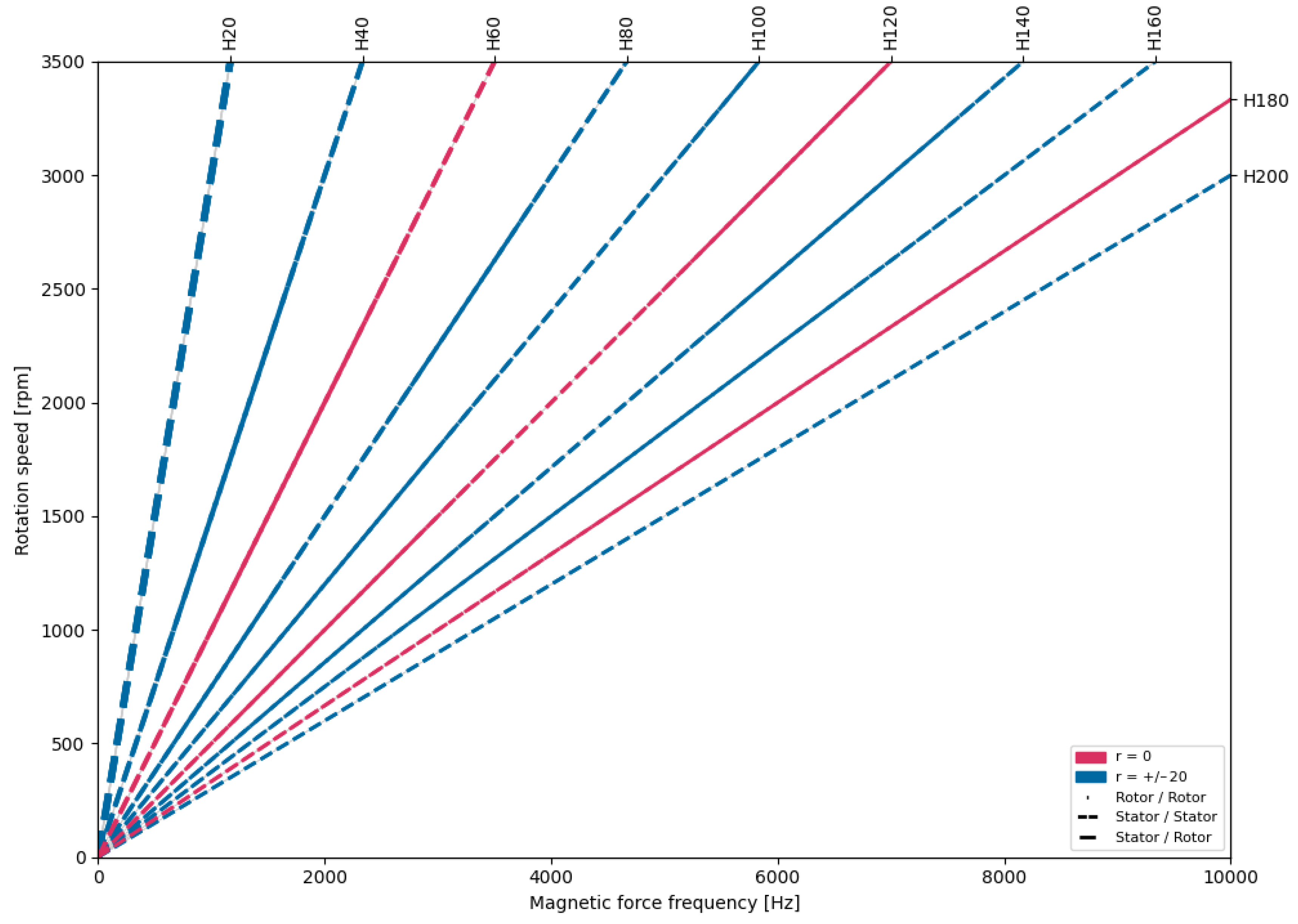
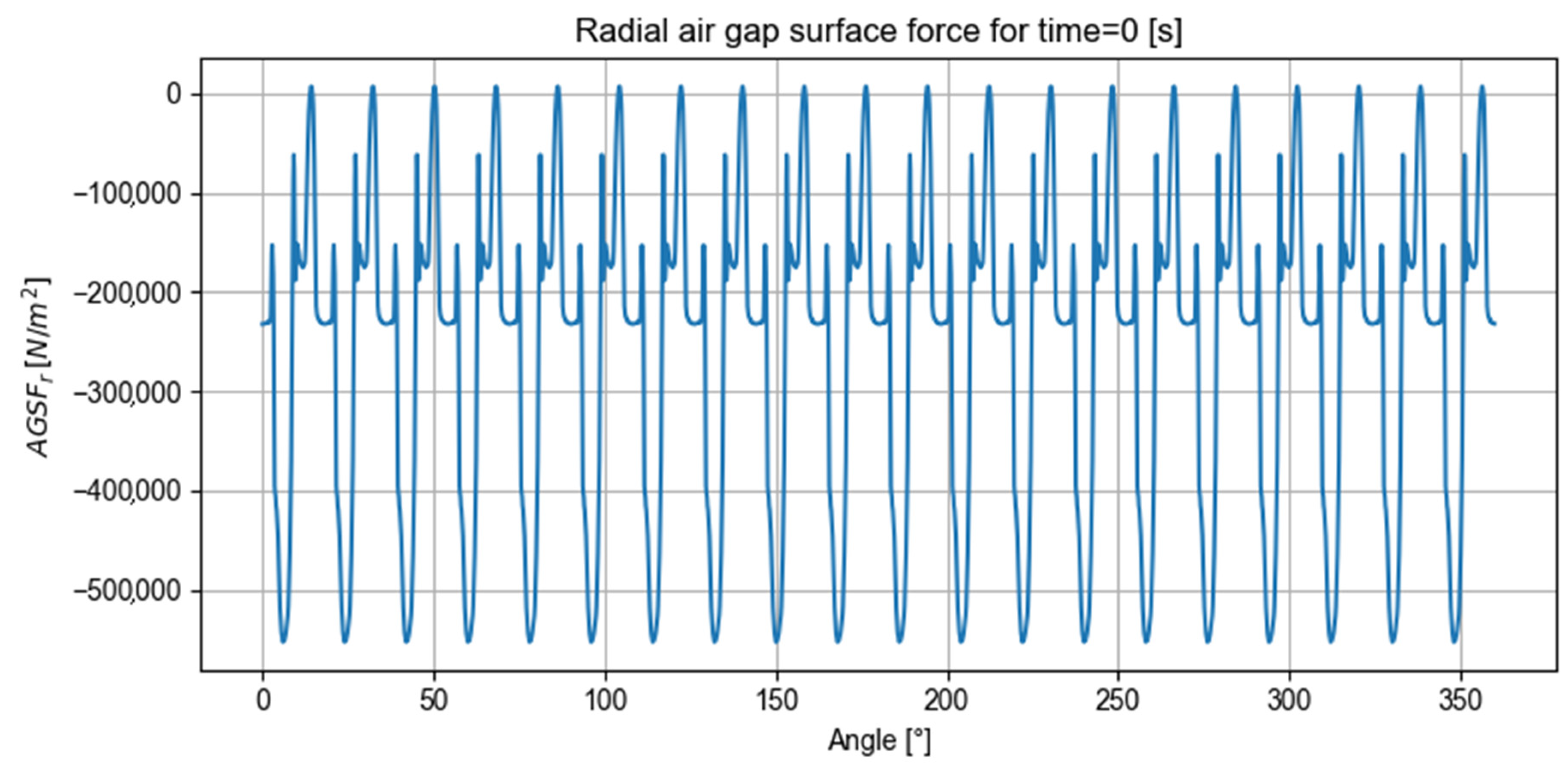
4. Vibroacoustic Analysis of the Electromagnetic Motor Circuit

Vibroacoustic analyses of the motor were performed for the complete motor (with housing and disks) and for the wound electromagnetic circuit of the stator and the complete motor rotor. MANATEE software from EOMYS ENGINEERING was used for vibroacoustic calculations. This software is specialized in electromagnetic and vibroacoustic simulations of electric machines based on finite element calculations [9]. Vibroacoustic calculations were performed for the motor model shown in Figure 1. The calculations were performed in two versions. For the first version, vibroacoustic calculations were performed for a motor without a skew in the stator and without a skew in the rotor. The physically made motor, however, had a stator skew of one slot pitch. Therefore, in the second version of the calculation, a motor model was made with a rotor skew corresponding to the stator skew of the actual motor. In the version of EOMYS software(Version 2.2) used, MANATEE did not allow for vibroacoustic calculations of motors made with a stator skew. The results of the vibroacoustic calculations carried out are shown in Figure 3, Figure 4, Figure 5, Figure 6, Figure 7 and Figure 8. First, the Maxwell pressure that is induced by radial forces coming from the permanent magnets of the rotor and acting on the internal surface of the stator in both models is shown.
In the graphs presented above, which are the result of calculations of the radial air gap Maxwell pressure derived from radial and circumferential flux densities in the motor air gap without skew (Figure 3) and with a rotor skew corresponding to a stator skew of one slot pitch (Figure 4), we can see a significant averaging of the variation in forces, but the skew has little effect on the average values of radial forces; the effect on the maximum pressure present in the air gap over each magnetic pole of the rotor is about 7% in favor of the rotor with a skew. Based on the average force values alone, it is already possible to draw preliminary conclusions that both the skew of the rotor and the stator will have little effect on the acoustic noise values generated by the analyzed motor model. The further analysis of the motor models compared the maximum acoustic power levels of the motors at idle and at rated loads; the results of these calculations are shown in Figure 5, Figure 6 and Figure 7.
Figure 5 and Figure 6 show a comparative analysis of the sound power of the design models with and without rotor magnet skew. They illustrate the total sound emitted in dB(A) at each motor’s no-load operation. The contribution of each structural mode and their overlap are shown. For a motor with no rotor magnet skew, the maximum sound power level is reached at n = 1025 rpm due to the first breathing mode. The next maximum of sound power is reached at 2050 rpm due to the first breathing mode. The third maximum of sound power is due to pulsating radial pressure of the order of 20. For a motor with rotor magnet skew, the maximum sound power level is reached at n = 525 rpm due to the first breathing mode. The next maximum sound power level is reached at 3100 rpm due to a pulsating radial pressure of the order of 20. The third maximum of sound power is reached at 2050 rpm due to the first breathing mode. It can be seen that skewing the rotor has a significant effect on the calculation results, as the calculation shows that skewing the magnets in the rotor or skewing the stator slots by one slot pitch should have a significant effect on the motor noise.
In the case of sound power level analysis for a nominal-load motor model without a skew in the rotor as well as in a motor with a skew in the rotor, both the frequencies of generated vibrations as well as the rotational speeds at which structural excitations occur are very similar. For a rated load, the skew of the rotor already has little effect on the overall noise of the motor. As a result of the motor load, the noise level for both models has risen significantly, as shown in Figure 7 and Figure 8. As for the idle condition and for the motor at a rated load, there is a noise source with a frequency of H60 and a breathing mode. However, for a rated load, this source becomes dominant, and the maximum sound power level is reached at n = 2050 rpm, whose frequency in Hertz is equal to the rotational speed in rpm (2050 Hz). Another maximum in the sound power level is also due to the breathing mode. However, considering the 16 dB decrease in the sound power level for the motor without skewed magnets in the rotor and the 28 dB decrease for the motor with a skewed rotor, it can be concluded that this will have little effect on the overall noise of the motor. Subsequent power maxima at frequencies H180 (Figure 7) and H40 (Figure 8) will also have little effect on the overall motor noise because the amplitude response strongly decreases as the spatial order of the force increases [4].

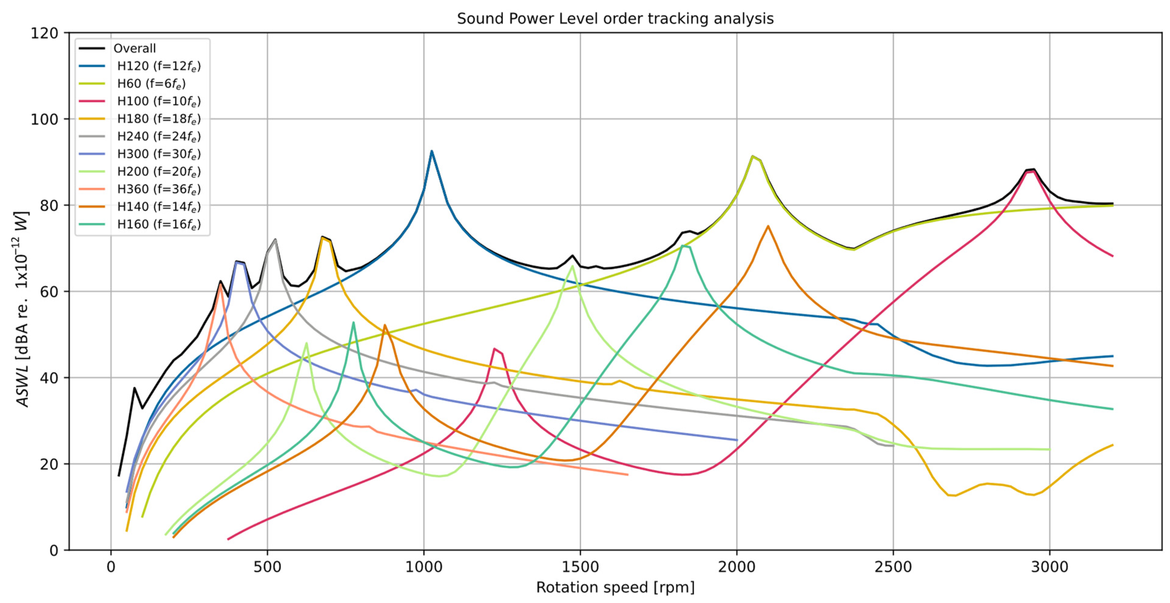
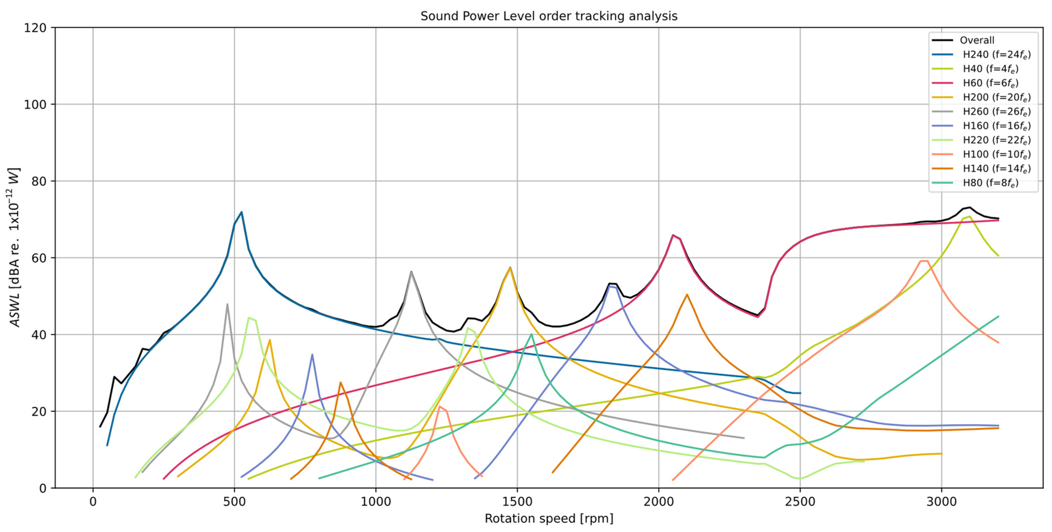
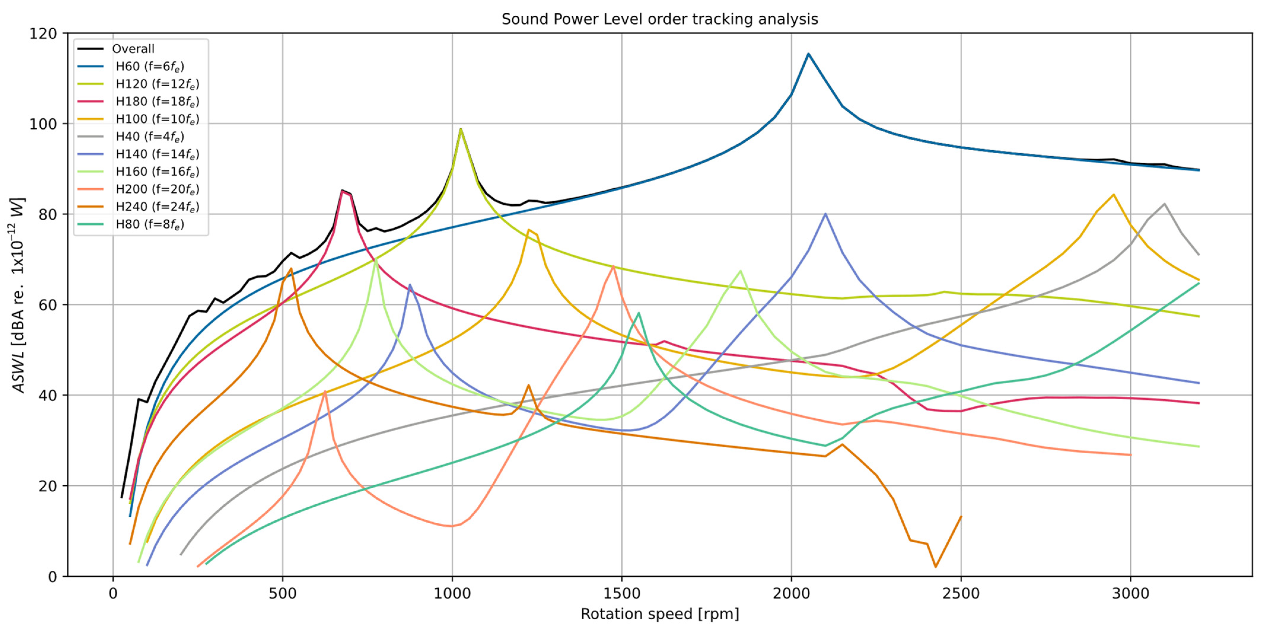
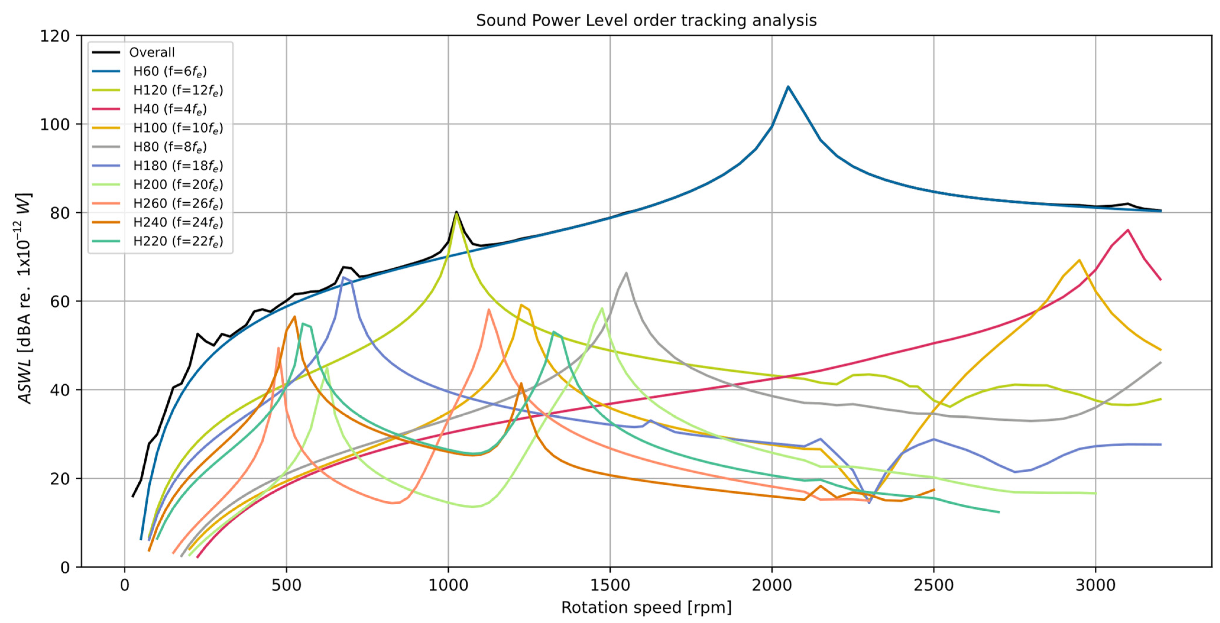
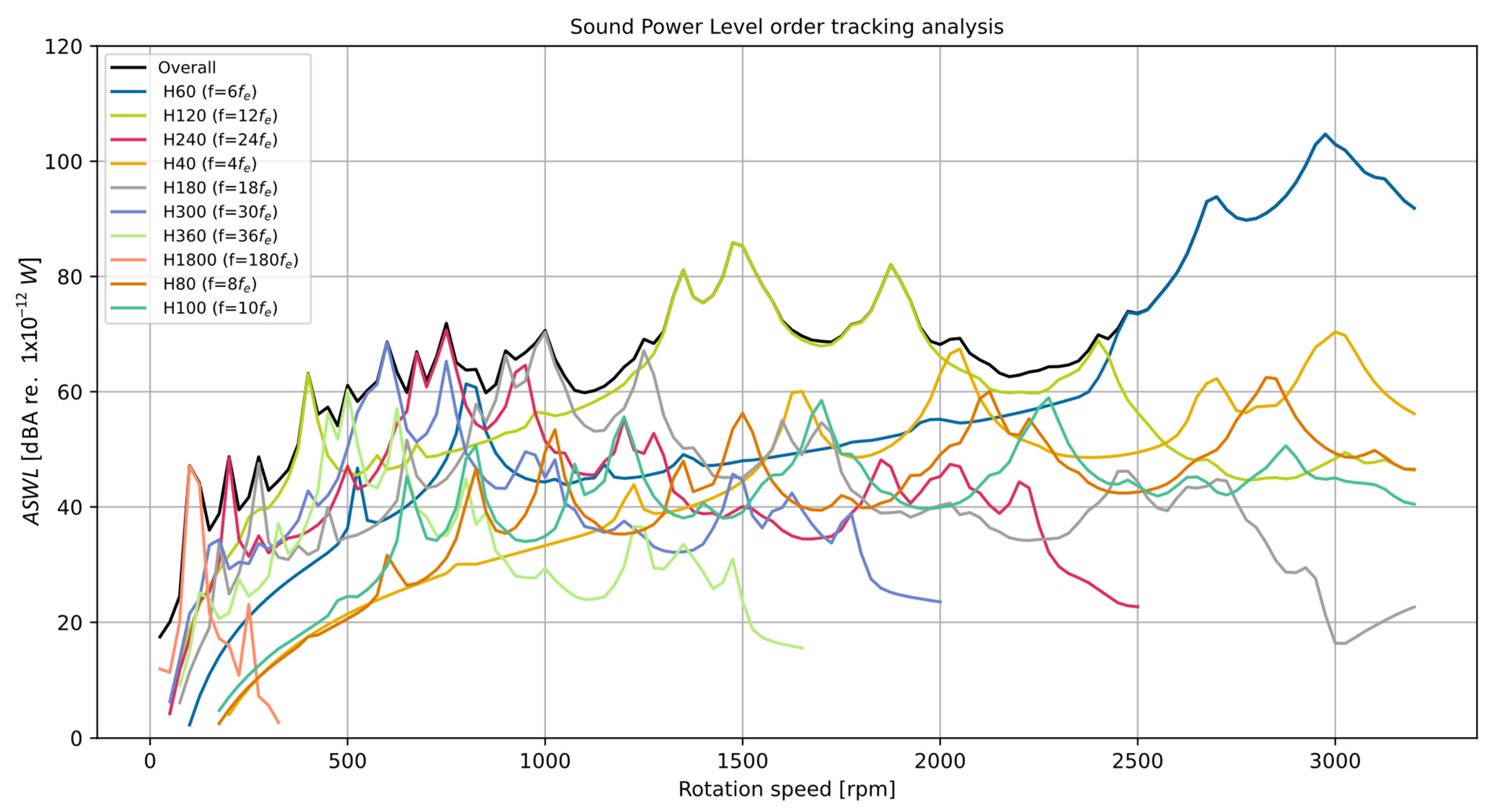
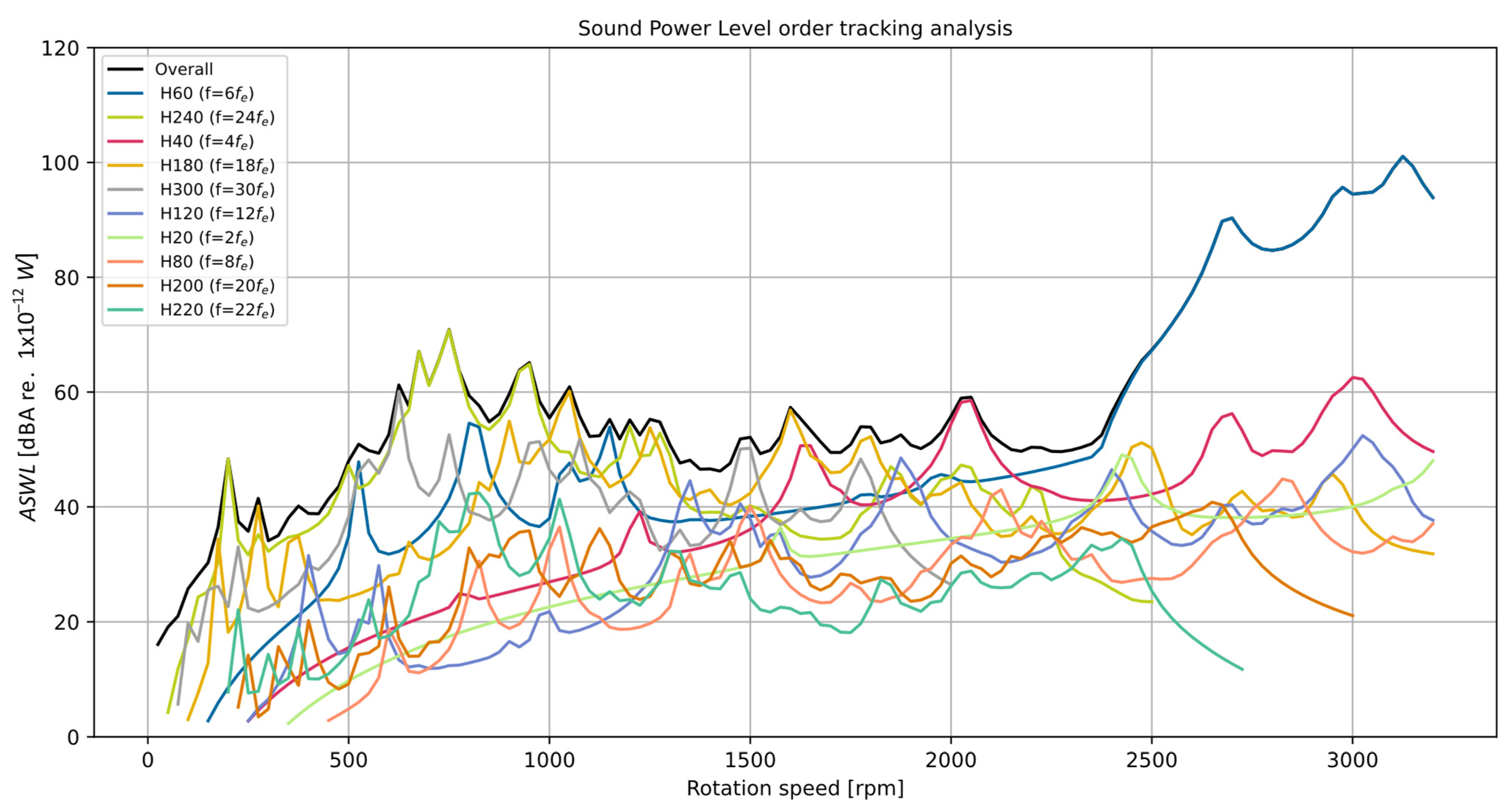
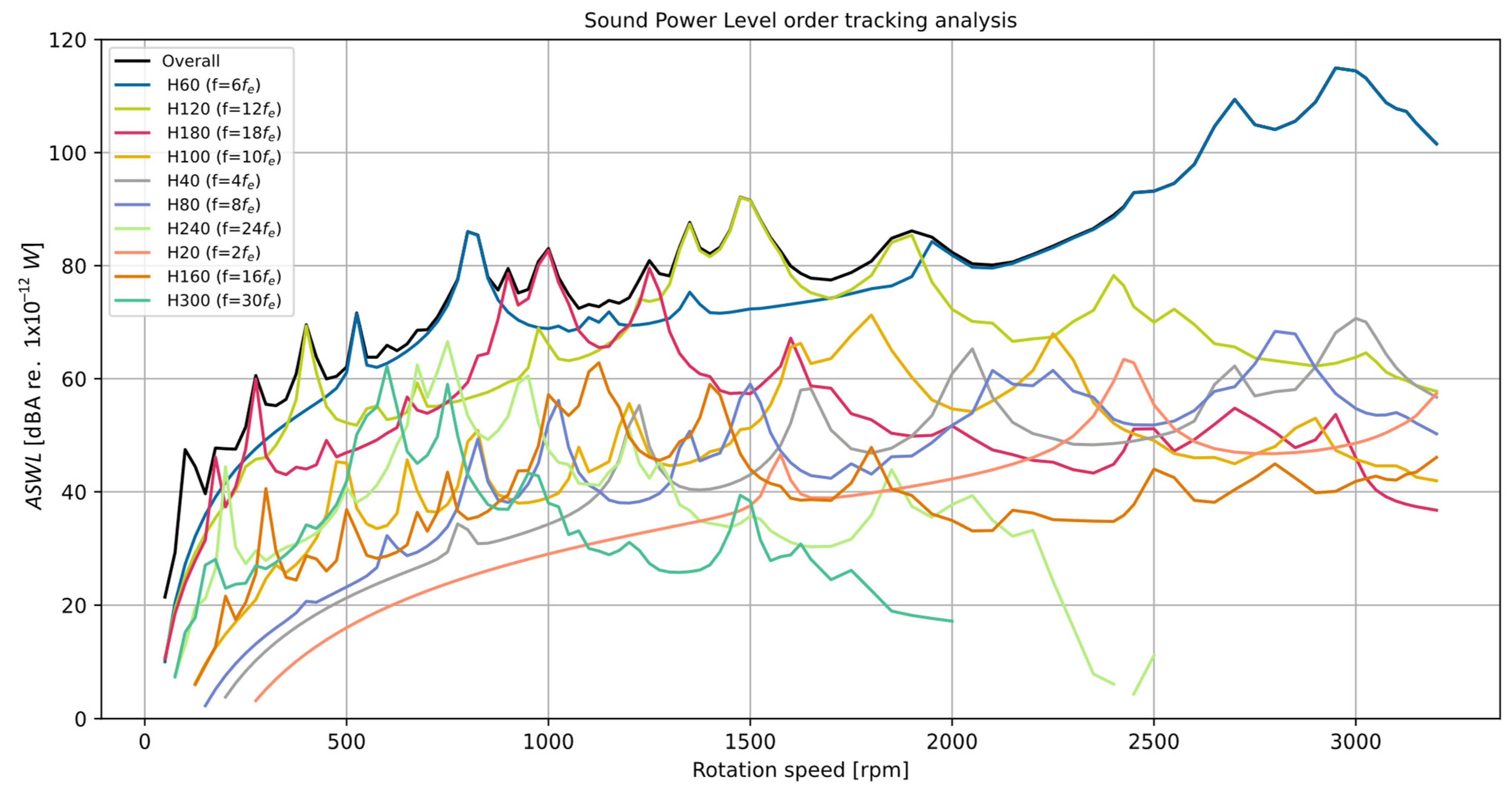
5. Results of the Calculation with the Motor Housing

The next calculation was made for the same motor model, but the motor housing was included in the vibroacoustic calculations. The housing and discs were made of aluminum, and the housing has a liquid cooling system, which was also included in the vibroacoustic calculations. Figure 9 shows the calculation model of the motor housing.
Figure 10 and Figure 11 show the results of vibroacoustic calculations made for a motor operating at idle. The calculations were performed with the program MANATEE version 2.2.4.2, which allows the modal analysis of the complex motor housing to be included in the vibroacoustic calculations. Figure 10 shows the analysis of an idle motor model with a rotor without permanent magnet skew. It can be seen that this analysis is significantly different from the analysis shown in Figure 5, where the motor housing was not included in the calculations. Comparing the two vibroacoustic analyses, we can see how significantly the housing affects the overall noise of the motor. In Figure 5, the frequency H60 was not the dominant frequency; when the housing is included, the frequency H60 is the dominant frequency, and the next frequency of potential noise is H120. Both of these frequencies are breathing modes that were amplified by the housing modal frequencies, the other frequencies of the higher modes were attenuated by the housing, and their overall contribution to the total noise generated by the motor is small. Figure 11 shows a vibroacoustic analysis of a motor with a permanent magnet skew in the rotor. The analysis was performed for a motor operating at idle. Compared to the analysis in Figure 6, it is easy to see that this time the skew of the rotor no longer has such a significant effect on the overall noise of the motor. Comparing the analysis shown in Figure 10 and Figure 11, one can see that one main noise frequency, H60, is the breathing mode frequency, whose Hertzian frequency is equal to the rotor speed in revolutions per minute. The use of the rotor magnet skew has very little effect on this frequency, and, in order to reduce noise, other methods of eliminating this frequency should be considered.
Figure 12 and Figure 13 show further results of vibroacoustic calculations for the motor at a nominal load. Figure 12 shows the vibroacoustic analysis of the motor without a skew of permanent magnets in the rotor, and Figure 13 shows the same analysis but for a motor with a rotor skew. It can be seen that, just as for the no-load operation, the effect of the housing on motor noise, as well as the individual noise frequencies, is very large at the nominal load of the motor. Comparing the analysis of the motor without the housing shown in Figure 7 and Figure 8, one can see that the main and dominant cause of noise is the breathing mode with a frequency equal to H60. For a no-load operation, the amplitude of this frequency was at a speed of 2050 rpm. The inclusion of the housing in vibroacoustic calculations resulted in an amplification of the frequency of H60 and a shift of the amplitude around the maximum speed of the motor (3000 rpm). The effect of introducing a skew in the rotor, similar to what happened when the motor was in a no-load operation, is small. It should also be noted that the frequency of H60 for the maximum speed of the motor is equal to 3000 Hz; such a frequency of sound is very negatively perceived by the human ear, which makes the noise of the motor unpleasant and, at sound power levels over 100 dB(A), difficult to tolerate.

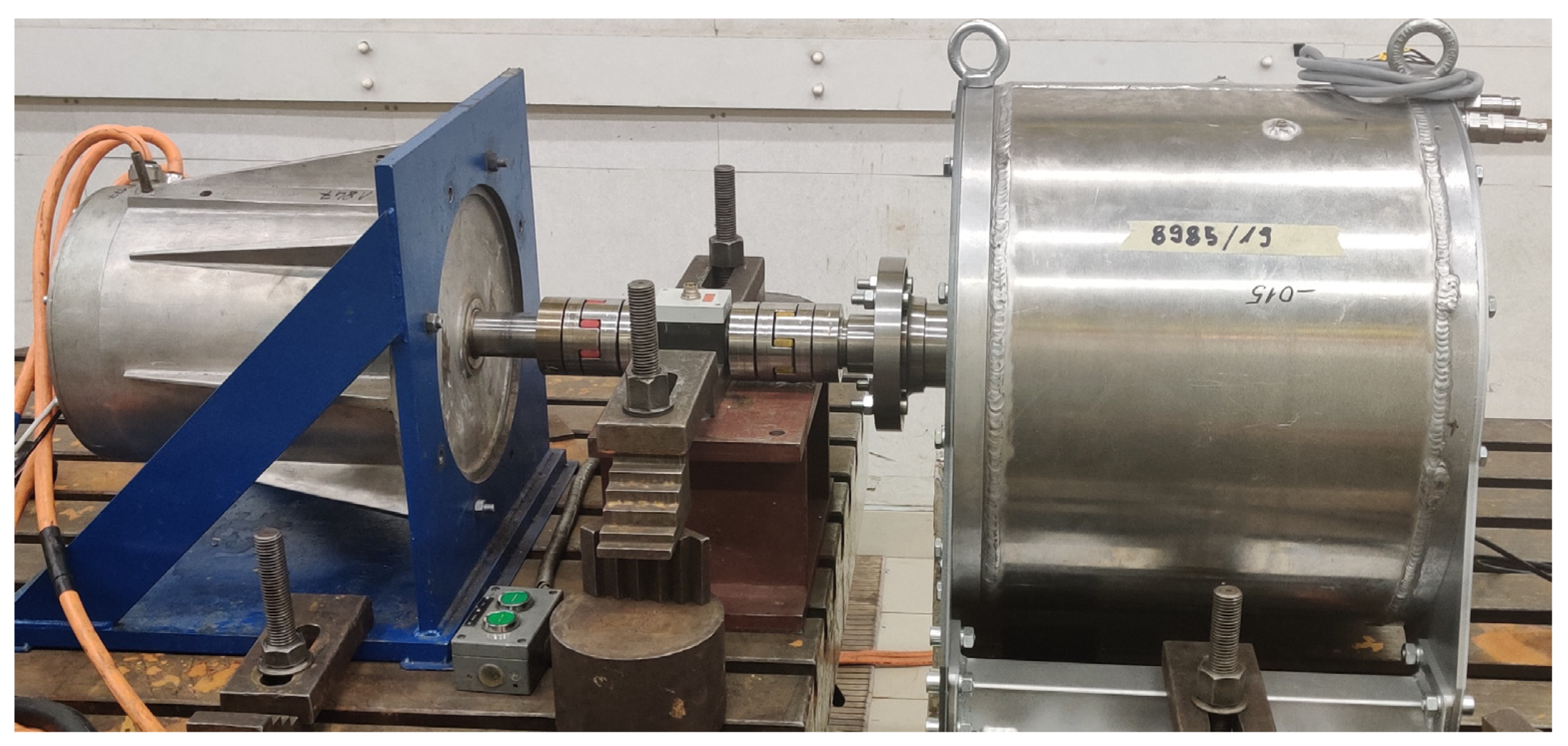
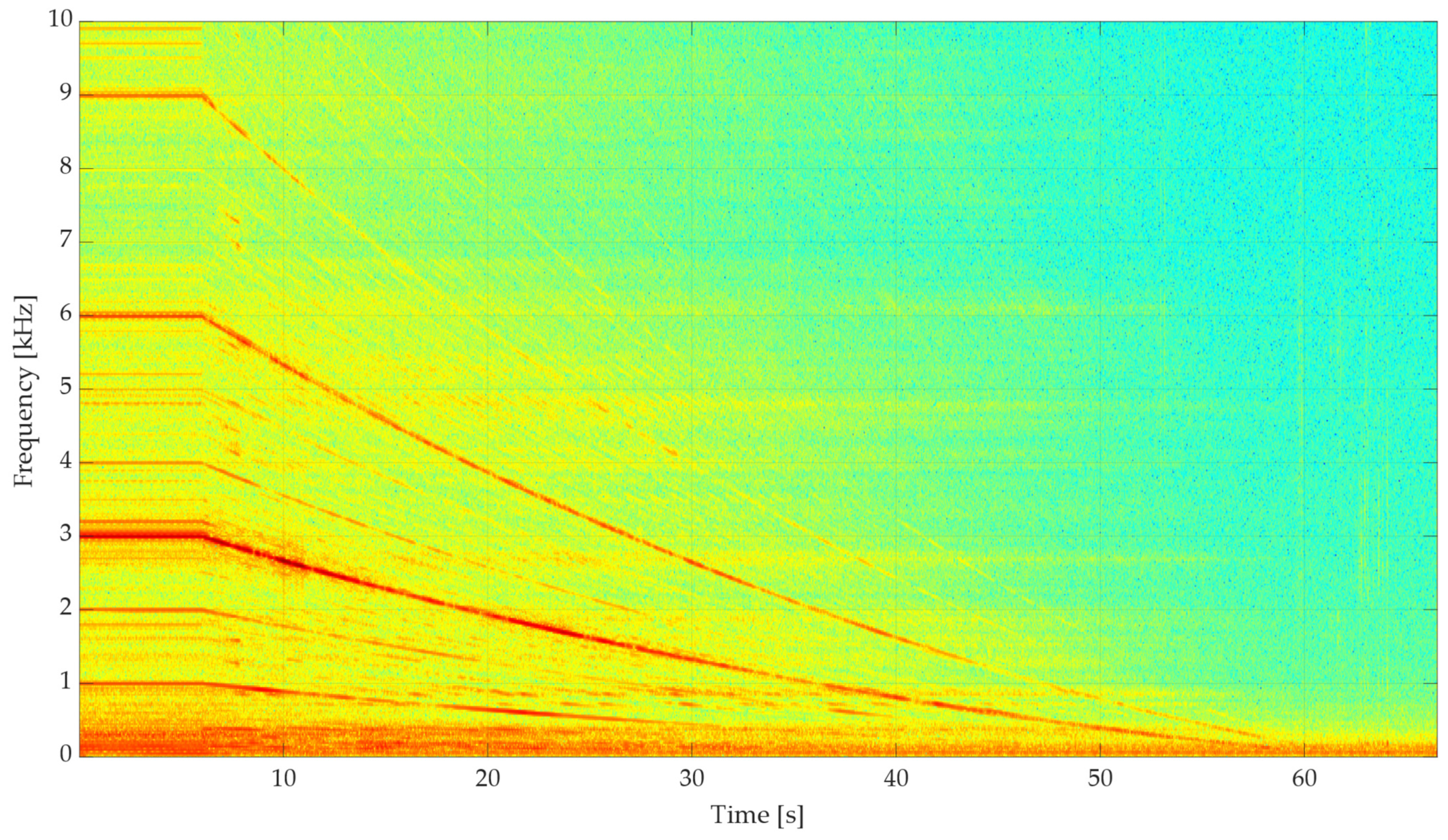
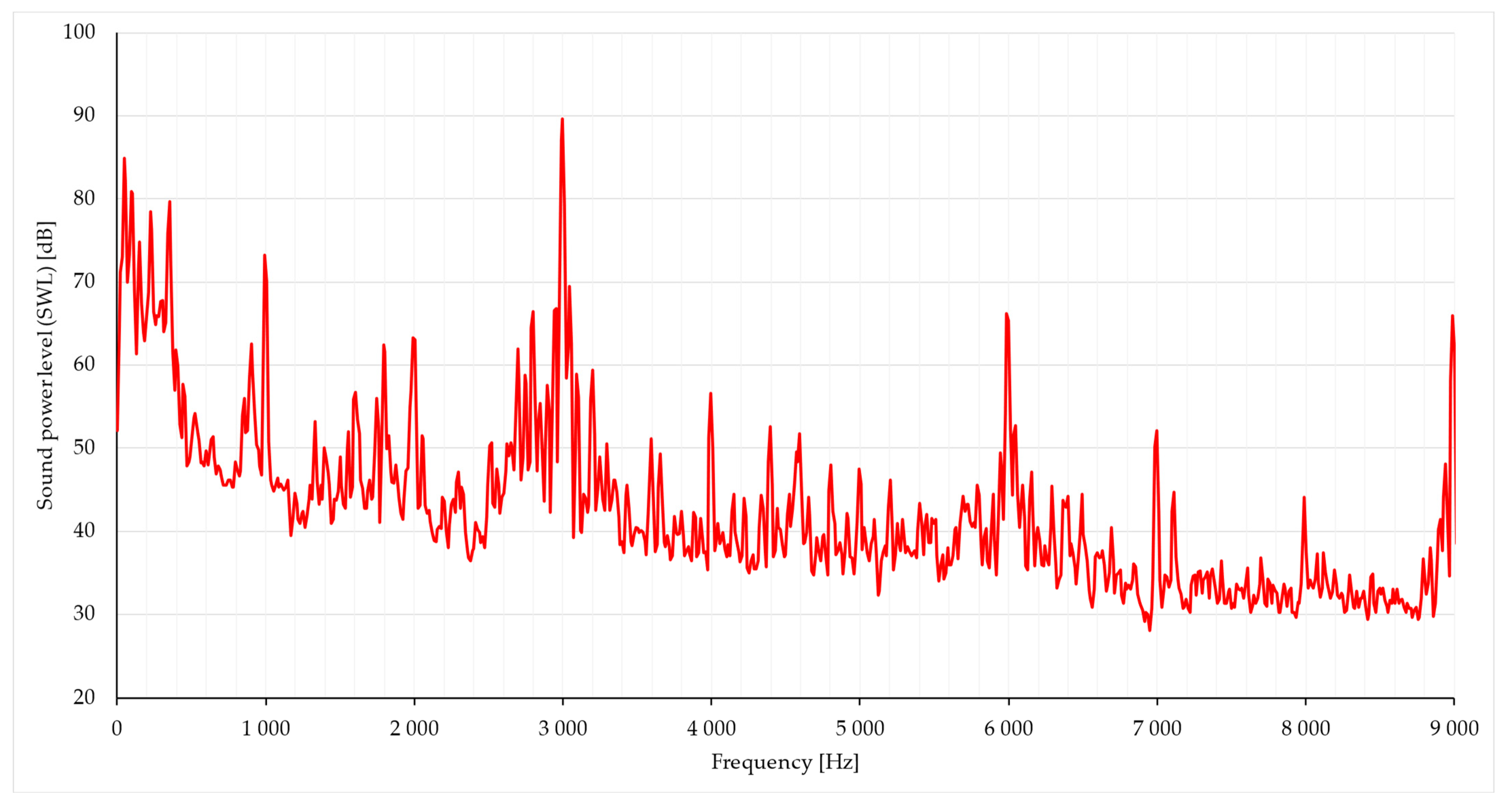
6. Laboratory Test Results of the SMwsK280M20 Motor

After theoretical analyses, the motor was subjected to laboratory tests (Figure 14). First, the noise generated during the runout of the motor from maximum speed to zero was measured and then subjected to spectral analysis. Since the motor under study is a permanent magnet synchronous motor operating in two control zones, runout was performed using an external driving motor. It accelerated the motor to maximum speed and then disabled it. For this type of motor, the ability to perform an outrun at idle was not possible because, in the second control zone, although the torque on the shaft is zero, a significant current in the winding flows, which leads to flux weakening in the air gap to the permanent magnets. On the basis of vibroacoustic calculations and motor runout, rotational speeds were selected, for which measurements were made at nine measurement points (for constant speed). Measurements were made in accordance with the machine standard PN-EN 60034-9:2009 [49].
Based on the analysis of the motor runout (Figure 15), we can see the main noise frequency (with the highest intensity), whose frequency in Hz of the first seconds of the runout (constant speed) equals the rotational speed in rpm (H60 on the Campbell chart). We can also see frequencies that are its multiples of 6 kHz and 9 kHz, respectively, H120 and H180 on the Campbell chart. In addition, we can also see lower frequencies of 1 kHz—H20, which are also derived from the Campbell chart. We can conclude that, on the basis of the analytical analysis, we can already determine the main frequencies of the noise the motor will emit. Unfortunately, based on this analysis alone, we are not able to determine at what motor speed the noise will be greatest.
According to the test program, sound pressure level measurements are always made at given (selected or several) rotational speeds for nine measurement points. Figure 16 and Figure 17 show the analysis for the second measurement point, which is located at an angle of 90 degrees to the axis of the motor shaft (measuring the noise of the side surface of the motor housing; the motor shaft is on the left). Based on these measurements, we can determine in which direction the noise generation is greatest. In addition, based on frequency analysis, we can determine what is causing the noise. Figure 16 and Figure 17 show examples of frequency analysis results for selected speeds. Both figures show a dominant frequency bar equal to the speed in rpm and its multiples. The analysis in Figure 17 shows the normalized noise amplitude for 3000 rpm. Based on this analysis, it can be concluded that the 3000 Hz frequency is dominant over other noise frequencies. The result of the measurements is consistent with the calculations for the housing motor, since there, too, the H60 frequency is the dominant frequency and is the main cause of the motor noise.

7. Discussion

The dynamic expansion of electromobility is making noise source analysis of traction motors important. Vibroacoustic analysis of traction motors, especially high-powered motors, is a necessity on the part of both drive manufacturers and their designers [46]. When analyzing the oscillations and vibrations of traction motors operating over a wide range of speeds, the machine housing and the way the motor is attached to the vehicle frame must also be taken into account. The electromagnetic circuit is a source of vibration and excitation at multiple frequencies, and these frequencies can be both damped and amplified by the motor housing and motor mount. The machine housing itself is not a source; however, it is characterized by resonant frequencies for which it amplifies the excitations of the electromagnetic circuit as well as the noise generated by the motor. The actual electromagnetic circuit of the motor is made as a package of compressed or glued-together individual electrical sheets. Taking into account the package of the stator and housing is very difficult due to the large randomness of the parameters that can affect the noise of the motor [8].

8. Conclusions

Analyzing the potential noise level of a traction motor with permanent magnets makes it possible to eliminate potential problems connected to the electric drive system even before the prototype is manufactured. For this purpose, it is possible to use not only purely analytical methods but also a modern 2D and 3D modeling tool, i.e., MotorCAD or MANATEE (this last one is dedicated for this purpose). In this way, it is also possible to assess not only the level but also the nature of noise. The elimination of components with frequencies consistent with the band of greatest sensitivity of the human ear can have a significant impact on increasing the level of comfort of use of an electric car in which such a drive will be used. The following conclusions can be drawn from an analysis of the authors’ research work:
  • Some of the most important factors affecting motor noise and vibration are the resonance of magnetic force frequencies from permanent magnets, the natural frequencies of the stator and housing, and harmonics from the supply current. The resonance of these frequencies leads to excessive deformation of the stator, which is transferred to the housing and radiates as acoustic noise. Therefore, the material of the motor housing should be properly selected, because as a part of the motor it can both amplify and dampen the noise coming from the stator;
  • Another very important issue affecting the noise level generated in traction motors is the proper selection of the number of slots and poles;
  • Another important factor to consider when designing a motor is the effect of the thickness of the stator yoke, the shape of the stator teeth, and the mass of the winding on the stator natural frequencies;
  • Noise in traction motors can also be caused by the interaction of permanent magnets in or on the rotor with the stator teeth (torque). In many motors, an important part of noise reduction is the use of skewed stator slots or rotor magnets. However, for higher-horsepower high-speed motors operating in the speed range of 0 to 3000 rpm, the effect of the skew on noise is small, and the main source of noise is the 0-mode (breathing) forces, which for this size of machine have frequencies close to the natural vibration of the housing as well as the motor stator.
It Is important to be aware that, in most of the vibroacoustic calculations performed, the final verification of each type of calculation (analytical, FEA 2D, FEA 3D) should be performed on the basis of laboratory tests of the prototype motor and comparison of the obtained test results with the calculations. This approach to vibroacoustic analysis allows us to verify and modify the calculation parameters and materials so that they are as close as possible to the real ones.

Author Contributions

Conceptualization, E.K. and M.M.; methodology, E.K.; software E.K.; validation, E.K. and M.M.; formal analysis, E.K. and M.M.; investigation, E.K. and M.M. writing—original draft preparation, E.K. and M.M.; writing—review and editing, E.K. and M.M.; visualization, E.K. All authors have read and agreed to the published version of the manuscript.

Funding

This research received no external funding.

Data Availability Statement

Data sharing not applicable.

Conflicts of Interest

The authors declare no conflict of interest.

References

  1. Directive (EU) 2019/1161 of the European Parliament and of the Council of 20 June 2019—Amending Directive 2009/33/EC on the Promotion of Clean and Energy-Efficient Road Transport Vehicles. Available online: https://eur-lex.europa.eu/eli/dir/2019/1161/oj (accessed on 10 August 2023).
  2. Hurtley, C.; World Health Organization (Eds.) Night Noise Guidelines for Europe; World Health Organization Europe: Copenhagen, Denmark, 2009; ISBN 978-92-890-4173-7. [Google Scholar]
  3. Commission Delegated Regulation (EU) 2019/839 of 7 March 2019—Amending Regulation (EU) No 540/2014 of the European Parliament and of the Council on the Sound Level of Motor Vehicles and of Replacement Silencing Systems. Available online: https://eur-lex.europa.eu/eli/reg_del/2019/839/oj (accessed on 10 August 2023).
  4. Hofmann, A.; Qi, F.; Lange, T.; De Doncker, R.W. The Breathing Mode-Shape 0: Is It the Main Acoustic Issue in the PMSMs of Today’s Electric Vehicles? In Proceedings of the 2014 17th International Conference on Electrical Machines and Systems (ICEMS), Hangzhou, China, 22–25 October 2014; pp. 3067–3073. [Google Scholar]
  5. Fastl, H.; Zwicker, E. Psychoacoustics: Facts and Models, 3rd ed.; Springer Series in Information Sciences; Springer: Berlin/Heidelberg, Germany; New York, NY, USA, 2007; ISBN 978-3-540-23159-2. [Google Scholar]
  6. Wang, Z.; Zhang, C.; Song, Q.; Fan, J.; Zhang, C. Research on Noise Source Identification of Traction Motor System for Electric Buses Based on Sound Intensity. In Proceedings of the 2008 IEEE Vehicle Power and Propulsion Conference, Harbin, China, 3–5 September 2008; pp. 1–4. [Google Scholar]
  7. Lai, J.C.; Gieras, J.F.; Wang, C. Noise of Polyphase Electric Motors; CRC Press: Boca Raton, FL, USA.
  8. Król, E.; Maciążek, M.; Wolnik, T. Review of Vibroacoustic Analysis Methods of Electric Vehicles Motors. Energies 2023, 16, 2041. [Google Scholar] [CrossRef]
  9. Devillers, E.; Gning, P.; Besnerais, J.L. Effect of Uneven Magnetization on Magnetic Noise and Vibrations in PMSM—Application to EV HEV Electric Motor NVH. In Proceedings of the 2020 International Conference on Electrical Machines (ICEM), Gothenburg, Sweden, 23 August 2020; pp. 1786–1792. [Google Scholar]
  10. Wang, Y.; Gao, H.; Wang, H.; Ma, W. NVH Optimization Analysis of Permanent Magnet Synchronous Motor by Rotor Slotting. Vehicles 2020, 2, 287–302. [Google Scholar] [CrossRef]
  11. La Delfa, P.; Hecquet, M.; Gillon, F.; Le Besnerais, J. Analysis of Radial Force Harmonics in PMSM Responsible for Electromagnetic Noise. In Proceedings of the 2015 Tenth International Conference on Ecological Vehicles and Renewable Energies (EVER), Monte Carlo, Monaco, 31 March 2015; pp. 1–6. [Google Scholar]
  12. Islam, R.; Husain, I. Analytical Model for Predicting Noise and Vibration in Permanent-Magnet Synchronous Motors. IEEE Trans. Ind. Appl. 2010, 46, 2346–2354. [Google Scholar] [CrossRef]
  13. Das, S.; Chowdhury, A.; Paul, S.; Wan, Z.; Islam, R.; Sozer, Y. Experimental and Simulation Based Study of Vibration Prediction in Fractional Slot Permanent Magnet Synchronous Machines. In Proceedings of the 2019 IEEE International Electric Machines & Drives Conference (IEMDC), San Diego, CA, USA, 11–15 May 2019; pp. 1138–1143. [Google Scholar]
  14. Le Besnerais, J. Vibroacoustic Analysis of Radial and Tangential Air-Gap Magnetic Forces in Permanent Magnet Synchronous Machines. IEEE Trans. Magn. 2015, 51, 1–9. [Google Scholar] [CrossRef]
  15. Zuo, S.; Lin, F.; Wu, X. Noise Analysis, Calculation, and Reduction of External Rotor Permanent-Magnet Synchronous Motor. IEEE Trans. Ind. Electron. 2015, 62, 6204–6212. [Google Scholar] [CrossRef]
  16. Kim, K.-T.; Kim, K.-S.; Hwang, S.-M.; Kim, T.-J.; Jung, Y.-H. Comparison of Magnetic Forces for IPM and SPM Motor with Rotor Eccentricity. IEEE Trans. Magn. 2001, 37, 3448–3451. [Google Scholar] [CrossRef]
  17. Chai, F.; Bi, Y.; Chen, L. A Comparison between Axial and Radial Flux Permanent Magnet In-Wheel Motors for Electric Vehicle. In Proceedings of the 2020 International Conference on Electrical Machines (ICEM), Gothenburg, Sweden, 23 August 2020; pp. 1685–1690. [Google Scholar]
  18. Messali, A.; Ghanes, M.; Koteich, M.; Hamida, M.A. A Robust Observer of Rotor Position and Speed for IPMSM HFI Sensorless Drives. In Proceedings of the 2018 IEEE 9th International Symposium on Sensorless Control for Electrical Drives (SLED), Helsinki, Finland, 13–14 September 2018; pp. 90–95. [Google Scholar]
  19. Sarrio, J.E.R.; Ciceo, S.; Martis, C.; Chauvicourt, F. Comparative Study between PMSM Models Used for NVH System-Level Simulation. In Proceedings of the 2019 Electric Vehicles International Conference (EV), Bucharest, Romania, 3–4 October 2019; pp. 1–5. [Google Scholar]
  20. Li, Q.; Fan, T.; Wen, X.; Li, Y.; Wang, Z.; Guo, J. Design Optimization of Interior Permanent Magnet Sychronous Machines for Traction Application over a given Driving Cycle. In Proceedings of the IECON 2017 43rd Annual Conference of the IEEE Industrial Electronics Society, Beijing, China, 29 October–1 November 2017; pp. 1900–1904. [Google Scholar]
  21. Rahman, M.A. High Efficiency IPM Motor Drives for Hybrid Electric Vehicles. In Proceedings of the 2007 Canadian Conference on Electrical and Computer Engineering, Vancouver, BC, Canada, 22–26 April 2007; pp. 252–255. [Google Scholar]
  22. Wu, Q.; Wang, T.; Li, X. Loss-Minimizing Control Based on QP Sequence of the IPMSM Drive Systems for Electric Vehicles. In Proceedings of the 2017 29th Chinese Control And Decision Conference (CCDC), Chongqing, China, 28–30 May 2017; pp. 797–801. [Google Scholar]
  23. Schoenen, T.; Krings, A.; van Treek, D.; De Doncker, R.W. Maximum DC-Link Voltage Utilization for Optimal Operation of IPMSM. In Proceedings of the 2009 IEEE International Electric Machines and Drives Conference, Miami, FL, USA, 3–6 May 2009; pp. 1547–1550. [Google Scholar]
  24. Le Besnerais, J. Fast Prediction of Variable-Speed Acoustic Noise Due to Magnetic Forces in Electrical Machines. In Proceedings of the 2016 XXII International Conference on Electrical Machines (ICEM), Lausanne, Switzerland, 4–7 September 2016; pp. 2259–2265. [Google Scholar]
  25. Yang, Z.; Shang, F.; Brown, I.P.; Krishnamurthy, M. Comparative Study of Interior Permanent Magnet, Induction, and Switched Reluctance Motor Drives for EV and HEV Applications. IEEE Trans. Transp. Electrif. 2015, 1, 245–254. [Google Scholar] [CrossRef]
  26. Kiyota, K.; Kakishima, T.; Chiba, A.; Rahman, M.A. Cylindrical Rotor Design for Acoustic Noise and Windage Loss Reduction in Switched Reluctance Motor for HEV Applications. IEEE Trans. Ind. Appl. 2016, 52, 154–162. [Google Scholar] [CrossRef]
  27. Jung, J.-W.; Lee, S.-H.; Lee, G.-H.; Hong, J.-P.; Lee, D.-H.; Kim, K.-N. Reduction Design of Vibration and Noise in IPMSM Type Integrated Starter and Generator for HEV. IEEE Trans. Magn. 2010, 46, 2454–2457. [Google Scholar] [CrossRef]
  28. Pile, R.; Le Menach, Y.; Le Besnerais, J.; Parent, G. Study of the Combined Effects of the Air-Gap Transfer for Maxwell Tensor and the Tooth Mechanical Modulation in Electrical Machines. IEEE Trans. Magn. 2020, 56, 7502004. [Google Scholar] [CrossRef]
  29. Devillers, E.; Hecquet, M.; Devillers, E.; Le Besnerais, J. A New Hybrid Method for the Fast Computation of Airgap Flux and Magnetic Forces in IPMSM. In Proceedings of the 2017 Twelfth International Conference on Ecological Vehicles and Renewable Energies (EVER), Monte-Carlo, Monaco, 11–13 April 2017; pp. 1–8. [Google Scholar]
  30. Andersson, A.; Thiringer, T. Electrical Machine Acoustic Noise Reduction Based on Rotor Surface Modifications. In Proceedings of the 2016 IEEE Energy Conversion Congress and Exposition (ECCE), Milwaukee, WI, USA, 18–22 September 2016; pp. 1–7. [Google Scholar]
  31. Harries, M.; Woerndle, A.; De Doncker, R.W. Low Vibrations and Improved NVH in Permanent Magnet Synchronous Machines Due to Injection of Flux-Linkage Harmonics. IEEE J. Emerg. Sel. Topics Power Electron. 2021, 10, 1649–1657. [Google Scholar] [CrossRef]
  32. Franck, D.; van der Giet, M.; Hameyer, K. Active Reduction of Audible Noise Exciting Radial Force-Density Waves in Induction Motors. In Proceedings of the 2011 IEEE International Electric Machines & Drives Conference (IEMDC), Niagara Falls, ON, Canada, 15–18 May 2011; pp. 1213–1218. [Google Scholar]
  33. Cassoret, B.; Corton, R.; Roger, D.; Brudny, J.-F. Magnetic Noise Reduction of Induction Machines. IEEE Trans. Power Electron. 2003, 18, 570–579. [Google Scholar] [CrossRef]
  34. Kanematsu, M.; Miyajima, T.; Fujimoto, H.; Hori, Y.; Enomoto, T.; Kondou, M.; Komiya, H.; Yoshimoto, K.; Miyakawa, T. Proposal of 6th Radial Force Control Based on Flux Linkage. In Proceedings of the 2014 International Power Electronics Conference (IPEC-Hiroshima 2014—ECCE ASIA), Hiroshima, Japan, 18–21 May 2014; pp. 2421–2426. [Google Scholar]
  35. Liang, J.; Li, Y.; Mak, C.; Bilgin, B.; Al-Ani, D.; Emadi, A. A Comprehensive Analysis of the Acoustic Noise in an Interior Permanent Magnet Traction Motor. In Proceedings of the 2019 IEEE Energy Conversion Congress and Exposition (ECCE), Baltimore, MD, USA, 29 September–3 October 2019; pp. 3845–3851. [Google Scholar]
  36. Jung, J.-W.; Kim, D.-J.; Hong, J.-P.; Lee, G.-H.; Jeon, S.-M. Experimental Verification and Effects of Step Skewed Rotor Type IPMSM on Vibration and Noise. IEEE Trans. Magn. 2011, 47, 3661–3664. [Google Scholar] [CrossRef]
  37. Pellerey, P.; Favennec, G.; Lanfranchi, V.; Friedrich, G. Active Reduction of Electrical Machines Magnetic Noise by the Control of Low Frequency Current Harmonics. In Proceedings of the IECON 2012 38th Annual Conference on IEEE Industrial Electronics Society, Montreal, QC, Canada, 25–28 October 2012; pp. 1654–1659. [Google Scholar]
  38. Zhu, W.; Pekarek, S.; Fahimi, B. On the Effect of Stator Excitation on Radial and Tangential Flux and Force Densities in a Permanent Magnet Synchronous Machine. In Proceedings of the IEEE International Conference on Electric Machines and Drives, San Antonio, TX, USA, 15–18 May 2005; pp. 346–353. [Google Scholar]
  39. Hwang, Y.-H.; Lee, J. HEV Motor Comparison of IPMSM With Nd Sintered Magnet and Heavy Rare-Earth Free Injection Magnet in the Same Size. IEEE Trans. Appl. Supercond. 2018, 28, 1–5. [Google Scholar] [CrossRef]
  40. Kumagai, S.; Inoue, K.; Kato, T. GA Based Optimized Trajectories of Rotating Speed and D-q Axis Currents for an IPMSM. In Proceedings of the 2018 International Power Electronics Conference (IPEC-Niigata 2018—ECCE Asia), Niigata, Japan, 20–24 May 2018; pp. 1264–1269. [Google Scholar]
  41. Chen, B.; Wu, J.; Sun, Q.; Wu, H.; Zhang, L. FEA-Based Mathematical Modeling and Simulation for IPMSM Drive with Consideration of Saturation and Cross-Coupling Influence. In Proceedings of the 2019 22nd International Conference on Electrical Machines and Systems (ICEMS), Harbin, China, 11–14 August 2019; pp. 1–5. [Google Scholar]
  42. Oh, S.Y.; Cho, S.-Y.; Han, J.-H.; Lee, H.J.; Ryu, G.-H.; Kang, D.; Lee, J. Design of IPMSM Rotor Shape for Magnet Eddy-Current Loss Reduction. IEEE Trans. Magn. 2014, 50, 841–844. [Google Scholar] [CrossRef]
  43. Jung, Y.-H.; Park, M.-R.; Kim, K.-O.; Chin, J.-W.; Hong, J.-P.; Lim, M.-S. Design of High-Speed Multilayer IPMSM Using Ferrite PM for EV Traction Considering Mechanical and Electrical Characteristics. IEEE Trans. Ind. Appl. 2021, 57, 327–339. [Google Scholar] [CrossRef]
  44. Woo, J.-H.; Jung, D.-H.; Choi, J.; Kim, H.; Lee, J. A Study on IPMSM Design, as the Load Motor for the Motor Driving Test of Urban Railway Vehicle through HILS, for Achieving High Power Density. In Proceedings of the 2016 19th International Conference on Electrical Machines and Systems (ICEMS), Chiba, Japan, 13–16 November 2016. [Google Scholar]
  45. Andresen, J.; Vip, S.; Mertens, A.; Paulus, S. Theory of Influencing the Breathing Mode and Torque Pulsations of Permanent Magnet Electric Machines with Harmonic Currents. In Proceedings of the 2020 22nd European Conference on Power Electronics and Applications (EPE’20 ECCE Europe), Lyon, France, 7–11 September 2020; pp. P.1–P.9. [Google Scholar]
  46. Mao, Y.; Liu, G.; Chen, Q.; Zhou, H. Mitigation of Acoustic Noise by Minimize Torque and Radial Force Fluctuation in Fault Tolerant Permanent Magnet Machines. In Proceedings of the 2014 17th International Conference on Electrical Machines and Systems (ICEMS), Hangzhou, China, 22–25 October 2014; pp. 60–64. [Google Scholar]
  47. Nagelkramer, J.; Heitmann, A.; Parspour, N. Application of Dynamic Programming for Active Noise Reduction of PMSM by Reducing Torque Ripple and Radial Force Harmonics. In Proceedings of the 2018 AEIT International Annual Conference, Bari, Italy, 3–5 October 2018; pp. 1–6. [Google Scholar]
  48. Bonneel, P.; Besnerais, J.L.; Devillers, E.; Marinel, C.; Pile, R. Design Optimization of Innovative Electrical Machines Topologies Based on Pyleecan Open-Source Object-Oriented Software. In Proceedings of the 2020 International Conference on Electrical Machines (ICEM), Gothenburg, Sweden, 23–26 August 2020; pp. 2493–2499. [Google Scholar]
  49. PN-EN 60034-9:2009; Rotating Electrical Machines—Part 9: Permissible Noise Levels. Polish Standardization Committee: Warsaw, Poland, 2009.
Figure 1. One magnetic pole of the motor type SMwsK280M20 (made in Pyleecan [48] and Femm).
Energies 16 06018 g001
Figure 2. Campbell diagram for motor SMwsK280M20.
Energies 16 06018 g002
Figure 3. Spatial distribution of the radial air gap Maxwell pressure waveform, for the SMwsK280M20 motor model without rotor magnet skew.
Energies 16 06018 g003
Figure 4. Spatial distribution of the radial air gap Maxwell pressure waveform, for the SMwsK280M20 motor model with rotor magnet skew.
Energies 16 06018 g004
Figure 5. Sound power level order tracking analysis for no-load operation of the SMwsK280M20 motor model without rotor magnet skew.
Energies 16 06018 g005
Figure 6. Sound power level order tracking analysis for no-load operation of the SMwsK280M20 motor model with rotor magnet skew.
Energies 16 06018 g006
Figure 7. Sound power level order tracking analysis for nominal load of the SMwsK280M20 motor model without rotor magnet skew.
Energies 16 06018 g007
Figure 8. Sound power level order tracking analysis for nominal load of the SMwsK280M20 motor model with rotor magnet skew.
Energies 16 06018 g008
Figure 9. Calculation model of the motor housing and CAD model of motor.
Energies 16 06018 g009
Figure 10. Sound power level order tracking analysis for no-load operation of the SMwsK280M20 motor with housing and without rotor magnet skew.
Energies 16 06018 g010
Figure 11. Sound power level order tracking analysis for no-load operation of the SMwsK280M20 motor with housing and with rotor magnet skew.
Energies 16 06018 g011
Figure 12. Sound power level order tracking analysis for nominal load operation of the SMwsK280M20 motor with housing and without rotor magnet skew.
Energies 16 06018 g012
Figure 13. Sound power level order tracking analysis for nominal load operation of the SMwsK280M20 motor with housing and with rotor magnet skew.
Energies 16 06018 g013
Figure 14. Runout analysis of the test motor (from a rotational speed of 3000 rpm).
Energies 16 06018 g014
Figure 15. Runout analysis of the test motor (from a rotational speed of 3000 rpm)–waterfall plot.
Energies 16 06018 g015
Figure 16. Sound power level at 2000 rpm of the SMwsK280M20 motor (for 2 of 9 measurement points).
Energies 16 06018 g016
Figure 17. Sound power level at 3000 rpm of the SMwsK280M20 motor (for 2 of 9 measurement points).
Energies 16 06018 g017
Table 1. Basic mechanical data and electromechanical parameters of the SMwsK280M20 motor.
ParameterUnitValue
Outer diameter of the statormm470
Inner diameter of the statormm382
Length of stator and rotor packagemm170
Number of stator slots -60
Number of poles-20
Type of magnets-N42UH
Thickness of magnet mm6
Maximum powerkW280
Maximum torque Nm2400
Maximum speedrpm3000
Efficiency %96
Weightkg275
Disclaimer/Publisher’s Note: The statements, opinions and data contained in all publications are solely those of the individual author(s) and contributor(s) and not of MDPI and/or the editor(s). MDPI and/or the editor(s) disclaim responsibility for any injury to people or property resulting from any ideas, methods, instructions or products referred to in the content.

