Abstract
Switched reluctance motors (SRMs) face challenges in achieving high performances in terms of the power factor, torque per ampere, and torque ripples. Although several parameters impact their performance, magnetic saliency has a significant impact. This paper presents a study on the influence of the saliency ratio on the performance of switched reluctance motors. A detailed design procedure for a mid-drive electric motor for a high-performance electric bike is presented. A systematic methodology is adopted to estimate the power rating for desired vehicle performance while considering the vehicle’s mechanical and aerodynamic parameters. Additionally, the paper discusses and analyzes the design of two SRM motor configurations with different rotor poles (6/4 and 6/10) while performing magnetostatic analysis for generated torque validation. A parametric study is performed on the 6/10 SRM design for further improvement in the torque profile while keeping the same fill factor and electrical loading. Furthermore, the transient analysis in Ansys Maxwell 2D for both SRMs confirms the designed performance. The results shows that the SRM with higher rotor poles (6/10) is a better choice.
1. Introduction
Mobility is vital to economic progress and high living standards. Improved mobility requires reliable, economical, clean, and most importantly, sustainable transportation. The transportation system relies on fossil fuels, which account for almost one-third of greenhouse gas (GHG) emissions, making it unsustainable and environmental unfriendly [1,2].
The current climate change crisis can be largely attributed to these emissions. Recent observations have shown that climate change is a global phenomenon. The developed nations are making persistent and tenacious efforts to reduce CO2 emissions and other greenhouse gases to limit climate change. One of the critical areas for reducing GHGs is transportation electrification. Some developed nations have indicated their goal of having 100% zero-emission vehicles by 2050.
The idea for electrifying transportation is to use more electricity for applications, including propulsion and non-propulsion loads [3]. Inefficient combustion engines (ICEs) are notorious for their low efficiency (usually below 30%). However, the efficiency of electrical systems is remarkably higher. In most cases, electric motors can achieve efficiency levels of 95% or more when producing power. In addition, compared to mechanical systems, electrical systems are quicker and easier to control.
Additionally, various renewable and carbon-free resources, including wind, solar, and hydro, can be used to produce electrical energy. This scenario compels us to make a paradigm shift in our transport propulsion system to maximize the utilization of natural energy sources. Therefore, it is necessary to know the benchmark specification of traction machines that can deliver competitive performance for IC engines. The following are the requirements for an optimal traction electric machine [4]:
- High peak power and power density;
- High torque density;
- High torques for starting, acceleration, and hill climbing;
- Capacity to produce high power at high speeds for cruising;
- Wide constant power speed range (CPSR);
- Quick dynamic response, enabling rapid and precise adjustments to changing conditions;
- Ability to operate in extreme temperatures and humidity;
- Intermittent overload capability (of twice the rated power);
- Ability to ensure low-frequency service and maintenance requirements, contributing to cost-efficiency;
- Ruggedness and robustness for durability and longevity;
- Fault tolerance and safety;
- Comfort with proper acoustics and noise levels;
- Cost effectiveness.
Efficient, cost effective, and variable speed drives will increase the level of electrification and system efficiency, and reduce operational costs and emissions. The switched reluctance motor (SRM) is a promising candidate for electric vehicle (EV) and hybrid electric vehicle (HEV) propulsion systems due to its simple, rugged construction, extremely high speed, and fault-tolerant nature [5]. The SRM has stator windings and has no excitation on the rotor such as from permanent magnet and rotor winding, allowing it to operate at higher temperatures. Additionally, its simple, durable construction and ability to be designed with smaller dimensions results in lower manufacturing costs. Furthermore, if a fault takes place in one of the phases or windings, the machine can still operate at a reduced load [6]. This is an important advantage that can be beneficial for applications that require continuous operations such as elevators, industrial processes, and EVs. However, the magnetic saturation in the SRM results in a non-linear characteristic of generated torque with a current and rotor position that makes precise torque control challenging. In small and medium-sized EVs, permanent magnet machines contain various grades and quantities of permanent magnets that are technically placed. However, the use of permanent magnets in heavy fleets is restricted due to the rising cost of permanent magnets. Due to their durability and cost-effectiveness, variable reluctance machines, especially the SRM, are promising for the future of the EV industry [7].
Table 1 shows that the SRM is capable of high-speed operation as compared to different motors with higher power densities and reduced sizes and weights. Additionally, the manufacturing of stator and rotor core geometry is not complicated due to structure simplicity. Furthermore, the SRM can function in environments with higher temperatures because it does not have a permanent magnet or winding on the rotor [8]. The SRM can generate power at higher speeds with increased efficiency due to its lack of demagnetizing issues. These characteristics of the SRM are viable and will play a significant role in its future market expansion. Nevertheless, there are still problems to be worked out in the SRM, such as excessive torque ripples, acoustic noise, and low torque density [8]. Due to excessive electrical loading, the motor is driven into saturation, hence torque generation becomes non-linear as a function of the current and rotor position due to the double-salient nature of machines. Hence, this increases control complexity.

Table 1.
Comparison of different machines.
SRM Operation
The SRM is recognized via the combination of stator and rotor poles. The machine’s operation and performance aspects, such as efficiency, average torque, and torque pulsations, are greatly influenced by the number of stator and rotor poles and the number of phases selected. The precise switching of stator phases according to the rotor position is what results in the balanced and symmetrical operation of the machine [9]. Various combinations of stators and rotor poles with different numbers of phases are possible. The desired torque speed and torque ripple characteristics, converter and controller requirements, mechanical tolerances, switching frequency, and rotor position measurement precision are just some factors that will determine the number of rotor poles, stator poles, and phases in a SRM [10].
One of the operational parameters that affect SRM performance is the saliency ratio. The saliency ratio is the ratio of inductance in an aligned ( position to that in an unaligned position ( as shown in (1). The greater this ratio, the better the designed geometry, which will lead to the ability to produce higher torques. In a switched reluctance motor, the rotor consists of salient poles, while the stator has corresponding windings. The saliency ratio plays a crucial role in the motor’s operation, utilizing the magnetic asymmetry between the rotor and stator, and it is defined by Equation (1).
Modern economies require sufficient transportation resources and electric bikes play a crucial role in transportation electrification because they are a major source of transport in many countries across the world. There are some technological and economic issues that need to be examined and resolved before electric scooters can be widely adopted. The main issues with e-scooters are their short driving range, heavy kerb weight, long charging times, and cost. For long-distance travel on a single charge, a motor design with a wide constant power speed range, high energy efficiency, and low weight is therefore necessary. For e-scooters, two different types of motors are available. An in-wheel motor is less expensive to install and takes up less space. Because the hub motor is attached to the rim directly, there are no transmission losses. This motor configuration is suitable for light-performance 2W e-scooters that need high torques at low speeds. Major design limitations for in-wheel motors include their incapability to produce high starting torques for initial acceleration and to achieve high efficiency over a wide speed range. High-performance e-bikes use a mid-drive or an inner rotor motor for increased speed and efficiency that possess a greater capacity for carrying larger loads [1,11].
Singh [11] presents the electrical and mechanical prospects of motor design using an Indian duty cycle for the mechanical load analysis of an electric two-wheeler. After the estimation of the motor power rating, a 2D FEA model is designed that satisfies the torque requirement in conditions of acceleration and hill climbing without analyzing the Avg torque, torque ripple, and losses of the machine. In [12], the author reviews different topologies of the SRM for EV applications and a comparative study is conducted. Three optimized 2D FEA designs with different phase and stator and rotor pole combinations of the SRM, (6/4) 3-φ, (8/6) 4-φ, and (12/8) 6-φ, are analyzed and compared in terms of torque ripple and torque density.
Most of the previous research in which a SRM is designed utilizes different optimization techniques to improve the magnetic circuit without delving into what is going on inside operational parameters that enhance the performance of the motor. In this paper, the 6/10 SRM’s torque is improved using a parametric variation of bore diameter and its impact is analyzed in terms of the magnetic saliency of the machine. A complete design of an inner rotor electric motor from scratch with a drive for a high performance electric bike is presented. The mechanical and electrical prospects of motor design for estimating the required motor power rating are presented based on the calculated power rating and motor geometrical parameters evaluated. The magnetostatic and steady-state analysis is performed using Ansys Maxwell 2D(2022 R1). For improving the average torque and reducing the torque ripples of the 6/10 SRM, the saliency ratio is further investigated by performing parametric analysis with variations in bore diameter and the constraint of keeping the slot fill factor and electrical loading equal to those of the 6/4 SRM. The post-processing results of the FEA are displayed, analyzed, and compared.
2. Motor Design Workflow for Specific EV Application
The initial step in designing the machine is to specify the objectives in terms of power consumption and vehicle performance. The resistances (forces) that a vehicle must overcome can be added to determine roughly how much power is required to move at a particular speed. There are three forms of road resistances that must be considered:
- Vehicles’ natural resistances;
- Counteracting inertial forces caused by moving masses;
- Resistances posed by the track’s profile.
For proper system sizing, one needs to take into account the following resistances [13]:
- Far—air resistance;
- Fr—rolling resistance;
- Fgr—hill climbing resistance/overcoming gravitational pull;
- Fa—acceleration force.
Aerodynamic Resistance Force
This portion of the force is caused by the vehicle’s structure dragging through the air. The aerodynamic drag force () can be defined via Equation (2) as follows:
where ( is the air density, ( is the frontal area including the driver, () is the air drag coefficient, and () is the velocity.
Rolling Resistance Force
Rolling resistance comes largely from tire hysteresis losses, and bearing and gear friction contribute to it. Rolling resistance is relatively constant and speed-independent. Additionally, vehicle mass directly affects it.
The 2W’s frictional forces are mostly determined by its weight, road friction coefficient, and gradient. The force of friction () is defined via Equation (3):
where μ is the rolling coefficient, m is the total weight of the bike and rider, g is the constant of gravity, and is the road slope.
Hill Climbing Resistance
This resistance is caused due to the rising gradient of the track profile during the positive inclination of a road bridge.
The climbing force is defined via Equation (4) as follows:
Acceleration Force
To change the velocity of vehicle, a force needs to be applied which will provide linear acceleration to the vehicle and angular acceleration to wheel, and this is derived from Newton’s third law via Equations (5) and (6):
, I is the inertia of the vehicle, and a is the acceleration. All above mentioned forces and mechanical specification parameters for electric bike are mentioned in Table 2.
Table 2.
Mechanical design specification of the electric bike.
The total force ( due to all forces is equal to the sum of all individual forces, i.e.,
Using the wheel diameter and speed, we can determine the required torque (T) and power (P) at the wheel. Torque and power are expressed as a function of the wheel radius (R), speed (), and total tractive force (), given in Table 3 areas follows:
Table 3.
Resultant forces and power required to overcome these forces.
2.1. SRM Design Factors
One of the major considerations in electric machine design is the selection of the pole configuration and phases. The relative position of the rotor poles towards the stator poles in each phase defines the symmetric and balanced operation of a SRM. By quantifying this relationship, the working SRM configurations are derived. The number of rotor poles ( is related to the number of stator poles ( and the no. of phases (m), which can be expressed as the configuration index () as follows:
where ( is the number of stator poles per phase and is the number of strokes in one mechanical revolution. The configuration index is an integer number, and it can be defined by the designer to calculate the number of rotor poles for the given number of stator poles and number of phases. However, not every rotor pole number within the range of k provides a working configuration. If the configuration index is an integer multiple of any of the prime factors of the number of phases, the SRM configuration will not provide symmetric and balanced conditions. Hence, considering prime values of k, the selected configurations are those of a 6/4 and 6/10 SRM [6].
The approach Is to design a 6/4 pole machine with dimensions such as the outer stator diameter, stack length, no. of turns per pole, diameter of wires, and peak phase currents. Therefore, with the same electrical loading and machine space requirement, a 6/10 SRM is designed and analyzed, and then according to the performance requirement, parametric analysis is conducted to optimize motor performance.
An electrical machine’s design is influenced by a wide-range theory that considers research in the fields of electromagnetism, winding arrangement, magnetic circuit behavior, and winding inductance and resistance. All of these studies, as well as the practical expertise gained by designers and researchers over the years, are considered during the design process of an electric machine. In reluctance machine design, various elements must be considered such as the selection of optimal values for the magnetic flux density in the stator, of rotor poles and yokes, air gaps and polar arcs, and the shape of rotating magnetic field lines. Poor decisions in choosing parameter values can jeopardize the SRM’s final performance [14].
SRM design differs in several ways from that of conventional machines due to the former’s characteristics. The absence of coils, brushes, and empty space between the stator and rotor poles simplify the design. A negative torque output, pulsating torque, and inductance nonlinearity are just a few examples of the various factors that make the modeling of a SRM challenging. SRM CAD designing requires initial calculated values of dimensions that will be used for model creation in 2D.
The starting point Is the calculation of the stator’s inner diameter from a desired specification [14,15].
where is the power produced, is the constant related to the core length, is the duty cycle of the switches, is the desired efficiency, is the constant equal to π2/120, is the saliency ratio, B is the flux density, As is the specific electric loading, and is the rotor speed in rpm.
Stack length ( is determined as a multiple of the inner diameter.
The outer diameter ( and core length are both a multiple of the inner diameter. The ratio of the inner to outer diameter is typically 0.4 to 0.7.
The widths of stator and rotor poles ( are the functions of inner diameter and their respective polar arc values. With this information, Equations (15) and (16) allow us to determine the width of the poles of the stator and the rotor as follows:
where and are pole arc of the stator and rotor pole, respectively.
It is important that the stator yoke be sufficient to accommodate at least 50 percent of the flux density that passes through the stator pole. Therefore, the stator yoke’s thickness ( must be equal to or greater than the width of the stator poles. However, an additional aspect should be addressed to improve solidity and reduce vibration and noise. Hence, the stator yoke’s thickness ( varies in the following range:
Choose values above the minimum. The rotor yoke’s thickness () does not need to be as thick as that of the stator yoke or equal to the minimal value. The thickness of the rotor yoke relative to the width of the stator poles can be specified within the following range:
Equation (19) calculates the stator pole height ( from the outer and inner diameter and the stator yoke’s thickness.
The height of the rotor pole ( can be determined in the same way, and is defined via
Pole Arc
There are conditions in the selection of pole arc angles that are essential for the self-starting requirement and for the shaping of static torque and rotor position characteristics.
This is the minimum value of the pole arc for the self-starting condition.
Equation (23) is used to satisfy that the maximum flux is linked.
This rule is to avoid negative torque generation due to falling inductance instantaneously after the current starts falling to zero. This will allow some time for the current to fall to zero, therefore avoiding further ripples in the torque.
2.2. Analytical Design Approach and Modeling of SRM
The flux linkage of a coil (λ) is linked to the phase current (i) that flows through the coil and its phase inductance (L). Then,
where Rs is the phase resistance and θ is the rotor position.
This includes product rule of a partial derivative, where first, the current (i) is considered to be variable and inductance (L) is considered to be constant. As the inductance (L) is variable concerning the rotor position and time, replacing it in Equation (26) and after solving, the voltage equation of one phase can be expressed as follows [12]:
After taking the derivative of the angular position () linked with the time as the motor angular speed (),
where
Multiplying (29) with the current (i) yields
As
By applying Faraday’s law of electromagnetic induction, the electromotive force (emf) induced can be used to derive the torque equation.
where is the flux linkage, which is a function of the rotor angle and current. Then,
The power (P) developed is given by
The amount of energy stored in a magnetic field (Wm) is given by
The power developed due to variation in the magnetic field is given by
where Pm is difference between the power received from the supply and power due to the change in the magnetic field, and it is given by
whereas the torque (T) is given by (); therefore,
This generated electromagnetic torque, , counters the required frictional force, provides the acceleration torque, and the load torque according to (39).
Here, (J) is the rotor moment of inertia, (Kw) is the machine’s viscous friction constant, and ) is the torque applied to the rotor via an external load.
2.3. Losses in SRM
In switched reluctance machines, copper losses are a dominant loss type due to the electrical resistivity of the stator’s winding [16].
is the phase resistance, and IA, IB, and IC are the currents of respective phases.
Other types of loss include hysteresis and eddy current loss in the core. Hysteresis loss is caused due to molecular friction in a ferromagnetic material, under alternating magnetic fields.
η is the Steinmetz hysteresis coefficient, Bmaxn is the maximum flux density, f is the frequency of magnetic reversals per second (Hz), and V is the volume of the magnetic material.
Eddy current loss is caused due to the induction of an eddy current in the core and conductors held in the magnetic field.
where Pe is the eddy current loss (W), Ke is the eddy current constant, B is the flux density (Wb/m2), f is the frequency of magnetic reversals per second (Hz), t is the material thickness (m), and V is the volume (m3).
Core loss is the sum of hysteresis ( and the eddy current loss.
Total loss is the sum of the copper loss and core loss.
The desired specification of motor and machine data is mentioned in Table 4 and Table 5 respectively while stator and rotor geometrical parameters are presented in Table 6.
Table 4.
Specification of motor and desired performance.
Table 5.
Motor specification and machine data.
Table 6.
Dimensions of stator and rotor lamination.
The design of an electric motor requires the determination of initial motor sizing considering geometrical constraints, the selection of stator and rotor core material, an analysis of the electromagnetic field, post-processing to calculate the static characteristics of the machine, and the satisfaction of static and dynamic requirements and motor performances as shown in Figure 1.
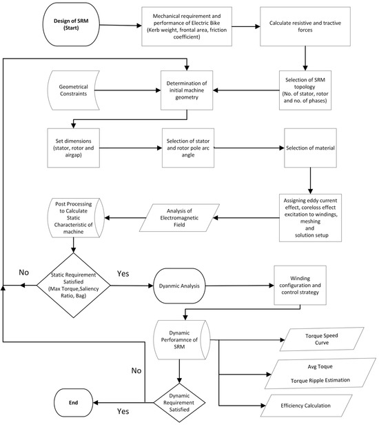
Figure 1.
Framework of the adopted design methodology.
3. Two-Dimensional FEM Result Analysis
3.1. Magnetostatic Analysis
To ensure that the designed machine can satisfy the desired specifications, magnetostatic analysis is carried out in which magnetic field behavior such as the maximum magnetic flux density, magnetic field strength, and magnetic flux lines are analyzed in an aligned position at the peak current to check if the machine is not driven into saturation. Basically, it considers the interaction between magnetic materials, electric currents, and magnetic sources, such as permanent magnets or electromagnets. To carry this out, stator and rotor geometries are created, and coil terminal excitation is assigned to one phase. These coils are then provided with a peak phase current, the rotor is rotated from unaligned to aligned positions, and fields are recorded. Figure 2 shows the maximum magnetic flux density in stator and rotor poles in an aligned position. This value is around 1.5 Tesla which is less than the saturation limit of the material (Cogent Power M350-50A).
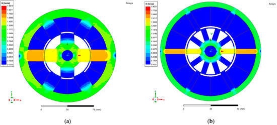
Figure 2.
Magnetic loading in aligned position with peak phase current of designed 2D geometry of (a) 6/4 SRM and (b) 6/10 SRM.
Figure 3 shows magnetic characteristic (MC) plots of designed motors. MC refers to the relationship between the magnetic flux linkage and the rotor position or phase current. It describes how the magnetic flux varies with respect to the rotor position or phase current. These plots are useful for understanding the motor’s performance and behavior. In Figure 3a,c flux linkage vs. current plot in two extreme rotor positions is measured to determine the saliency ratio. In a good design, the saliency ratio varies between 3 and 5.
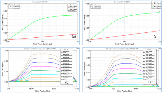
Figure 3.
Magnetic characteristics plots of designed motors’ (a,c) flux linkage vs. current in aligned and unaligned position. (b,d) Static torque at different currents and in different rotor positions of 6/4 and optimized 6/10 SRM.
It is noticeable that in an unaligned position, the slope is linear because saturation does not occur. In the aligned position, the slope of the line becomes horizontal because saturation starts in the machine and magnetic loading is not proportional to electrical loading. The area enclosed under these curves is what is called co-energy and this is proportional to the torque generated as mentioned in (35). Therefore, the 6/4 SRM has a larger area and hence it can result in more generated torque than can the 6/10 SRM.
After this, static torque analysis is conducted to check how much torque is generated as the rotor position is varied for different values of current as shown in Figure 3. This shows that the torque rises linearly from the unaligned position to the start of poles overlapping positions and then it levels off and starts to decrease until it becomes zero in an aligned position.
As depicted in Figure 3 the 6/10 SRM with the same outer stator dia, stack length, bore dia, number of turns, and peak current is unable to generate a desired torque that is greater than 9.6 Nm due to the low saliency ratio and rotor pole pitch gap. To overcome this issue with the same space requirements and electrical loading, the design variable chosen for parametric analysis is bore diameter, taking the advantage of the large slot area of the 6/10 SRM that results in a low sff.
Parametric Analysis
Parametric analysis provides valuable insights into the impact of different design variables on electromagnetic systems. The strategy to improve the torque of the 6/10 SRM is to conduct parametric analysis with the same electrical loading and one of the mechanical design constraint parameters, the slot fill factor. Figure 4 shows that bore diameter is varied to the point where both machines’ sff values become same, i.e., 0.5, and the resultant saliency ratio and static and avg torque are mentioned in Table 7 which is a comparison of the performance of designed motors
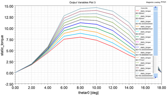
Figure 4.
Parametric result- torque variation with bore dia as a function of rotor position.
Table 7.
Impact of bore dia variation on saliency ratio and resultant output torque.
According to (45), as we kept all variables constant, varying the bore dia results in changes in the static output generated torque. The saliency ratio increases due to an increase in the inter-polar gap of the stator, resulting in more time for the current to fall to zero when the stator pole is switched off, hence reducing the value of flux linkage in the unaligned position before next-phase energization and causing the saliency ratio to increase. Figure 5 illustrates the static torque generated with an increased torque of the larger bore dia according to (45).
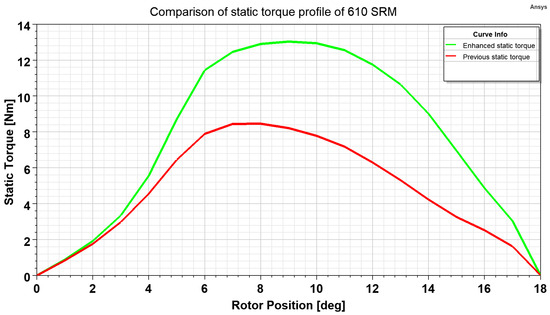
Figure 5.
Comparison of static torque profile of 6/10 SRM.
3.2. Steady State Analysis
After magnetostatic analysis, it is confirmed that the motor design can generate the required torque. Now, checking motor dynamic performance at the rated speed is necessary for detailed motor performance evaluation. Both winding arrangement and the control strategy are implemented along with converter interconnection with the electromagnetic model of the motor. The asymmetric bridge converter topology is built into the maxwell circuit editor, as shown in Figure 6, that has two switches and two diodes per phase configuration. The conduction time and advance angle of the pulse trigger circuit for the gates are setup at the rated speed. The period of the electrical cycle is determined according to the rotor pole pitch angle rotation of the rotor. The model is simulated at the rated speed and the performance is determined.
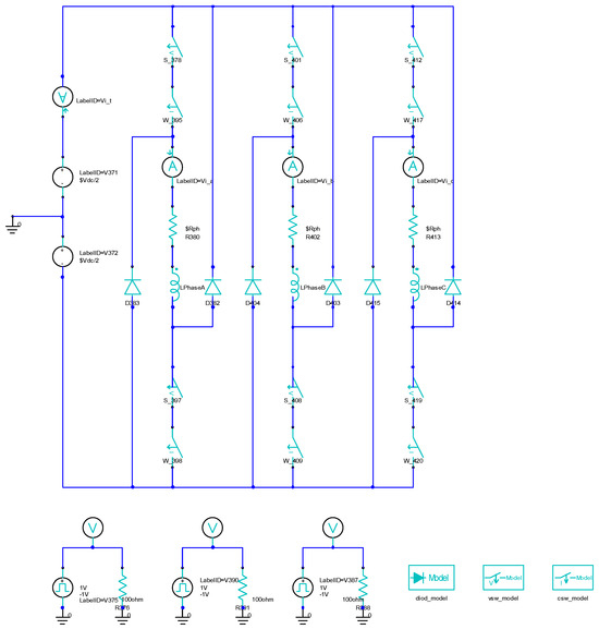
Figure 6.
Asymmetric bridge converter with switching circuit for SRM.
As seen in Figure 7, the 6/4 SRM has a reduced avg torque and increased torque ripple compared to those of 6/10 SRM. Torque ripples in a SRM are classified into two categories: those caused by the high-frequency switching of phases via the hysteresis controller and those created due to the commutation of phases. These later cause a sharp dip in the torque profile and hence largely impact machine performance. The reason for this mainly depends on the machine configuration, i.e., the number of rotor and stator poles and phases. When the phase current reaches the reference current, then phases are turned off and on repetitively according to the hysteresis band until they are in the turnoff position, which results in low-magnitude torque ripple. This ripples affect the average torque and hence the power generated at that speed is also slightly less for the 6/4 SRM than the desired value compared to those of the 6/10 SRM. Figure 8 shows a dynamic analysis in terms of the torque speed profile of the designed motors. Briefly, the 6/4 SRM has a lower count and higher speed capability. The first region is a constant torque region up to the rated speed. This region is mostly operated with a hysteresis controller where the current level is maintained at the reference value via varying duty cycles with constant conduction angles; hence, the torque is kept constant. In the constant and falling power region, single-pulse control is implemented. The voltage remains constant in both regions while the conduction angle varies in the constant power region.
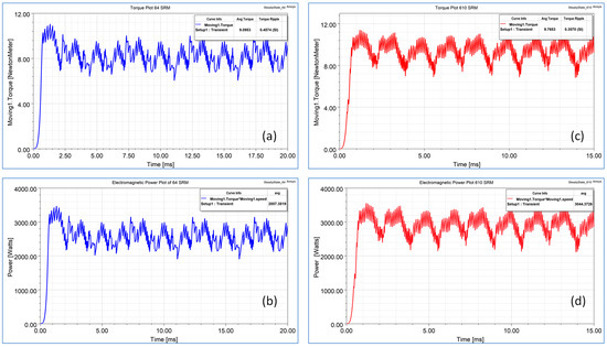
Figure 7.
Avg torque and torque ripple (a,c) and avg power (b,d) at rated speed of 6/4 and 6/10 SRM.
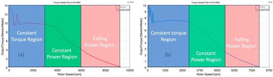
Figure 8.
Torque speed plot of (a) 6/4 SRM and (b) 6/10 SRM.
The stator and rotor in a SRM are typically made of non-oriented soft magnetic electrical steel. Since the stator and rotor cores of a SRM can be exposed to high frequencies, it is often desirable to use electrical steel with lower losses. In addition, it is always desired to use core material with a high-saturation flux density to improve the torque density and power factor. Like in other types of electric machines, the stator and rotor in SRMs are typically laminated to reduce eddy current losses. Thin laminations are preferred as they generate lower core losses and, therefore, achieve higher efficiency. Figure 9 shows that copper losses are the dominant loss type at the rated speed while next come eddy current and hysteresis losses. It is worth noticing that core losses increase in the 6/10 SRM due to the increased switching frequency of the phase current around 500 Hz at the rated speed compared to that around 200 Hz for the 6/4 SRM. Reduced core losses at lower speeds in the presence of less pole rotors result in higher efficiency as shown in Figure 10.
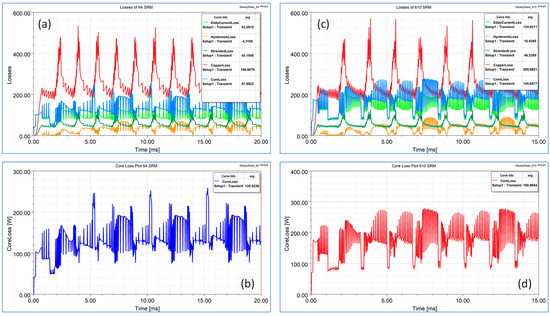
Figure 9.
(a,c) Copper loss, eddy current loss, hysteresis loss, and stranded losses; (b,d) core loss of 6/4 and 6/10 SRM.
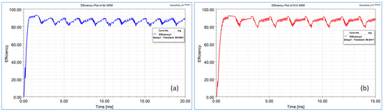
Figure 10.
Efficiency plot of (a) 6/4 SRM and (b) 6/10 SRM.
At a low speed, the current drawn is high; hence, larger copper losses cause reduced efficiency. As speed increases, the current drawn reduces but the switching frequency increases; hence, copper losses decrease more sharply than iron losses increase and efficiency improves at higher speeds. Figure 9 shows that the efficiency of the 6/4 SRM is around 2.5 pc greater than that of the 6/10 SRM due to the reduced core losses.
Figure 11a,b show the phase current plots of both machines. The RMS current value for the 6/10 SRM is low due to the decreased switching time of phase energization per phase, resulting in lower current density in the winding. This winding carrying the current results in flux production; see Figure 11c,d. Due to the increase in the stator pole width of the 6/4 SRM, there is more flux linkage than that of the 6/10 SRM but as the number of rotor poles is less, it results in a more pulsated torque waveform and hence poor torque quality. Table 8 presents operational parameters at rated speed and Table 9 shows 6/4 and parametrized 6/10 SRMs performance comparison
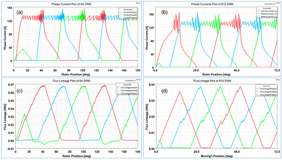
Figure 11.
(a,b) Phase current. (c,d) Flux linkage plot of 6/4 and 6/10 SRM.
Table 8.
Operational parameters in rated operation.
Table 9.
Comparison of performance of designed motors.
4. Conclusions
In this paper, a saliency ratio-based switched reluctance motor design methodology is presented for the design of a high-performance electric bike. First, the mechanical aspect of a bike is determined to the calculate motor power rating according to the desired vehicle performance. Then, SRM dimensions, winding turns, and wire diameters are determined by considering the forced air cooling method with permissible current densities for reliable continuous operation in rated condition. Based on the proposed method, two designs of SRM configurations, 6/4 and 6/10, are presented while keeping the same space requirement constraints, electrical loading, and slot fill factor parameters. Magnetostatic analysis is performed, and magnetic loading and static torque are determined. Due to the reduced saliency ratio, parametric analysis is carried out by varying bore diameter to optimize the average torque output of the 6/10 SRM while maintaining the same slot fill factor and electrical loading. The results showed that the 6/10 SRM is 10% lighter in weight, has its torque density increased by 7.7%, and has its torque ripples reduced by 22% in contrast to the 2.7% reduction in efficiency at the rated speed compared to that of the 6/4 SRM. A relative comparison of both SRMs’ performances suggests that the 6/10 SRM is a better choice due to it being lighter in weight, its enhanced average torque, and its reduced torque ripple, as well as it meeting the required output power. However, this comes at the expense of efficiency, with this being slightly reduced due to increased core losses compared to that of the 6/4 SRM. Implementing an advanced control strategy might reduce this difference in efficiency.
Author Contributions
Conceptualization, A.G.; Methodology, H.A.K.; Software, A.G.; Formal analysis, A.G. and H.R.; Investigation, H.A.K. and H.R.; Resources, H.A.K.; Writing – original draft, A.G.; Writing—review & editing, H.A.K. and H.R.; Visualization, H.A.K. and H.R.; Supervision, H.A.K. All authors have read and agreed to the published version of the manuscript.
Funding
This work was supported in part by the open Access Program form American University of Sharjah. This article represents the opinions of the author(s) and does not mean to represent the position or opinions of the American University of Sharjah.
Conflicts of Interest
The authors declare no conflict of interest.
References
- Bilgin, B.; Magne, P.; Malysz, P.; Pantelic, V.; Preindl, M.; Korobkine, A.; Jiang, W.; Member, S.; Lawford, M.; Member, S.; et al. Making the Case for Electrified Transportation. IEEE Trans. Transp. Electrif. 2015, 7782, 4–17. [Google Scholar] [CrossRef]
- Kiyota, K.; Chiba, A. Design of Switched Reluctance Motor Competitive to 60-KW IPMSM in Third-Generation Hybrid Electric Vehicle. IEEE Trans. Ind. Appl. 2012, 48, 2303–2309. [Google Scholar] [CrossRef]
- Anvari, B.; Toliyat, H.A.; Fahimi, B. Simultaneous Optimization of Geometry and Firing Angles for In-Wheel Switched Reluctance Motor Drive. IEEE Trans. Transp. Electrif. 2017, 4, 322–329. [Google Scholar] [CrossRef]
- Bostanci, E.; Moallem, M.; Parsapour, A.; Fahimi, B. Opportunities and Challenges of Switched Reluctance Motor Drives for Electric Propulsion: A Comparative Study. IEEE Trans. Transp. Electrif. 2017, 3, 58–75. [Google Scholar] [CrossRef]
- Xu, Z.; Li, T.; Zhang, F.; Wang, H.; Lee, D.-H.; Ahn, J.-W. Characteristics Evaluation of a Segmental Rotor Type Switched Reluctance Motor with Concentrated Winding for Torque Density and Efficiency Improvement. Energies 2022, 15, 8915. [Google Scholar] [CrossRef]
- Emadi, A.; Jiang, J.W.; Bilgin, B. Switched Reluctance Motor Drives Fundamentals to Applications, 1st ed.; CRC Press Taylor & Francis Group: Boca Raton, FL, USA, 2019; ISBN 9780203729991. [Google Scholar]
- Xu, Z.; Li, T.; Zhang, F.; Zhang, Y.; Lee, D.-H.; Ahn, J.-W. A Review on Segmented Switched Reluctance Motors. Energies 2022, 15, 9212. [Google Scholar] [CrossRef]
- Chiba, A.; Kiyota, K. Review of Research and Development of Switched Reluctance Motor for Hybrid Electrical Vehicle. In Proceedings of the 2015 IEEE Workshop on Electrical Machines Design, Control and Diagnosis, WEMDCD 2015, Turin, Italy, 26–27 March 2015; IEEE: Piscataway, NJ, USA, 2015; pp. 127–131. [Google Scholar] [CrossRef]
- Diao, K.; Sun, X.; Lei, G.; Guo, Y.; Zhu, J. Application-Oriented System Level Optimization Method for Switched Reluctance Motor Drive Systems. In Proceedings of the 2020 IEEE 9th International Power Electronics and Motion Control Conference, IPEMC 2020 ECCE Asia, Nanjing, China, 29 November–2 December 2020; IEEE: Piscataway, NJ, USA, 2020; Volume 67, pp. 472–477. [Google Scholar] [CrossRef]
- Tekgun, D.; Tekgun, B.; Alan, I. FEA Based Fast Topology Optimization Method for Switched Reluctance Machines. Electr. Eng. 2022, 104, 1985–1995. [Google Scholar] [CrossRef]
- Singh, V.K.; Sharma, U.; Singh, B. Design and Validation of SR Motor for Direct Drive In-Wheel Using Ansys Simplorer. In Proceedings of the 2021 IEEE 6th International Conference on Computing, Communication and Automation, ICCCA 2021, Arad, Romania, 17–19 December 2021; IEEE: Piscataway, NJ, USA, 2021; pp. 914–919. [Google Scholar] [CrossRef]
- Vuddanti, S.; Karknalli, V.; Salkuti, S.R. Design and Comparative Analysis of Three Phase, Four Phase and Six Phase Switched Reluctance Motor Topologies for Electrical Vehicle Propulsion. Bull. Electr. Eng. Inform. 2021, 10, 1495–1504. [Google Scholar] [CrossRef]
- Larminie, J.; Lowry, J. Electric Vehicle Technology Explained, 2nd ed.; John Wiley & Sons, Ltd., Publication: Hoboken, NJ, USA, 2012; ISBN 9781119942733. [Google Scholar]
- Mamede, A.C.F.; Camacho, J.R.; Araújo, R.E. Influence of Geometric Dimensions on the Performance of Switched Reluctance Machine. Machines 2019, 7, 71. [Google Scholar] [CrossRef]
- Krishnan, R. Switched Reluctance Motor Drives. Modeling, Simulation, Analysis, Design, and Applications; CRC Press LLC: Boca Raton, FL, USA, 2001; ISBN 0863410081. [Google Scholar]
- Ramamurthy, S.S.; Balda, J.C. Sizing a Switched Reluctance Motor for Electric Vehicles. IEEE Trans. Ind. Appl. 2001, 37, 1256–1264. [Google Scholar] [CrossRef]
Disclaimer/Publisher’s Note: The statements, opinions and data contained in all publications are solely those of the individual author(s) and contributor(s) and not of MDPI and/or the editor(s). MDPI and/or the editor(s) disclaim responsibility for any injury to people or property resulting from any ideas, methods, instructions or products referred to in the content. |
© 2023 by the authors. Licensee MDPI, Basel, Switzerland. This article is an open access article distributed under the terms and conditions of the Creative Commons Attribution (CC BY) license (https://creativecommons.org/licenses/by/4.0/).