Article

Evaluation of the Primary Energy and Carbon Dioxide Emissions of a Passive Ventilation System with a Solar Air Heater

1
Matsunaga Co., Ltd., Tokyo 178-0064, Japan
2
Faculty of Engineering, Hokkaido University, Sapporo 060-8628, Japan
3
Faculty of Engineering, Hokkaido University of Science, Sapporo 006-8585, Japan
*
Author to whom correspondence should be addressed.
Energies 2023, 16(14), 5535; https://doi.org/10.3390/en16145535
Submission received: 24 May 2023 / Revised: 28 June 2023 / Accepted: 18 July 2023 / Published: 21 July 2023
(This article belongs to the Section G: Energy and Buildings)

Abstract

:
Improvements in envelope performance have reduced heat loss from insulation, and the ratio of heat loss through ventilation load has become relatively large. In recent years, the use of heat recovery ventilation systems (HRV) has particularly increased. However, ventilation generates not only ventilation load but also air conveying fan power, such that conserving energy for both is important. Therefore, this paper focuses on a passive ventilation system with a solar air heater (PVSAH), which is a passive ventilation system that does not use air conveying fan power and uses a solar air heater that uses solar energy. The total energy consumption of the PVSAH, the widely used mechanical exhaust ventilation system (EV), and the HRV, which has high energy efficiency, was compared with the ventilation load plus air conveying fan power. The primary energy evaluation and carbon dioxide (CO2) emissions were compared by region, and the optimal system was proposed according to regional characteristics. In warmer zones, the PVSAH saved the most energy, while the HRV increased energy consumption. The comparison of CO2 emissions by ventilation systems when using heat pumps for cooling and heating showed that PVSAH > MEV > HRV for Heating Degree-Day (HDD) 1500 and below, PVSAH > HRV > MEV for HDD 1500 to 2750, and HRV > PVSAH > MEV for HDD 2750 and above. MEV were favored in that order. As the CO2 emission factor decreases, the difference in CO2 emissions between systems decreases. If the difference in emissions becomes smaller, then considering the initial and running costs and the risk of failure of the system is crucial. A simple system configuration with low risks of failure and maintenance, such as PVSAH, may prove advantageous in the future.

1. Introduction

To achieve a decarbonized society by 2050, expanding renewable energy, and further innovating energy-saving technology are necessary initiatives. In addition, the sharp increase in global energy prices triggered by the war between Ukraine and Russia, which began last year, and the need to secure energy for security reasons and drastically reduce energy use. In Japan, the residential sector accounts for approximately 14% of energy consumption, and current energy conservation standards are scheduled to become mandatory in 2025. Moreover, this sector expects to reach the level of net zero-energy housing for newly constructed homes and buildings in 2030.
In recent years, energy-saving technologies in housing have greatly evolved, and energy-saving products have increased. In particular, high-performance windows and heat insulators have been used to improve the performance of homes. The Housing Performance Indication System, which was revised in October 2022, has raised the standard for inducing higher-performance housing. This initiative has brought Japan closer to the European standard.
The increase in outer skin performance reduces heat loss from insulated areas, and the heat loss ratio due to ventilation becomes relatively large. Currently, various ventilation systems have been developed and marketed to reduce ventilation loads. In recent years, the use of heat recovery ventilation systems (HRV) has particularly increased. In buildings, ventilation is a very important device for protecting the health of residents. However, ventilation generates not only ventilation load but also energy to transport air, such that conserving energy for both is important.
HRV reduces ventilation load by recovering heat. However, the disadvantages are the increased air resistance of the heat exchanger and the need for fans to convey air for air supply and exhaust, respectively, which significantly increase the air conveying fan power compared to a mechanical exhaust ventilation system (MEV).
Laverge et al. [1] examined the trade-off between reducing ventilation load through heat recovery and increasing system pressure drop and air conveying fan power. In warmer climates, the effect of heat recovery is small, such that the heat recovery effect cannot be obtained without a small air transportation power. Therefore, the author suggests that the ventilation system be selected on the basis of the initial and maintenance costs. HRVs, which are advantageous in cold climates, also need to be more energy efficient in terms of primary energy consumption and carbon dioxide (CO2) emissions. To achieve this ideal setup, a system with much lower air conveying fan power and a lower pressure drop is required.
Dodooa et al. [2] evaluated the relationship between the energy reduction of heating loads due to HRV and the power consumption of air conveying fans in the case of district heating systems. In terms of buildings with these systems, the impact of energy savings due to the efficiency of the heat supply system was larger, and the percentage reduction in heating energy due to HRV was smaller. In addition, the impact of the airtightness and air conveying fan power of buildings was greater than the reduction in heating energy consumption due to HRV. Thus, scholars have pointed out that HRV is unsuitable for buildings with low levels of airtightness.
Furthermore Wu et al. [3] investigated the trade-off between heating energy reduction and air conveying fan power by HRV in an annual simulation in an office building. The calculations were performed using TRNSYS. Occasionally, the air conveying fan power exceeds heat recovery due to outdoor air conditions, in which case HRV does not function in an energy efficient manner during these times. Therefore, the authors demonstrate the optimization of periods of heat recovery operation that require air conveying fan power as energy-saving periods, which maximizes the energy-saving effect of HRV.
Similarly, El Fouiha et al. [4] scrutinized the HRV trade-off in terms of by the day. In the case of office buildings, HRVs were found to be disadvantageous due to the shorter daytime hours of use and reduced heating load due to solar radiation. In the case of residential buildings, HRV is more energy efficient than MEV, but demand controlled ventilation with humidity control (HCV) is more advantageous in warmer climate zones below Heating Degree-Day (HDD) 1800. Scholars have reported that HCV is also advantageous when HRV has a high efficiency and low specific fan power (SFP), and that HRV does not necessarily save energy. As previously mentioned, evaluating the air conveying fan power for HRV is important.
Zhang et al. [5,6] studied defrost operations when HRV (sensible heat exchange) is used in cold climates. The heat exchange elements of HRV freeze when the outdoor air is cold; thus, the defrosting operation is necessary for melting ice. This defrosting operation also uses energy but is usually not reflected in energy-saving calculations. To improve these defrosting operation issues, the authors proposed an energy recovery ventilator (ERV), which can recover sensible and latent heat, and investigated the increase in energy consumption due to defrosting operation through simulation. They reported that ERV displayed better frost resistance and thermal performance than did HRV, which only recovers sensible heat. In addition, they found that ERV is superior to HRV in terms of energy efficiency. Thus, considering issues related to defrost operations is necessary.
HRV requires maintenance, such as filter cleaning, to maintain the performance of the heat exchanger. The maintenance frequency is higher than that of ventilation systems without filters, and the homeowner incurs the burden of maintenance. In this regard, Fisk et al. [7] compared the energy efficiency and cost of HRV according to zone and energy source. The authors found that HRV exhibited issues regarding the burden and cost of maintenance and upkeep. The result demonstrated that HRV is not necessarily cost-effective, depending on the conditions.
Dorer et al. [8] illustrated that HRV is an important option for energy savings but faces various challenges such as difficulty in construction, noise problems, and maintenance management. In particular, the burden of maintenance on homeowners is significant, and paid services are available for a price. Other costs involve periodic filter replacement and long-term replacement of motors and parts. If HRV is not properly maintained, then air quality cannot even be ensured. Although this aspect lacked evaluation in terms of energy conservation, it is a crucial point of view when considering a system.
HRV is used to maintain indoor air quality (IAQ) and improve energy efficiency, but its performance is calculated based on fixed values derived from laboratory tests. However, according to a report by Choi et al. [9], HRV field experiments demonstrate that heat recovery efficiency varies between 25% and 75%, which is not fixed. When comparing the case of calculations based on fixed values versus the variable heat exchange efficiency measured in the field, the authors found that heating energy consumption increased by 69% in the latter case. This finding suggests that the energy-saving effect may be overestimated through calculations based on fixed values, such that considering the variable performance in actual field conditions is necessary.
Maier et al. [10] conducted a study on the operational problems of four ventilation systems in a real house. HRV resulted in an energy savings of 10–30%, but MEV resulted in better air quality than did HRV with respect to CO2 concentration. The study observed no obvious differences in IAQ or comfort for each system in the survey. Residents adjusted the thermal environment by opening windows, which improved their sense of comfort. Moreover, the study found a strong correlation between CO2 concentration and window opening, and a correlation between CO2 concentration and a sense of comfort. Thus, residents responded to the improvement in comfort by opening windows instead of adjusting the air flow rate, which leads to wasteful heat loss. Thus, window ventilation is permanently related to human habits and is greatly influenced by human behavior. Therefore, achieving the objective by taking mechanical energy conservation measures alone is difficult, which suggests that energy conservation measures cannot be successfully implemented through desk calculations alone.
Alternatively, certain cases focus on demand control to reduce the heat loss of ventilation using strategies apart from heat exchange, and energy-saving efforts are being made. Laverge et al. [11] examined the potential for energy savings of four types of demand control methods and reported that 25–60% of the ventilation load can be reduced.
Cho et al. [12] investigated the energy-saving performance of HRV combined with air purification and demand control in apartment complexes through measurements and simulations. The authors reported that the system could reduce energy use by approximately 20% compared with conventional systems.
Fisk et al. [13] reviewed the literature on sensor-based demand control ventilation (DCV). Many examples of sensor-based CO2. CO2 sensors are widely used, especially in offices with fluctuating occupancy rates, and are introduced as a cost-effective system that can pay back its investment in a few years. However, in residential buildings, although energy-saving effects can be expected, the level of cost-effectiveness is frequently low due to the high cost of sensors.
In a survey by Guyot et al. [14], more than 20 DCV systems have been approved and widely used in Belgium, France, and the Netherlands, among others. A review of the literature indicates that demand control can reduce ventilation loads by up to 60% without compromising IAQ.
Southall [15] used demand control with temperature, humidity, and CO2 sensors, and Turner et al. [16] proposed a passive ventilation system combined with a ventilation controller to control fans and mechanical flow dampers to prevent over- and under-ventilation. Jreijiry et al. [17] demonstrated that demand control combined with CO2 and motion sensors can reduce heating energy and fan power consumption while meeting IAQ requirements through simulation.
Therefore, in a previous paper [18], we proposed a new system called the passive ventilation system with a solar air heater (PVSAH), which can contribute to energy without using HRV. This system was confirmed to be capable of reducing ventilation loads. However, to evaluate energy-saving performance related to ventilation, including not only ventilation load but also air conveying fan power is necessary. In addition, making proposals that consider maintenance and system operation is important.
The current study compares the PVSAH with other ventilation systems as a method for solving the abovementioned problems of various ventilation systems. Energy-saving performance was evaluated on the basis of the primary energy evaluation. In addition, as we aim for zero carbon emissions by 2050, the study also focuses on the reduction of the CO2 emission factor and evaluates changes in this factor. Evaluation is then conducted on a regional basis, and the optimal system is discussed in accordance with regional characteristics.

2. System and Conditions of Consideration

2.1. Passive Ventilation System with a Solar Air Heater

This study was conducted with the proposed system in a previous paper [18]. Figure 1 provides an overview of the system, and Figure 2 illustrates a solar air heater panel (SAH) installed in an outdoor air intake area. The system has two outdoor air inlets, with a SAH installed in each outdoor air inlet. A total of two SAHs are installed. Air heated by the solar heat from the SAH is supplied to the room by built-in fans, which are driven by electricity from the photovoltaic panel built into the panel. The system requires no external energy. The maximum capacity of the SAH is approximately 100 m3/h of outdoor air, which can be heated by approximately 30 °C, with a maximum capacity of approximately 1000 W. Outdoor air heated by solar heat and supplied under the floor is heated by an underfloor heating system and rises. While heating and ventilating the room, the air is discharged from the chimney through an exhaust vent mounted in a high place. The system is a passive ventilation one that does not use any energy to convey air. The study was conducted for installation directly south, where the highest heat collection rate of SAH can be expected.
The most important feature of the PVSAH is that it lacks air conveying fan power. In addition, by using SAH for air supply, the system reduces ventilation load. In addition, the system requires no maintenance, such as filters, and thus has a low maintenance burden. The passive ventilation system fluctuates according to the temperature difference between indoors and outdoors and the outside wind. Especially during the daytime, the outdoor temperature rises and the temperature difference between the indoor and outdoor parts of the room decreases, which results in decreased ventilation. However, since it is in operation, the SAH acts as a source of ventilation to compensate for the reduced volume of ventilation.
To accurately predict the heat collection capacity of the air heater installed in a building, calculating the time variation of the heat collection capacity is necessary. In general, the heat collection capacity of the solar air heater is expressed as Equation (1) in a steady state. Equations (2) and (3) are thermal equilibrium equations based on the air temperature blown from the SAH and show the time variation of the heat balance in the air layer inside the panel of the solar air heater. M ¯ in Equation (2) is defined as the equivalent heat capacity, which is the combined heat capacity of the air and components in the device.
Once M ¯ is obtained, calculating the amount of heat collected by entering numerical values into these equations is possible. Once these values are obtained and the time variation of the temperature is known, calculating the heat collection volume with consideration of the time variation is possible.
Q c = 0.348 Q p T o T p
M ¯ d T p d t = Q c + U f A f T o T p + U b A b T o T p + J R A f
M ¯ = M A + M B
η = Q c / J R

2.2. Comparison System

Table 1 and Figure 3 list the systems considered and evaluated in this study. We selected the proposed PVSAH, HRV, and MEV, which are the generally available ventilation systems of choice. In Japan, MEVs are generally adopted in large numbers, but the use of HRVs has been increasing in recent years as homes have become increasingly sophisticated. In the energy conservation standards in Japan, the air conveying fan power of a ventilation system is evaluated as an SFP. Specifically, the SFP indicates the amount of energy that can be conveyed with 1 m3 of air. The study used the default values of SFP and heat exchange efficiency in the Japanese energy conservation standard [19]. PVSAH displayed a lower capacity for natural ventilation in the middle of the year and in the summer, when the temperature difference is small. Therefore, the evaluation of the SFP was conducted under conditions in which the MEV was operated and ventilated during the intermediate and summer seasons. Ventilation frequency was set to 0.5 h−1, which was also the standard value in Japan and obtained from an international survey on ventilation frequency [20]. The heat collection efficiency of the SAH in the PVSAH was 60% according to the indication of the manufacturer, but the heat collection efficiency was obtained through Equation (4). Actual measurements in the previous paper [18] showed 58%. The current study calculated heat collection efficiency through simulation to obtain Qu. We calculated a total floor area of 120 m2 and a building volume of 288 m3. The building was examined under the same conditions, and the building envelop load was the same. Therefore, we did not examine the envelop load but only the ventilation load.

2.3. Study Zone

This study examines the energy-saving effects of each area. The Japanese energy conservation standard [20] divides the country into eight zones according to climate. The zones are divided by degree-days. The study selected representative cities with large populations in each zone. However, the study excluded Zone 8, which is a hot region with low heating demand, and Zone 1, which has a population of less than 50,000.
Table 2 lists the characteristics of the selected cities. The study used extended AMeDAS weather data (2010 standard year) [21] as meteorological data. Degree-day (DD) was set to DD-18, which is used in the Japanese energy conservation standard [20]. Data on heating periods were derived from the Technical Information on Energy Conservation Standards [20], cooling and heating heat pump efficiencies from the Society of Heating, Air-Conditioning, and Sanitary Engineers of Japan [22], and gas thermal efficiency from 0.87, which is the default value in the Japanese energy conservation standards [20].

2.4. Energy Conversion Factor

Table 3 presents the primary energy conversion factors for electricity and gas. These factors were derived from the Design Guidelines for Low Energy Housing with Validated Effectiveness [23]. Table 4 indicates the CO2 emission factor per unit of primary energy. To achieve Japan’s goal of zero carbon emissions by 2050, the CO2 emission factor must be reduced in the future. In the calculation of CO2 emissions, the emission factor greatly varies according to the composition of the power sources. According to IEA data [24], the emission factor for Japan in 2019 is 0.44 (kg-CO2/kWh). Therefore, we first evaluate the current CO2 emissions in Japan. If the emission factor improves in the future, then changes in the emission factor are set as levels in a stepwise manner. Each level was defined with reference to the emission factors of Germany and England, which are the leading countries in emission factors. For Level 3, the study used an emission factor of 0.04 (kg-CO2/kWh) for France in 2019.

2.5. Calculation Method for Ventilation Systems

The current study examined the ventilation load of the ventilation system. Outdoor air temperature was calculated using the extended AMeDAS weather data, and indoor temperature was calculated assuming a 20 °C setting. Equation (1) is used for the calculation of the heat collection rate of the SAH. Equations (5), (8), and (10) were used for the ventilation load of the ventilation system per system. Equations (9) and (11) were used for MEV and HRV for the air conveying fan power of the ventilation system, respectively. PVSAH does not use fans during the heating season; thus, the study used Equations (6) and (7) for the heating and non-heating periods, respectively. Table 1, Table 2, Table 3 and Table 4 present HRV performance, primary energy conversion, CO2 emission factor, and cooling/heating unit efficiency.
PVSAH
Q u = T i T o 0.348 Q Q c
Heating Period:   E = 0
Except for heating period:   E = F Q
MEV
Q u = T i T o 0.348 Q
E = F Q
HRV
Q u = T i T o 0.348 Q ( 1 η t )
E = F Q

3. Result

3.1. Consideration of Installation Conditions for the Solar Air Heater

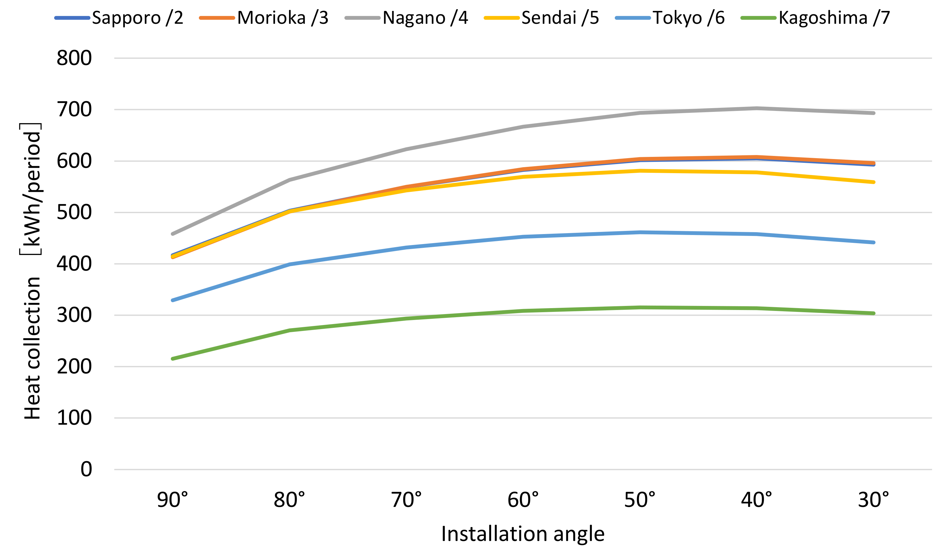
The study examined the optimal installation conditions for SAH. Panels can be installed not only on the wall but also at an angle. Figure 4 illustrates the calculated heat collection during the heating period according to the angle of the installation. As shown in Figure 5, the installation angle is 90° for vertical (wall installation) and 0° for horizontal, relative to the ground. The heat collection rate increases as the angle becomes slower. In each zone, the maximum heat collection angle is 40° to 50°, in which case the heat collection rate is 40% to 50% higher than that for wall installation. However, at less than 70°, the rate of increase in the heat collection rate decreases, and the rate of increase of the maximum heat collection rate from the heat collection rate at a 70° installation is approximately 10%. Conversely, a 30-degree angle resulted in a decrease in heat collection compared with a 40-degree angle.
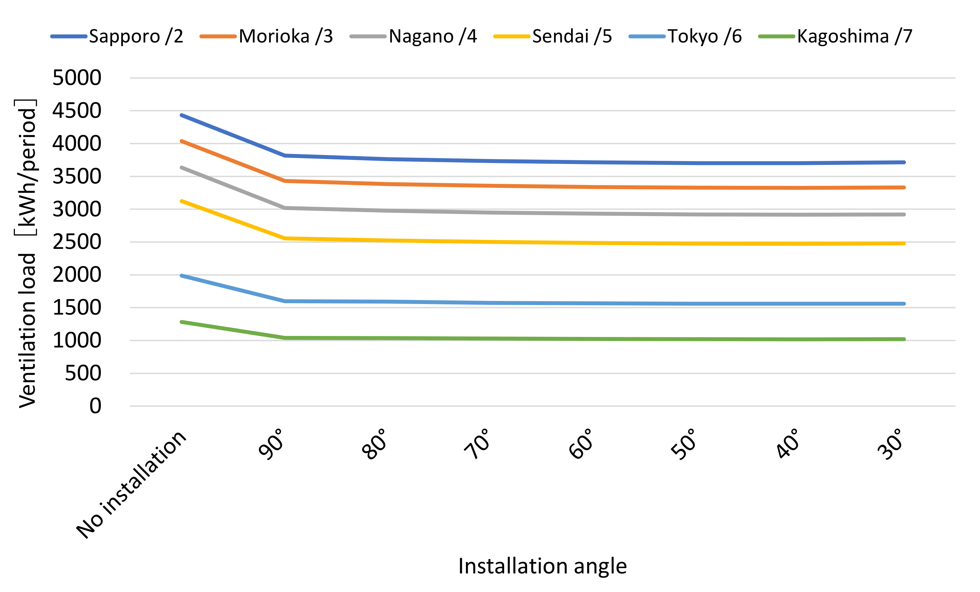
Figure 6 and Figure 7 depict the ventilation load by the angle of the PVSAH installation during the heating season and the percentage reduction in ventilation load, respectively. Installing the SAH on the wall (90°) reduces ventilation load by 15–20%. In this study, heat collection that exceeds the ventilation load did not lead to a reduction in ventilation load. Therefore, when mounted on a building, the increase in heat collection due to the installation angle exceeds the ventilation load and is passed on to the auxiliary heating effect. Even if the heat collection rate is increased by lowering the installation angle compared with that of the wall installation, the reduction rate is only 2–3% at maximum. Given the effects of snow accumulation in cold regions, strong winds such as typhoons in hot and humid regions, and obstruction caused by protrusion from buildings, a wall installation (90°) was considered, which is advantageous from a design standpoint. However, excess heat collection (overheating) by the SAH beyond the ventilation load contributes to energy savings as supplemental heating. Therefore, if conditions permit, an angled installation at no additional cost would be more desirable because it would increase energy efficiency.

3.2. Evaluation of Primary Energy Consumption by Ventilation System

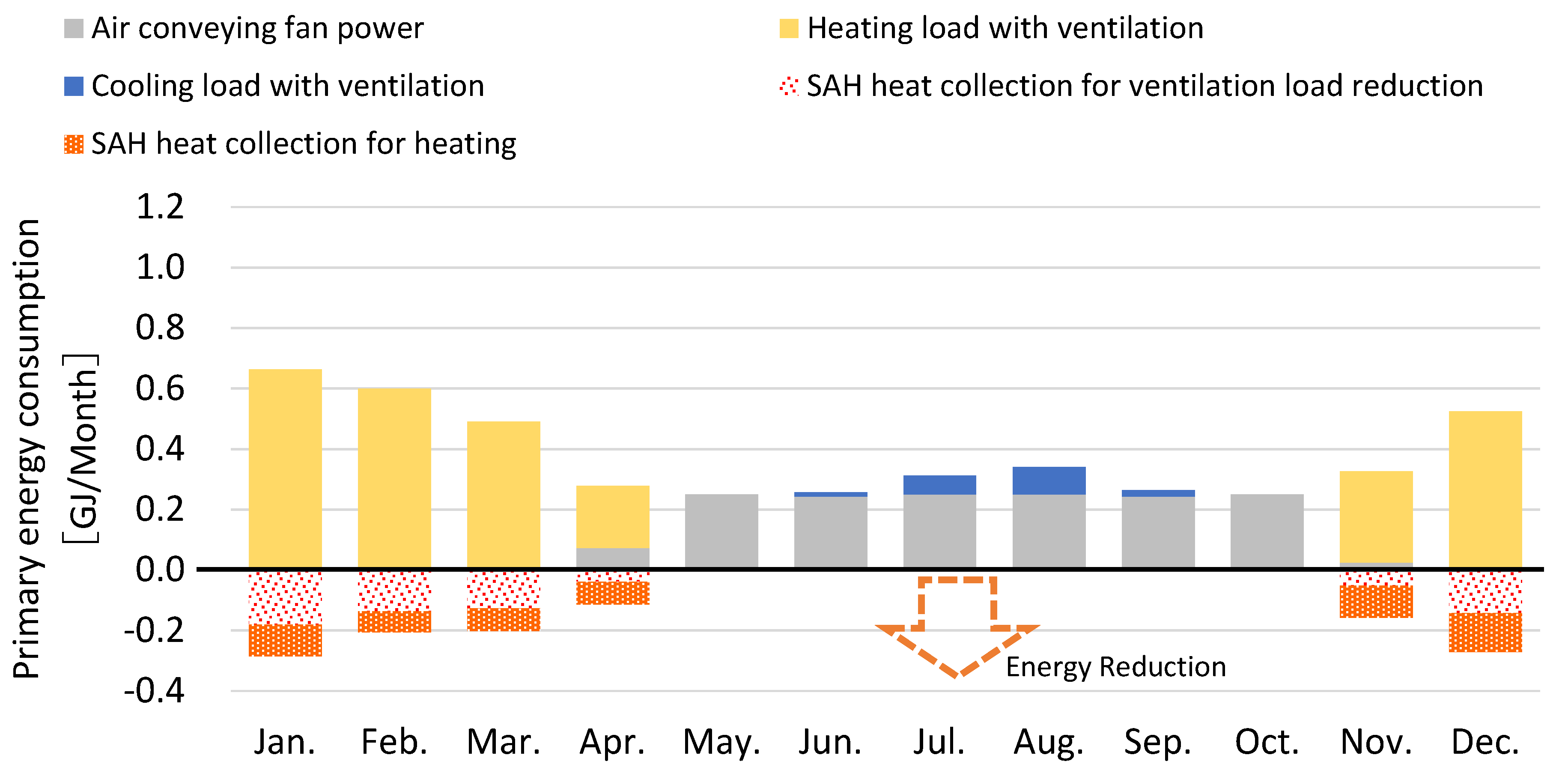
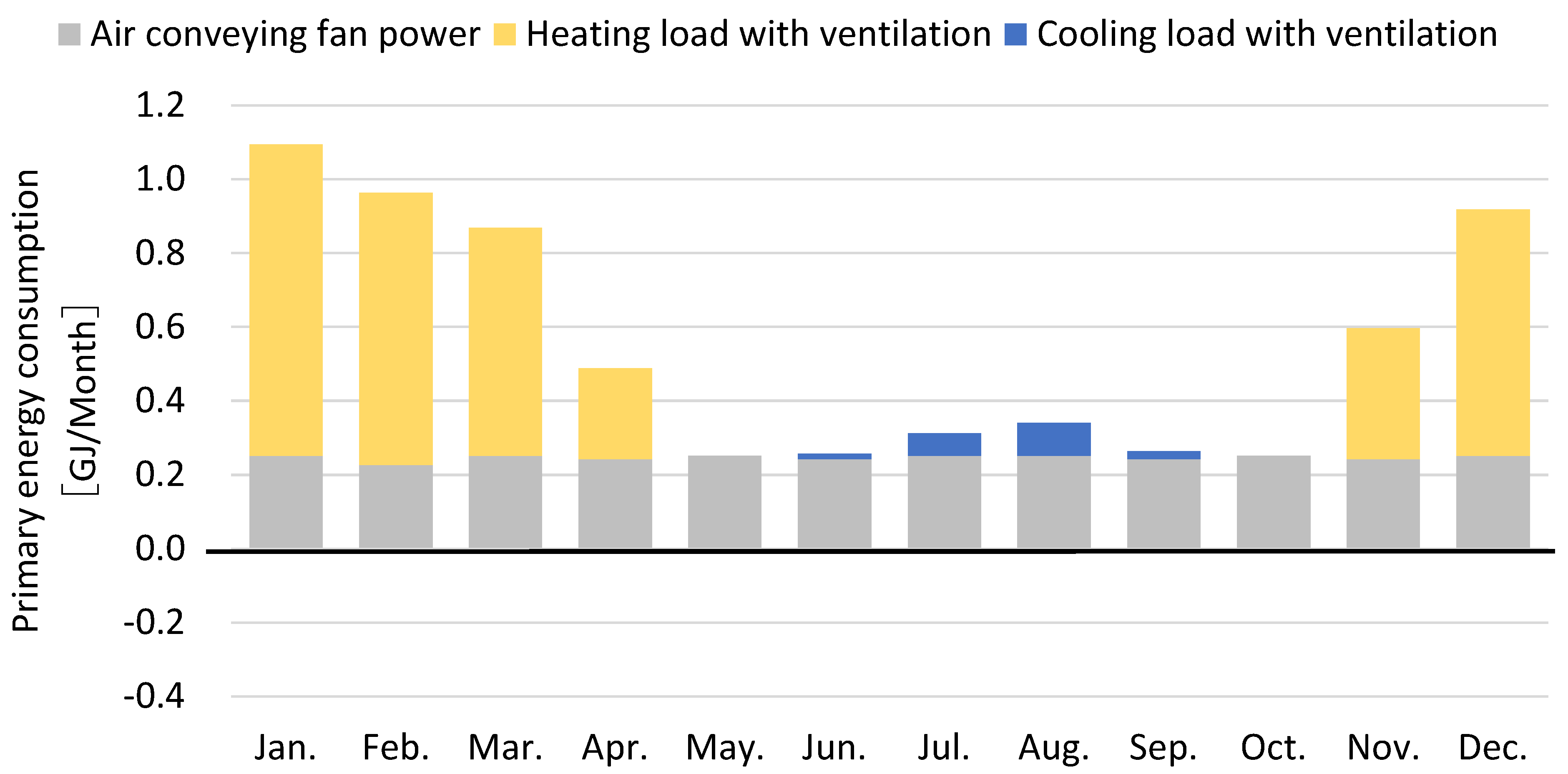
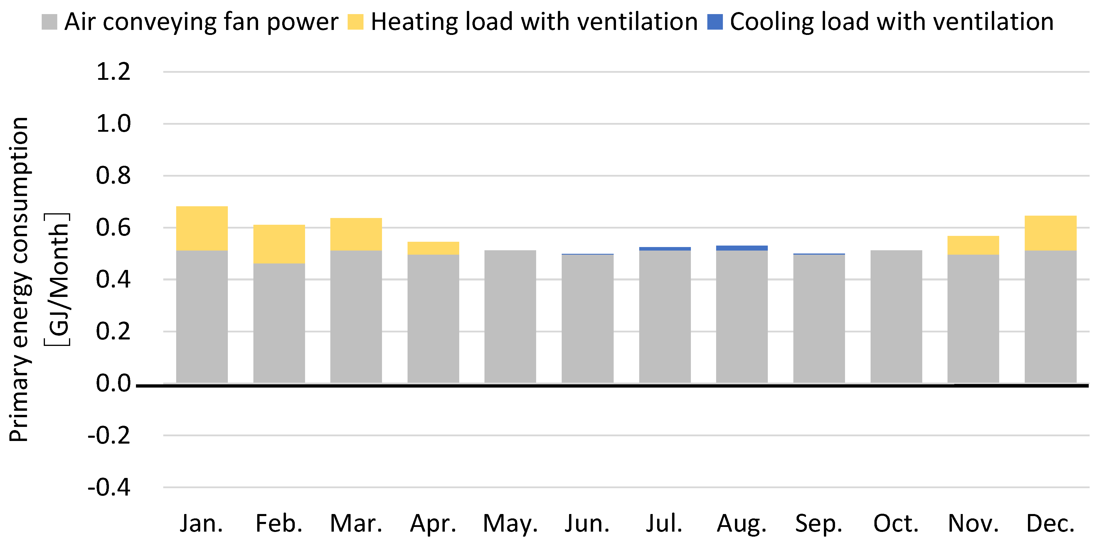
To understand the characteristics of each system, Figure 8, Figure 9 and Figure 10 illustrate the monthly primary energy consumption when heating and cooling with heat pumps are used in Tokyo (Zone 6). SAHs installation was studied with wall installation (90°). PVSAH does not generate air conveying fan power during the heating season, which results in significant energy savings. Heat collection by the SAH reduces ventilation load, and the amount beyond that contributes to energy savings in the form of an auxiliary heating effect. The negative values in Figure 8 represent the ventilation load and auxiliary heating effect reduced by the heat collection of the SAH. The auxiliary heating effect is only shown in the graph and is not included in the calculation of energy savings. The primary energy consumption of the PVSAH is 4.6 GJ/year, which is significantly lower than the 6.6 GJ/year of a typical MEV.
Conversely, HRV consumes air conveying fan power throughout the year, even during periods without the heating load, and consumes significantly more energy than the ventilation load. In addition, the ventilation load during summer cooling is relatively small compared with the reduced ventilation load in winter, and energy savings are limited. As a result, the annual primary energy consumption of the HRV was 6.8 GJ/year, which is 0.2 GJ/year more energy than that of the MEV, and the HRV consumed significantly more energy than the PVSAH.
The study then compared the primary energy consumption by zone for each ventilation system. Figure 11 and Figure 12 illustrate the case of heat pump heating and cooling and the case of gas heating, respectively. In the case of heat pump heating, PVSAH saves more energy than HRV in Zone 4 and the south. In Zones 2 and 3, even PVSAH without heat recovery can save significantly more energy than MEV can. In cold regions, HRV is more energy efficient than the PVSAH, but the PVSAH is also more energy efficient than the MEV. Given the effects of maintenance, defrosting, and differences in building airtightness, PVSAH also poses merit in being selected as an energy conservation measure. Comparing the energy conservation effect of HRVs with that of MEVs, HRVs present an advantage in the cold regions of Zones 2 to 5, but the opposite is true for Zones 6 and 7, in which energy consumption increases. In contrast, the energy-saving effect of PVSAH on MEV was stable at 25–30% regardless of region. The amount of heat recovered from HRV decreases in warmer regions, and the ratio of energy used by air conveying fan power increases, such that PVSAH with less air conveying fan power is advantageous.
Alternatively, in the case of gas heating + heat pump cooling, the ratio of air conveying fan power is lower due to the lower energy efficiency of the heating system. Therefore, HRV generally presents an advantage. In Zone 7, the PVSAH is more energy efficient than the HRV, but in the north of Zone 6, the HRV is more energy efficient. However, the PVSAH is 20–25% more energy efficient than the MEV, which makes the PVSAH an effective energy conservation option apart from the HRV. In addition, the value of using PVSAH is expected to increase in the future because its heating efficiency is likely to improve with the evolution of energy conservation technology and building renovation.
Against this background, PVSAH will have a high energy-saving effect in warm zones where heating energy efficiency is high and the energy-saving effect of HRV will be limited.

3.3. Comparison of CO2 Emission per System

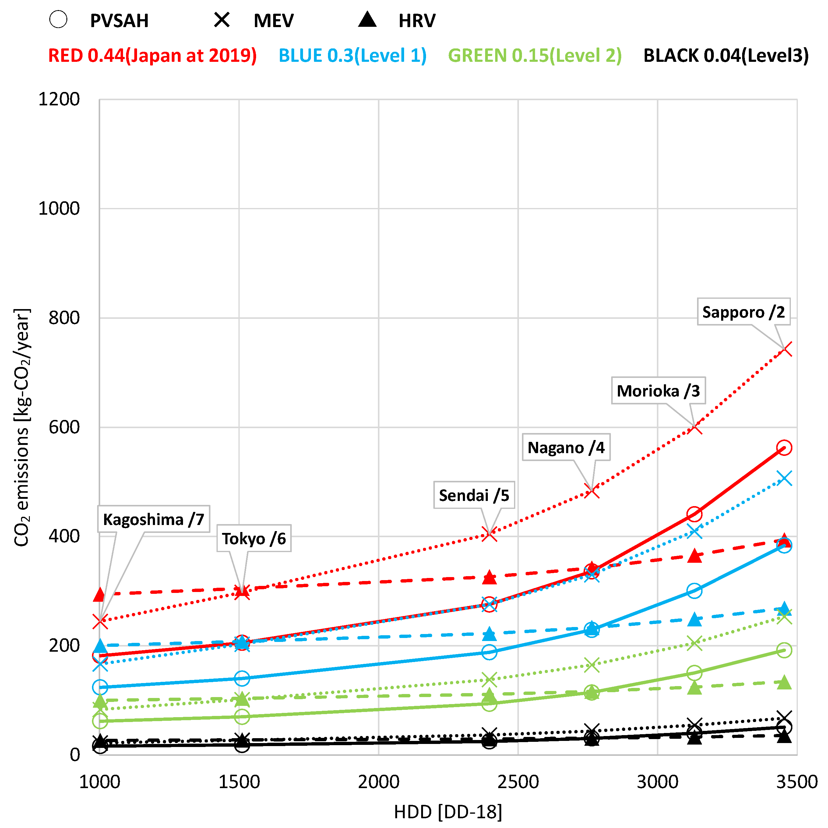
Figure 13 and Figure 14 illustrate the results of the comparison of the annual CO2 emissions of the ventilation systems for each zone. SAHs were studied with wall installation (90°) as well as primary energy consumption. Specifically, Figure 13 presents the calculation results for heat pump heating and cooling, and Figure 14 demonstrates those for gas heating + heat pump cooling. The study also focuses on the reduction of the CO2 emission factor and evaluates changes in this factor. The values in Table 4 were used to calculate CO2 emissions.
In the case of the gas heating and heat pump cooling systems, the study observed a small change in CO2 emissions despite the change in the CO2 emission factor of electricity because the gas combustion energy efficiency of heating remained the same. Therefore, HRV, which can reduce heating energy, poses a significant advantage.
In the case of heat pump heating and cooling, HRV can significantly reduce CO2 emissions at all emission factor levels in cold climates. However, in warmer climates, systems with less air conveying fan power are favorable, and the difference in CO2 emissions for the total ventilation load is reduced. At HDD 2750, PVSAH reverses with HRV, and CO2 emissions are lower. PVSAH presents the largest advantage in the south below HDD 2750. MEV reverses its advantage with HRV after HDD 1500. In warmer climates, HRV does not work to save CO2. In addition, the level of emission factors will increase with the increased prevalence of renewable energy sources, and CO2 emission factors will decrease with the goal of decarbonization. As the level of the emission factor increases, the difference in CO2 emissions between ventilation systems will decrease. A comparison of HRV and MEV at Level 3, which presents the lowest CO2 emission factor, illustrates a maximum of 32 kg/year in cold climates and only a small difference of 5 kg/year in warm climates. Since the difference among systems is very small, factors apart from energy conservation performance, such as initial and running costs, including maintenance and management costs, and the risk of failure, are also important for system selection. A simple system configuration with a low risk of failure and maintenance, such as PVSAH, is expected to be highly advantageous in the future.

4. Conclusions

As an energy-saving technology for ventilation, the evaluation considered not only ventilation load but also air conveying fan power. The study obtained the following findings by comparing the energy conservation performance of the proposed PVSAH with that of HRV and MEV:
(1)
The installation angle of the SAH used in the outdoor air intake area was examined. An angled installation increases heat collection compared with that of a wall installation (90°). For each zone, the maximum heat collection was achieved at installation angles of 40° to 50°. The effect of SAH installation at 90° is 15–20% but changing the angle of installation only improves reduction by a maximum of 2–3%. In addition, the installation of the system on a building at an angle requires consideration of the effects of snow accumulation in cold regions, the effects of typhoons and other strong winds in hot regions, and obstructions caused by the protrusion of the system from the building. Therefore, the study conducted a 90-degree installation on a wall. The results indicated that an angled installation is preferable if conditions permit because it is less expensive, reduces ventilation load by 2–3%, and provides an auxiliary heating effect.
(2)
The monthly primary energy consumption of each ventilation system was evaluated in Zone 6 (Tokyo) for heat pump heating and cooling. PVSAH exhibited the highest energy savings because it does not generate air transfer power during the heating season and because of the reduction in ventilation load due to SAH. HRV can reduce ventilation load, but it also generates large air conveying fan power throughout the year, even without heating load. The reduction in ventilation load was a trade-off, which resulted in an energy increase.
(3)
The primary energy consumption was evaluated by zone. In the case of heat pump heating with high heating efficiency, PVSAH was superior to HRV in Zone 5 and in the south and displayed the same energy-saving performance in Zone 4. In warmer zones (6–7), HRV was at a disadvantage compared with MEV, with HRV presenting an advantage in colder climates but a disadvantage in warmer climates. However, PVSAH can save more energy than MEV can, even in cold regions. Given the impact of maintenance, defrosting, and differences in building airtightness, selecting PVSAH as an energy conservation measure apart from HRV could lead to advantages. In the case of gas heating with low heating efficiency, PVSAH was equal to HRV in Zone 7, while HRV was advantageous in other zones. However, PVSAH saves 20–25% energy compared to MEV, which makes PVSAH an effective energy conservation option apart from HRV. In addition, the value of using PVSAH is expected to increase in the future due to the evolution of energy conservation technology and the possibility that heating efficiency will increase with the renovation of building facilities.
(4)
The CO2 emissions of different ventilation systems were compared. In the case of gas heating + heat pump cooling, the change is small, despite the change in the CO2 emission factor of electricity, because the gas combustion energy efficiency of the heating remains the same. Therefore, HRV is significantly more advantageous because heating energy can be significantly reduced. In the case of heat pump cooling and heating, however, HRV poses an advantage in cold climates but a disadvantage in warmer climates because the amount of air conveying fan power does not decrease. HDD 1500 and below: PVSAH > MEV > HRV; HDD 1500 to 2750: PVSAH > HRV > MEV; and HDD 2750 and above: HRV > PVSAH > MEV, in this order. In addition, as the CO2 emission factor decreases, the difference in CO2 emissions between systems decreases. If the difference in emissions becomes smaller, then considering the initial and running (including maintenance and upkeep) costs and the risk of failure of the system is crucial. A simple system configuration with low risks of failure and maintenance, such as PVSAH, may prove advantageous in the future.
In this paper, we propose PVSAH as a simple system that is less burdensome to maintain and manage, in contrast to HRV, which is high performance but poses issues with maintenance, management, and performance demonstration. It is not only an energy-saving system but also a simple system that considers the initial, running, and maintenance costs. The study found that the system can be fully utilized according to regional characteristics, characteristics of the residents, energy efficiency, and power supply configuration.

Author Contributions

Conceptualization, J.M. and K.K.; validation, all authors; writing—original draft preparation, J.M. and K.K.; writing—review and editing, all authors; All authors have read and agreed to the published version of the manuscript.

Funding

This research received no external funding.

Data Availability Statement

The data are contained within this study.

Conflicts of Interest

The authors declare no conflict of interest.

Nomenclature

Q p SAH air flow ratem3/h
Q c Heat collection capacityW
Q Air flow ratem3/h
Q u Ventilation loadW
M ¯ Equivalent heat capacityJ/K
M A Heat capacity of air in panelJ/K
M B Part of the heat capacity of surrounding componentsJ/K
U U-value W/(m2K)
A Aream2
T Temperature°C
J R Amount of solar radiation transmitted into the panelW/m2
t Times
η Heat collection efficiency of SAH-
η t Heat exchange efficiency-
E Fan powerWh
F Specific fan powerWh/m3
f front of panel
b back of panel
p hollow layer in the device
o outside air
i indoor air

References

  1. Laverge, J.; Janssens, A. Heat recovery ventilation operation traded off against natural and simple exhaust ventilation in Europe by primary energy factor, carbon dioxide emission, household consumer price and exergy. Energy Build. 2012, 50, 315–323. [Google Scholar] [CrossRef]
  2. Dodooa, A.; Gustavsson, L.; Sathrea, R. Primary energy implications of ventilation heat recovery in residential buildings. Energy Build. 2011, 43, 1566–1572. [Google Scholar] [CrossRef]
  3. Wu, W.; Fang, Z.; Ji, W.; Wang, H. Optimal operation condition division with profit and losses analysis of energy recovery ventilator. Energy Build. 2016, 124, 203–209. [Google Scholar] [CrossRef]
  4. El Fouiha, Y.; Stabat, P.; Rivièreb, P.; Hoang, P.; Archambault, V. Adequacy of air-to-air heat recovery ventilation system applied in low energy buildings. Energy Build. 2012, 54, 29–39. [Google Scholar] [CrossRef]
  5. Zhang, J.; Fung, A. Experimental study and analysis of an energy recovery ventilator and the impacts of defrost cycle. Energy Build. 2015, 87, 265–271. [Google Scholar] [CrossRef]
  6. Zhang, J.; Fung, A. Experimental and numerical investigation of the thermal impact of defrost cycle of residential heat and energy recovery ventilators. Energy Build. 2015, 97, 129–136. [Google Scholar] [CrossRef]
  7. Fisk, W.; Turiel, I. Residential Air-to-Air Heat Exchangers: Performance, Energy Savings, and Economics. Energy Build. 1983, 5, 197–211. [Google Scholar] [CrossRef] [Green Version]
  8. Dorer, V.; Breer, D. Residential mechanical ventilation systems: Performance criteria and evaluations. Energy Build. 1998, 27, 247–255. [Google Scholar] [CrossRef]
  9. Choi, Y.; Song, D.; Seo, D.; Kim, J. Analysis of the variable heat exchange efficiency of heat recovery ventilators and the associated heating energy demand. Energy Build. 2018, 172, 152–158. [Google Scholar] [CrossRef]
  10. Maier, T.; Krzaczek, M.; Tejchman, J. Comparison of physical performances of the ventilation systems in low-energy residential houses. Energy Build. 2009, 41, 337–353. [Google Scholar] [CrossRef]
  11. Laverge, J.; Van Den Bossche, N.; Heijmans, N.; Janssens, A. Energy saving potential and repercussions on indoor air quality of demand controlled residential ventilation strategies. Energy Build. 2011, 46, 1497–1503. [Google Scholar] [CrossRef] [Green Version]
  12. Cho, W.; Song, D.; Hwang, S.; Yun, S. Energy-efficient ventilation with air-cleaning mode and demand control in a multi-residential building. Energy Build. 2015, 90, 6–14. [Google Scholar] [CrossRef]
  13. Fisk, W.; De Almeida, A. Sensor-based demand-controlled ventilation: A review. Energy Build. 1998, 29, 35–45. [Google Scholar] [CrossRef] [Green Version]
  14. Guyot, G.; Sherman, M.; Walker, I. Smart ventilation energy and indoor air quality performance in residential buildings: A review. Energy Build. 2018, 165, 416–430. [Google Scholar] [CrossRef] [Green Version]
  15. Southall, R.G. An assessment of the potential of supply-side ventilation demand control to regulate natural ventilation flow patterns and reduce domestic space heating consumption. Energy Build. 2018, 168, 201–214. [Google Scholar] [CrossRef]
  16. Turner, W.J.N.; Walker, I.S. Using a ventilation controller to optimise residential passive ventilation for energy and indoor air quality. Build. Environ. 2013, 70, 20–30. [Google Scholar] [CrossRef]
  17. Jreijiry, D.; Husaunndee, A.; Inard, C. Numerical study of a hybrid ventilation system for single family houses. Sol. Energy 2007, 81, 227–239. [Google Scholar] [CrossRef]
  18. Matsunaga, J.; Kikuta, K.; Hirakawa, H.; Mizuno, K.; Tajima, M.; Hayashi, M.; Fukushima, A. An Assessment of Heating Load Reduction by Solar Air Heater in a Residential Passive Ventilation System. Energies 2021, 14, 7651. [Google Scholar] [CrossRef]
  19. Building Research Institute. Technical Information on Energy Consumption Performance of Buildings. (In Japanese). Available online: https://www.kenken.go.jp/becc/index.html (accessed on 28 June 2023).
  20. Yoshino, H.; Akabayashi, S.; Kato, S.; Ikeda, K.; Sawachi, T.; Adachi, M. Survey on Minimum Ventilation Rate for Residential Buildings on Advanced Countries. AIJ J. Technol. Des. 2004, 19, 189–192. (In Japanese) [Google Scholar] [CrossRef]
  21. Meteorological Data System Co., Ltd. Expanded AMeDAS Weather Data; Meteorological Data System Co., Ltd.: Kagoshima, Japan, 2010; (In Japanese). Available online: https://www.metds.co.jp/documents/ea/ (accessed on 28 June 2023).
  22. The Society of Heating, Air-Conditioning and Sanitary Engineers of Japan. SHASE-S112-2019, Simplified Calculation Methods of Cooling and Heating Loads; The Society of Heating, Air-Conditioning and Sanitary Engineers of Japan: Tokyo, Japan, 2019. (In Japanese) [Google Scholar]
  23. National Institute for Land and Infrastructure Management; MLIT; Building Research Institute. Incorporated Administrative Agency: Design Guidelines for Low Energy Housing with Validated Effectiveness: Mild Climate Region Edition; IBEC: Tokyo, Japan, 2015. (In Japanese) [Google Scholar]
  24. International Energy Agency. Annual GHG Emission Factors for World Countries from Electricity and Heat Generation, Data and Statistics 2019; International Energy Agency: Paris, France, 2019. [Google Scholar]
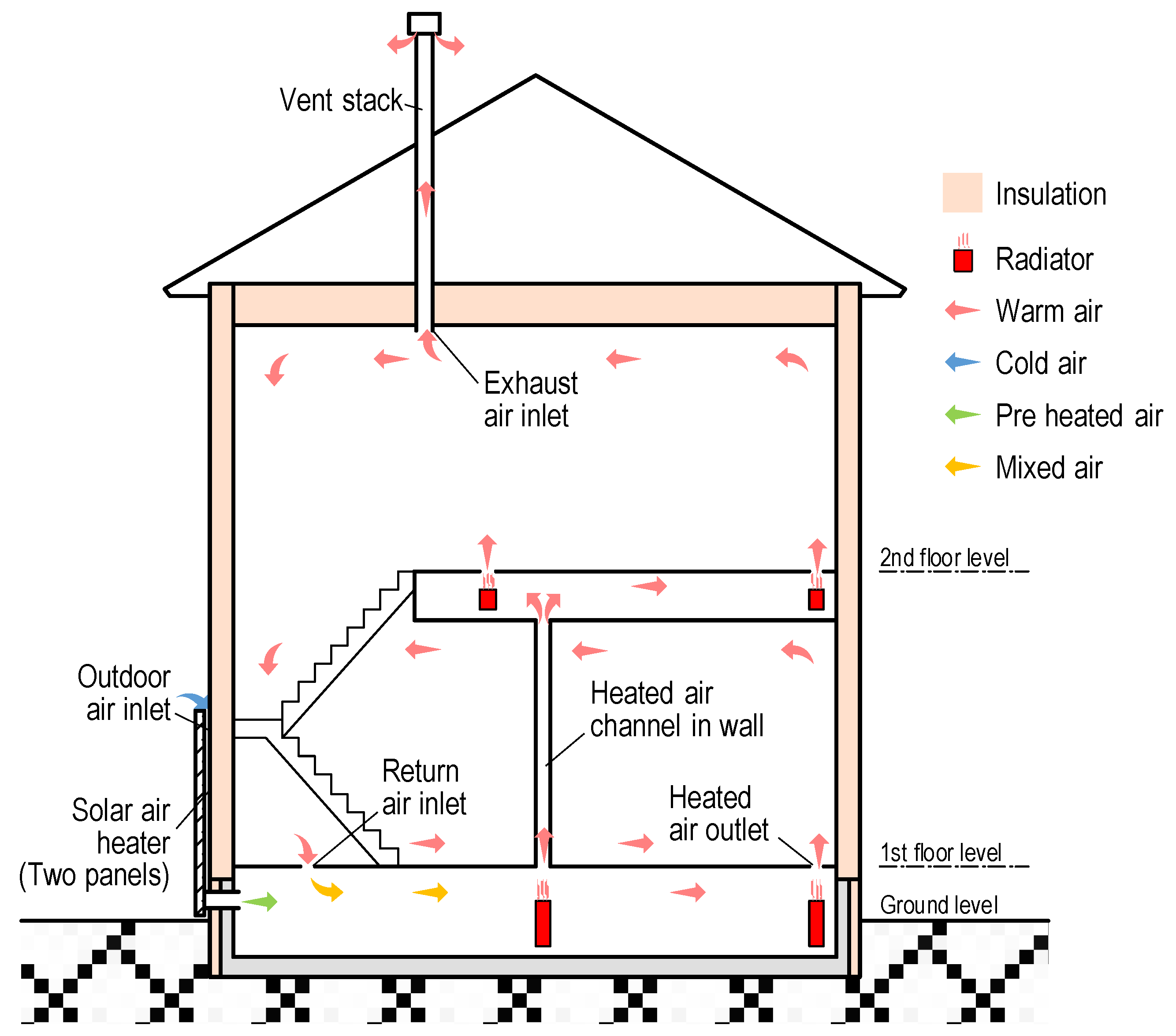
Figure 1. Overview of the passive ventilation system with a solar air heater (PVSAH) [18].
Energies 16 05535 g001
Figure 2. Overview of the solar air heater (SAH) [18].
Energies 16 05535 g002
Figure 3. Overview of the system diagram. (a) PVSAH, (b) MEV, and (c) HRV.
Energies 16 05535 g003
Figure 4. Comparison of heat collection by the angle of SAH installation by zone.
Energies 16 05535 g004
Figure 5. Installation angle of SAH.
Energies 16 05535 g005
Figure 6. Ventilation load during the heating period by the angle of SAH installation by zone.
Energies 16 05535 g006
Figure 7. Reduction of ventilation load during the heating period by SAH by zone.
Energies 16 05535 g007
Figure 8. Monthly primary energy consumption of PVSAH.
Energies 16 05535 g008
Figure 9. Monthly primary energy consumption of MEV.
Energies 16 05535 g009
Figure 10. Monthly primary energy consumption of HRV.
Energies 16 05535 g010
Figure 11. Annual primary energy consumption of a heat pump.
Energies 16 05535 g011
Figure 12. Annual primary energy consumption of a gas boiler.
Energies 16 05535 g012
Figure 13. Annual CO2 emissions of a heat pump.
Energies 16 05535 g013
Figure 14. Annual CO2 emissions of a gas boiler.
Energies 16 05535 g014
Table 1. Comparison of ventilation systems.
SystemSpecific Fan PowerAir Change per HourHeat Exchange EfficiencyHeat Collection Efficiency of SAH
Wh/m3h−1--
Mechanical Exhaust Ventilation System0.240.5--
Passive Ventilation System with a Solar Air HeaterHeating period0.000.5-0.6 1
(Rated efficiencies)
Non-heating
period
0.240.5--
Heat Recovery Ventilation System0.490.50.8-
1 The calculation uses Equation (4). This number is variable.
Table 2. Selected zones and their regional characteristics.
CityZoneNorth LatitudeHeating
Degree-Day
(HDD18-18)
Maximum
Air Temperature (°C)
Annual Snowfall (cm)Annual Amount of Solar Radiation (MJ/m2)Heating PeriodHeating APFGas
Boiler Efficiency
East LongitudeMinimum
Air Temperature (°C)
Cooling PeriodCooling APF
Sapporo243°03′51″4499~35003247944369/26~6/43.20.87
141°20′49″−11.47/15~8/316.6
Morioka339°42′13″3499~300031.920945389/30~5/313.8
141°09′09″−12.27/10~8/316.6
Nagano436°39′05″2999~250035.7163535410/1~5/304.6
138°10′52″−8.27/10~8/316.4
Sendai538°16′08″2499~200035.459449510/10~5/155.1
140°52′19″−4.27/6~8/315.7
Tokyo635°41′22″1999~150035.28471311/4~4/215.6
139°41′30″−0.55/30~9/236.2
Kagoshima731°33′37″1499~50034.62522311/26~3/275.7
130°33′29″−0.35/15~10/136.3
Table 3. Conversion factor per unit of primary energy.
Energy TypeConversion Factor per UnitCalorific Value per Unit
Electricity9.76 MJ/kWh1.000 kWh/kWh
Gas45.00 MJ/m312.083 kWh/m3
Table 4. CO2 emission factor.
LevelJapan in 2019Level 1Level 2Level 3
Electricity CO2 emission factor
[kg-CO2/kWh]
0.440.30.150.04
Gas CO2 emission factor
[kg-CO2/m3]
2.21
Disclaimer/Publisher’s Note: The statements, opinions and data contained in all publications are solely those of the individual author(s) and contributor(s) and not of MDPI and/or the editor(s). MDPI and/or the editor(s) disclaim responsibility for any injury to people or property resulting from any ideas, methods, instructions or products referred to in the content.