
Overview of Various Voltage Control Technologies for Wind Turbines and AC/DC Connection Systems


Abstract
1. Introduction
2. Various Voltage Control Methods
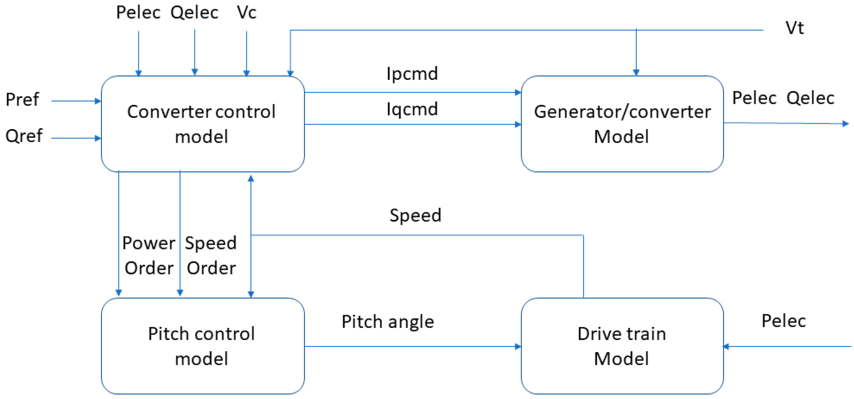
2.1. Wind Farm Control
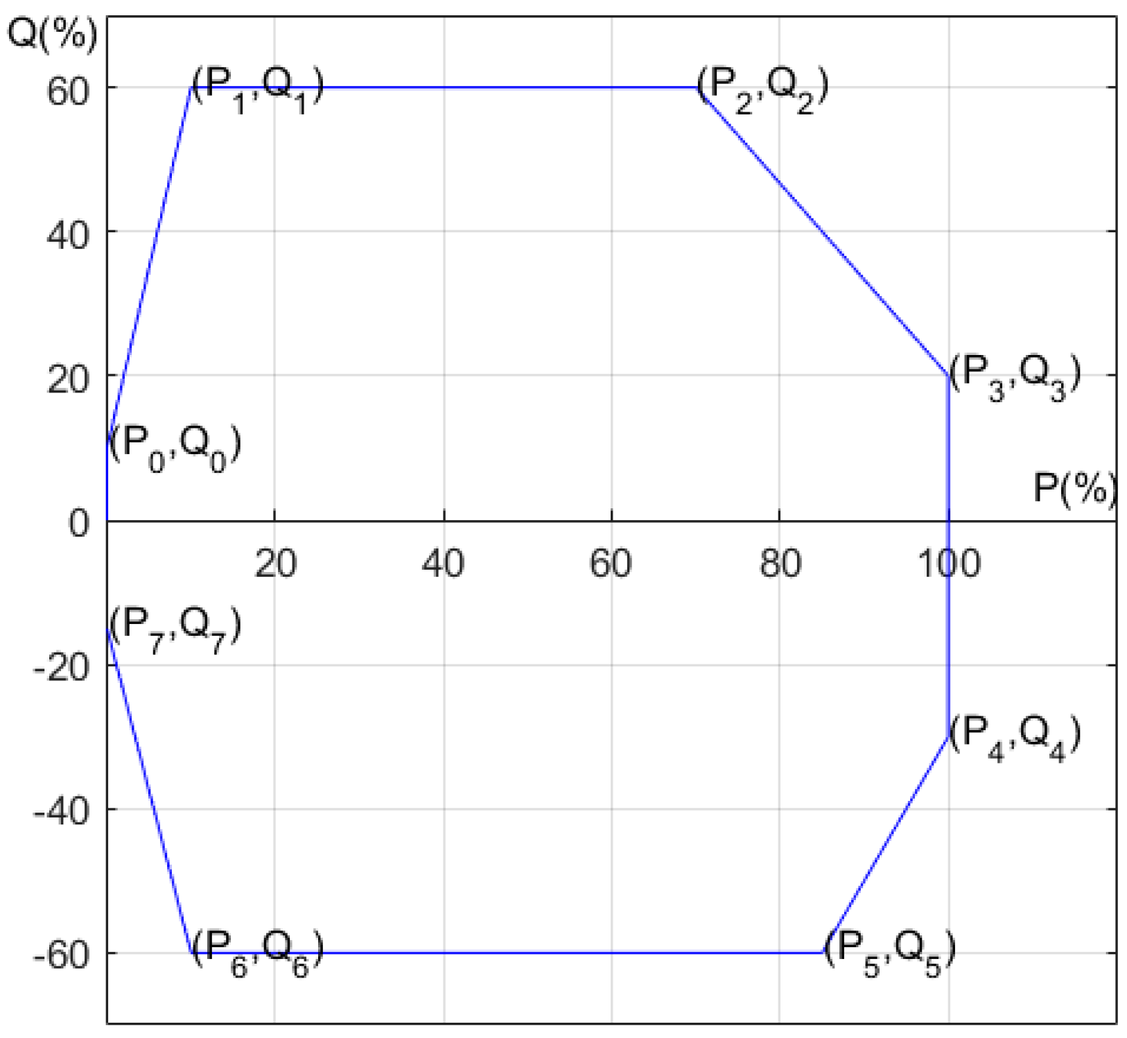
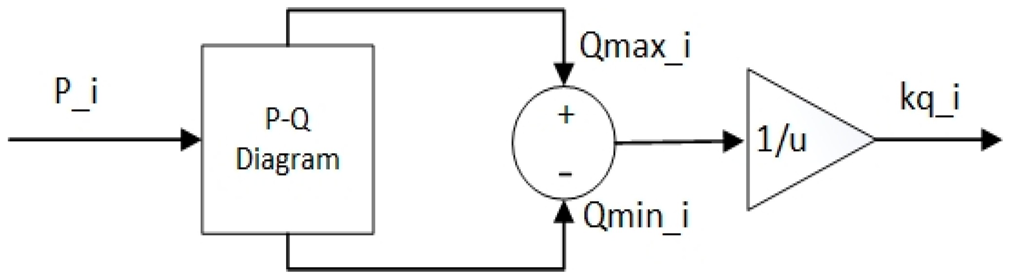
2.1.1. PQ Diagram
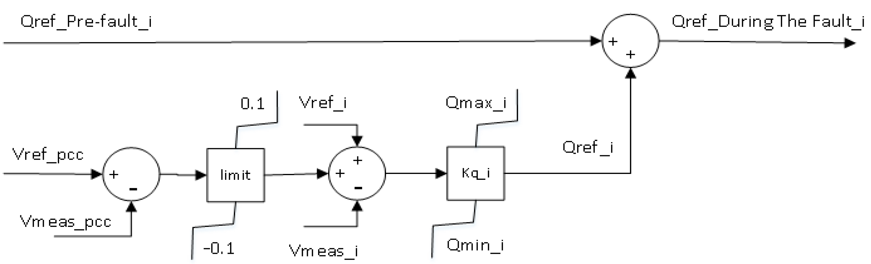
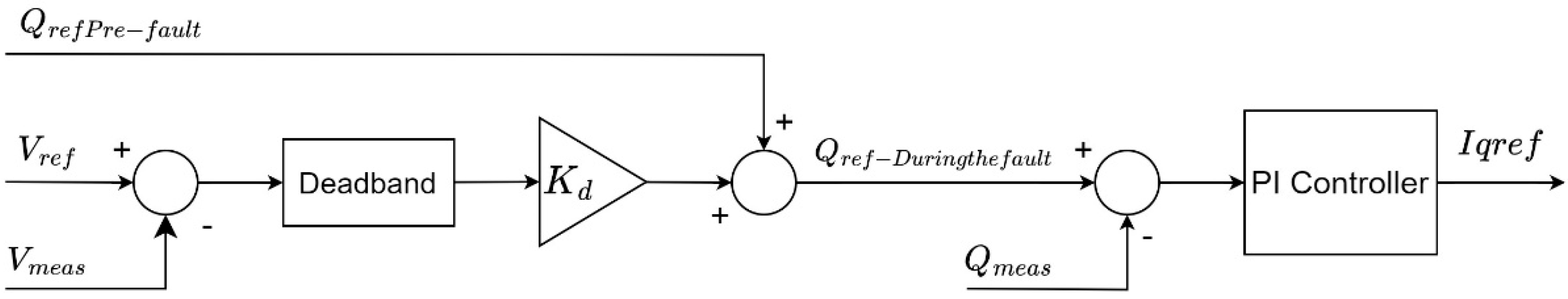
2.1.2. QV Control
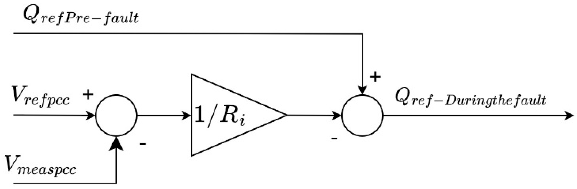
2.1.3. Voltage Droop Control
2.2. VSC-HVDC Control
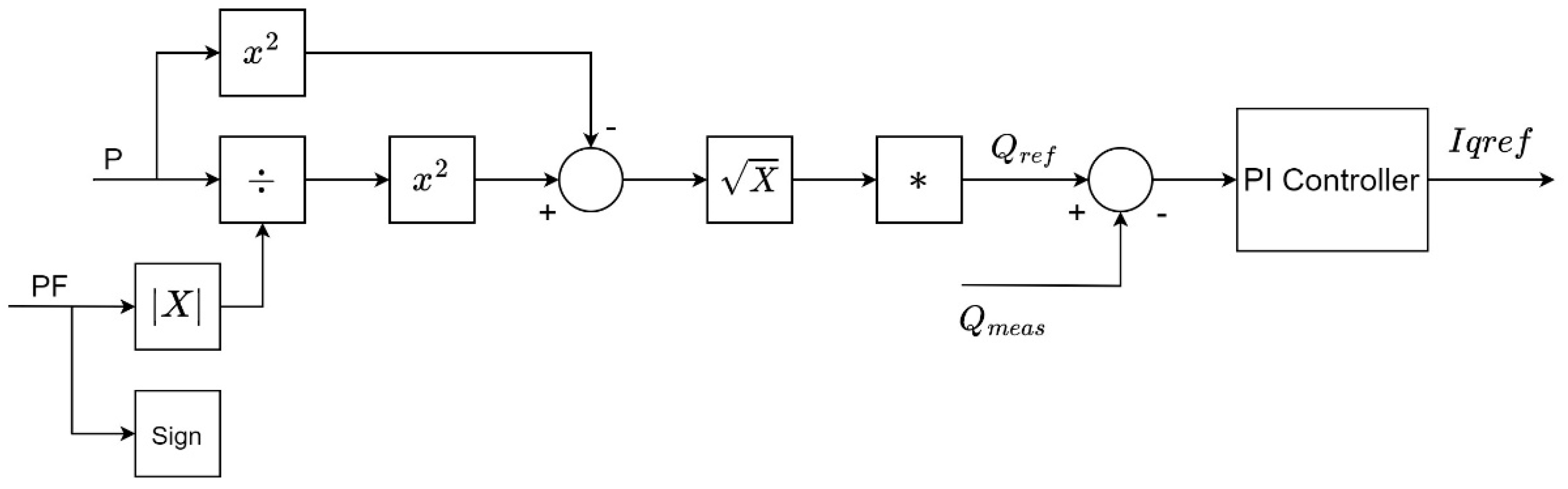
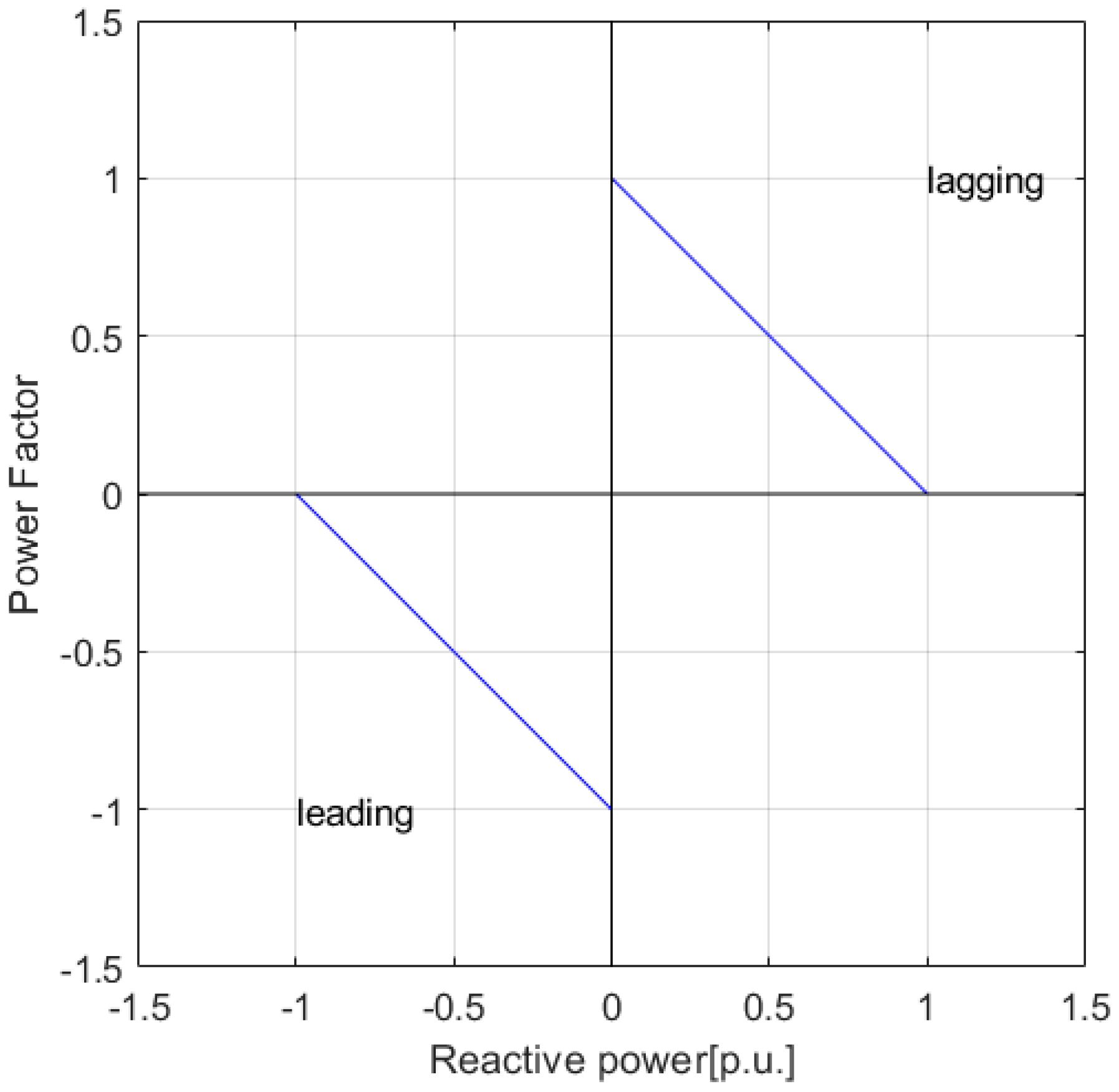
2.2.1. Power Factor Control
2.2.2. -Q Droop Control
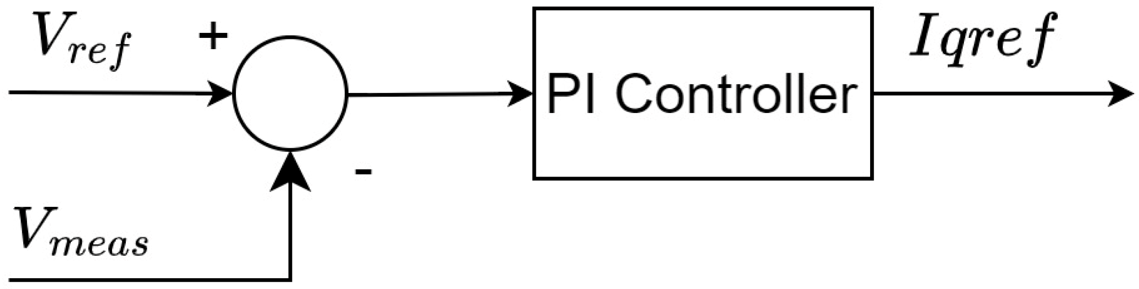
2.2.3. Voltage Control
3. Results and Discussions
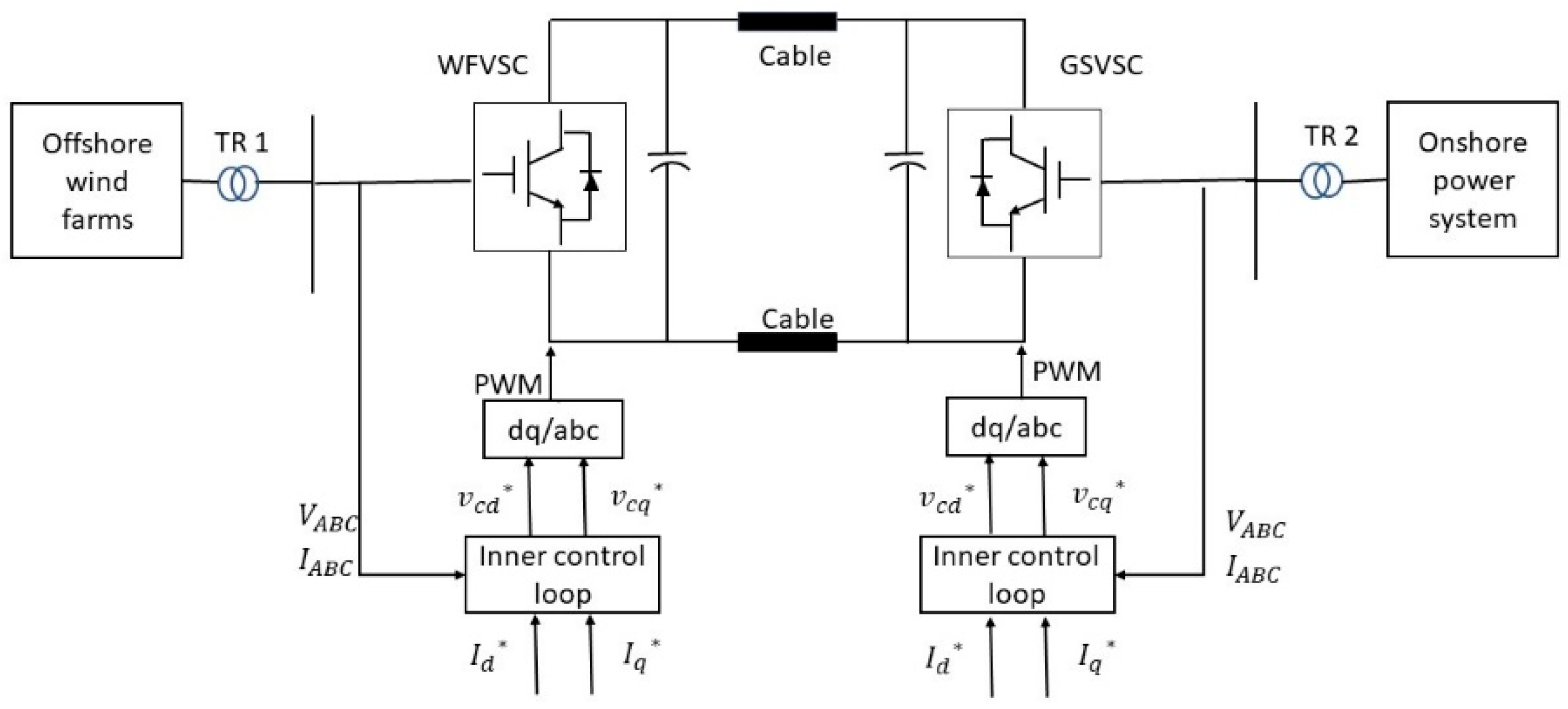
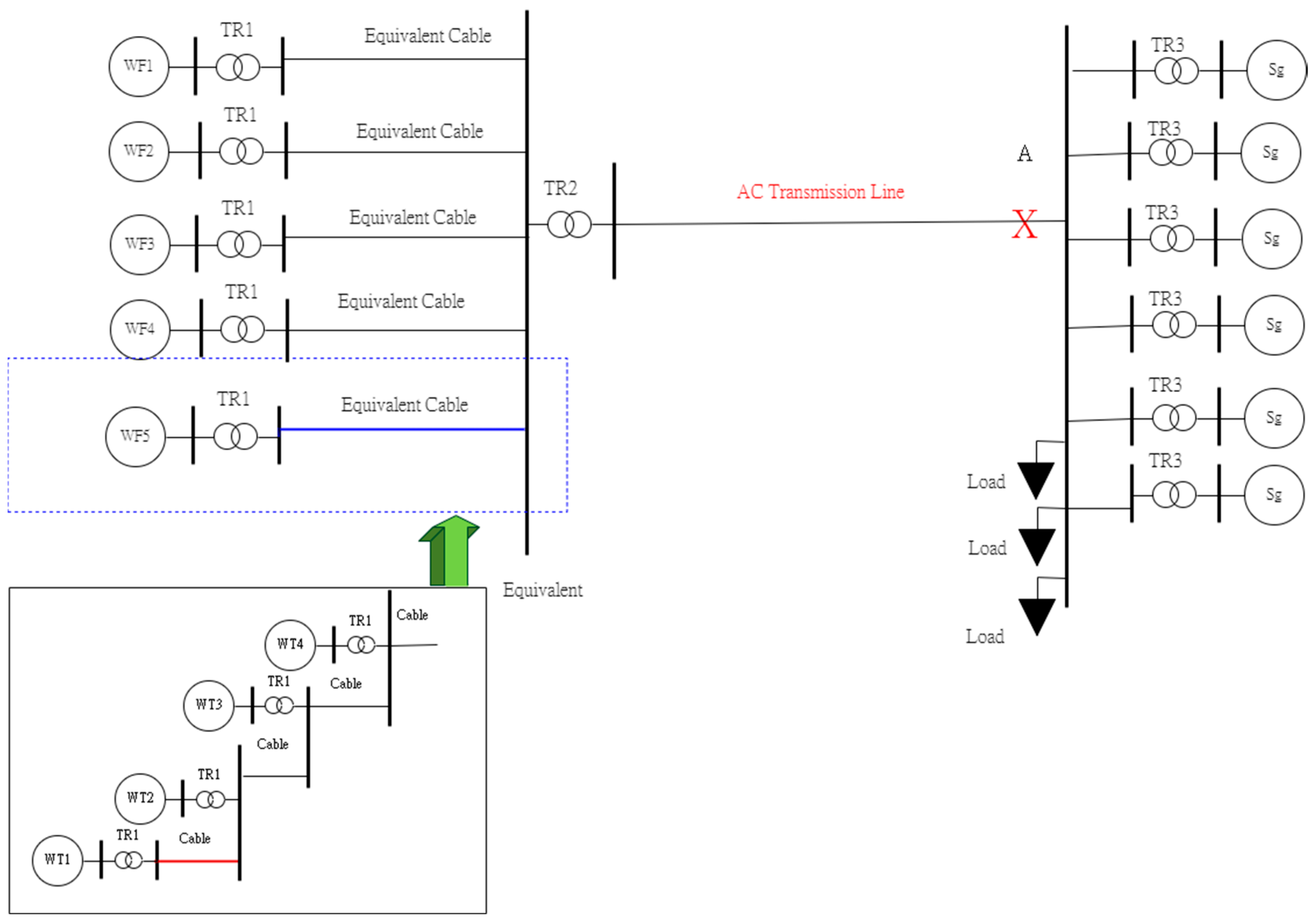
3.1. Simulation Topology of the Used AC System and HVDC System
3.2. A Reactive Power Load Is Added to the System with an AC Transmission System


3.3. A Reactive Power Load Is Added to the System with a VSC-HVDC Transmission System


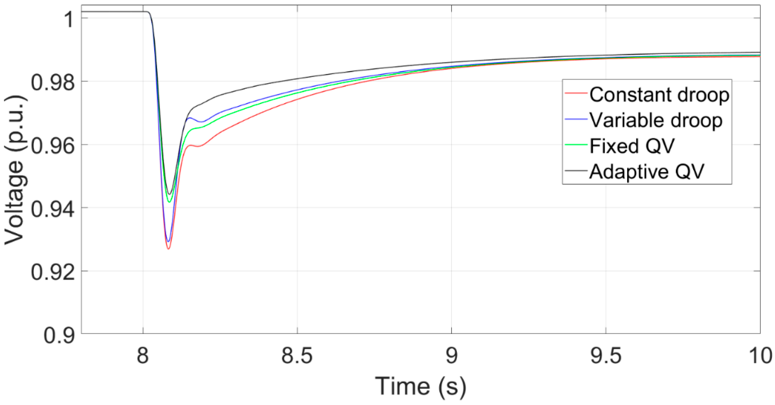
3.4. Three-Phase Short Circuit Fault at the System with an AC Transmission System


3.5. Three-Phase Short Circuit Fault at the System with a VSC-HVDC Transmission System
3.6. Comparison of an Increase of Reactive Power Load at Both Systems with Different Transmission Types


3.7. Comparison of Three-Phase Short Circuit Fault at Both Transmission Systems


3.8. Comparison of Tripping of Synchronous Generators at Both Transmission Systems
4. Conclusions
Author Contributions
Funding
Conflicts of Interest
References
- Wu, Y.-K.; Chang, S.-M.; Mandal, P. Grid-connected wind power plants: A survey on the integration requirements in modern grid codes. IEEE Trans. Ind. Appl. 2019, 55, 5584–5593. [Google Scholar] [CrossRef]
- Ellis, A.; Nelson, R.; Von Engeln, E.; MacDowell, J.; Casey, L.; Seymour, E.; Peter, W.; Williams, J.R.; Walling, R.; Barker, C.; et al. Review of existing reactive power requirements for variable generation. In Proceedings of the 2012 IEEE Power and Energy Society General Meeting, San Diego, CA, USA, 22–26 July 2012; pp. 1–7. [Google Scholar] [CrossRef]
- Martin, J.A.; Hiskens, I.A. Reactive power limitation due to wind-farm collector networks. In Proceedings of the 2015 IEEE Eindhoven PowerTech 2015, Eindhoven, The Netherlands, 29 June–2 July 2015; pp. 1–6. [Google Scholar] [CrossRef]
- Sharma, R. Electrical Structure of Future Off-Shore Wind Power Plant with a High Voltage Direct Current Power Transmission; Technical University of Denmark: Kongens Lyngby, Denmark, 2012. [Google Scholar]
- Silva, B.; Moreira, C.L.; Seca, L.; Phulpin, Y.; Lopes, J.A.P. Provision of Inertial and Primary Frequency Control Services Using Offshore Multiterminal HVDC Networks. IEEE Trans. Sustain. Energy 2012, 3, 800–808. [Google Scholar] [CrossRef]
- Nawir, M.; Adeuyi, O.; Wu, G.; Liang, J. Voltage stability analysis and control of wind farms connected to weak grids. In Proceedings of the 13th IET International Conference on AC and DC Power Transmission (ACDC 2017), Manchester, UK, 14–16 February 2017. [Google Scholar] [CrossRef]
- Schmall, J.; Huang, S.-H.; Li, Y.; Billo, J.; Conto, J.; Zhang, Y. Voltage stability of large-scale wind plants integrated in weak networks: An ERCOT case study. In Proceedings of the 2015 IEEE Power & Energy Society General Meeting, Denver, CO, USA, 26–30 July 2015; pp. 1–5. [Google Scholar]
- Huang, S.-H.; Schmall, J.; Conto, J.; Adams, J.; Zhang, Y.; Carter, C. Voltage control challenges on weak grids with high penetration of wind generation: ERCOT experience. In Proceedings of the 2012 IEEE Power and Energy Society General Meeting, San Diego, CA, USA, 22–26 July 2012; pp. 1–7. [Google Scholar] [CrossRef]
- Martínez, J.; Kjær, P.C.; Rodriguez, P.; Teodorescu, R. Design and Analysis of a Slope Voltage Control for a DFIG Wind Power Plant. IEEE Trans. Energy Convers. 2011, 27, 11–20. [Google Scholar] [CrossRef]
- Li, Q.; Zhang, Y.; Ji, T.; Lin, X.; Cai, Z. Volt/Var Control for Power Grids with Connections of Large-Scale Wind Farms: A Review. IEEE Access 2018, 6, 26675–26692. [Google Scholar] [CrossRef]
- Kim, J.; Seok, J.-K.; Muljadi, E.; Kang, Y.C. Adaptive Q–V Scheme for the Voltage Control of a DFIG-Based Wind Power Plant. IEEE Trans. Power Electron. 2015, 31, 3586–3599. [Google Scholar] [CrossRef]
- Li, Y.; Xu, Z.; Zhang, J.; Meng, K. Variable Droop Voltage Control for Wind Farm. IEEE Trans. Sustain. Energy 2017, 9, 491–493. [Google Scholar] [CrossRef]
- Liu, B.; Zhang, X.; Kong, D.; Liu, X.; Chang, X. Research on Reactive Power and Voltage Coordination Control Strategy for Multi-wind Farm Connecting to Power Grid. In Proceedings of the 2019 IEEE Innovative Smart Grid Technologies-Asia (ISGT Asia), Chengdu, China, 21–24 May 2019; pp. 1633–1637. [Google Scholar] [CrossRef]
- Basu, M.; Kim, J.; Nelms, R.M.; Muljadi, E. Coordination of Utility-scale PV Plant and Wind Power Plant in In-ter-area-Oscillation Damping. In Proceedings of the IEEE Transactions on Industry Applications 2023, Nashville, TN, USA, 29 October–2 November 2023; pp. 1–9. [Google Scholar]
- Jia, K.; Dong, X.; Wen, Z.; Wu, W.; Bi, T. Harmonic Injection Based Fault Ride-through Control of MMC-HVDC Connected Offshore Wind Farms. IEEE Trans. Sustain. Energy 2023, 1–11. [Google Scholar] [CrossRef]
- Dai, J.; Wan, L.; Chang, P.; Liu, L.; Zhou, X. Reactive Voltage Control Strategy for PMSG-Based Wind Farm Considering Reactive Power Adequacy and Terminal Voltage Balance. Electronics 2022, 11, 1766. [Google Scholar] [CrossRef]
- Tan, H.; Li, H.; Yao, R.; Zhou, Z.; Liu, R.; Wang, X.; Zheng, J. Reactive-voltage coordinated control of offshore wind farm considering multiple optimization objectives. Int. J. Electr. Power Energy Syst. 2021, 136, 107602. [Google Scholar] [CrossRef]
- Liu, W.; Liu, Y.; Wu, L. Model Predictive Control Based Voltage Regulation Strategy Using Wind Farm as Black-Start Source. IEEE Trans. Sustain. Energy 2023, 14, 1122–1134. [Google Scholar] [CrossRef]
- Mahish, P.; Mishra, S. Synchrophasor Data Based Q-V Droop Control of Wind Farm Integrated Power Systems. IEEE Trans. Power Syst. 2022, 38, 358–370. [Google Scholar] [CrossRef]
- Huang, S.; Wu, Q.; Guo, Y.; Chen, X.; Zhou, B.; Li, C. Distributed Voltage Control Based on ADMM for Large-Scale Wind Farm Cluster Connected to VSC-HVDC. IEEE Trans. Sustain. Energy 2019, 11, 584–594. [Google Scholar] [CrossRef]
- Han, C.; Huang, A.Q.; Baran, M.E.; Bhattacharya, S.; Litzenberger, W.; Anderson, L.; Johnson, A.L.; Edris, A.-A. STATCOM impact study on the integration of a large wind farm into a weak loop power system. IEEE Trans. Energy Convers. 2008, 23, 226–233. [Google Scholar]
- Mi, Z.; Tian, H.; Yu, Y.; Su, X.; Fan, X.; Feng, J. Study on voltage stability of power grid with large scale wind farm inter-connected. In Proceedings of the 2009 International Conference on Sustainable Power Generation and Supply, Nanjing, China, 6–7 April 2009; pp. 1–6. [Google Scholar]
- Ding, R.; Meng, C.; Qiao, Y. The coordinating control of voltage and reactive power between SVC and DFIG after LVRT. In Proceedings of the 2015 IEEE Eindhoven PowerTech 2015, Eindhoven, The Netherlands, 29 June–2 July 2015; pp. 1–5. [Google Scholar] [CrossRef]
- Latorre, H.F.; Ghandhari, M. Improvement of voltage stability by using VSC-HVdc. In Proceedings of the 2009 Transmission & Distribution Conference & Exposition: Asia and Pacific, Seoul, Republic of Korea, 26–30 October 2009; pp. 1–4. [Google Scholar]
- Hussein, I.I.; Essallah, S.; Khedher, A. Improvement of the Iraqi Super Grid Performance Using HVDC/HVAC Links by the Integration of Large-Scale Renewable Energy Sources. Energies 2022, 15, 1142. [Google Scholar] [CrossRef]
- Liu, H.; Chen, Z. Impacts of large-scale offshore wind farm integration on power systems through VSC-HVDC. In Proceedings of the 2013 IEEE Grenoble Conference, Grenoble, France, 16–20 June 2013; pp. 1–5. [Google Scholar] [CrossRef]
- Xu, J.; Liu, B.; Torres-Olguin, R.E.; Undeland, T. Grid integration of large offshore wind energy and oil & gas installations using LCC HVDC transmission system. In Proceedings of the SPEEDAM 2010, Pisa, Italy, 14–16 June 2010; pp. 784–791. [Google Scholar] [CrossRef]
- Bernat, J.O.; Preece, R. Impact of VSC-HVDC Reactive Power Control Schemes on Voltage Stability. In Proceedings of the 2019 IEEE PowerTech, Milan, Italy, 23–27 June 2019; pp. 1–6. [Google Scholar] [CrossRef]
- Arani, M.F.M.; Mohamed, Y.A.-R.I. Analysis and Performance Enhancement of Vector-Controlled VSC in HVDC Links Connected to Very Weak Grids. IEEE Trans. Power Syst. 2016, 32, 684–693. [Google Scholar] [CrossRef]
- Egea-Alvarez, A.; Fekriasl, S.; Hassan, F.; Gomis-Bellmunt, O. Advanced vector control for voltage source converters connected to weak grids. IEEE Trans. Power Syst. 2015, 30, 3072–3081. [Google Scholar] [CrossRef]
- Zhao, M.; Yuan, X.; Hu, J.; Yan, Y. Voltage dynamics of current control time-scale in a VSC-connected weak grid. IEEE Trans. Power Syst. 2015, 31, 2925–2937. [Google Scholar] [CrossRef]
- Guo, Y.; Gao, H.; Wu, Q.; Zhao, H.; Østergaard, J. Coordinated voltage control scheme for VSC-HVDC connected wind power plants. IET Renew. Power Gener. 2018, 12, 198–206. [Google Scholar] [CrossRef]
- Guo, Y.; Gao, H.; Wu, Q.; Zhao, H.; Ostergaard, J.; Shahidehpour, M. Enhanced Voltage Control of VSC-HVDC-Connected Offshore Wind Farms Based on Model Predictive Control. IEEE Trans. Sustain. Energy 2017, 9, 474–487. [Google Scholar] [CrossRef]
- Sakamuri, J.N.; Rather, Z.H.; Rimez, J.; Altin, M.; Göksu, Ö.; Cutululis, N.A. Coordinated voltage control in offshore HVDC connected cluster of wind power plants. IEEE Trans. Sustain. Energy 2016, 7, 1592–1601. [Google Scholar] [CrossRef]
- Pourbeik, P. Proposed Changes to the WECC WT3 Generic Model for Type 3 Wind Turbine Generators; Electric Power Research Institute, Inc.: Palo Alto, CA, USA, 2013; Volume 12, p. 11. [Google Scholar]
- Ellis, A.; Kazachkov, Y.; Muljadi, E.; Pourbeik, P.; Sanchez-Gasca, J.J. Description and technical specifications for generic WTG models—A status report. In Proceedings of the 2011 IEEE/PES Power Systems Conference and Exposition, Phoenix, AZ, USA, 20–23 March 2011; pp. 1–8. [Google Scholar] [CrossRef]
- Lu, G.-L.; Lin, C.-H.; Wu, Y.-K. Comparison of Communication-Based and Coordination-Based Frequency Control Schemes for HVdc-Connected Offshore Wind Farms. IEEE Trans. Ind. Appl. 2021, 57, 3352–3365. [Google Scholar] [CrossRef]
- Lin, C.-H.; Wu, Y.-K. Overview of Frequency-Control Technologies for a VSC-HVDC-Integrated Wind Farm. IEEE Access 2021, 9, 112893–112921. [Google Scholar] [CrossRef]
- Muljadi, E.; Butterfield, C.; Ellis, A.; Mechenbier, J.; Hochheimer, J.; Young, R.; Miller, N.; Delmerico, R.; Zavadil, R.; Smith, J. Equivalencing the collector system of a large wind power plant. In Proceedings of the IEEE Power Engineering Society General Meeting 2006, Montreal, QC, Canada, 18–22 June 2006. [Google Scholar] [CrossRef]
- Wu, Y.-K.; Zeng, J.-J.; Lu, G.-L.; Chau, S.-W.; Chiang, Y.-C. Development of an equivalent wind farm model for frequency regulation. IEEE Trans. Ind. Appl. 2020, 56, 2360–2374. [Google Scholar] [CrossRef]


| Point | P (%) | Q (%) |
|---|---|---|
| 0 | 0 | 10 |
| 1 | 10 | 60 |
| 2 | 70 | 60 |
| 3 | 100 | 20 |
| 4 | 100 | −30 |
| 5 | 85 | −60 |
| 6 | 10 | −60 |
| 7 | 0 | −15 |
| No. of Wind Farm | Wind Speed (m/s) |
|---|---|
| 1 | 11.6 |
| 2 | 11.4 |
| 3 | 10.6 |
| 4 | 10 |
| 5 | 9 |
| Parameters | Before Equivalent | After Equivalent |
|---|---|---|
| R (Ohms) | 0.045 | 0.084375 |
| L (mH) | 0.371362 | 0.696303 |
| C (uF) | 0.24 | 0.96 |
| Rate voltage (kv) | 66 | 66 |
Disclaimer/Publisher’s Note: The statements, opinions and data contained in all publications are solely those of the individual author(s) and contributor(s) and not of MDPI and/or the editor(s). MDPI and/or the editor(s) disclaim responsibility for any injury to people or property resulting from any ideas, methods, instructions or products referred to in the content. |
© 2023 by the authors. Licensee MDPI, Basel, Switzerland. This article is an open access article distributed under the terms and conditions of the Creative Commons Attribution (CC BY) license (https://creativecommons.org/licenses/by/4.0/).
Share and Cite
Wu, Y.-K.; Gau, D.-Y.; Tung, T.-D. Overview of Various Voltage Control Technologies for Wind Turbines and AC/DC Connection Systems. Energies 2023, 16, 4128. https://doi.org/10.3390/en16104128
Wu Y-K, Gau D-Y, Tung T-D. Overview of Various Voltage Control Technologies for Wind Turbines and AC/DC Connection Systems. Energies. 2023; 16(10):4128. https://doi.org/10.3390/en16104128
Chicago/Turabian StyleWu, Yuan-Kang, Deng-Yue Gau, and Trinh-Duc Tung. 2023. "Overview of Various Voltage Control Technologies for Wind Turbines and AC/DC Connection Systems" Energies 16, no. 10: 4128. https://doi.org/10.3390/en16104128
APA StyleWu, Y.-K., Gau, D.-Y., & Tung, T.-D. (2023). Overview of Various Voltage Control Technologies for Wind Turbines and AC/DC Connection Systems. Energies, 16(10), 4128. https://doi.org/10.3390/en16104128