1. Introduction
Hub motor technology integrates vehicle motors with the wheels in order to achieve a variety of driving schemes, such as front-wheel drive, rear-wheel drive and distributed drive. This technology significantly simplifies the speed-transmission structure of electric vehicles (EVs) and offers more space for passengers and cargo in the vehicle. More importantly, hub motor solutions improve controllability of the vehicle. However, the application of hub motor technology requires high control accuracy, which still needs a lot of research and future experimental efforts [
1]. Wheel hub motor technology is still under-developed due to the following reasons,
- (1)
the wheel hub motor has low power density;
- (2)
the torque ripple directly leads to the vibration and imbalance of the wheel;
- (3)
the motor works in a rough environment leading to high requirements being placed on the sealing;
- (4)
heat dissipation for the wheel hub motor is challenging.
Switched reluctance machines (SRMs) feature simple structures, low manufacturing costs, and high reliability, enabling flexible driving modes which are widely used in buses [
2,
3]. Outer-rotor switched reluctance motors (OSRMs) can be used as wheel hub motors thanks to their technical advantages of simple structure, high reliability, fault-tolerant modular phase topology, high starting torque, and low starting current. Thus, OSRMs can meet various special requirements through the unified and coordinated design of mechanical and electrical architectures [
4]. However, the disadvantages of OSRMs include large torque ripple and noise issues. These shortcomings can be overcome by optimizing the motor body and control scheme [
5]. Paper [
6] proposes a wireless power transmission (WPT) topology to drive the OSRM, where each OSRM phase is driven by different frequencies according to the rotor position signal. However, this does not solve the large torque ripple problem. Ref. [
7] optimizes the torque ripple of the switched reluctance hub motor (SRHM) which is controlled by an asymmetric bridge converter with two diodes per phase. This arrangement eliminates the gear and need for mechanical differentials. In Ref. [
8], the proposed SRM consisted of two rotors, namely, the outer rotor and the inner rotor. The displacement of the outer rotor by three degrees can improve the torque characteristics. Additionally, two outer SRMs (an axial flux segment rotor SRM AFSSRM and an axial flux-toothed rotor SRM AFTSRM) were compared for EV applications, and an AFSSRM was found to be more suitable than the AFTSRM in terms of average torque and full load efficiency [
9]. Three kinds of outer rotor SRMs were analyzed and compared in terms of electromagnetic design, design optimization, current profile framework, etc., showing that modular and segmented rotor SRMs are superior to conventional configuration motors in terms of specific torque and efficiency [
10]. Additionally, SRMs with higher number of rotor poles than stator teeth require higher converter volt-ampere ratings [
10]. Two segmented U-shaped single-stator SRMs were designed with inner-rotor and outer-rotor constructions respectively. The characteristics of these two SRMs were approximately equal in terms of machine structure, the influence of rotor structure on the ripple, the flux distributions with different winding polarity configurations, static magnetic characteristics and dynamic performances. So the proposed SDS-SRM (segment-double-stator SRM, SDS-SRM) can improve the torque density and reduce the torque ripple [
11].
Ref. [
12] introduces and analyzes a three-phase six by eight ORSRM, considering fault evaluation, the amount of eccentricity fault and the direction of fault occurrence. An in-wheel outer-rotor switched reluctance motor (SRM) was developed to be applied in dual-motor independently driven EVs [
13]. Ref. [
5] proposes the design and analysis of a novel outer-rotor in-wheel SRM. The integration of the motor housing inside the wheel rim saves significant space and eliminates the need for additional mechanical parts used in the centralized drivetrain. A three-phase, external-rotor SRM with 6 stator poles and 10 rotor poles was designed for a representative E-bike. The increased rotor poles yielded improved torque ripple reduction compared more conventional (i.e., 6–4 and 12–8) SRM designs [
1].
Many papers discuss the control methods used to reduce SRM torque ripple and other SRM problems. An improved direct torque control (DTC) with a sliding mode controller and observer was developed to reduce the torque ripples of a four-phase SRM in [
14]. The proposed SMSC-ADSMO involved an anti-disturbance sliding mode observer (ADSMO) combined with a sliding mode speed controller (SMSC) to build a composite anti-disturbance speed control strategy. A new method based on model predictive flux control (MPFC) was presented to reduce the torque ripple. The torque hysteresis remaining in the SRM was similar to DTC and direct instantaneous torque control (DITC) [
15].
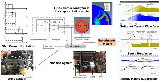
This paper presents a control method for OSRM drives, including motor start-up control, speed control, and torque ripple reduction. The torque generation mechanism of the OSRM is analyzed, considering the torque ripple characteristics of single-phase and two-phase hybrid traditional excitation current modes. Additionally, a step current excitation mode is proposed to solve the problem of low torque caused by the single-phase excitation mode and peak torque caused by the two-phase excitation mode. The step current excitation mode has two key parameters, namely, an excitation phase overlapping angle and a current reduction factor. Minimum torque ripple can be obtained by adjusting the parameters of the excitation current reduction factor and the excitation phase overlapping angle.
The paper is organized as follows. OSRM structure and control strategy are presented in
Section 2.
Section 3 presents the OSRM electromagnetic analysis, including single-phase and two-phase hybrid excitation modes and the torque ripple suppression method of OSRM based on step current excitation.
Section 4 introduces the OSRM drive system hardware platform and provides the experiment results of start-up and drive control, mechanical characteristic, speed regulation, and OSRM torque ripple suppression. Finally,
Section 5 concludes this paper.
2. OSRM Structure and Control Strategy
The working principle of OSRMs is the same as that of inner-rotor SRMs, which follows low reluctance principle, and the magnetic flux is always closed along the path of minimum reluctance [
16]. Switched reluctance drive (SRD) is generally composed of SRM, a power converter, a digital controller, a position sensor, a current sensor and torque sensor, as shown in
Figure 1 [
17]. The controller detects the relative position between the stator and rotor of SRM from the position signal provided by the position sensor, so as to select the excitation phase. According to the phase current from the current sensor, the current value of the current excitation phase is calculated, and the collected current is converted into digital signal and sent to the controller for calculation. The torque ripple provided by the torque sensor can be used in direct torque control, torque ripple suppression, and output power tests.
In this paper, an 8 kW five-phase 20/16 pole OSRM is considered for theoretical analysis, simulation, and experimental verification.
Figure 2a shows the single-phase circuit structure of the motor with an asymmetric half bridge;
Figure 2b shows the overall drive circuit, where each phase is independently controlled, leading to high reliability. The torque ripple of OSRM is large, mainly due to the characteristics of commutation excitation. However, the problem of large torque ripple can be solved by optimizing the designs of the motor body and motor control. When the ORSM is applied as the wheel hub motor of an EV, the motor can directly drive the wheel without a traditional power transmission system. Such a design can achieve small volume, high power and high efficiency, simplify the whole vehicle structure, reduce the whole vehicle weight, and is conductive to increasing the speed control range of EVs [
18].
3. Microscopic Electromagnetic Analysis of OSRM
This section presents a simulation-based analysis of OSRM using Magnet software. The stator and rotor initial position of the OSRM finite simulation model is shown in
Figure 3.
The tangential force contributes to the rotation of the motor. At the commutation time, the inductor current cannot be changed instantaneously, and the tangential force generated by the next excitation phase cannot reach the tangential force generated by the excitation phase before commutation. The decrease in the tangential force is dramatic, leading to torque drop at the commutation time and thereby causing large torque ripple.
At the aligned position, the OSRM normal forces are equal in magnitude and opposite in direction. If the two symmetrical normal forces are different in magnitude, the motor body will be deformed and the noise will be generated. The design of the finite element simulation assumes that the motor structure and electrical parameters are completely symmetrical, but there are errors and wear in the actual motor manufacturing and control operation process, resulting in the imbalance of normal force. The tangential force is analyzed and the method of eliminating torque ripple is studied.
3.1. Single-Phase and Two-Phase Hybrid Excitation Mode
The single-phase and two-phase hybrid excitation mode indicates that one-phase winding or two-phase winding may be excited at the same time. The excitation angle of each phase winding can be calculated by (1) where, if
a is small, the time slot of the two-phase excitation is minor or vice versa:
where
a (1 <
a < 2) is a constant,
Nr is the number of rotor poles, and
m is the number of motor phases.
The distribution of magnetic flux and electromagnetic force at different positions of the OSRM in hybrid excitation mode is simulated in
Figure 4. The flux density distribution of the hybrid excitation mode are between the single-phase excitation and the two-phase excitation modes at position A, B, and C position. Hybrid excitation mode is the combination of single-phase excitation and two-phase excitation. The angle of single-phase excitation and two-phase excitation depends on the turn-on angle.
The peak values of normal force and tangential force of the hybrid excitation mode at position A are close to those of the single-phase excitation mode and the two-phase excitation mode. At position B, the peak value of normal force of hybrid excitation mode is 3.2 times that of single-phase excitation mode and 0.8 times that of two-phase excitation mode; the peak value of tangential force of hybrid excitation mode is 3.3 times that of single-phase excitation mode and 0.83 times that of two-phase excitation mode; the peak values of normal force and tangential force of the hybrid excitation mode at position C are close to those of the single-phase excitation mode, which is significantly reduced comparing to the two-phase excitation mode.
Hybrid excitation can be view as the combination of the single-phase excitation and two-phase excitation mode, and offer a transitional torque region, which provides an intuitive basis for the study of OSRM torque ripple elimination.
3.2. Torque Ripple Suppression Method of OSRM Based on Step Current Excitation
Considering the large torque ripple in the traditional excitation method, a step current excitation mode is proposed, as shown in
Figure 5, where
I2 is the rated phase current reference,
I1 is the designated portion of the reference current
I2,
c is the proportional reduction coefficient, and Δ
θ is the overlap angle of excitation phase between preceding phase and the phase followed. So,
I1 indicates the first half of current excitation and
I2 indicates the second half of current excitation. Although the step excitation current mode reduces the tangential force of the overlapping part during two-phase excitation through the step current, it can effectively reduce the torque ripple.
The specific subsection expressions of the torque generated on the phase N winding of any OSRM under this excitation mode are given in (2).
where
θN2 =
θNon + (
θNoff −
θNon)/2 −
θ,
I1 =
c∙
I2 (0 <
c < 1), Δ
θ is the excitation overlap angle,
θN1 is the starting position of the minimum inductance of the phase N winding,
θon is the turn-on angle of the phase N winding, and
θoff is the turn-off angle of the phase N winding,
K = d
L(
θN)/d(
θ).
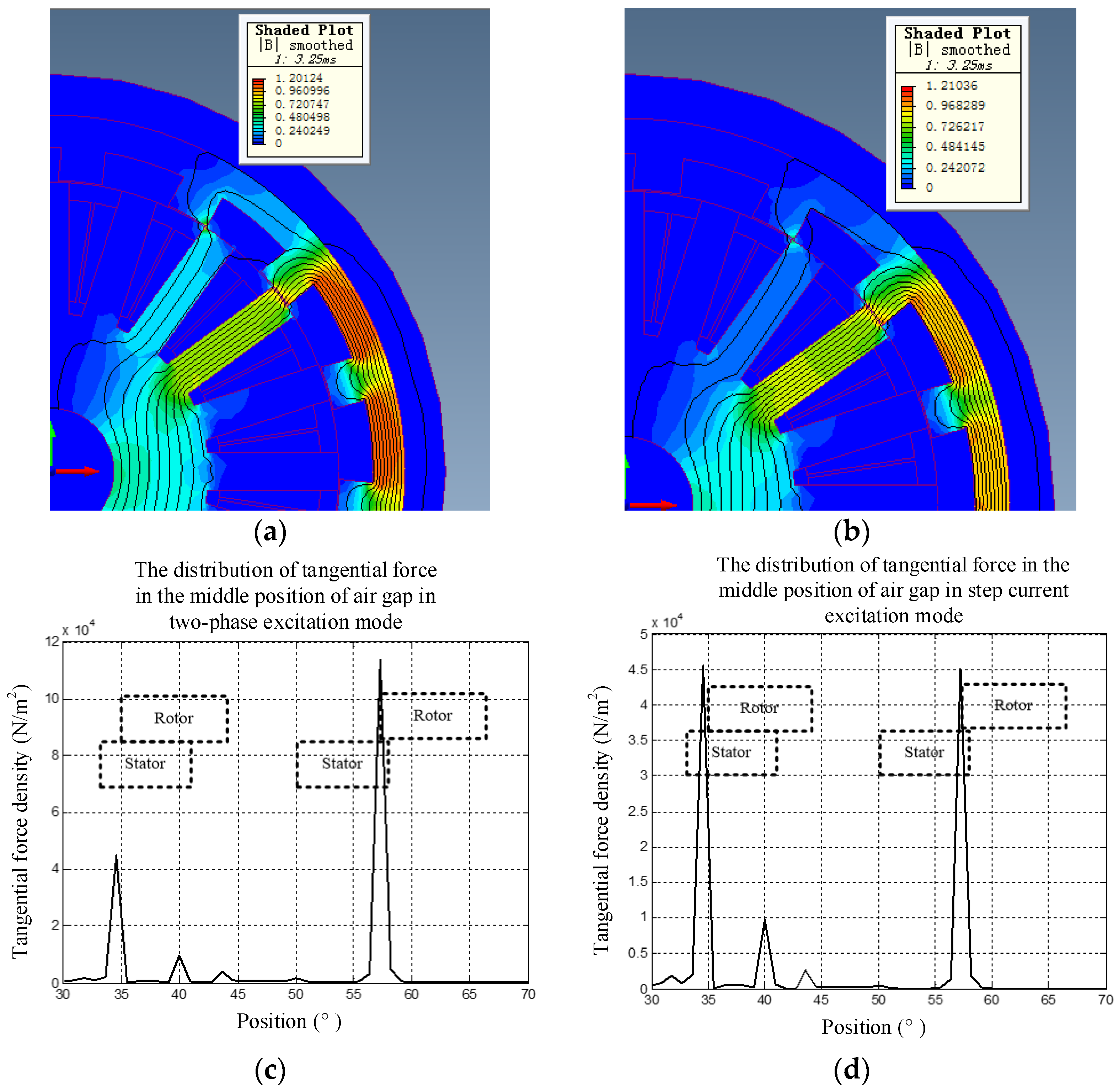
The step current excitation mode reduces the tangential force of the overlapped part via the step current so as to reduce the torque ripple. The tangential electromagnetic force distribution at the same rotor-stator position are extracted. The distribution of the magnetic flux and the tangential force density in the two excitation modes are presented in
Figure 6. From the distribution curve of tangential force density, it can be seen that the two-phase excitation mode produces a strong magnetic field during commutation, and the peak value of tangential force is more than twice of the previous tangential force. Compared with the two-phase excitation mode, the step current excitation mode produces uniform tangential force along the sweep contour [
15].
The torque versus position curve was simulated, where the speed of OSRM was set as 300 rpm, the rated current
I2 was taken as 5 A, finite element simulation is carried out for different
c and Δ
θ, as shown in
Figure 7. The optimization process start with tuning of Δ
θ with each fixed
I1 value, as illustrated in
Figure 7.
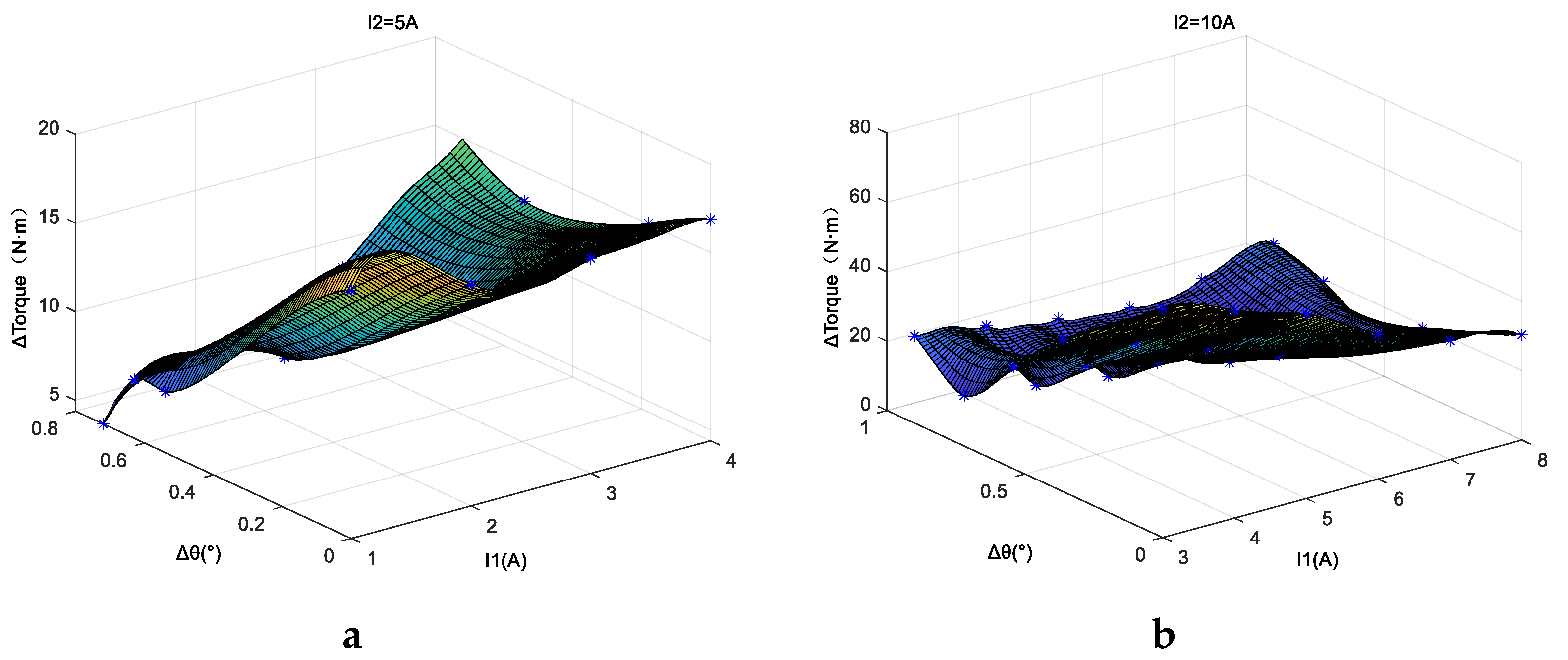
Finite element simulation was carried out for different Δ
θ and
c under the conditions of 300 r/min speed,
I2 = 5 A, and
I2 = 10 A, respectively. The characteristic curve of △
T with Δ
θ and
c is shown in
Figure 8, where optimal excitation parameters can be found based on the curved surface. The optimal excitation interval of
I2 = 5 A is the surrounding area with
c = 0.4 and Δ
θ = 0.7° as the center, and the optimal excitation interval of
I2 = 10 A is the surrounding area with
c = 0.4 and Δ
θ = 0.4° as the center. As can be seen in the step current excitation, the torque ripple of OSRM is affected by the excitation phase overlap angle Δ
θ and excitation current reduction coefficient
c. Adjust Δ
θ and c synchronously can reduce the torque ripple △
T quickly and effectively. New control structures based on this excitation mode and the traditional SRM double closed-loop control method can therefore be proposed. The minimum △
T is obtained by adjusting the step current excitation to suppress the torque ripple.
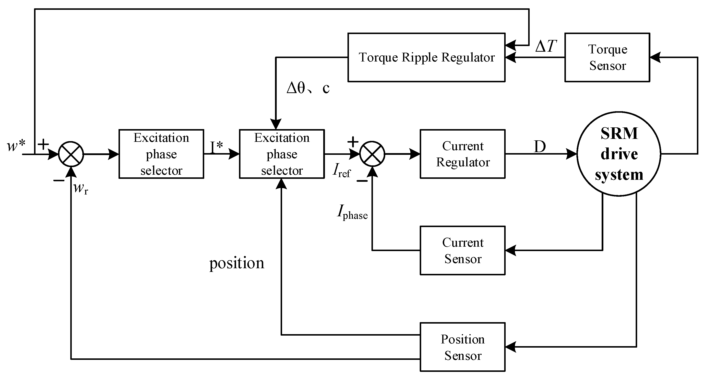
The control block diagram based on step current excitation mode and the traditional SRM double closed-loop control is shown in
Figure 9. In the double closed-loop control structure of the outer current loop and the inner speed loop, a torque ripple regulator is added. According to the given speed
w*, the calculated
Iref and the real-time calculated △
T, the optimal Δ
θ and
c are determined, and the minimum △
T is obtained by adjusting the stepped current excitation to realize the torque pulsation suppression.
The OSRM torque ripple is larger when using the traditional excitation method because of the characteristics of commutation excitation according to the position information. The torque ripple generated by the new step current excitation is smaller than that generated by the traditional excitation current. The torque ripple regulator is added to the traditional double closed-loop control. The optimal Δθ and c are determined by the given speed w*, the calculated Iref, and the real-time acquisition-calculated ΔT. The minimum ΔT is obtained by adjusting the step current excitation to suppress the torque ripple. The overlap angle of excitation phase Δθ and the factor c are important parameters affecting the torque ripple of OSRM.
5. Conclusions
In this study, speed control and ripple mitigation research for a five-phase OSRM was carried out. Microscopic level electromagnetic quantities and force density distribution in the OSRM were investigated under conventional single-phase and multi-phase excitation. A new step current excitation method based on a hybrid excitation mode was proposed, where the step amplitude and overlapping angle of the adjacent phases were finely tuned for the best torque-mitigation effect. The prototype machine and its drive testbed are built, and the speed control loop with torque mitigation was implemented on a digital signal controller. Experiments were carried out to verify the soft-start, no-load and load condition operations; these experiments indicated that the OSRM torque ripple was well suppressed under the proposed step current excitation method.
As this research’s main focus was on speed control and torque mitigation, the efficiency of the OSRM only measured at 72.18%, which is within the practical range but is considered low. Another practical issue is the heat dissipation. In this study, OSRM was tested in an open rack condition in which the tire was not installed. Therefore, efficiency improvement with heat dissipation research will be carried out in future study.


 ,
, 


