
Social Grouping Algorithm Aided Maximum Power Point Tracking Scheme for Partial Shaded Photovoltaic Array

 ,
,  ,
,  and
and 
Abstract
:1. Introduction
- Voltage regulations and enhanced compatibility between the PV and load;
- Ensuring maximum power point tracking (MPPT).
2. PV Cell Modelling and Partial Shading Impact
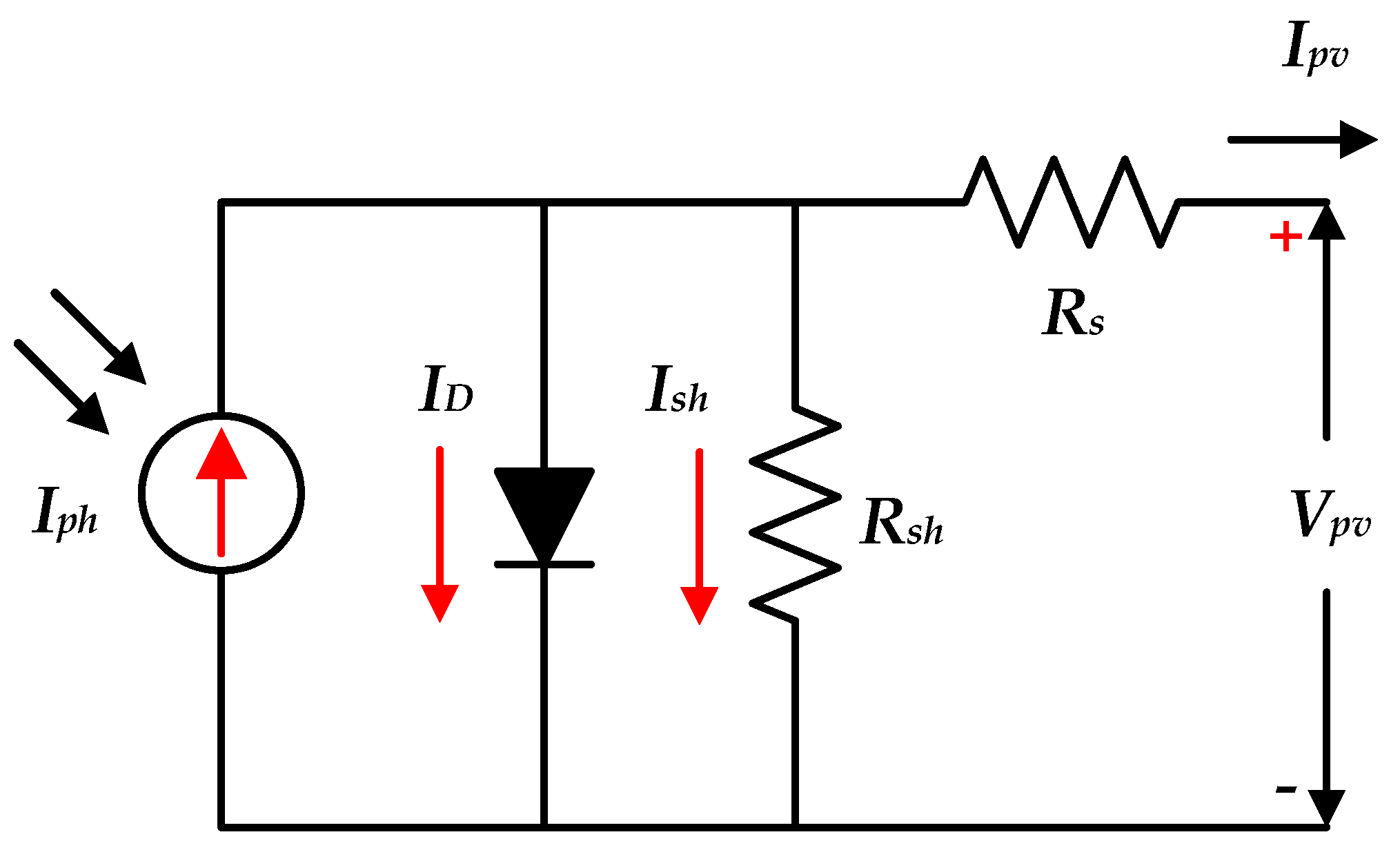
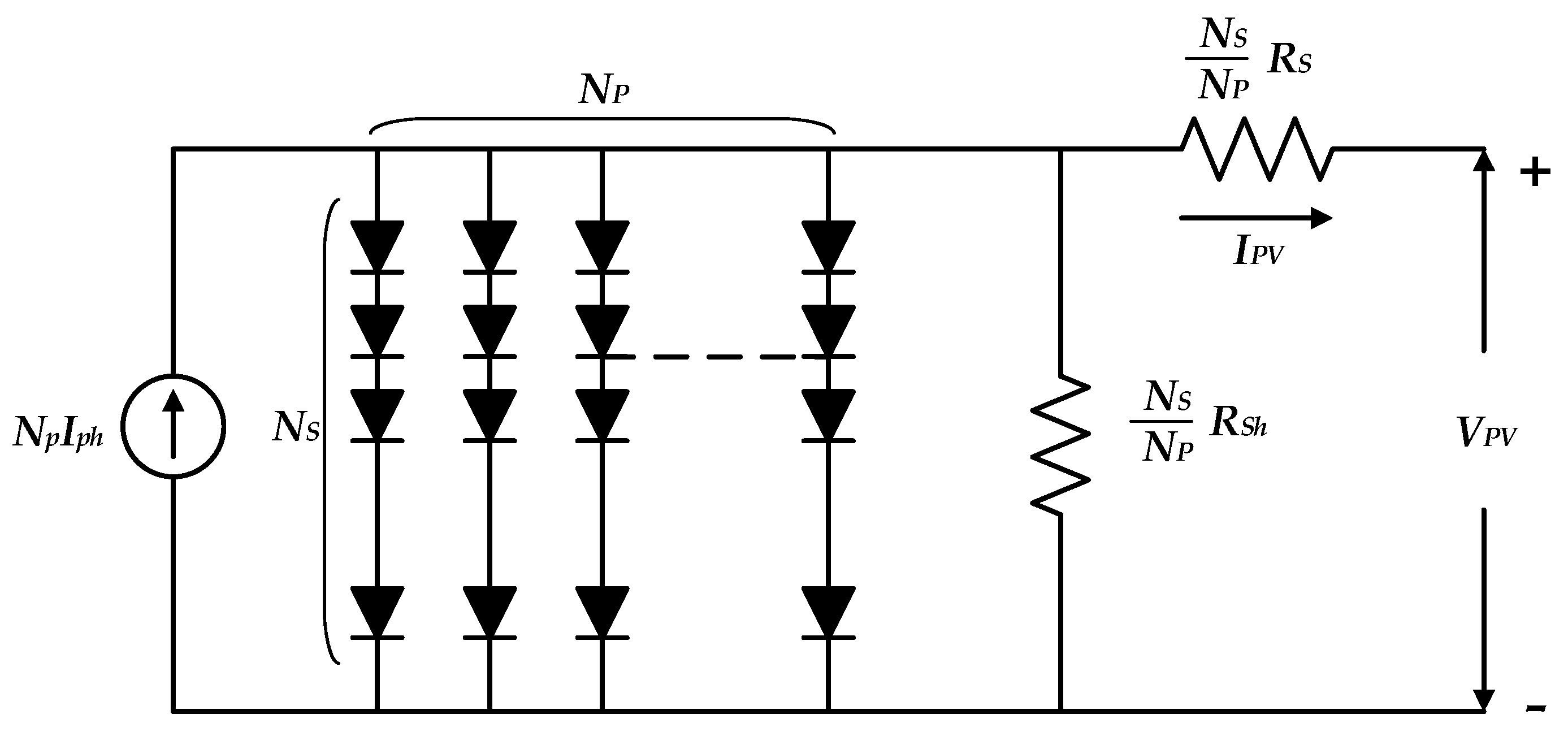
2.1. PV Modelling
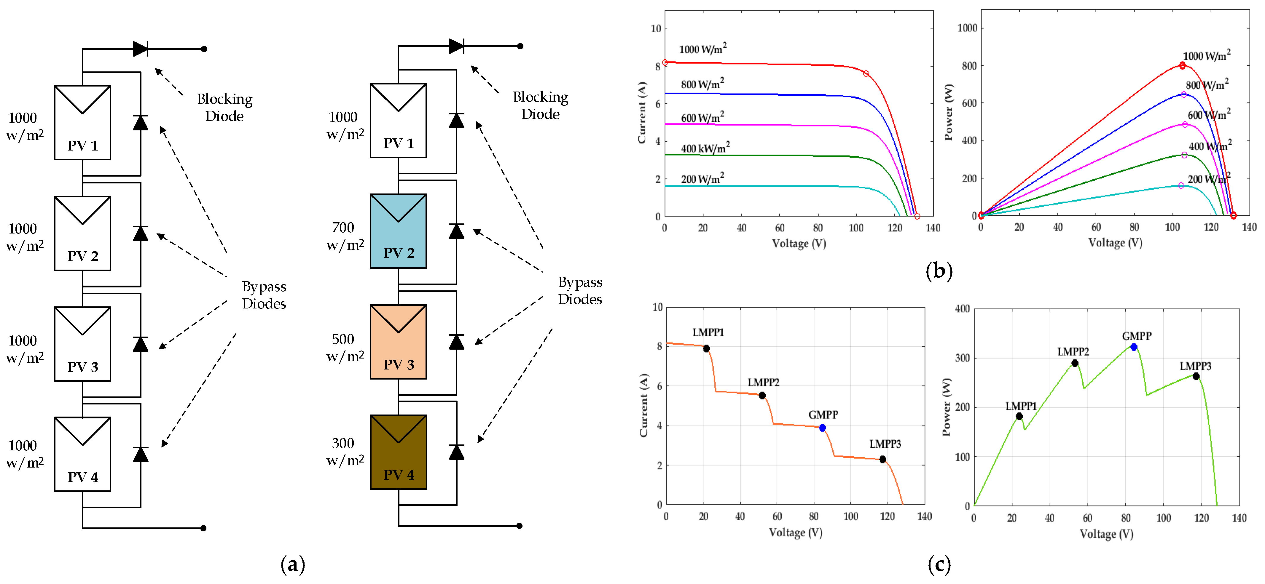
2.2. Partial Shading Effects
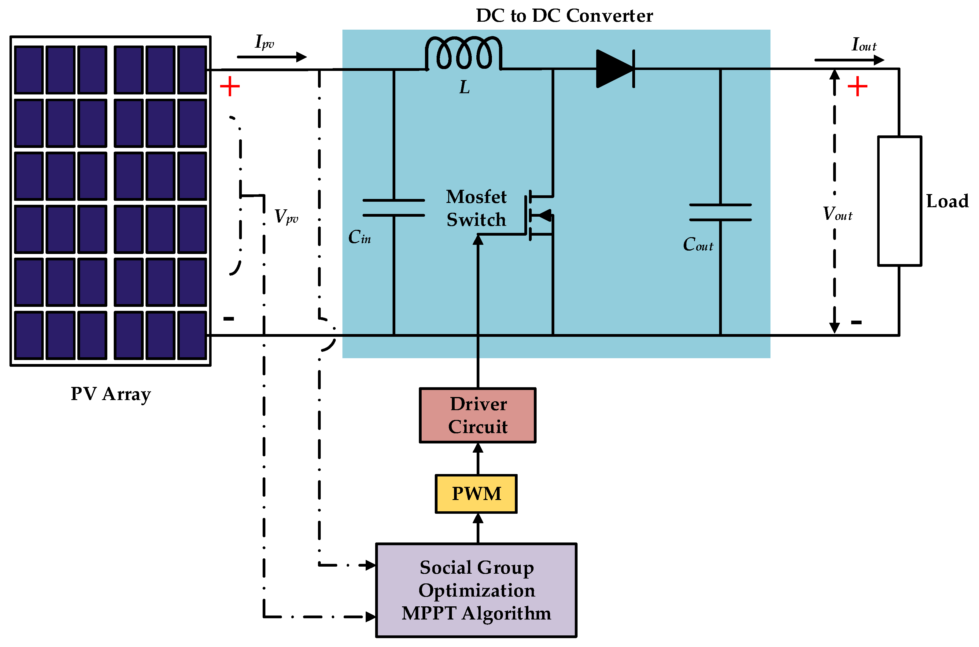
2.3. Boost Converter Design
3. SGO-Based MPPT
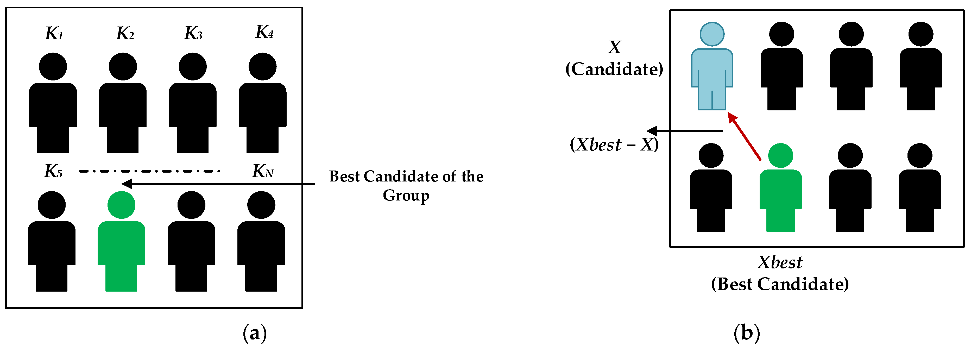
3.1. SGO Principles
3.1.1. Improving Phase
3.1.2. Acquiring Phase
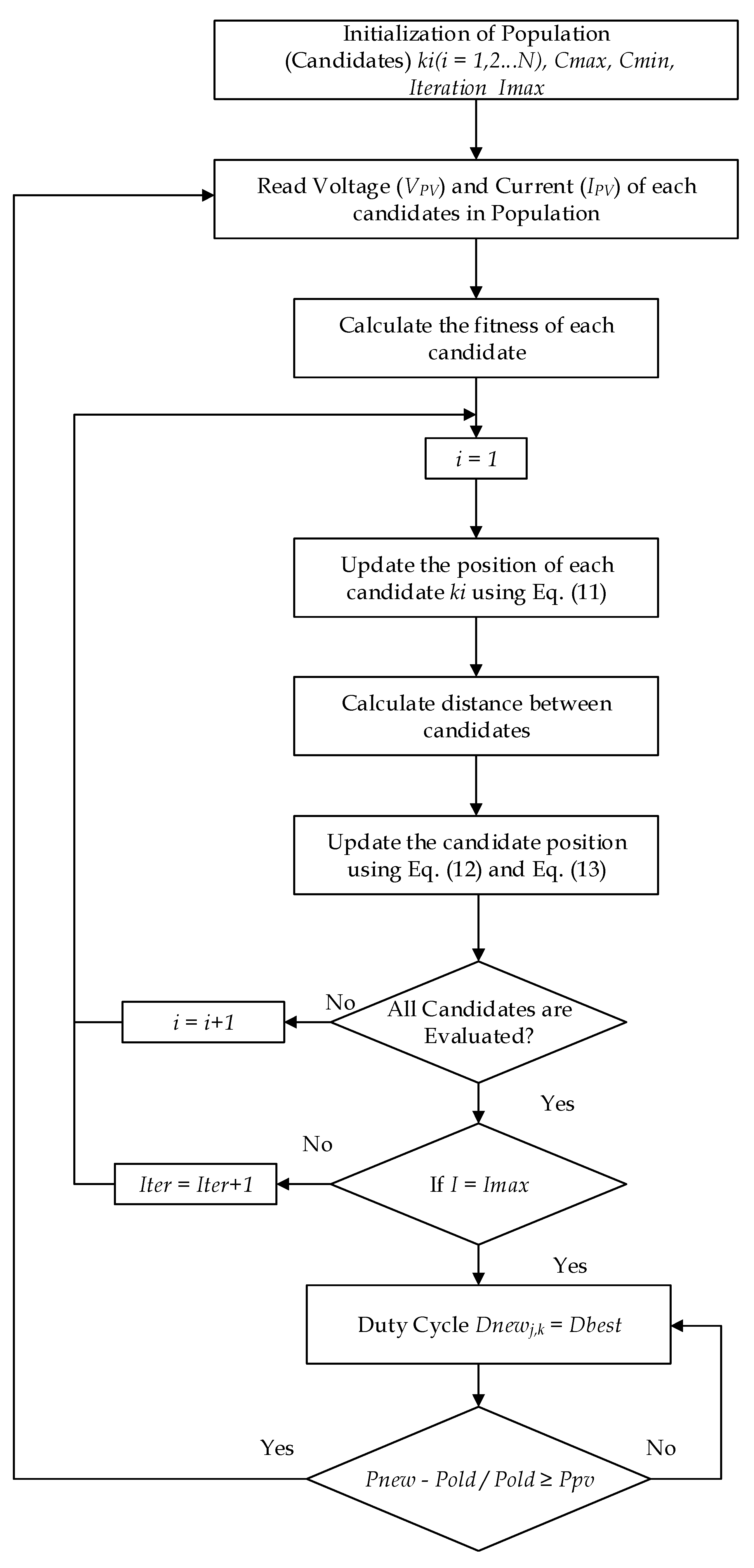
3.2. SGO–MPPT Implementation
3.2.1. Initialization Phase
3.2.2. Improving Phase
- Dnewjk—New Solution of Candidate;
- C—Self Introspection (0 to 1);
- Doldjk—Existing Solution;
- r—Random Number (0 to 1);
- (Gbest(k) − Doldjk)—Influence of the best Candidate.
3.2.3. Acquiring Phase
4. Results and Discussion
4.1. Simulation Methodology
4.2. Case Studies
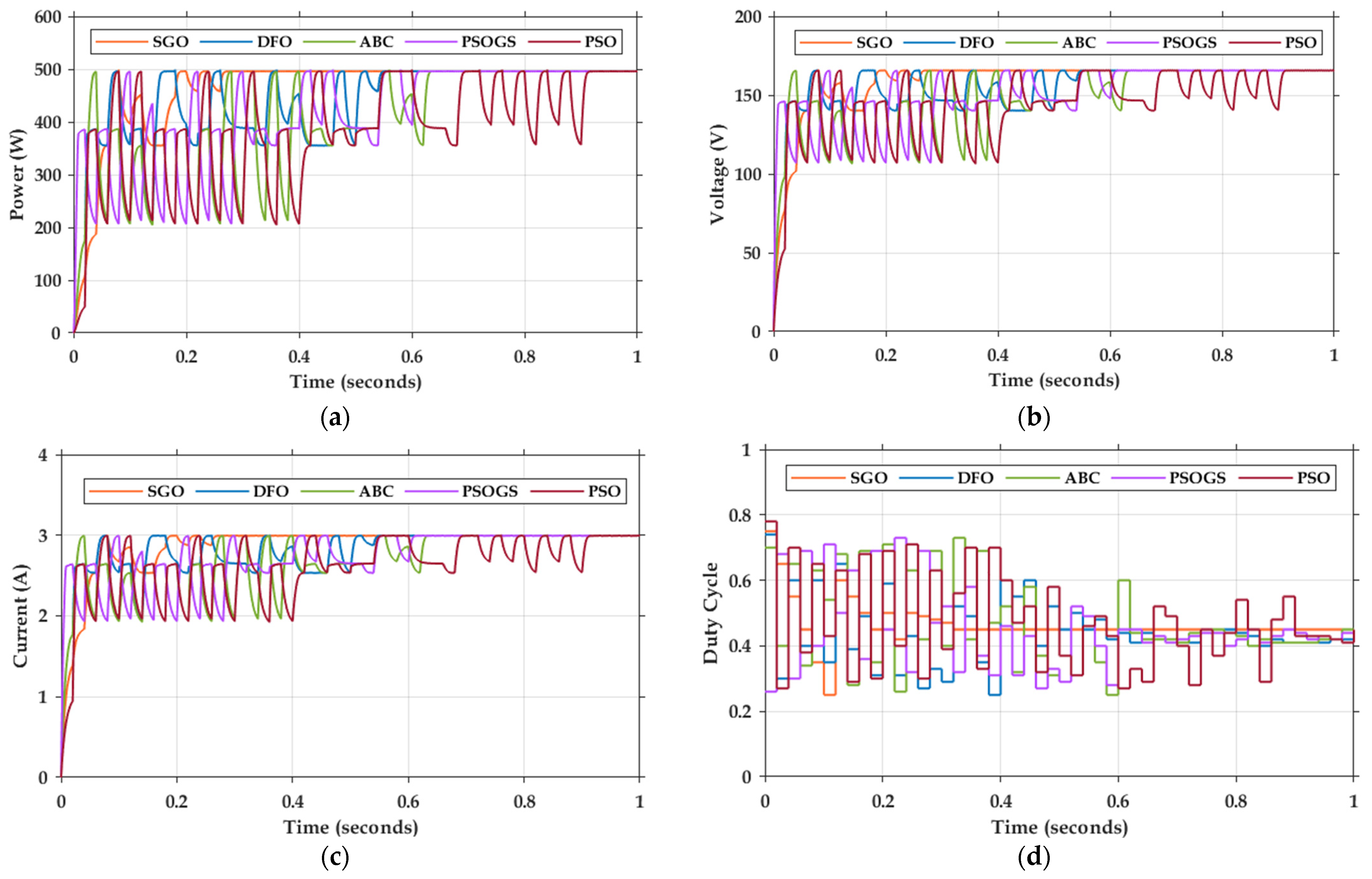
4.2.1. Case 1
4.2.2. Case 2
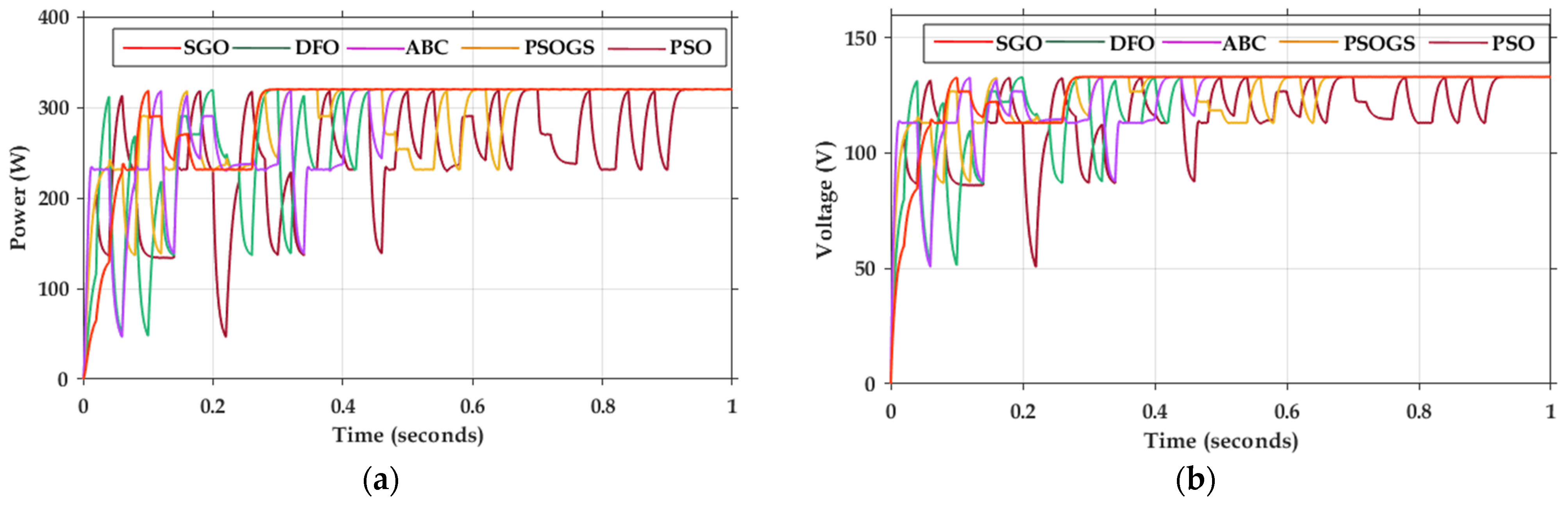
4.2.3. Case 3
4.3. Comparative Analysis
5. Conclusions
Author Contributions
Funding
Institutional Review Board Statement
Informed Consent Statement
Data Availability Statement
Acknowledgments
Conflicts of Interest
Nomenclature
| PV | Photovoltaic |
| MPPT | Maximum Power Point Tracking |
| PS | Partial Shading |
| SGO | Social Group Optimization |
| PSO | Particle Swarm Optimization |
| DFO | Dragon Fly Algorithm |
| ABC | Artificial Bee Colony Algorithm |
| Vmp | Peak Operating Voltage |
| P&O | Perturb and Observe |
| INC | Incremental Conductance |
| S | Separation |
| c | Cohesion |
| e | Position of the Enemy |
| w | Inertia Weight |
| OCV | Open Circuit Voltage |
| SCC | Short Circuit Current |
| GA | Genetic Algorithm |
| PSOGS | Particle Swarm Optimization Gravitation Search |
| ANN | Artificial Neural Network |
| DE | Differential Evolution |
| ACO | Ant Colony Algorithm |
| GWO | Grey Wolf Optimizer |
| STC | Standard Test Conditions |
| GMPP | Global Maximum Power Point |
| a | Alignment |
| f | Position of the Food |
| C1, C2 | Cognitive Factor |
| GO | Regulatory Co-efficient |
References
- Shaw, S.; Libby, C.; Scott, M.; Grice, L.N.; Shaikh, N.; Peterson, C.; Ladwig, K. The Global Circular Economy for the Electric Power Industry and Opportunities for Solar Photovoltaics. In Proceedings of the 2021 IEEE 48th Photovoltaic Specialists Conference (PVSC), Fort Lauderdale, FL, USA, 20–25 June 2021. [Google Scholar] [CrossRef]
- Renewables 2020. Available online: https://www.iea.org/reports/renewables-2020 (accessed on 1 March 2022).
- Kumar, J.C.R.; Majid, M.A. Renewable energy for sustainable development in India: Current status, future prospects, challenges, employment, and investment opportunities. Energy Sustain. Soc. 2020, 10, 1–36. [Google Scholar] [CrossRef]
- D’Adamo, I.; Gastaldi, M.; Morone, P. The post COVID-19 green recovery in practice: Assessing the profitability of a policy proposal on residential photovoltaic plants. Energy Policy 2020, 147, 111910. [Google Scholar] [CrossRef]
- Dhimish, M.; Holmes, V.; Mather, P.; Sibley, M. Novel hot spot mitigation technique to enhance photovoltaic solar panels output power performance. Sol. Energy Mater. Sol. Cells 2018, 179, 72–79. [Google Scholar] [CrossRef] [Green Version]
- Bollipo, R.B.; Mikkili, S.; Bonthagorla, P.K. Hybrid, optimal, intelligent and classical PV MPPT techniques: A review. CSEE J. Power Energy Syst. 2020, 19, 9–33. [Google Scholar]
- Ahmad, R.; Murtaza, A.F.; Sher, H.A. Power tracking techniques for efficient operation of photovoltaic array in solar applications—A review. Renew. Sustain. Energy Rev. 2019, 101, 82–102. [Google Scholar] [CrossRef]
- FerozMirza, A.; Mansoor, M.; Ling, Q.; Khan, M.I.; Aldossary, O.M. Advanced Variable Step Size Incremental Conductance MPPT for a Standalone PV System Utilizing a GA-Tuned PID Controller. Energies 2020, 13, 4153. [Google Scholar] [CrossRef]
- Shahid, H.; Kamran, M.; Mehmood, Z.; Saleem, M.Y.; Mudassar, M.; Haider, K. Implementation of the novel temperature controller and incremental conductance MPPT algorithm for indoor photovoltaic system. Sol. Energy 2018, 163, 235–242. [Google Scholar] [CrossRef]
- Ammar, H.H.; Azar, A.T.; Shalaby, R.; Mahmoud, M.I. Metaheuristic optimization of fractional order incremental conductance (FO-INC) maximum power point tracking (MPPT). Complexity 2019, 2019, 7687891. [Google Scholar] [CrossRef]
- Paul, S.; Thomas, J. Comparison of MPPT using GA optimized ANN employing PI controller for solar PV system with MPPT using incremental conductance. In Proceedings of the 2014 International Conference on Power Signals Control and Computations (EPSCICON), Thrissur, India, 6–11 January 2014. [Google Scholar] [CrossRef]
- Ibrahim, A.W.; Shafik, M.B.; Ding, M.; Sarhan, M.A.; Fang, Z.; Alareqi, A.G.; Almoqri, T.; Al-Rassas, A.M. PV maximum power-point tracking using modified particle swarm optimization under partial shading conditions. Chin. J. Electr. Eng. 2020, 6, 106–121. [Google Scholar] [CrossRef]
- Mirza, A.F.; Ling, Q.; Javed, M.Y.; Mansoor, M. Novel MPPT techniques for photovoltaic systems under uniform irradiance and Partial shading. Sol. Energy 2019, 184, 628–648. [Google Scholar] [CrossRef]
- Eltamaly, A.M.; Farh, H.M.H. Dynamic global maximum power point tracking of the PV systems under variant partial shading using hybrid GWO-FLC. Sol. Energy 2019, 177, 306–316. [Google Scholar] [CrossRef]
- Ulaganathan, M.S.; Devaraj, D. A novel MPPT controller using Neural Network and Gain-Scheduled PI for Solar PV system under rapidly varying environmental condition. J. Intell. Fuzzy Syst. 2019, 37, 1085–1098. [Google Scholar] [CrossRef]
- Lin, W.; Lian, Z.; Gu, X.; Jiao, B. A Local and Global Search Combined Particle Swarm Optimization Algorithm and Its Convergence Analysis. Math. Probl. Eng. 2014, 2014, 905712. [Google Scholar] [CrossRef]
- Figueiredo, S.; e Silva, R.N.A.L. Hybrid MPPT Technique PSO-P&O Applied to Photovoltaic Systems Under Uniform and Partial Shading Conditions. IEEE Lat. Am. Trans. 2021, 19, 1610–1617. [Google Scholar] [CrossRef]
- Tavakoli, A.; Forouzanfar, M. A self-constructing Lyapunov neural network controller to track global maximum power point in PV systems. Int. Trans. Electr. Energy Syst. 2020, 30, 12391. [Google Scholar] [CrossRef]
- Tey, K.S.; Mekhilef, S.; Yang, H.-T.; Chuang, M.-K. A Differential Evolution Based MPPT Method for Photovoltaic Modules under Partial Shading Conditions. Int. J. Photoenergy 2014, 2014, 945906. [Google Scholar] [CrossRef] [Green Version]
- Priyadarshi, N.; Ramachandaramurthy, V.K.; Padmanaban, S.; Azam, F. An ant colony optimized MPPT for standalone hybrid PV-wind power system with single Cuk converter. Energies 2019, 12, 167. [Google Scholar] [CrossRef] [Green Version]
- Soufyane Benyoucef, A.; Chouder, A.; Kara, K.; Silvestre, S. Artificial bee colony based algorithm for maximum power point tracking (MPPT) for PV systems operating under partial shaded conditions. Appl. Soft Comput. 2015, 32, 38–48. [Google Scholar] [CrossRef] [Green Version]
- Darcy GnanaJegha, A.; Subathra, M.S.P.; Manoj Kumar, N.; Subramaniam, U.; Padmanaban, S. A High Gain DC-DC Converter with Grey Wolf Optimizer Based MPPT Algorithm for PV Fed BLDC Motor Drive. Appl. Sci. 2020, 10, 2797. [Google Scholar] [CrossRef]
- Zhang, Y.; Jin, Z. Group teaching optimization algorithm: A novel metaheuristic method for solving global optimization problems. Expert Syst. Appl. 2020, 148, 113246. [Google Scholar] [CrossRef]
- Motahhir, S.; El Hammoumi, A.; El Ghzizal, A. The most used MPPT algorithms: Review and the suitable low-cost embedded board for each algorithm. J. Clean. Prod. 2020, 246, 118983. [Google Scholar] [CrossRef]
- Rezk, H.; Fathy, A.; Abdelaziz, A.Y. A comparison of different global MPPT techniques based on meta-heuristic algorithms for photovoltaic system subjected to partial shading conditions. Renew. Sustain. Energy Rev. 2017, 74, 377–386. [Google Scholar] [CrossRef]
- Zafar, M.H.; Al-shahrani, T.; Khan, N.M.; Feroz Mirza, A.; Mansoor, M.; Qadir, M.U.; Naqvi, R.A. Group Teaching Optimization Algorithm Based MPPT Control of PV Systems under Partial Shading and Complex Partial Shading. Electronics 2020, 9, 1962. [Google Scholar] [CrossRef]
- Satapathy, S.; Naik, A. Social group optimization (SGO): A new population evolutionary optimization technique. Complex Intell. Syst. 2016, 2, 173–203. [Google Scholar] [CrossRef] [Green Version]
- Cherukuri, S.K.; Balachandran, P.K.; Kaniganti, K.R.; Buddi, M.K.; Butti, D.; Devakirubakaran, S.; Alhelou, H.H. Power Enhancement in Partial Shaded Photovoltaic System Using Spiral Pattern Array Configuration Scheme. IEEE Access 2021, 9, 123103–123116. [Google Scholar] [CrossRef]
- Palpandian, M.; Winston, D.P.; Kumar, B.P.; Kumar, C.S.; Babu, T.S.; Alhelou, H.H. A New Ken-Ken Puzzle Pattern Based Reconfiguration Technique for Maximum Power Extraction in Partial Shaded Solar PV Array. IEEE Access 2021, 9, 65824–65837. [Google Scholar] [CrossRef]
- Winston, P.; Kumar, B.P.; Christabel, S.C.; Chamkha, A.J.; Sathyamurthy, R. Maximum Power Extraction in Solar Renewable Power System—A Bypass Diode Scanning Approach. Comput. Electr. Eng. 2018, 70, 122–136. [Google Scholar] [CrossRef]
- Mansoor, M.; Mirza, A.F.; Ling, Q.; Javed, M.Y. Novel Grass Hopper optimization based MPPT of PV systems for complex partial shading conditions. Sol. Energy 2020, 198, 499–518. [Google Scholar] [CrossRef]
- Sundaram, B.M.; Manikandan, B.V.; Kumar, B.P.; Winston, D.P. Combination of Novel Converter Topology and Improved MPPT Algorithm for Harnessing Maximum Power from Grid Connected Solar PV Systems. J. Electr. Eng. Technol. 2019, 14, 733–746. [Google Scholar] [CrossRef]
- Singh, G.K.; Kaur, A. Maximum Power Point Tracking in Photovoltaic Solar Energy Systems using Hybrid PSO-GSA Method. Int. J. Eng. Res. Technol. 2015, 4, 391–394. [Google Scholar]
- Raman, G.; Raman, G.; Manickam, C.; Ganesan, S.I. Dragonfly Algorithm Based Global Maximum Power Point Tracker for Photovoltaic Systems. Lect. Notes Comput. Sci. 2016, 9712, 211–219. [Google Scholar] [CrossRef]
- Shams, I.; Mekhilef, S.; Tey, K.S. Maximum Power Point Tracking Using Modified Butterfly Optimization Algorithm for Partial Shading, Uniform Shading, and Fast Varying Load Conditions. IEEE Trans. Power Electron. 2021, 36, 5569–5581. [Google Scholar] [CrossRef]
- Parvaneh, M.H.; Khorasani, P.G. A new hybrid method based on fuzzy logic for maximum power point tracking of photovoltaic systems. Energy Rep. 2020, 6, 1619–1632. [Google Scholar] [CrossRef]
- Yousri, D.; Babu, T.S.; Allam, D.; Ramachandaramurthy, V.K.; Etiba, M.B. A Novel Chaotic Flower Pollination Algorithm for Global Maximum Power Point Tracking for Photovoltaic System under Partial Shading Conditions. IEEE Access 2019, 7, 121432–121445. [Google Scholar] [CrossRef]


| Specifications | Values |
|---|---|
| Maximum Power (Pmax) | 200.143 W |
| Maximum Power Voltage (Vmp) | 26.3 V |
| Maximum Power Current (Imp) | 7.61 A |
| Open Circuit Voltage (Voc) | 32.9 V |
| Short Circuit Current (Isc) | 8.21 A |
| Temperature Coefficient of Voc | −0.1230 V/K |
| Temperature Coefficient of Isc | 0.0032 A/K |
| Number of Cells per Module | 54 |
| MPPT Method | Tuning Parameters |
|---|---|
| SGO | Cmin = 0.1, Cmax = 0.9 |
| ABC [21] | Wmax = 0.9, Wmin = 0.4 |
| PSOGS [33] | C1 = 0.5, C2 = 1.5, G0 = 1, W = 0.9 |
| DFO [34] | S = 0.1, a = 0.1, c = 0.7, f = 1, e = 1 |
| PSO [35] | C1max = C2max = 2, C1min = C2min = 1, Wmax = 1, Wmin = 0.1 |
| Case Study | Solar Irradiance (W/m2) | Pmax (W) | |||
|---|---|---|---|---|---|
| PV 1 | PV 2 | PV 3 | PV 4 | ||
| Case 1 | 1000; 700; 300 * | 1000; 700; 300 | 1000; 700; 300 | 1000; 700; 300 | 798; 557.8; 227.3 |
| Case 2 | 500 | 800 | 1000 | 900 | 504.2 |
| Case 3 | 800 | 300 | 700 | 500 | 322.2 |
| Cases | Algorithms | Average Number of Iteration | GMPP (W) | Power Tracked (W) | Efficiency (%) | RE (%) | MAE | RMSE | Convergence Time (s) |
|---|---|---|---|---|---|---|---|---|---|
| Case 1 | SGO | 7.20 | 798 1, 557.8 2, 227.3 3 | 797.5, 557.3, 226.8 | 99.93 | 0.124 | 1.464 | 0.856 | 0.22 |
| DFO | 10.28 | 797, 556.8, 226.3 | 99.87 | 0.249 | 2.929 | 1.711 | 0.3 | ||
| ABC | 11.26 | 796, 555.8, 225.3 | 99.74 | 0.500 | 5.858 | 3.423 | 0.38 | ||
| PSOGS | 12.19 | 795, 554.8, 224.3 | 99.62 | 0.752 | 8.787 | 5.134 | 0.6 | ||
| PSO | 14.33 | 794, 553.8, 223.3 | 99.49 | 1.006 | 11.716 | 6.846 | 0.7 | ||
| Case 2 | SGO | 10.68 | 504.2 | 503.5 | 99.86 | 0.139 | 2.050 | 1.198 | 0.24 |
| DFO | 13.45 | 503.1 | 99.78 | 0.219 | 3.222 | 1.883 | 0.46 | ||
| ABC | 14.26 | 502.1 | 99.58 | 0.418 | 6.151 | 3.594 | 0.56 | ||
| PSOGS | 16.05 | 501.5 | 99.46 | 0.538 | 7.908 | 4.621 | 0.62 | ||
| PSO | 18.34 | 501 | 99.36 | 0.639 | 9.373 | 5.477 | 0.87 | ||
| Case 3 | SGO | 11.12 | 322.2 | 321.5 | 99.76 | 0.218 | 2.053 | 1.196 | 0.26 |
| DFO | 14.90 | 320.7 | 99.53 | 0.468 | 4.393 | 2.567 | 0.5 | ||
| ABC | 17.22 | 320.1 | 99.34 | 0.656 | 6.151 | 3.594 | 0.59 | ||
| PSOGS | 21.62 | 319.6 | 99.19 | 0.814 | 7.615 | 4.450 | 0.69 | ||
| PSO | 23.18 | 318.5 | 98.85 | 1.162 | 10.837 | 6.332 | 0.89 |
Publisher’s Note: MDPI stays neutral with regard to jurisdictional claims in published maps and institutional affiliations. |
© 2022 by the authors. Licensee MDPI, Basel, Switzerland. This article is an open access article distributed under the terms and conditions of the Creative Commons Attribution (CC BY) license (https://creativecommons.org/licenses/by/4.0/).
Share and Cite
Vadivel, S.; Sengodan, B.C.; Ramasamy, S.; Ahsan, M.; Haider, J.; Rodrigues, E.M.G. Social Grouping Algorithm Aided Maximum Power Point Tracking Scheme for Partial Shaded Photovoltaic Array. Energies 2022, 15, 2105. https://doi.org/10.3390/en15062105
Vadivel S, Sengodan BC, Ramasamy S, Ahsan M, Haider J, Rodrigues EMG. Social Grouping Algorithm Aided Maximum Power Point Tracking Scheme for Partial Shaded Photovoltaic Array. Energies. 2022; 15(6):2105. https://doi.org/10.3390/en15062105
Chicago/Turabian StyleVadivel, Srinivasan, Boopathi C. Sengodan, Sridhar Ramasamy, Mominul Ahsan, Julfikar Haider, and Eduardo M. G. Rodrigues. 2022. "Social Grouping Algorithm Aided Maximum Power Point Tracking Scheme for Partial Shaded Photovoltaic Array" Energies 15, no. 6: 2105. https://doi.org/10.3390/en15062105
APA StyleVadivel, S., Sengodan, B. C., Ramasamy, S., Ahsan, M., Haider, J., & Rodrigues, E. M. G. (2022). Social Grouping Algorithm Aided Maximum Power Point Tracking Scheme for Partial Shaded Photovoltaic Array. Energies, 15(6), 2105. https://doi.org/10.3390/en15062105