1. Introduction
The creation of a durable and safe transport infrastructure in the northern regions of the Russian Federation will not only open a short access to the Northern Sea Route, but will also serve the development of cities, connecting remote regions of Russia both with each other and with its central part. This requires the construction of new bridges for transportation of people, goods and various type of energies.
For the construction of transport infrastructure such as highways, railway bridges and pipeline bridges in the conditions of the Far North (Artic Circle), it is necessary to develop a modern regulatory and technological base, which will ensure both geotechnical safety during the construction and exploitation of transport infrastructure in difficult climatic conditions, and the use of new fiber-reinforced polymers (FRP) to replace traditionally used building materials.
The need to replace traditional building materials is due to the fact that fiber-reinforced polymers have high strength characteristics with a low density. This type of material is also resistant to aggressive environments and extremely low temperatures, as well as its fluctuations. At the same time, the concrete reinforced and metal structures, on the contrary, are susceptible to destruction from exposure to salts and low temperatures. Thus, FRP is an alternative for traditional used building materials [
1].
However, FRP have not only advantages, but also disadvantages. The fiber-reinforced polymers disadvantages are anisotropy (reduced transversal strength), the relatively low elastic modulus, the low long-term strength due to stress rupture and a significant variation in the values of mechanical characteristics [
1,
2]. Therefore, in order to use new building materials, it is necessary to create a regulatory and technological base, including on the basis of research in modern laboratory conditions. In addition, it is necessary to improve design methods, as well as to update the requirements for the current maintenance of load-bearing structures of artificial structures, taking into account the specifics of the properties of these materials.
Such studies related to the use of hybrid materials or all-composite structures in bridge construction solve the problem of constructive search aimed at expanding the possibilities of using sufficiently durable, lightweight and resistant to aggressive environments materials. In this regard, it should be noted that anisotropic properties are not a disadvantage in full. On the contrary, finding the right combination of matrix and filler components will allow you to create materials with the required values of strength, modulus of elasticity, resistance to external environments and other properties. At the same time, the features of fiber-reinforced polymers are such that it allows for equal strength of structures.
According to a report from Prof. Dr. Thomas Keller, “Use of fiber-reinforced polymers in bridge construction”, under the term “the hybrid structures” is understood the following: components of the bridge superstructure (girders, beams, deck slabs, pylons, stay cable, etc.) consisting, on the one hand, of traditional materials (steel, concrete, wood) and, on the other hand, of FRP. The abutments and piers usually consist of traditional materials [
1]. Using components with different characteristics of FRP, it is possible to create plastics with the required properties for various load-bearing structures and for certain operating conditions.
A survey of the bridges with fiber-reinforced plastics from publications [
1,
2] permits a classification into two main categories. The first category is a traditional bridge concept, in which traditional materials are simply substituted by FRP. The second category is a concept which tries to take into account the new properties of the FRP materials. It is also called material-adapted concepts. In material-adapted concepts, the basic idea is to use FRP where its advantages can be best utilized [
1]. However, at the moment, there are no generally accepted and formalized design methods in the state standard that allow adapting structures to the properties of new fiber-reinforced materials.
For now, the construction of bridges made of FRP is more experimental than basic. Nevertheless, from the 1980s to recently, about four hundred bridges of FRP have been built. There are many types of bridges such as girder, arch, suspension and cable-stayed structures, and also geocell-reinforced embankment on approach bridges [
1,
2,
3].
The hybrid bridges are most effective and advanced from the point of view of the values of the transmitted live load at one moment. For example, the road hybrid bridges over the Pashenka River in Russia with 18 m long single span [
4,
5] and a 21 m long single span bridge in Poland [
6]. These bridges consists of fiberglass beams with a concrete slab. Moreover, these bridges differ from each other in manufacturing methods: pultrusion for the Russian bridge and vacuum infusion for the Polish one. During the tests of the bridge over the Pashenka River, the live load was equal to 106 ton-force [
4,
5].
At the same time, the slab of the bridge in Poland was made of fiberglass reinforcement concrete. In addition, hybrid bridges made of carbon-fiber continuous beams with a reinforced concrete slab were also built in Spain [
7].
There are also hybrid and all-composite truss bridges [
1,
2], arch bridges [
2,
8], drawbridges [
2,
9], cable-stayed bridges [
1,
2,
10] and suspension bridges [
2,
11,
12,
13,
14]. In some cases, the design itself is already successful adapted to FRP, for example, the truss bridges. In other cases, constructions of orthotropic slabs with a system of ribs in the form of honeycombs or cellular profiles were created for the construction of bridges from FRP [
1,
2]. In addition, there are cases when, for the use FRP girders, it was needed to increase the bending stiffness by increasing the height of the cross-section [
10]. Thus, the small modulus of elasticity was compensated by an increase in the moment of inertia.
It should be noted that the issue of non-destructive testing and monitoring is not less important for bridges built from FRP, because these materials are still completely unexplored. From the review of another research it can be seen that there are methods that allow non-destructive testing of fiber-reinforced concrete [
15], such as for a bridge from FRP in Poland [
6], as well as noncontact vibration technique for health monitoring of structural cables of suspension bridges and cable-stayed bridges [
16].
From the examples of this FRP bridge, it can be seen that the load-bearing capacity of structures was achieved by adapting existing design principles to the properties of FRP [
1,
2,
3,
4,
5,
6,
7,
8,
9,
10,
11,
12,
13,
14], which allowed to reduce the influence of the disadvantages of FRP and ensure the effective use of their strength properties.
Further research is appropriate to carry out in order to solve existing transport problems. For example, to improve pedestrian safety when they are crossing roads and providing direct access to transport and civil infrastructure. A suspension system is a rational type of construction that allows for the intersection of highways without the installation of additional intermediate supports on the intersected road. However, the use of FRP girders in suspension and cable-stayed bridges is complicated, not only by the need to ensure strength and stiffness from dead and live loads, but also by the need to conduct special studies to ensure aerodynamic stability.
Research Significance
First of all, the bridge design was chosen for this study. It is a single-span hybrid suspension bridge with an FRP superstructure. Thus, the significance of the main results, that was obtained from a previous stage of research work, consists in the determination of conditions and form of application of the fiber-reinforced polymer in the pedestrian suspension bridges. For this, the finite-element calculations of models of suspension hybrid bridges with pultrusion fiberglass superstructure were performed. The method of calculating models is described in
Section 2.1.
Based on the results of numerical calculation, the structural additions to the suspension system and the FRP girders of pedestrian suspension hybrid bridges are proposed. The use of FRP is possible if the small elastic modulus of fiberglass is compensated by increasing another component of stiffness, for example, the moment of inertia of the girders or the suspension system [
17,
18].
Further, due to the fact that the bridge is a flexible structure in the wind flow, as well as in accordance with state standards of Russia and Europe, it was necessary to confirm the aerodynamic stability of the bridge with the FRP superstructure. Therefore, the aerodynamic characteristics were obtained by testing sectional models in a wind tunnel.
For the first cross-section, aerodynamic tests showed the absence of such phenomena of aeroelastic instability as galloping, divergence and wind resonance [
19,
20]. The second cross-section of the superstructure of the suspension bridge is also resistant to the phenomenon of galloping and divergence, but it has low values of the critical velocity of the wind resonance [
21]. The results of the previous stage of study are described in
Section 3.1 in more detail. This article described the study of changes in oscillation amplitudes on the superstructure model hanging on elastic suspensions in the wind tunnel.
2. Materials and Methods
2.1. Details of the Bridges
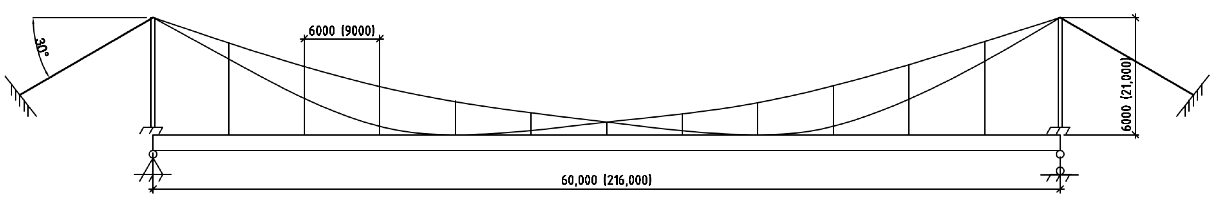
First of all, the type of bridge structure and its geometric characteristics of main elements were determined. The analysis of possible obstacles through which it is advisable to build pedestrian suspension bridges or a suspension pipeline bridge was carried out. Options for the intersection of roads and railways were considered. Analysis of the width of possible obstacles showed that it is necessary to provide a span length in the range from 60 to 220 m. At the same time, the cross-sections of the girders were chosen from two typical shapes: with a passage on the top and the bottom. Therefore, it was decided to conduct a study with two single-span suspension bridges with different types of bracing the slab to a girder. After preliminary calculations, the main dimensions of two suspension bridges were determined. The span length of the first bridge was decided to choose the minimum possible from the indicated range of lengths, namely 60 m. It was decided to choose the span length of the second bridge equal to 216 m due to the multiple number of panels of the same length.
Figure 1 shows the general layout of the suspension bridges with a length of 60 m and 216 m. For the bridge with a length of 216 m, the dimensions are shown in parentheses.
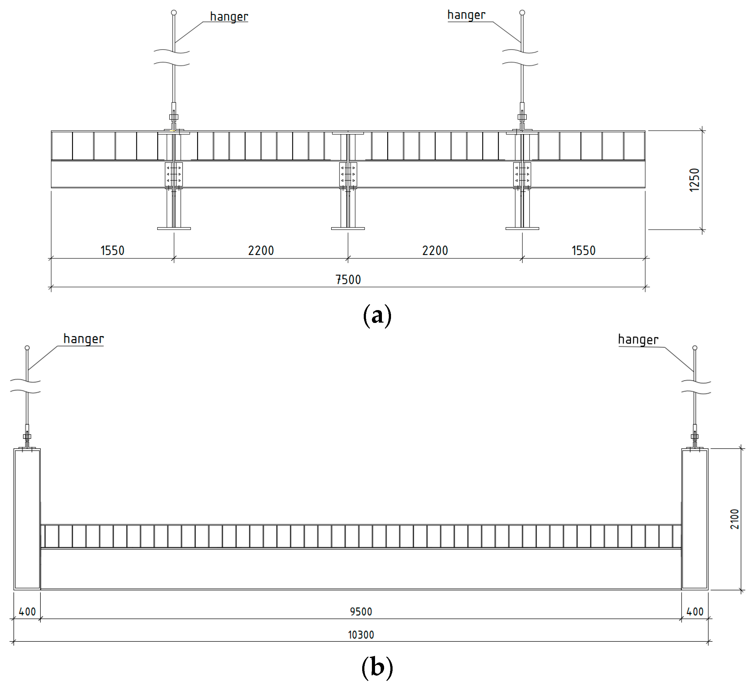
The drawings with dimensions of cross-section of girders are shown in
Figure 2. The girder with a passage on the top (
Figure 2a) was chosen for a bridge with a length of 60 m, and a girder with a passage on the bottom was chosen for a bridge with a length of 216 m (
Figure 2b).
Based on this typical shape of superstructures, the two single-span suspension hybrid bridges of 60 m and 216 m long were modeled for calculations. The girders are consisted of flat profiles; connection and joints are high-strength bolts. The pylons are consisted of an П—frame from steel beams. The two main cables of the suspension system of bridge and hangers consist of steel high-tensile-strength wires. Such a suspension system with intersection of cables was accepted for reducing the deflections of a bridge with FRP superstructure.
2.2. Numerical Calculation
The calculations of strength and flexural stiffness of pedestrian single-span suspension hybrid bridges were performed in the Midas/Civil 2019 (v2.2, build 16.04.2019) [
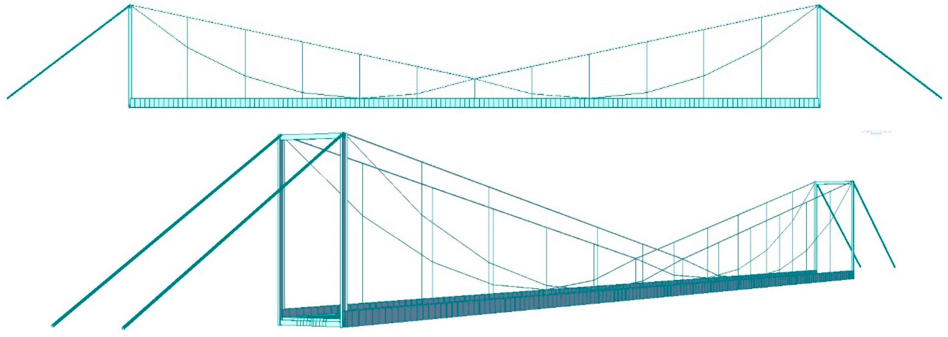
22]. This software package uses the finite-element method. The view of the finite-element model of suspension bridge is shown in
Figure 3.
The superstructure and pylons were modeled by the finite-element “beam” type. The slab was modeled of a “flat” type. The suspension system was modeled of “truss” type that works only for stretching. Girders are supported on movable and stationary pivoting bearing (along the edges of the span). The pylons and lateral bracing are completely pinched in support nodes. The piers and anchors are modeled conditionally in the form of a node with the prohibition of the corresponding movements and rotation angles.
In the finite-element model, the mechanical properties of the materials were taken into account in accordance with standards [
23,
24,
25]. For the superstructure, all profiles of pultrusion fiberglass using continuous E-glass fibers and thermosetting binder were accepted. The physical and mechanical characteristics of the material SPPS-340 type was confirmed by the standard STO 39790001.03-2007 [
24]. At the same time, according to the conclusion on this material issued in Russia by the Federal Autonomous Institution “Federal Center of regulatory, standardization and technical conformity assessment in construction”, the operating temperature range for a structure made of this material is from +80 °C to −60 °C [
25]. Therefore, this material is suitable for the construction of bridges and pipeline bridges in the Far North for the development of both civil infrastructure and energy companies.
Fiberglass was modeled as an orthotropic material. The modulus of elasticity in longitudinal direction ranges is 28 GPa, in transversal direction—8.5 GPa. The characteristic tensile strength along the grain is 340 MPa, the same in transversal direction—50 MPa. The characteristic compressive strength perpendicular to grain is 280 MPa, the same in transversal direction—100 MPa.
The design load is pedestrian—4 kPa/m2, which significantly exceeds the load from the gas pipeline or single three-axle dump truck. The dead loads were taken into account in accordance with the density and geometry of an element’s cross-section.
The suspension hybrid bridge is a fairly flexible structure, so the values of its internal forces depend on the deformed scheme of the structure. The calculation according to the deformed scheme was implemented using the function of geometrically nonlinear calculation, which iteratively recalculates the forces until the convergence of the force and displacement criteria—0.001.
Since it is impossible to combine the geometrically nonlinear calculation with the calculation of the position of live loads in the Midas/Civil, the pedestrian load was modeled by an equivalent static one in the form of a pressure on the plate elements.
The pretension of cables in a geometrically nonlinear calculation was carried out through the function of assigning a smaller value to the physical length of the cable element than the geometric distance between the two nodes.
The numerical calculation of the aerodynamics of the bridge girder is performed on a system of unsteady Reynolds—averaged Navier-Stokes equations. A geometrically similar object of the considered design was created in three-dimensional space. Preliminary studies had shown that the most suitable turbulence model for solving this problem is k-ω SST (shear stress transport). This model is a combination of two models: k-ε and k-ω, where k is turbulent energy, ε is turbulent dissipation, and ω is specific turbulent dissipation.
It should be noted, that in the study of aerodynamic stability, the girder with a passage on the bottom of the different types of the permeability of girder walls were used. The permeability of the walls is determined by the ratio (k) of the wall area minus hollows to the total area wall. It wase used in three types of the girders’ walls: a solid wall, a wall with low permeability k = 0.95 (low size of holes) and a wall with high permeability k = 0.82 (high size of holes).
For comparison with the results of previous aerodynamic experiments, as well as for a preliminary assessment of the effect permeability of the walls of girders on the values of the oscillation amplitudes, selective numerical calculations were performed. Since, according to the research results obtained earlier [
21], low values of wind resonance (in the operational range) were detected in the model of a superstructure with a passage on the bottom. Therefore, numerical calculations were carried out with this type of model in the ANSYS Fluent (v.18.0).
The three-dimensional models of the bridge superstructure with a passage on the bottom was investigated (cross-sectional height H = 0.07 m, relative width B/H = 4.9) which were models with solid (model No. 1) and the most permeable (model No. 2) walls. Calculations were carried out with the parameters of the incoming flow: velocity V∞ = 15 m/s, turbulence intensity 5%. The Reynolds number was Re = V∞ H/n = 0.72 × 10⁵. The results of the calculations clarified the flow pattern and confirmed the frequency of the descent of the vortex shroud from the superstructure.
2.3. Physical Experiment
2.3.1. The Wind Tunnel
A physical experiment was conducted to determine the aerodynamic characteristics of cross-sections, to study the dependence of the nature and amplitudes of aeroelastic vibrations on the flow velocity, as well as to find effective ways to suppress them.
Sectional models of suspension hybrid bridge spans were created on a scale of 1:30. The scale of the simulation was chosen such that the degree of filling of the cross-section of the wind tunnel was smaller than the working part of the wind tunnel area at the installation site of the model.
For this study, the wind tunnel T-503 was used, which is located in the Laboratory of Industrial Aerodynamics of the Novosibirsk State Technical University.
During the study of the models in the wind tunnel, the following types of devices were used:
- -
devices measuring the parameters of the air flow (speed, pressure, density, temperature and humidity);
- -
devices for monitoring and controlling the operating modes of the wind tunnel;
- -
instruments for determining aerodynamic forces;
- -
α-mechanism for changing the angle of attack.
The information-measuring complex maintains the constancy of the flow velocity in the working part of the wind tunnel. The accuracy of maintaining the flow velocity in the working part of the wind tunnel is not less than 0.3 m/s.
Control of the installation, collection and preliminary processing of experimental data from the thermoanemometer and strain gauges was provided in real-time using a computer-based information and measurement complex and an analog-to-digital converter unit.
The undisturbed flow velocity was determined by taking into account the field coefficient by the difference between the total pressure at the nozzle section and the atmospheric pressure measured by the pressure sensor and the control pressure gauge.
2.3.2. Types of Experiments
The following types of experiments were carried out on sectional models in the wind tunnel:
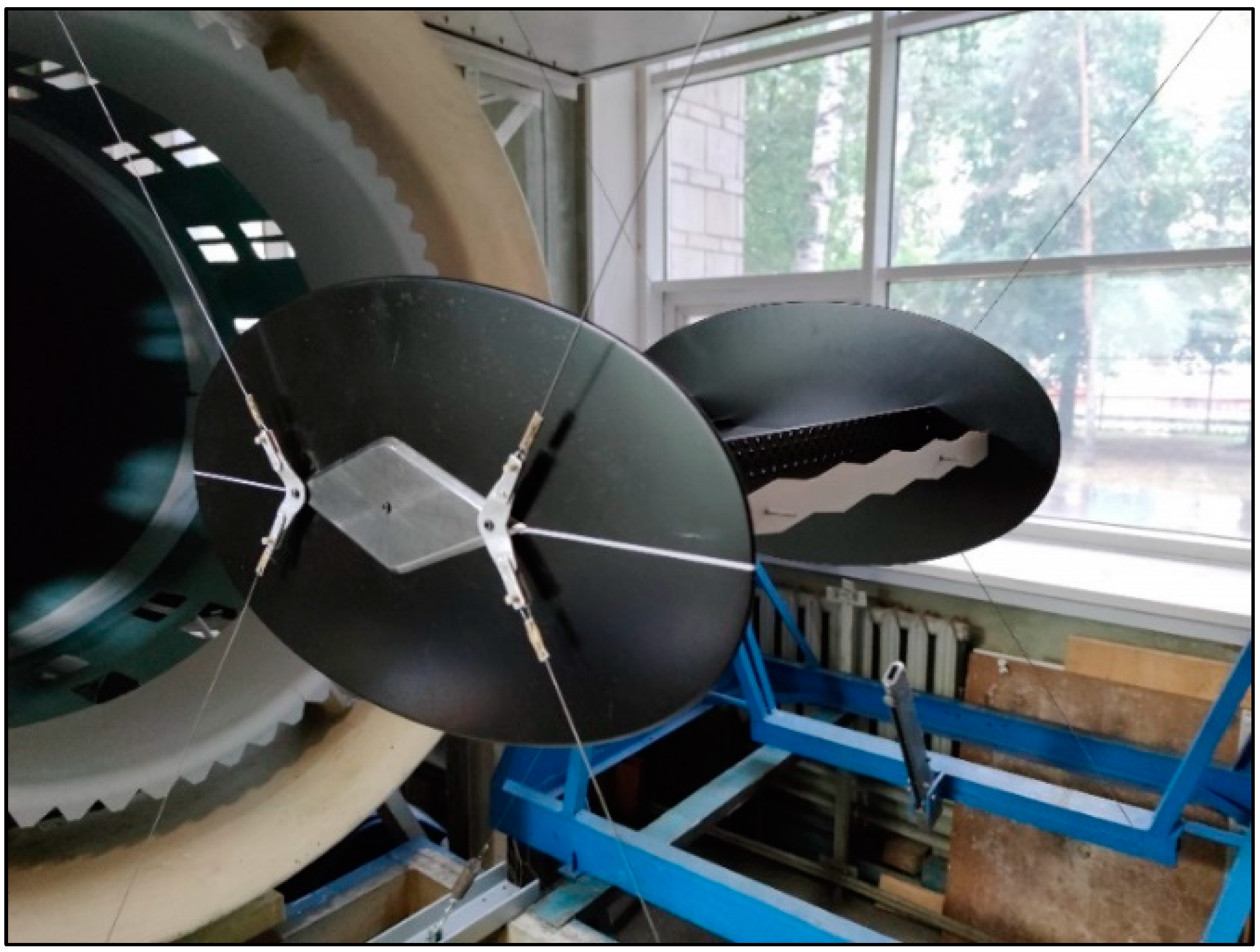
(1) Strain-gauges tests. For these types of tests, the strain gauges were used to determine the time-averaged integral aerodynamic loads acting on the sectional model at different angles of attack (
Figure 4).
During the strain-gauges tests of the models, the speed range was chosen from 4 to 22 m/s, and the range of angles of attack from −8° to +8°. The angles were changed manually in increments of 2°. The positive angle of attack is the direction of descending flow to the lower surface of the model, and the negative angle of attack is the direction of ascending flow. The coefficients of aerodynamic forces are determined by Equations (1)–(3):
where
X,
Y and
—the longitudinal and normal (relative to the flow) projections, as well as the longitudinal moment of the aerodynamic force in the associated coordinate system (averaged or pulsation components of the forces), respectively;
—the velocity head of the undisturbed flow;
S—the area of the model in the plan.
During the final processing of the results of the strain-gauge tests, corrections were taken into account. The following corrections were introduced into the calculation of dimensionless coefficients to increase the reliability of the results: (1) amendment for the mutual influence of the components of the strain-gauges balances; (2) the influence of the projections the weight of the model and the weight of the strain-gauges balances when the angle of attack changes; (3) amendment on the deviation of the initial wind flow; (4) the influence of the deformation of the rack and elastic elements of the strain-gauges balances; (5) amendment on the cluttering of the working part of the wind tunnel with the model and the satellite jet; (6) amendment on the finite elongation of the section model and the influence of the end disks.
(2) Thermoanemometric tests were performed to determine the prevailing frequency of velocity pulsations and calculate the Struhal number (
Figure 5).
A one-thread thermoanemometer was used as a probe for measuring the pulsations of the flow velocity in the near-model space. The wind tunnel is equipped with a coordinate device that allows to move the measuring probe almost over the entire volume of the working part, as well as with the ability to change the heading angle of the probe. The accuracy of movement along the longitudinal and transverse axes is 1 mm, along the vertical axis—0.5 mm and along the angle—0.5°.
To carry out thermoanemometric tests, the model was laterally attached to rigid racks to reduce the effect of vibrations on the frequency of vortex descent. Thermoanemometric tests were carried out by measuring velocity pulsations in the near models using a constant resistance thermoanemometric complex, in which the sensor moves longitudinally and transversally relative to the flow using a coordinate device.
All recorded electrical signals from the sensor were converted into digital form and recorded in data files. The obtained data was processed by Fourier analysis, which allows to find the prevailing frequencies of velocity pulsations and to calculate the Struhal. Studies of the near-field of the models using a thermoanemometer were carried out at an average velocity of the incoming flow V∞ = 16 m/s.
(3) Determination of the dependences of the amplitude of steady-state oscillations on the velocity of the incoming flow.
The purpose of experiments on sectional models suspended on elastic suspensions is to determine the characteristics of the relative amplitude of oscillations (A/H) on the reduced velocity (V/fH). Here, A/H is the ratio of amplitudes to girder height, V/fH is the ratio of the velocity to frequency and girder height.
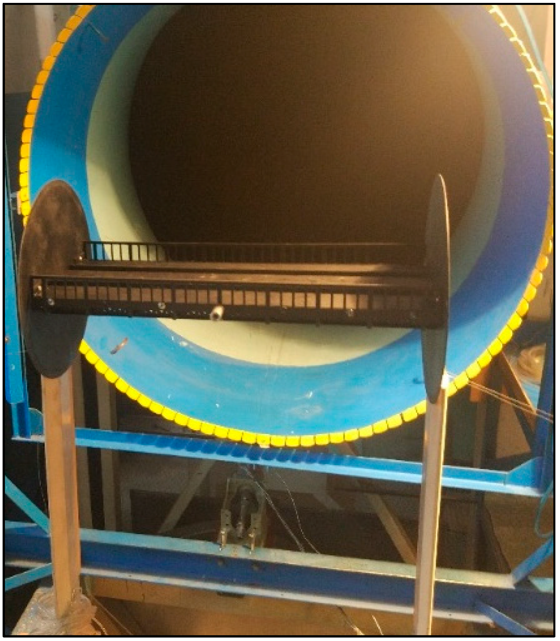
The dependences of amplitude oscillations of bridge superstructures on sectional models on the velocity of the incoming flow were determined. They were suspended in the working part of the wind tunnel on eight elastic suspensions for various shapes of oscillations (see
Figure 6).
Measuring strain gauges were installed at the ends of the suspensions to register the amplitudes of oscillation. On each elastic suspension was installed three strain gauges. They were appropriately connected into three full-bridge circuits on both sides of the model and provided separation of the components of the transmitted force and torque. The measuring equipment provides from 50 to 100 samples per oscillation period.
The flow rate varies discretely from zero to maximum in increments of 1–2 m/s. At each speed value, after a period of time (from a few seconds to 1–2 min), a certain stationary oscillation amplitude was established, the magnitude of which can reach the order of 10 mm. The intensity of the oscillations was recorded by the information-measuring complex and was displayed on the display in real-time.
2.3.3. Similarity Criteria
To be able to transfer the results of experimental studies of the model to a full-scale structure, it is necessary to comply with the requirements of the criteria of similarity theory. The model and the full-scale object must be geometrically similar, equally located in space relative to the flow, and the flows themselves must be kinematically and dynamically similar [
26].
Dynamic similarity is due to the observance of geometric and kinematic. For this similarity, it is necessary to ensure the same application of forces to elementary volumes located at similar points of the flow, as well as the same ratio of these forces. Usually, partial compliance with the requirements of these criteria is sufficient due to the presence of self-similarity of the flow [
26,
27].
However, it is sufficient to provide partial dynamic similarity according to the defining criterion. For the average values of aerodynamic forces in a steady flow, the defining criterion of similarity is the Reynolds number. This is necessary to ensure equality between the forces of viscosity of the flow and inertia using the Equation (4) [
26]:
where the indices
m,
n denote the model and full-scale object;
V—the speed of the wind flow;
H—a characteristic size of the object; ν—the kinematic viscosity of air.
Analysis of Expression (4) shows that this ratio will differ mainly by the magnitude of the scale, since the flow rate can be set, and the air viscosity varies in a narrow range of values. Therefore, this condition is fulfilled on the basis of the existence of self-similar flow of poorly streamlined bodies in the range of Reynolds numbers from 104 to 107. This is due to the fact that the flow disruption occurs from the sharp edges of the model elements and the nature of the flow does not depend much on the Reynolds number. Thus, achieving complete equality of model and full-scale Reynolds numbers is not required.
However, there is a need to conduct an experiment in the specified range of Reynolds numbers which makes it possible to neglect the surface roughness due to the self-similarity condition.
For the study of oscillatory or periodically recurring processes in the flow (for example, in a thermoanemometric study), a similarity criterion was provided. The periodicity of the occurring phenomena takes into account the Struhal number according to the Equation (5) [
26]:
where
f is the characteristic frequency of the vortex descent.
Moreover, it is necessary to determine the effect of the height of the superstructure above the underlying surface on the aerodynamic characteristics [
28]. The distribution of wind speed in height has a law close to an exponential function. However, it was found that the change in the flow velocity along the height of the superstructure model is relatively small when Equation (6) will be fulfilled. Therefore, it is permissible to use a constant velocity along the height of the model in experiments:
where
H—the height of the superstructure to the ground;
hs—the height of the superstructure.
3. Results
3.1. Previous Studies
Based on the results of numerical calculations of suspension hybrid bridges with a fiberglass superstructure, the following hypothesis was put forward. The stiffness of FRP girders with a small modulus of elasticity can be secured if there was an increase in the moment of inertia of the cross-section girders and the use of a suspension system of increased stiffness, while providing aerodynamic stability. In this way, the FRP will be adapted to the requirements of design standards.
As a result of calculations, it is confirmed that using a suspension system with increased stiffness and fiberglass girders with the required moment of inertia, it is possible not only to meet all the requirements of regulatory documents, but also to eliminate the S-shaped bending of the girder due to the absence of the “thread” effect during deformation of the suspension system [
17,
18]. The “thread” effect means that with an asymmetrical arrangement of the live load on the superstructure, the second part of the span will be bent upwards.
However, an there is an increase the moment of inertia, primarily, due to an increase in the height of the FRP girders. This inevitably leads to an increase in the force of aerodynamic impact. Besides that, the structures considered in the study have a reduced mass relative to the use of conventionally used materials and an increased frontal area. At the same time, the change of aerodynamic characteristics depends on the ratio of geometric parameters and the shape of structural elements. To substantiate the possibility of ensuring the aerodynamic stability of a suspension hybrid bridge in accordance with the requirements of the Russian standard by paragraph 6.24 of SP 35.13330.2011 [
23], it was necessary to conduct the special studies in a wind tunnel.
As a result, tests of sectional models of the bridge on the strain-gauges balances allowed us to identify variants that were not prone to galloping, divergence and vortex resonance. At the same time, the most effective vibration damping devices were identified, the use of which reduced the energy of pulsations in the trace by up to 70%. However, tests of a sectional model of a superstructure with a passage on the bottom had shown that without vibration dampeners, all variants of the model are susceptible to wind resonance in the wind speed range of 8–20 m/s and a stall flutter with a wind of more than 20 m/s [
19,
20,
21]. Therefore, tests of the same sectional models with a passage on the bottom, but hanged on elastic suspensions, were carried out. According to the test results, it was to determine the values of the oscillation amplitudes, and the most effective additional vibration damping devices were found.
3.2. Numerical Aerodynamic Calculations of Sectional Models of Superstructures with a Passage on the Bottom
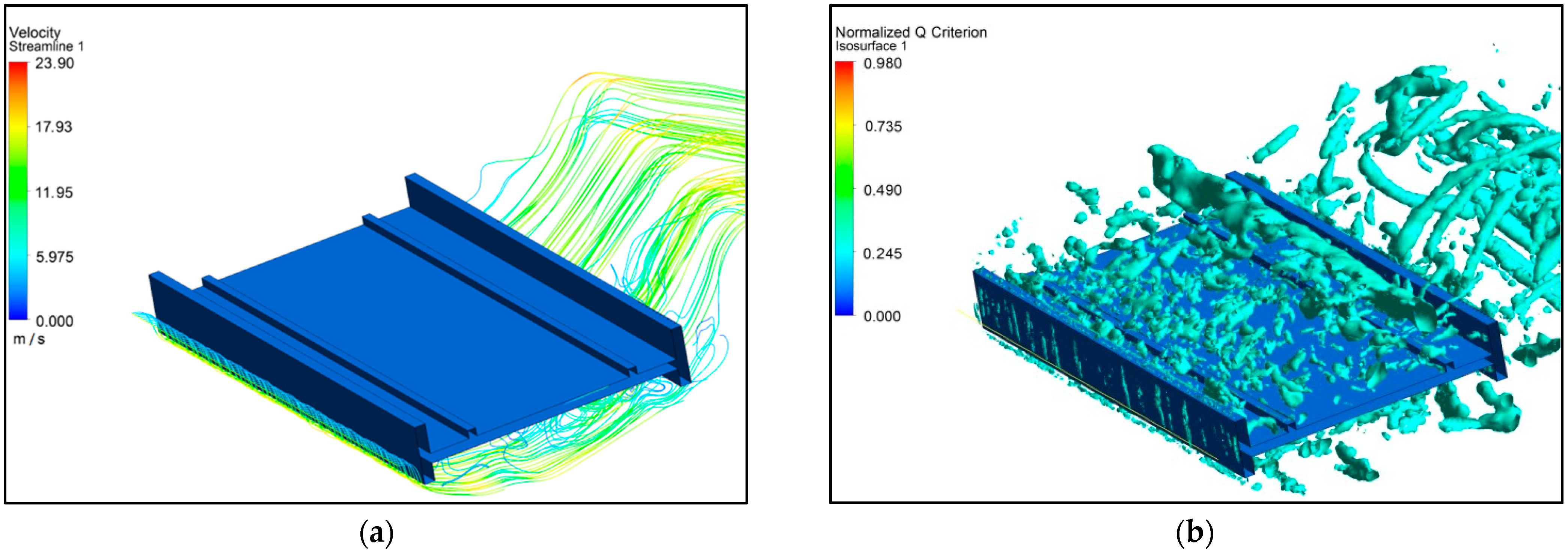
The results of numerical calculations of the flow around the superstructure model with solid walls are presented in
Figure 7.
As can be seen from
Figure 7a, the presence of impenetrable vertical walls in the section leads to the appearance of extended tear-off bubbles near the upper and lower surfaces of the girder.
Figure 7b shows a three-dimensional vortex shroud descending from the surface of model No. 1 from the surface of the superstructure model. The pulsating component of the lifting force is characterized by a coefficient
= 1.343.
Thus, the calculations of the aerodynamic characteristic of a span structure model with solid walls in a three-dimensional measurement confirm the propensity of this superstructure to vortex excitation of vibrations.
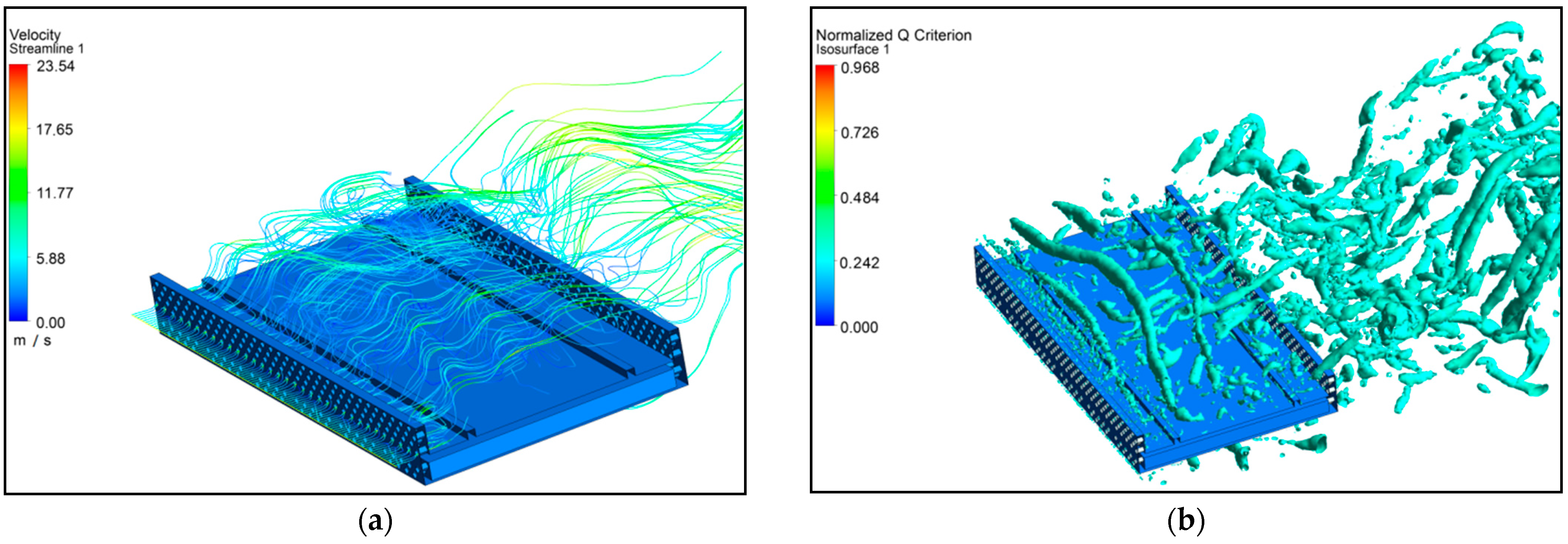
The results of calculations of the flow around model No. 2 of girder with permeable walls are presented in
Figure 8.
As can be seen from
Figure 8a, the permeability of the walls leads to a decrease in the vertical extent of the tear-off bubbles and their fragmentation. At the same time, a zone of synchronized vortex shroud vanishing occurs near the front wall (the “tubular” shape of the fragments of the isosurface of the Q-criterion) and are presented in
Figure 8b. Thus, the presence of holes leads to a quasi-two-dimensional flow around the front wall.
The pulsating component of the lifting force is characterized by a coefficient 0.434, i.e., it is reduced by 3 times compared to the model with a solid wall.
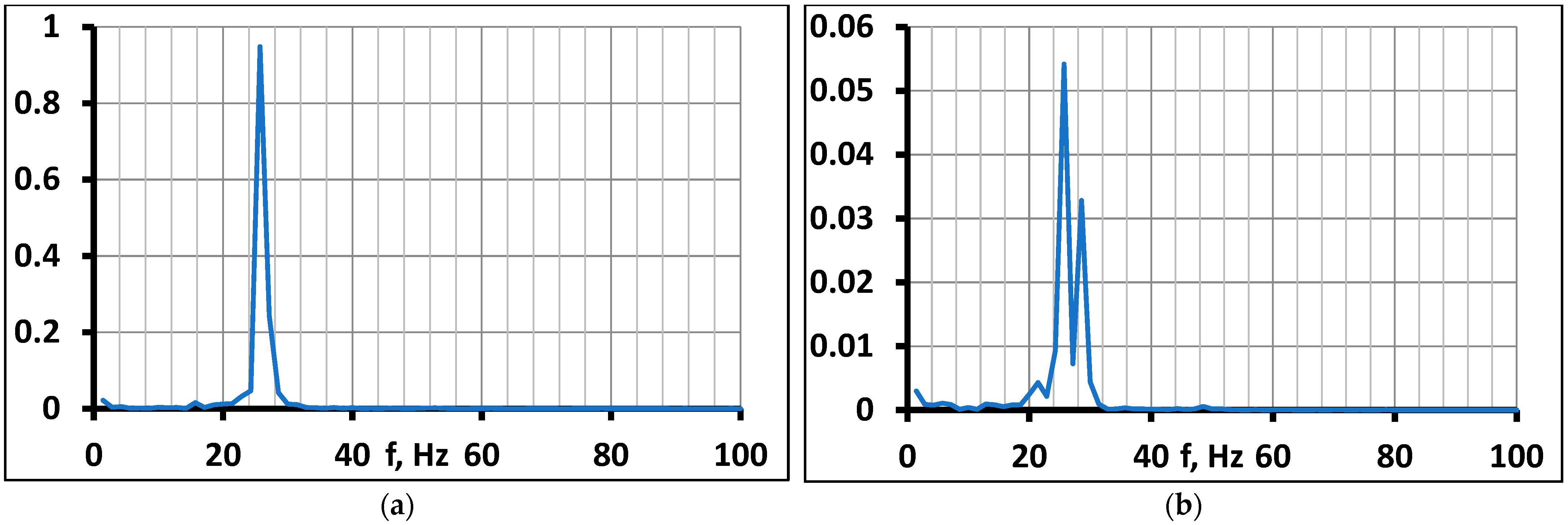
The result of spectral analysis of lift pulsations for the zero angle of attack for both models in numerical environment is shown in
Figure 9. The dominant frequency f
a = 25.7 Hz was revealed for both models of girders (with solid walls and permeable). This frequency corresponds to the Struhal number Sh = 0.112.
At the same time, these parameters were previously determined for the same models in the wind tunnel and by the numerical calculation method in a two-dimension. These values for model with solid walls were determined by physical experiment as an equal f
a = 26.6 Hz and Sh = 0.116 [
21]. Also, these values for model with solid walls were determined in numerical environment as an equal f
a = 25.1 Hz and Sh = 0.111 [
21]. For model with permeable walls values were determined by physical experiment as an equal f
a = 25.7 Hz and Sh = 0.112 [
21]. Thus, the values obtained by different methods are close to each other and confirm the reliability of the results.
Thus, by the numerical calculation in a three-dimensional measurement revealed the influence of perforation of the girder walls on the flow pattern and aerodynamic characteristics of the model, which is associated with the formation of a quasi-two-dimensional flow region behind the front wall. At the same time, according to calculations, the pulsation component of the lifting force decreases by 3 times, and the frequency of the descent of vortices from the superstructure model remains unchanged.
3.3. Investigation of the Forms of Aeroelastic Vibrations of the Initial Configurations of Flight Structure Models
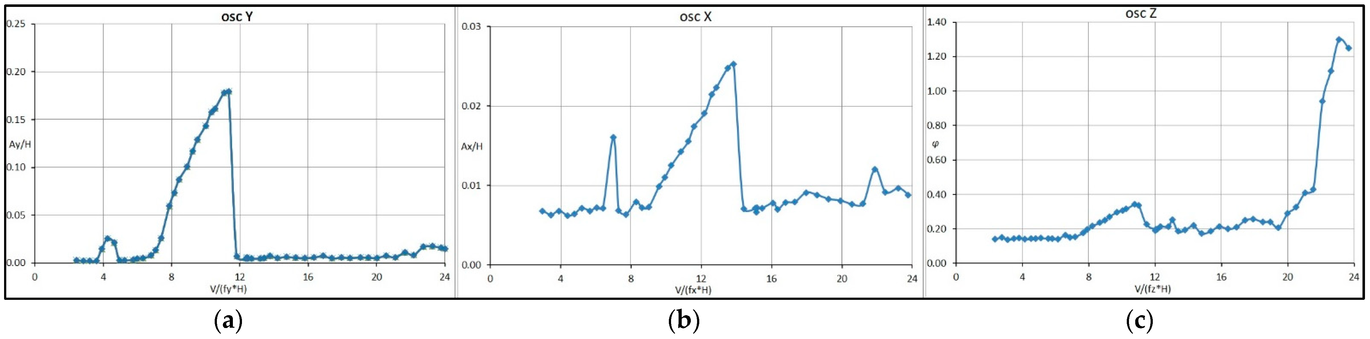
Figure 10 shows graphs displaying the amplitude of oscillations (A/H) on the reduced velocity (V/fH) of superstructure with solid walls’ girders. The logarithmic decrements of the oscillations in the experiments was accepted as an equal δ~0.015.
Experiments had shown that the initial configuration of the superstructure model is prone to the excitation of aeroelastic vibrations in several forms. The most intense vibrations occur at the following frequencies. In the horizontal plane, the frequency is equal fx = 10.8 Hz; in the vertical plane, the frequency—fy = 10.1 Hz and torsional vibrations around the lateral axis, the frequency—fz = 13.5 Hz. This corresponds to the lowest vibration frequencies of the full-scale superstructure: 0.583 Hz in the horizontal plane, 0.745 Hz in the vertical plane and 1.025 Hz torsional around the longitudinal axis of the superstructure.
Vibrations in the horizontal and vertical planes are characterized by the presence of two speed ranges, in which their amplitudes sharply increase. At the same time, for oscillations along the x axis, the first, less intense peak falls on the reduced velocity V/f
xH~7. At speeds V/f
xH~9–14, there is a gradual increase in the amplitude of the oscillations A
x/H 0.007 to 0.026, after which the oscillations practically stop (see
Figure 10a). Oscillations in the vertical plane have a similar character. In the first velocity range corresponding to V/f
yH~5–6, oscillations with moderate amplitudes reaching A
y/H~0.025 are observed. The second range begins with V/f
yH~9 and continues to V/f
yH~14, while very large amplitudes of A
y/H~0.18 are achieved. After that, these oscillations in this form are stopped (see
Figure 10b).
In general, the nature of vibrations in the horizontal and vertical planes gives grounds to attribute them to wind resonance.
Torsional vibrations relative to the z axis also occur with different intensity at different speeds. In the range V/f
zH~ 7–11, the amplitudes increase from 0.16 to 0.35 degrees, after which the oscillations weaken approximately to the initial state. In the region of high speeds, starting from V/f
zH~20, there is a sharp increase in amplitudes by almost an order of magnitude, as they reached 8 degrees with a tendency to increase (see
Figure 10c). A further increase in speed could lead to the destruction of the model or elastic suspension, so it was decided not to exceed this level.
The nature of torsional oscillations relative to the z axis shows that this is a stall flutter. As it is known from the practice of research on the aerodynamic stability [
29,
30], the special vibration damping devices and permeability are used to reduce the oscillation amplitudes of the stall (torsional) flutter. Therefore, the following tests in wind tunnel were carried out.
3.4. Investigation of the Influence of the Girders’ Walls Permeability on the Parameters of Aeroelastic Vibrations
It should be noted that all forms of vibrations described above, to a greater or lesser extent, take place for all the considered variants of models of superstructures in the initial configurations, which differ in the permeability of the girders’ walls. However, for a more compact presentation, the results will be given below mainly for vibrations in the vertical plane (along the y axis), as the most intense and therefore, representing the greatest danger damage of construction.
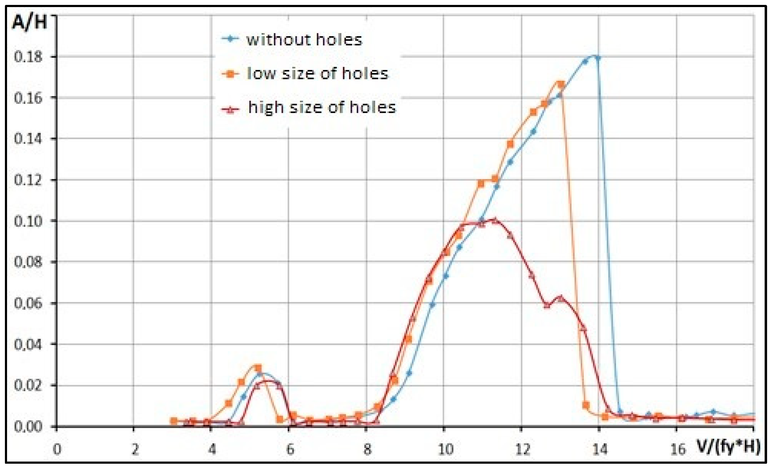
Figure 11 shows the results the effect on the amplitude of oscillations (A/H) of initial configuration sectional models of the superstructure in the wind tunnel. Three models differ by the permeability of the girders’ walls: a solid wall, a wall with low permeability (low size of holes) and a wall with high permeability (high size of holes).
As can be seen from
Figure 11, for all three variants of graphs there are two ranges of relative velocities (V/fH) in which aeroelastic oscillations occur. In the first range corresponding to V/fH~5–6, fluctuations with moderate amplitudes reaching A/H from 0.02 to 0.03 are observed. The second speed range starts at V/fH~8 and continues to V/fH~14; it corresponds to much more intense oscillations. For models with solid walls and walls with small perforation, the oscillation parameters do not differ much, their maximum amplitudes reaches 0.17–0.18 at speeds V/fH~13–14. After this range, the oscillation intensity dropped sharply to almost zero.
An increase in the perforation of the walls has a significant effect on the intensity of aeroelastic vibrations. For a model having walls with high permeability, the maximum amplitudes are almost two times smaller (A/H~0.1) than for models with solid walls and walls with small perforation. In addition, it should be noted that in this case, the maximum amplitudes are found at lower speeds (V/fH~11). As the speed increased further, the oscillation amplitude decreased gradually and approached zero at approximately the same speeds as for models with solid and low-permeable walls (V/fH~14).
Thus, even the use of the maximum permissible perforation of the girders’ walls in terms of structural parameters does not effectively reduce the intensity of aeroelastic vibrations of the superstructure in the vertical plane, as well as torsional vibrations around the longitudinal axis.
In terms of full-scale wind speeds at the level of the superstructure, the dangerous ranges are: for oscillations in the vertical plane 11–19 m/s, for torsional, more than 41 m/s. Therefore, fluctuations in the vertical plane are quite likely, and the range of dangerous torsional vibrations is located in the region of very high wind speeds, unattainable for all wind areas. Nevertheless, it is possible to reduce the magnitude of the oscillation amplitudes, and hence the intensity of the aerodynamic impact, through the use of additional devices.
3.5. Results of Experiments on Sectional Models with Vibration Damping Devices
To reduce the oscillation amplitudes, additional tests in the wind tunnel were carried out on models with devices that reduce the forces of aerodynamic impact. Therefore, the additional wind tunnel tests were carried out on models with devices that reduce the forces of aerodynamic impact. Since among the results of previous studies, a significant decrease in the intensity of vibrations was detected in models with the largest holes in the girder walls compared to other models, then these models were adopted for comparison with models with solid walls to study the effectiveness of vibration reduction devices.
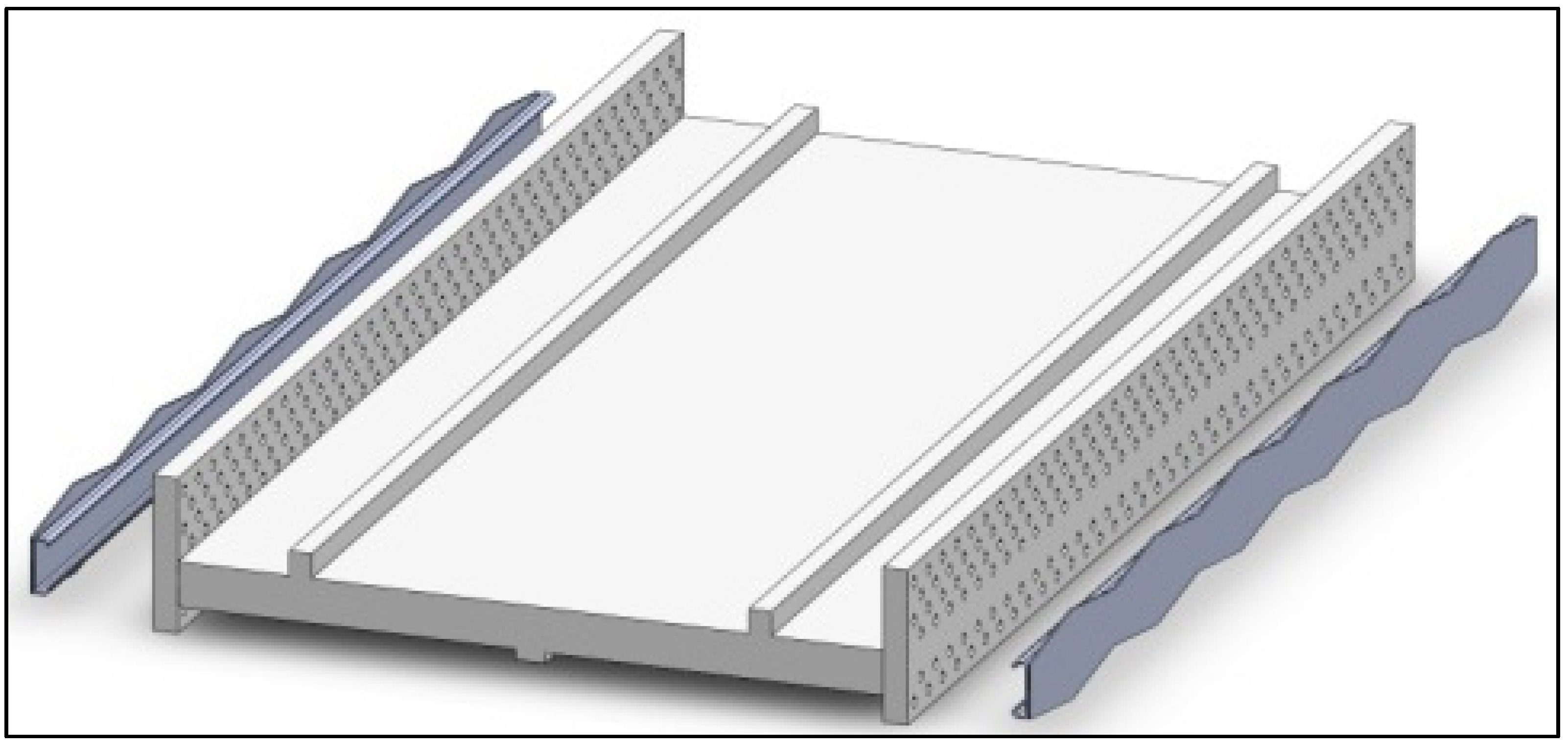
In total, more than 50 types of various devices for damping oscillations were studied. The devices of forward-facing shields showed the highest efficiency (
Figure 12).
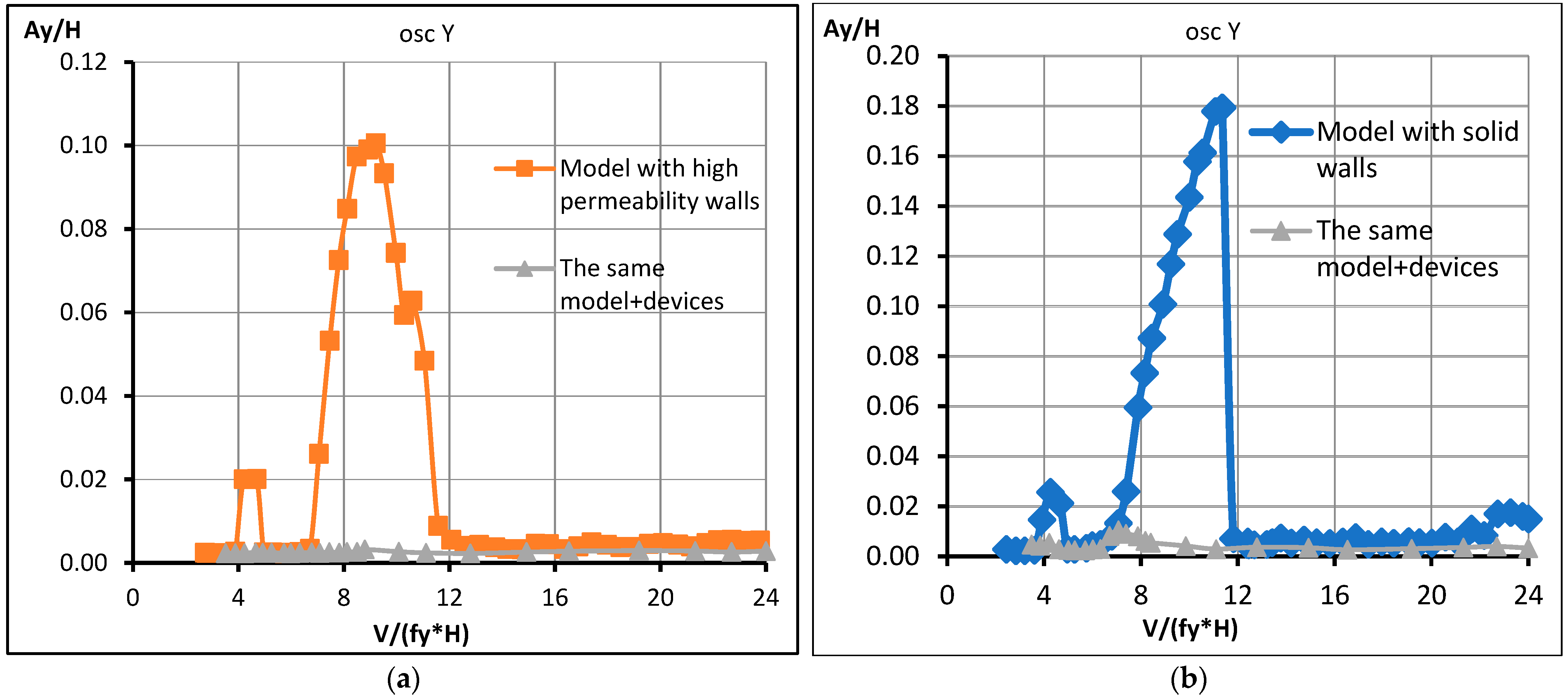
The forward-facing shields have shown their high efficiency. The relative amplitude of models with both solid walls (
Figure 13a) and perforated ones (
Figure 13b) do not exceed 0.003–0.004, which is approximately 30–40 times less than for the initial configurations without devices.
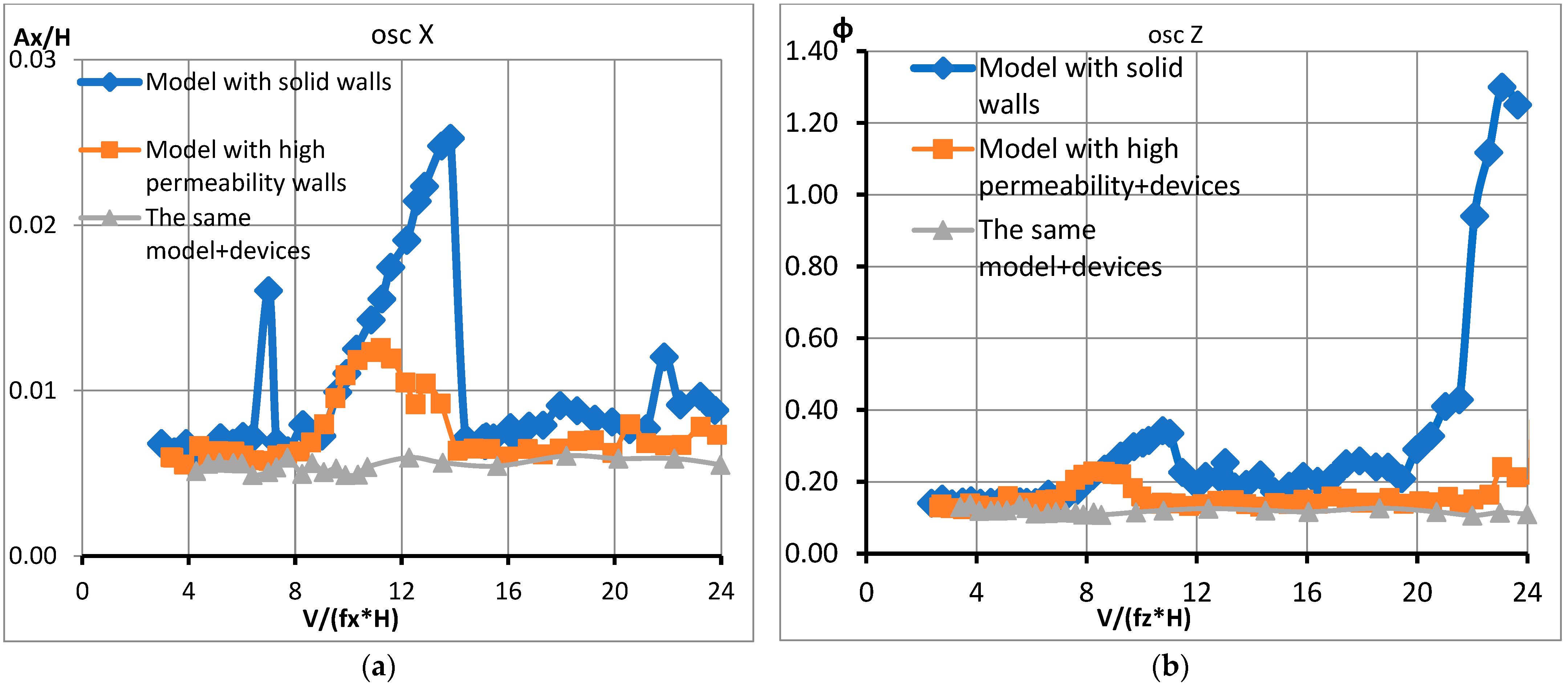
All tested versions of the devices were controlled from the point of view of reducing the intensity of vibrations of other forms—in the horizontal plane and torsional. As an example, we give the corresponding characteristics for the device No. 1 from
Figure 14a,b. As can be seen from the graphs, in the studied speed range, the oscillation amplitudes of models with devices have slightly decreased compared to models without devices, and do not exceed A/H~0.005–0.006 and ϕ~0.1–0.12 degrees.
4. Conclusions and Discussion
At the beginning of the study, the following hypothesis was put forward. The stiffness of FRP girders with a small modulus of elasticity can be secured with an increase in the moment of inertia of the cross-section girders and the use of a suspension system of increased stiffness, while providing aerodynamic stability. In that way, the FRP will be adapted to the requirements of design standards. The results of the study showed that this hypothesis was confirmed: the deflections of the bridge were limited, and the strength of the load-bearing elements was bleached. However, since the study was carried out with suspension bridges, it was necessary to investigate the aerodynamic stability of these structures. The study showed that the structures are resistant to many types of aeroelastic instability, except for the stall flutter for the bridge with the second type of beam. To do this, an additional study was conducted with vibration damping devices. As a result, aerodynamic stability was confirmed for all models.
As a result of the whole research study, the following tasks were solved:
Numerical geometrically nonlinear computational models of pedestrian suspension hybrid bridges made of fiberglass have been studied with the use of constructive solutions that effectively use the advantages of the material and reduce the impact of its disadvantages.
The aerodynamic characteristics of the proposed cross-sections of the suspension hybrid bridge spans have been experimentally determined.
The novelty of solving the first and second tasks is concluded in the following. Based on the results of numerical calculation, additions to the structural solution of the suspension system and the FRP girders of hybrid pedestrian suspension bridges were proposed. Namely, in order to apply FRP girders in pedestrian suspension bridges, it is necessary to use a suspensions system with increased stiffness (with additional elements), as well as to determine the geometric of the girders from the condition of limiting deflections, while this strength is ensured [
17,
18].
The acceptable parameters for assigning the dimensions of the two cross-sections of the suspension hybrid bridge span have been experimentally established. The aerodynamic characteristics of the cross-sections of fiberglass superstructures of a suspension bridge were obtained for the first time. Experimental results have confirmed the possibility of ensuring the aerodynamic stability of these structures in general [
19,
20,
21]. Despite the fact that the second cross-section is also resistant to the phenomenon of galloping and divergence, it has low values of the critical velocity of the wind resonance [
21].
Therefore, this study described in this article was devoted to the search for means of damping the oscillation amplitudes of the second-section model. The study allowed us to obtain the following results:
- -
the intensity of aeroelastic vibrations of the superstructure model depends on the permeability of the girder walls. With the greatest (in terms of design possibilities) permeability, the maximum oscillation amplitudes decrease by almost 2 times compared to the model with solid walls.
- -
to further reduce the amplitudes of aeroelastic vibrations, the most effective damping devices out of 50 variants were determined. The best developed vibration damping devices reduced the amplitudes up to 30–40 times compared to the original configuration of the model with a solid wall without devices. The final choice of vibration damping devices from a number of similar aerodynamic efficiency levels should be based on the results of a feasibility study, which is beyond the scope of this study.
- -
the use of devices has significantly reduced the amplitudes of models’ oscillations in case of wind resonance and eliminated the stall flutter in the operational speed range (see
Figure 12 and
Figure 13).
Thus, variants of models with reduced oscillation amplitudes providing aerodynamic stability were determined. Note that the comparison of the values of aerodynamic drag coefficients obtained from the results of experiments with the values for various bridge structures are presented in Appendix H SP 35.13330 [
23].
Taking into account the results of the study, the conditions allowing the use of promising FRP in the superstructures of pedestrian suspension hybrid bridges with the provision of strength, rigidity and aerodynamic stability are determined.
One of the further tasks that need to be solved is the standardization of the criteria selection for the cross-sections of the girders. However, now, based on the results of this study, the following conclusions can be drawn. A comparison of two different cross-sections of superstructures with a passage on the top and the bottom showed that the only ratio of their height to span length is not enough to compare the FRP girders of suspension bridges with the girders from conventional materials.
Despite the fact that the relative height of the girder of the two types of sections differs by half (1/50 l and 1/100 l, where l is the span length), the ratio of the bending stiffness of the section to the span length differs by only 15% in favor of the section with a passage on top (1/50 l). At the same time, as follows from the results of calculations and experimental data, the required bending stiffness and aerodynamic stability were provided for both types of sections. Following criterion about production, the method of manufacturing fiberglass depends on the geometric shape of the cross-section and its aerodynamic characteristics.
Therefore, in view of the lack of extensive experience in the use of FRP, in addition to the requirements for the characteristics of materials, it is necessary to establish geometry requirements as this will increase the efficiency of the implementation of FRP.


 ,
, 