Abstract
Substations are becoming increasingly reliant on international electrotechnical commission (IEC)-61850-enabled devices. However, device compatibility with these standards does not guarantee interoperability when devices are taken from different manufacturers. If interoperability of multivendor devices can be achieved, then power utilities will be in a position to implement multivendor devices in substations. The study here presents the development and testing of a digital substation test platform that incorporates devices from different manufacturers. The process bus communication and protection operation of the intelligent electronic devices (IEDs) were tested to validate device interoperability. The testbed was tested for two IED process bus communications, generic object-oriented substation event (GOOSE) and sampled measured value (SMV). The GOOSE is travelling between IED to IED with an end-to-end (ETE) delay of 2 ms and the SMV read by the IEDs are the same as the injected real-time substation inputs 220 kV and 1 kA. Three IED protection studies (overcurrent, earth fault, and overvoltage) were performed, and IED response curves were obtained. In addition, data monitoring and client–server communications were studied using installed software tools. The testbed configuration in this study has faced some real-time challenges regarding differences in device edition, device firmware, and ethernet switch due to its multivendor approach. All the mentioned configuration issues were resolved in this study with successful testing and validation of the testbed. The study of this testbed will provide solutions to the problems associated with a multivendor system faced by substation engineers and will help them in opting for multivendor installations. This system can be extended in the future by installing more multivendor devices with complex network topology and a SCADA system.
1. Introduction
Modern power system networks are capable of better serving their customers with efficient communication networks, faster protection schemes, and future expansions as they have high-performance IEDs. Advanced IEDs require standard protocols for control, monitoring, and protection. With the evolution of the IEC 61850 standard by the International Electrotechnical Commission, the interoperability of IEDs from different vendors has become a challenge to provide more powerful substation control and protection operations [1].
The foundation of substation automation systems (SAS) was built with the IEC 61850 and Ethernet process bus network to provide high-speed data communications between primary and secondary systems [2]. The interfacing of substation secondary systems using the IEC 61850 standards has many benefits over previous hardwired interfacing models in terms of improvements in substation safety, reduction in wiring costs, lesser outage timings for commissioning and maintenance, etc. However, digital substations are facing problems in their interoperability operations and testing strategies.
The power industry is moving towards smart grids due to the addition of distributed energy resources (DERs) for localized power generation and to meet the increasing load demands. With the smart grid approach, the need for long-distance transmission and challenges associated with it can be reduced. A smart grid architecture involves computer control technologies and advanced communication networks to facilitate automated operations and controlling of power grids. There are various studies performed by the authors on smart grids and their various aspects.
The authors in [3] discussed the challenges in today’s distribution networks and the features of using smart grids in connection with distributed generations. A real-time project and implementation methods in this area were discussed by the authors. A simulation method with both RTDS and dSPACE environment for modelling of smart grids with DER integration was proposed by the authors, which will help in designing and testing a smart grid in a simulation environment before the installation of an actual grid. The authors also proposed the use of an automated meter reading system for network management and power quality monitoring.
Similarly, a smart grid model was proposed by the authors in [4] that covers all grid level generation, transmission, sub-transmission, and distribution systems in its architecture. As computer-controlled technologies are involved in a smart grid, a smart grid will have a huge amount of data to process and store, which is imposing a challenge in its implementation. To address this issue, the authors proposed a hybrid cloud-based smart grid in their study for processing such big data. The hybrid cloud proposed in the study has a private cloud framework that will develop a wireless sensor network for monitoring the grid to enhance the grid performance.
The studies in smart grids will help in developing new efficient systems and also upgrade the existing grids into more efficient smart grids with automated operations. There are many other studies ongoing in this area, and the systems will be upgraded in the future. The smart grid architecture will be more efficient while having automated substation operations, which can be achieved by the installation of digital substations at the distribution end and also an integration of DERs in its architecture.
The digital substation model secondary systems are digitalized by replacing all copper wire communications with fiber optic (FO) cables. There are analog merging units (AMUs) placed at the primary plant secondary terminals of the substation for IED process bus communications using GOOSE [5] and SMV [6,7]. IEC 61850 protocols used to facilitate IED interoperability are IEC 61850-8-1 for GOOSE and IEC 61850-9-2 for SMV communications.
Digital substation secondary systems are also enabled with the plug-and-play approach to benefit the substation’s present and future operations, future expansions, and cost [8]. Substation interoperability testing is generally performed by individual manufacturers of their products. In this scenario, the coordination of device operations and data security will not be a problem. In the testing of devices from multiple manufacturers, it can be seen that either the testing is not fully evaluated or that they are facing problems [9].
Interoperability operations with IEDs and AMUs from different vendors often face problems because each vendor does not interpret the standards identically. Many studies have tested model interoperability using simulation software platforms. IEC-61850-based substation communications using software platforms with python coding [10], optimized network engineering tools (OPNET) simulation software [11], Victoria university zone substation (VUZS) simulator [12], and virtual IEDs using MATLAB [13] represent certain simulation result analyses of digital substations.
A distance protection relay was simulated in MATLAB and tested for IEC 61850 GOOSE and SMV communications in the HYPERSIM modulator in [14]. In addition, SAS prototype testing [15] and cyber security testing [16] of communication networks were conducted in simulated testbeds. However, in hardware prototypes, the commercial devices may behave differently than in a simulation platform, and their interoperability operations still face many challenges that need to be addressed.
In some papers, the authors developed a laboratory prototype testbed to validate their simulated models. The IEC 61850 communication network SMV messaging with IEC 61850-9-2 and GOOSE message transfer with its ETE delay have been studied using prototype testbed setups that have only single vendor devices [17,18]. To test the voltage and current sampled values, a grid fault was simulated using MATLAB software, and the author used a single vendor laboratory testbed to validate the results in [19]. There are many other research papers on testing GOOSE and SMV communications with hardware validations, but all have used single vendor-specific devices [20,21,22,23].
A literature study of the above papers on IEC 61850 substations shows that most of the authors attempted to design IEC-based substations using various simulation platforms or single vendor devices. They tested their models to establish the interoperability of devices, process bus communications: GOOSE, SMV, and protection operations. In a simulation model, larger networks can be developed but their output depends on the quality of the simulation work performed. The commercial Ethernet switches, IEDs, AMUs, testing tools, or any other substation device’s real-time operative results may differ significantly from the simulation results. However, laboratory testbeds with multivendor devices will impose more challenges in their installation and interoperability than a single vendor testbed will offer.
While most of the studies in the area of IEC-61850-based substation models are either simulation-based models or single vendor prototypes, the proposed study in this paper is of a multivendor single-bay IEC-61850-based substation prototype. The limitations of a simulation-based model and a model with single vendor devices were already discussed. The laboratory testbed proposed in this study has a new approach of using multivendor devices in its architecture so that a digital substation installation and future maintenance can become cost-effective and faster.
The model was implemented and tested for interoperability operations of substation devices. During the configuration, some real-time challenges were resolved in this study that will provide some crucial information to the substation engineers about points to take care of while implementing a multivendor substation. We compared the work performed in the proposed model with the above-discussed studies, and this is summarized in Table 1.
Table 1.
Comparative analysis of the proposed study with the existing literature.
This study has contributions as explained below:
- A laboratory testbed of IEC-61850-based substation was configured and installed using multivendor devices.
- The problems that were faced during the installation are resolved with the successful testing of device interoperability.
- The substation model developed was tested for validating substation process bus communications.
- Validations of IED protection studies are performed with user-defined IED settings.
The multivendor testbed developed in this study will help substation engineers in understanding whether they can use multivendor devices in an IEC-61850-based digital substation or not and how they can install it. The configuration challenges faced in this study due to differences in the device editions, device firmware, and Ethernet port settings are discussed in this study with possible solutions. The goal of this study is to provide the basic idea of a digital substation with multivendor devices and to encourage substation engineers so that they can opt for multivendor installations in their substations, which will make the system reinstallation cheaper and faster.
The proposed testbed is a small-scale laboratory prototype having fewer substation devices, simple communication architecture, and only single-bay operations. However, before the real-time installation of an actual working substation with multivendor devices, a larger prototype with a greater number of devices and complex network topology should be tested for standard operations. The testbed developed in this study is lacking in having a SCADA system for controlling different levels of the substation operations from a central control center or remote server.
The complete paper is organized as follows. Section 2 discusses the basic idea of the IEC 61850 standard. The system configurations challenges are discussed in Section 3. The hardware setup of the testbed with vendor-specific devices and the software used are discussed in Section 4. Demonstrations of the substation prototype validation with case studies are presented in Section 5. Section 6 comprises the conclusions derived from all the above studies.
2. Brief Idea of IEC-61850-Based Digital Substation
2.1. Basics of IEC 61850
Modern substation automation systems have three operational levels: the substation level, bay level, and process level. Previously, substations did not have any communication standards, such as IEC 61850, which can cover operations at all levels and their information exchanges. That is the reason why substations were compelled to adapt various incompatible standards by implementing various protocol gateways or analog or simplified binary data exchanges. In addition, the Ethernet data link layer, which is used for exchanging data in IEC 61850, provides significant improvements in the overall performance.
The IEC 61850 standard is used to standardize and facilitate the interoperability of substation devices [24]. All devices of substation communication networks (SCNs) are defined with substation configuration language (SCL) using the IEC 61850-6 standard so that they can exchange information seamlessly. IEC 61850 substations have various IEDs in their SCN to perform monitoring, control, and protection functions.
These IEDs have logical nodes (LNs) and data objects defined by the IEC 61850 standard. LNs are the most important part of IEC 61850 for implementing interoperability operations among IEDs. These are standard function blocks that are defined using alphanumeric characters, where the first letter in the LN notation defines the functionality group [25]. LNs are grouped to form logical devices (LDs) that are used to represent the actual device that is plugged into LNs in power systems.
In the proposed single-bay digital substation, IEC 61850 standards were implemented to facilitate the interoperability of substation devices that are taken from different vendors. In this model, the IEC 61850-8-1 standard was implemented to test GOOSE communications between the substation IEDs, and the IEC 61850-9-2 standard was implemented to test SMV communications. The SMV values were also used for IED protection studies of the model.
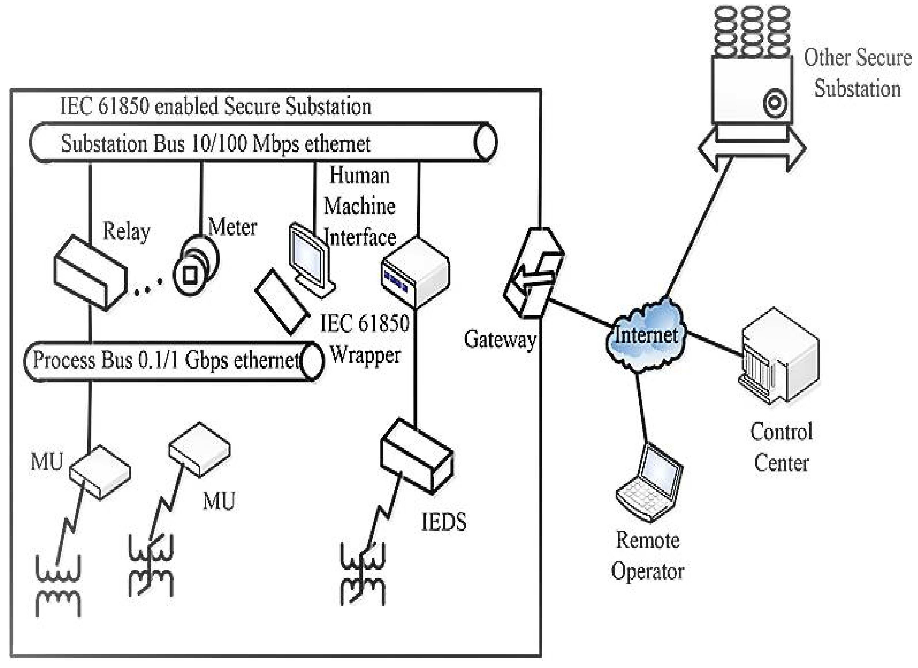
2.2. Digital Substation Communication Architecture
The architecture of the IEC 61850 standard communication model is shown in Figure 1 [26,27,28]. It is shown in the figure that it has two buses for communication:
Figure 1.
IEC-61850-based substation communication architecture.
- Station Bus: This bus is carrying all the required information of protective relays or IEDs and substation supervisory control and data acquisition (SCADA) system operation. The substation controlling and monitoring are performed through this communication bus.
- Process Bus: This bus is used to interconnect the IEDs with current transformers (CTs)/ potential transformers (PTs) or other field devices. It reduces the construction and maintenance cost by removing the data communication wires. It also houses the merging units for vertical communications with other units or substations.
The single-bay digital substation model proposed in this study has a single process bus, connecting the process level and bay level through the Ethernet network of the substation. The Process level has the omicron test tool kit acting as the field measuring device of the substation for injecting analog inputs in the model and an AMU for data conversion. The bay level has two IEDs that were tested for validation of the hardware prototype developed.
2.3. Benefits and Limitations of Implementing IEC 61850 Standards in Substations
IEC 61850 standard implementation serves the following purposes in a substation [29,30,31]:
- It improves the power quality and reduces copper wirings plugged into IEDs with a faster response to substation faults.
- Interoperability of IEDs and substation devices.
- Reduction in operation and maintenance cost of substations.
- Faster data transmission among substation devices.
- Substation operation and future expansion become easy due to the flexible functionality of IEC 61850.
Despite the above advantages, the IEC 61850 standard offers certain restrictions:
- Implementation of IEC 61850 in existing substations requires either the removal or upgrade of old substation devices and additional cost investments.
- IEC 61850 implementation requires the processing and storage of a huge amount of real-time data.
- Single vendor devices can cooperate easily in single zone protection and operation only. However, the substation level devices from different vendors need to be connected to a common network of communication. The challenge here is to build cooperation among devices. In addition, successful testing of device interoperability needs to be performed before application in a real-time operational substation.
3. System Configuration Steps and Challenges
The proposed multivendor testbed was configured with some device software platforms, which will be explained in the next section. The single-bay digital substation was integrated using IEC 61850 SCL files. Hardware integration and their operational barriers have helped here in identifying the configuration problems that could be faced with this type of model. The measures performed in the study to overcome the problems mentioned and to make the system interoperable would help engineers to understand it better and to opt for multivendor systems in substations. Here, the integration process followed, the interoperability problems faced, and their solutions are discussed.
3.1. Integration of Multivendor Digital Substation
Integration of the complete model with multivendor devices was executed by following the steps shown in Figure 2.
Figure 2.
Integration steps of the multivendor testbed.
Step 1:
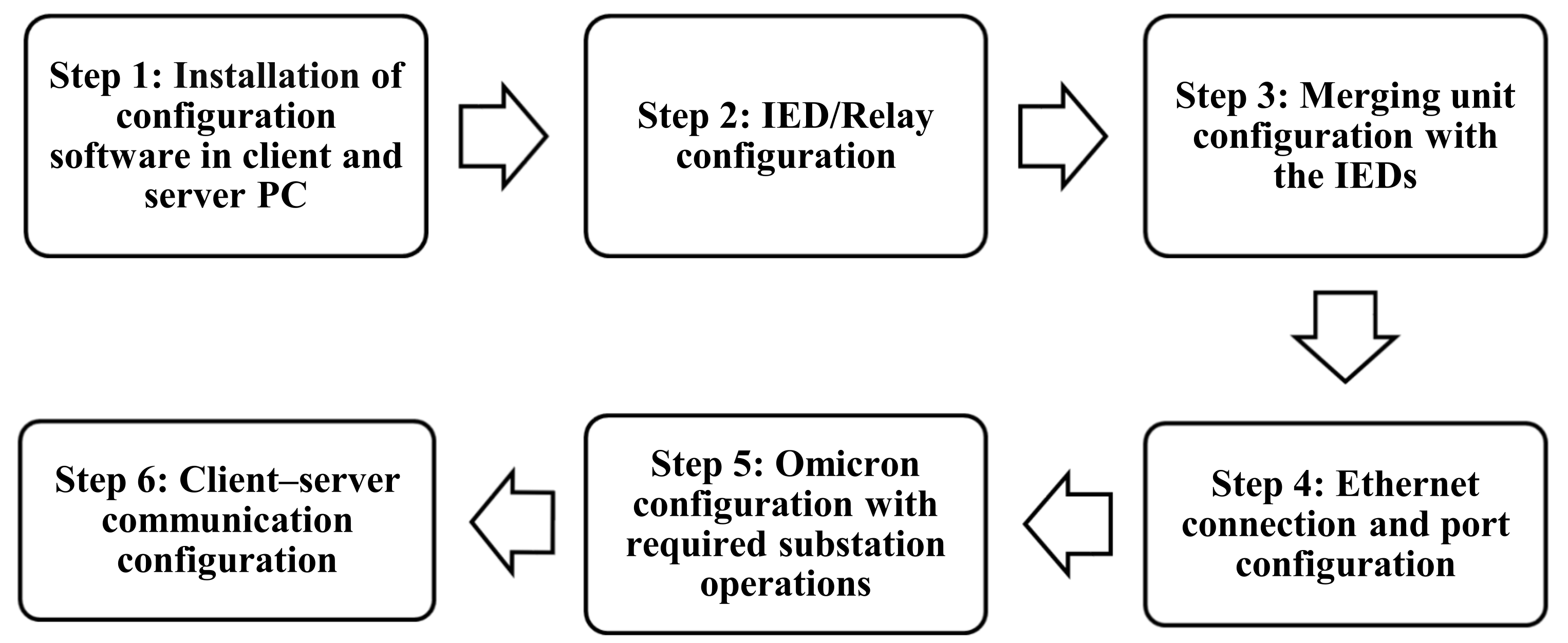
- Protection and control IED manager (PCM) 600 was installed in the client PC for the configuration of a single-bay digital substation.
- Wire shark software was installed on the client PC to monitor the travelling data packets.
- IED scout software was installed in both client and server PCs for mapping client–server communications.
Step 2:
- The substation IEDs that are needed in the testbed—that is, REL 670 and REC 670—were added to the PCM600 platform.
- A new project was built to configure the multivendor testbed in the PCM600 software.
- The IED configurations were produced in two sections:
- i.
- IED configuration and
- ii.
- Application configuration (designed all required function blocks).
- The configuration data stored in the SCL files were read and imported into PCM600 for both the IEDs.
Step 3:
- The Vizimax commissioning tool (VCT) was installed in the client PC for AMU configuration.
- Set up of the AMU attributes was performed to match the required substation operations and interoperation of IEDs.
- In PCM600, the configuration of AMU with local Ethernet port addressing was completed.
- Function blocks were designed as per the desired operations of the AMU using the PCM600 application configuration.
Step 4:
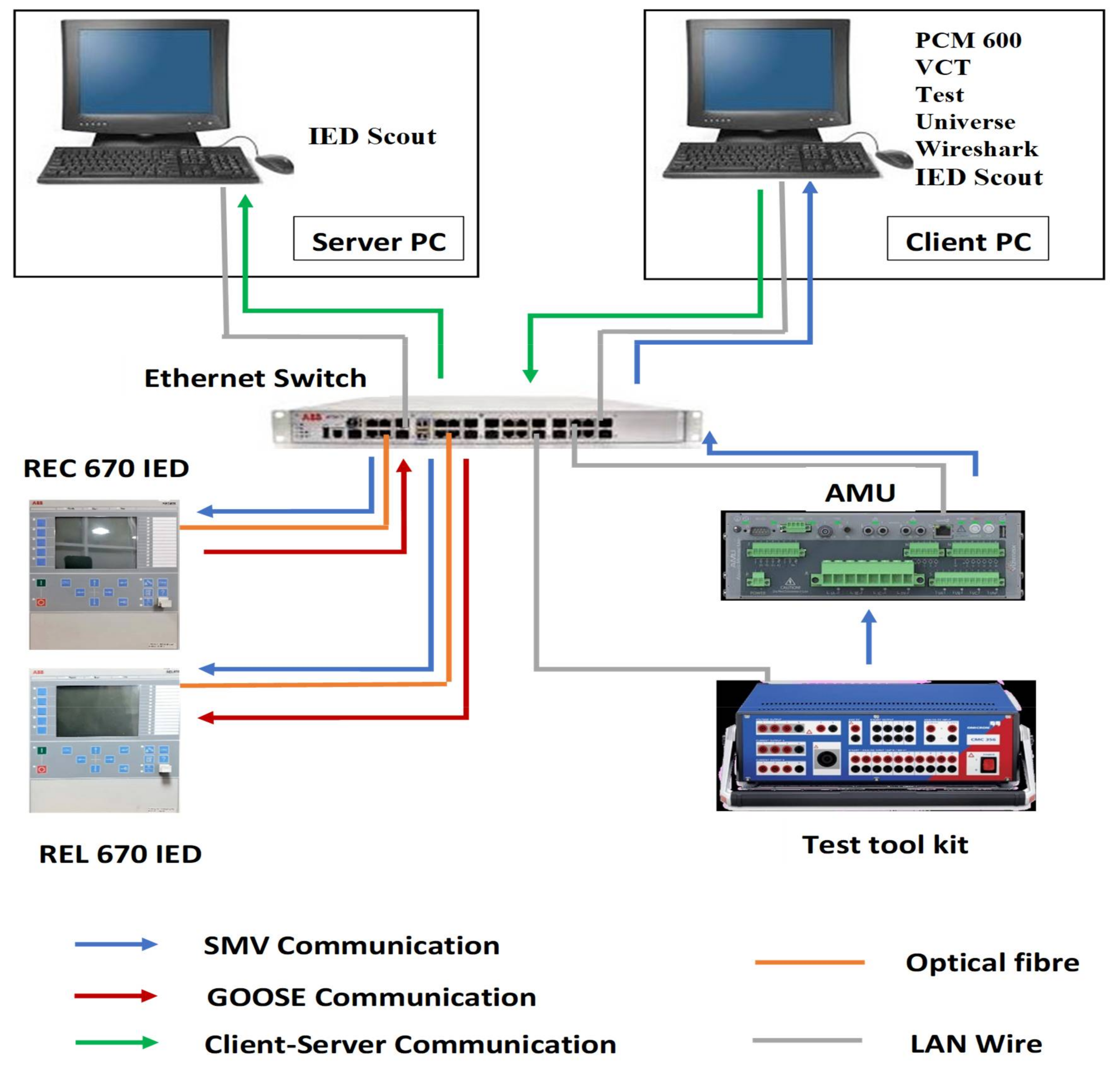
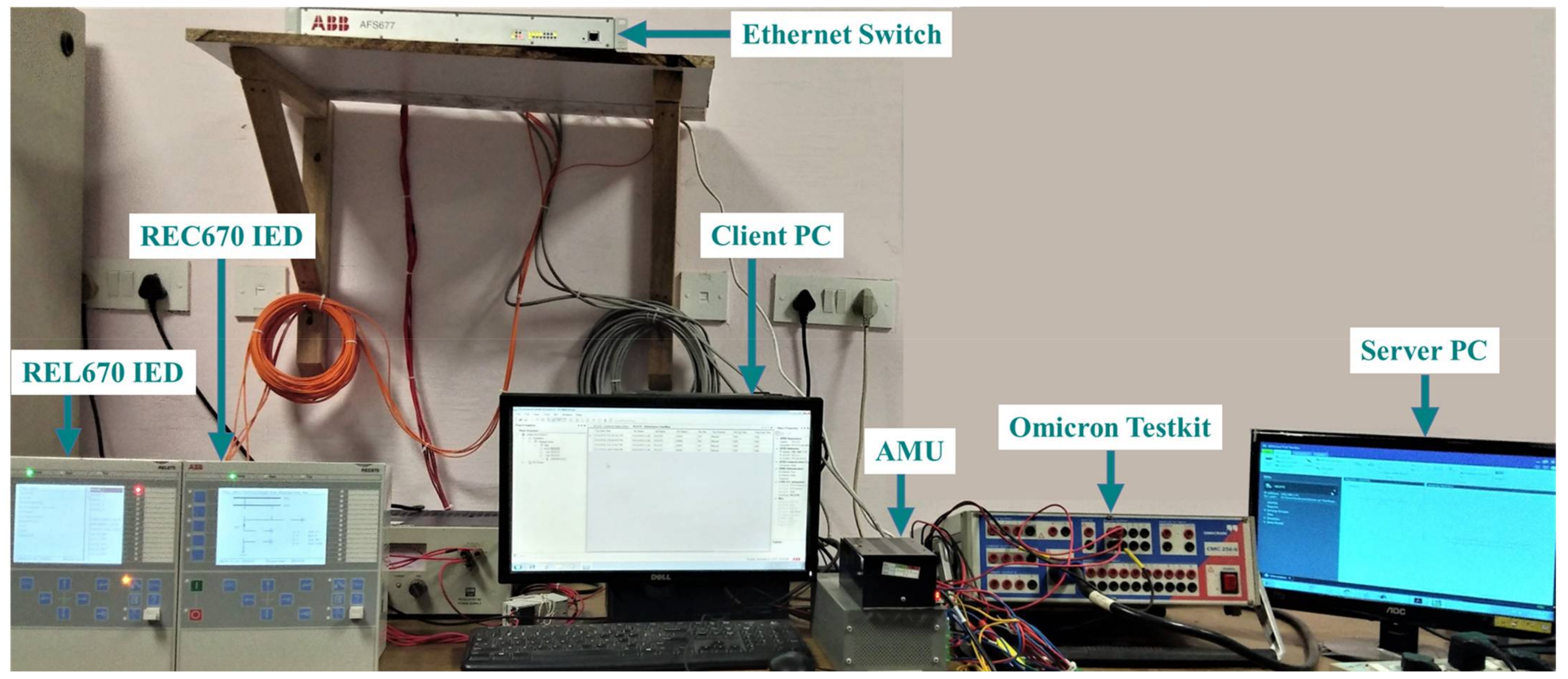
- A communication network was developed by connecting the AMU, omicron test kit, client PC, and server PC with the Ethernet switch using local area network (LAN) wires.
- Both the IEDs were connected with FO cables to the Ethernet ports.
- For transferring messages through the process bus communication network, all devices were configured to a common local IP address channel that had different verticals.
Step 5:
- Omicron test universe software was installed in the client PC to inject and monitor the substation inputs from the omicron test kit.
- The test kit configurations were completed according to the prototype test requirements.
- The input values to be injected for testing the SMV and the trip time settings for protection studies were performed.
Step 6:
- Substation configuration description (SCD) files for both IEDs were generated and imported in the IED scout software of the server PC.
- The LNs of devices were built in the software, using which we could monitor the SMV of the respective IEDs and protection operations.
- Lastly, monitoring of the GOOSE messages from the sniffer application of the IED scout software was achieved.
3.2. Demonstration of Configuration Challenges and Solutions
The prototype configuration process discussed in the previous section faced some configuration challenges as the system had multivendor devices. The ABB IEDs and Ethernet switch interoperability with Vizimax AMU were interrupted because of differences in their vendor-specific configurations and device versions, as discussed below.
3.2.1. Differences in Edition (Ed.) and ICD Files of Devices
Two editions of devices Ed.1 and Ed.2 were available for the IEDs and AMU used in the prototype. Ed.1 was taken in the IEDs, whereas Ed.2 was in the AMU because of vendor differences. The IED configuration description (ICD) files of an IED and AMU are vendor-specific, and thus they may have different editions. Therefore, interoperability testing of the devices was not possible in the testbed.
As a solution, the ICD files for Ed.1 from Vizimax were configured in the AMU and then were updated according to the system requirements by editing using the note pad/XML marker.
3.2.2. Incompatible Device Firmware
Due to the reconfiguration of AMU to Ed.1, the firmware failed to support the AMU functioning and needed to be upgraded. To solve this problem, the existing firmware version of AMU, which was 21997-1 V 1.2.0.11 was upgraded to firmware version 1.2.3. The firmware up-gradation was performed with the updated firmware file and tool suit connected at the USB port.
3.2.3. Limitations in Ethernet Switch
The multivendor testbed operating with Ed.1 device configuration also implements some limitations in its communications through the Ethernet switch. The ServerAt functionality of the Ethernet switch was not supported in Ed.1. This implies that the network configuration will be limited to only Ethernet port 1 for all types of messages travelling in a system. Therefore, in this system, the Ethernet was reconfigured again for communication of both SMV and GOOSE messages through port 1 only.
4. Development of Multivendor Digital Substation
4.1. Single-Bay Digital Substation
To obtain a better understanding and to perform interoperability testing of substation devices, a laboratory testbed was designed in this study by taking devices from different vendors as shown in Figure 3. The devices used in the laboratory setup are listed in Table 2 with their respective operational configurations.
Figure 3.
Connection diagram of the single-bay digital substation.
Table 2.
Details of devices used in the substation prototype.
The IEC 61850 standards that were configured in both the IEDs were IEC 61850-8-1 for GOOSE messaging and IEC 61850-9-2 for SMV communications. To test the process bus communications, analog input values were injected here from the omicron kit and transferred to the IEDs after being converted into digital form by the AMU that was connected at the omicron output terminals. The communication network had an Ethernet switch that was connected to both the IEDs using FO patch cables. Other prototype devices, such as AMU, omicron test kit, client PC, and server PC, were connected via LAN wires to the Ethernet ports. For time synchronization, one of the IED (REL670) time settings was taken as the standard reference, and all other devices were synchronized with the IED for the same time configuration. The hardware setup is shown in Figure 4.
Figure 4.
Single-bay substation testbed with multivendor devices.
This model can be extended in the future with more IEDs, AMUs, and different vendor-specific devices connected in a more advanced network topology. If a dedicated SCADA system can be added with some modifications of this model, it may become possible to interconnect DERs in the IEC-61850-based substation model, considering the concepts discussed in [32,33]. In addition, a DER microgrid architecture can be developed and tested with the latest IoT protocol mapping of the IEC 61850 standard, as discussed in [34]. Some of the latest reliable network topologies can be formed using concepts such as the integer linear programming (ILP) model [35].
4.2. Software Tools Used
The prototype model configuration and interoperability testing require some software tools to be installed in the system. All software tools installed in this model are given in Table 3 below.
Table 3.
Details of software tools used in the substation prototype.
The PCM600 is an IED configuration software from ABB that is compliant with IEC 61850 and was used in this prototype to simplify the IED operations. With this software, information exchange between IEDs has become possible and it can also be used to edit the topology of the existing power system network. The PCM600 provides here an easy-to-use configuration possibility that can be used for signal transfer monitoring and injected input/output monitoring. The merging unit configuration was performed in the client PC using VCT, which is a configuration software from Vizimax. The object attributes, user-defined configurations, and local IP addresses of the AMU were updated using this tool.
Test universe is a powerful tool used for settings-based testing of IEDs using an omicron kit. This software was installed on the client PC for injection of inputs from the test kit and to monitor IED operations by tracking trip timings, SMV, and IED graphical characteristics. An open-source data packet analyzer Wireshark was installed in the client PC to capture data packets travelling during GOOSE and SMV communications. IED Scout was installed in both PCs so that the server or a remote location PC could access any station events from the client PC. This software helped to establish client–server communications in the laboratory testbed.
5. Demonstration of Multivendor Digital Substation Validation
The substation model installed in Figure 4 needs to be tested to validate the successful implementation and interoperation of the IEC-61850-based multivendor digital substation. Station interoperability, process bus communications, protection functions, and client–server communications were tested with the multivendor testbed.
5.1. Case Study 1: Demonstration of Process Bus Communication Validation
5.1.1. Testing GOOSE Communication
To test IED to IED GOOSE communications, the breaker operation stages were configured in the form of gate logics in IEDs. Here, GOOSE communications were tested between the REL670 and REC670 IEDs. As GOOSE is a type of publisher–subscriber messaging, during the test, REC670 was acting as a publisher IED and REL670 as a subscriber IED. Four logic gate were configured in the REC670 relay with corresponding breaker statuses as listed in Table 4 [36].
Table 4.
Logic gates configured for GOOSE communication.
With the manual triggering of any of these gates, REC670 will publish GOOSE messages that will be transferred to the REL670 IED. Using the PCM600 WAVEWIN visualization tool, the GOOSE publisher–subscriber message transfer between IEDs can be monitored. GOOSE messages are time-critical messages; therefore, testing the ETE delay is important. The ETE delay values of GOOSE messages travelling between the two IEDs were recorded during the test in the PCM600 disturbance recorder and are summarized in Table 5.
Table 5.
GOOSE publishing and receiving details with ETE delays.
The ETE delay values between publishing and receiving GOOSE messages by the IEDs were calculated from the timestamp frames of the successive publisher and subscriber IEDs. The formula used for the ETE delay calculation is given in Equation (1) [37]:
where is the time delay, is the subscriber or receiver timestamp, and is the publisher or transmitter timestamp.
In this equation, the time delay is calculated by measuring the difference of time between the timestamps of the published GOOSE message by the publisher IED to the subscribed GOOSE message of the subscriber IED. The ETE delay of GOOSE messages in a digital substation should be less than 3 ms (<3 milliseconds), and the test results show that ETE delays of the implemented testbed lie within the standard limits.
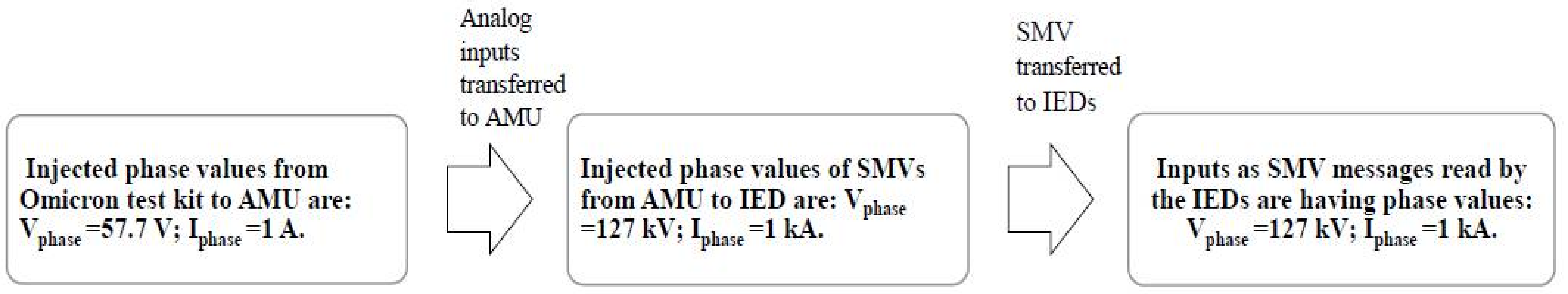
5.1.2. Testing SMV Communication
To test SMV communications, analog inputs from the field devices should travel through the process bus to the station IEDs. In this testbed, the omicron test kit is used to inject the analog inputs of the substation in the form of balanced voltage and current to the AMU.
The substation model implemented in this study had ratings of 220 kV and 1 kA. The omicron had settings of turn ratios for CT and PT inputs, which were performed using test universe software. With the turn ratio settings, the line values in the secondary of the omicron kit were and [38]. The input values that were injected from the omicron secondary to the model are voltage and current phase values that can be calculated using Equations (2) and (3) corresponding to the line values. The injected phase voltage and current values are given in Table 6 and were calculated using Equations (4) and (5).
where is the phase voltage, is the line voltage, is the phase current, and is the line current. Here Equations (2) and (3) represent the basic relation between the phase voltage and current in a power system network.
Table 6.
Input values of voltages and currents injected in the substation.
The injected inputs will travel through the turns ratio meter (TRM) of the CT/ PT ports in the AMU and then be converted into digital signals or SMV messages. The TRM settings of the AMU were configured with the following turns ratios [39]:
CT turns ratio—1000:1
PT turns ratio—1:2200
After travelling through the AMU, SMV messages will now have the considered substation input values of 220 kV and 1 kA. These SMV messages will then travel through the Ethernet network and will be transferred to the IEDs. SMV messages with voltage (refer to Equation (2)) and current (refer to Equation (3)) will be received by the REC670 IED. The IED was preconfigured to capture the SMV events and record them in a disturbance recorder file.
The process of transferring SMV messages and corresponding values of the injected inputs in each level: from the omicron test kit to the AMU and from the AMU through the Ethernet network to the IEDs are shown in Figure 5.
Figure 5.
Input injection and transfer from omicron kit to IEDs with corresponding input values at different levels.
The process bus communication test results confirm that the multivendor substation devices are interoperating with each other successfully. In addition, the data packets travelling during the communications can be visualized using Wireshark software.
5.2. Case Study 2: Demonstration of IED Protection Operations Validation
The protection operations were tested on one IED REL670 of the testbed, which was configured with the required protection functions. The tests were executed by injecting the analog current and voltage values from the omicron test kit to the AMU, and after converting them into SMV messages, they were transferred to the IED. Three types of protection operations—overcurrent, earth fault, and overvoltage protections—were studied here with IED settings for the IEC standard inverse curve. The relationships between different fault current values and their corresponding IED operating times were analyzed in this study with the formation of inverse definite minimum time (IDMT) curves.
In IED protection operations, time multiplier settings (TMS) are used to vary the operation time of IEDs proportionally. TMS values were calculated using Equation (6).
where T represents the desired operating time of IED, and Tm is the operating time corresponding to TMS 1.0. This equation is a standard equation that is used in any relay or IED for the calculation of TMS.
The equation for the trip time (t) calculation of different IEC curves is given in Equation (7). The tripping time (t) for the IEC standard inverse curve can be calculated using Equation (8).
where I is the fault current value, Is is the pickup current, and the ratio represents the plug multiplier setting (PMS). β is the relay characteristics constant, and α is the inverse time type constant of IED [40]. Equation (7) is a standard equation defined in IEC 61850 standards for the calculation of tripping time in an IED during a fault condition, and this depends on the TMS setting, PMS setting, IED constant given by the manufacturer, and the type of inverse curve need to be obtained.
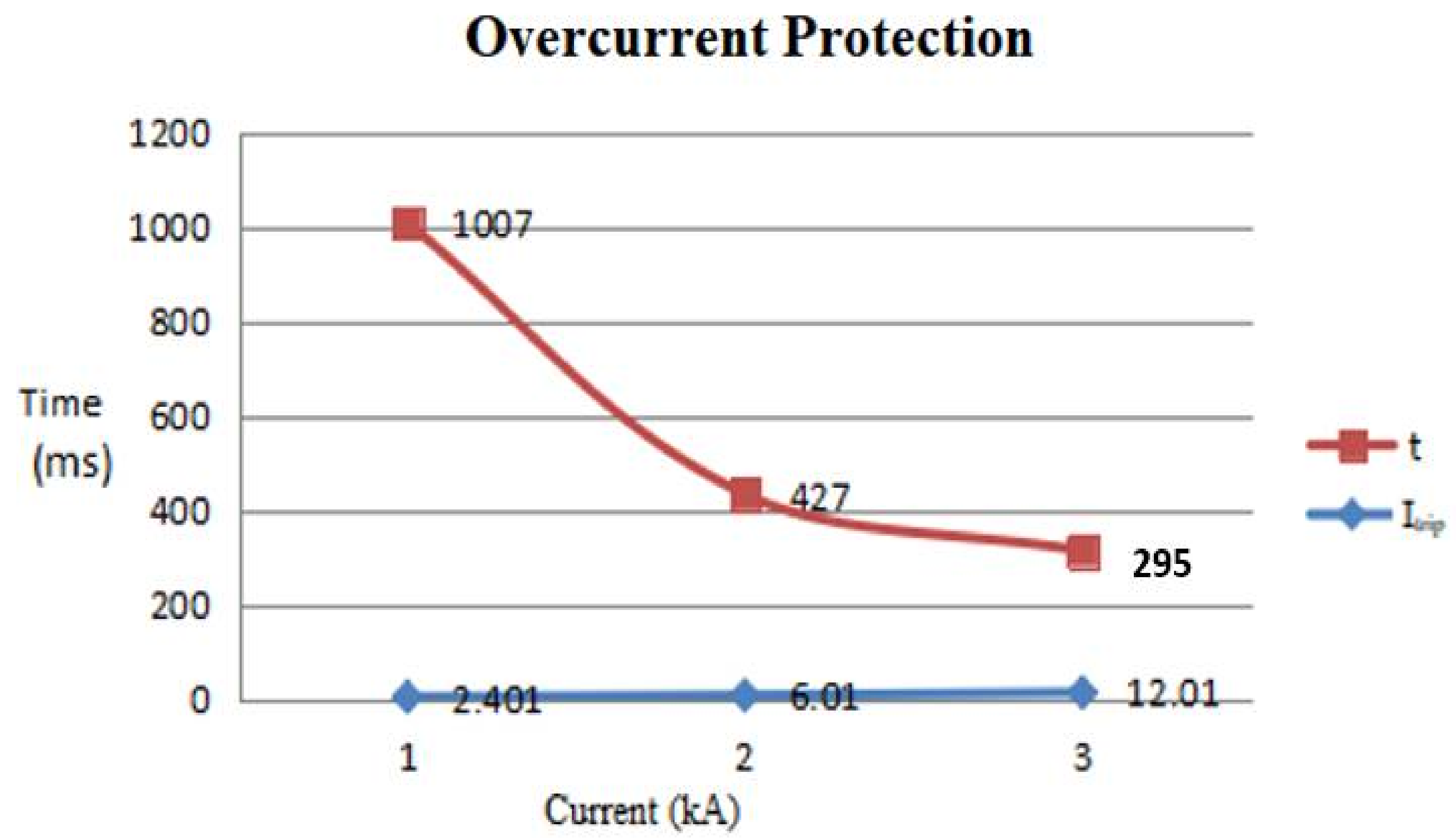
5.2.1. Testing IED Overcurrent Protection
The overcurrent protection was tested on the REL670 IED considering TMS as 0.1 for a faster response of the IED to the fault. The IDMT curve was obtained in any one phase according to the IED time of operation with injected increasing values of the fault currents while keeping the other two phase currents undisturbed. The substation rated current, trip current, and increasing values of trip currents injected from the omicron test kit are given in Equations (9)–(11).
Overcurrent IED settings:
;
Trip current in each phase (;
Trip current values injected in each phase:
In equations 9 to 11, three increasing values of trip currents were calculated to measure the corresponding IED trip timings so that the IDMT curve of the IEDs could be obtained. For all of the above trip currents, the corresponding IED trip timings were recorded and listed. The trip timings with corresponding fault current values were also calculated mathematically using Equation (8), which was for the IEC standard inverse curve. Both the trip timings as IED operated and mathematically calculated for corresponding trip currents are given in Table 7. The IDMT curve obtained from the test for any phase (R phase) is shown in Figure 6.
Table 7.
Overcurrent protection IED trip timings corresponding to the trip current values.
Figure 6.
IDMT curve obtained from the overcurrent protection test of IED.
5.2.2. Testing IED Earth Fault Protection
The earth fault protection testing of the REL670 IED was performed using TMS 0.1. It was tested by injecting increasing values of unbalanced currents in the overall IED or the total current in all three phases. The unbalanced current value and increasing values of trip currents injected from the omicron test kit are given in Equations (12)–(14).
Earth fault IED Settings:
Unbalance current: (.
Trip current values injected in the system:
In Equations (12) to (14), three increasing values of trip currents were calculated by considering the rated current value and increasing the unbalance current to measure the corresponding IED trip timings so that the IDMT curve of the IEDs can be obtained. For all the above trip currents, the corresponding trip timings are recorded and listed. The trip timings were also calculated mathematically with their respective operating current values using Equation (8). Both the trip timings as IED operated and mathematically calculated for corresponding trip currents are given in Table 8. The IDMT curve of the IED obtained for earth fault protection is shown in Figure 7.
Table 8.
Earth fault protection IED trip timings corresponding to the trip current values.
Figure 7.
IDMT curve obtained from the earth fault protection test of IED.
5.2.3. Testing IED Overvoltage Protection
The overvoltage protection was tested on the REL670 IED, by taking the TMS value of 0.5. In overvoltage protection, the IED follows a normal definite time curve, as, in this protection, the IED needs to be tripped exactly at the predefined setpoint of time corresponding to the fault voltage given in Equation (15).
Overvoltage IED Settings:
; input rated voltage: .
Fault voltage in any phase:
The setting of time for IED tripping . The trip time taken by the IED to operate during the test for an overvoltage value of 120% is given in Table 9.
Table 9.
Overvoltage protection IED trip time corresponding to the fault voltage value.
5.3. Testing Client-Server Communication
The GOOSE and SMV messages of publisher–subscriber IEDs with time stamps can be monitored using IED scout visualization software from a server PC connected to the same Ethernet network. The required SCD files of the substation model must be uploaded to the server PC. Then, the IED that needs to be monitored will be selected. The process bus communications were monitored here using a sniffer application and GGIO LN for GOOSE and CMMXU/VMMXU LN applications (CMMXU for current and VMMXU for voltage) for SMV.
6. Conclusions
This study investigated a testbed model of an IEC-61850-based digital substation that was developed by taking substation devices from different vendors. The substation device interoperability, process bus communications, protection operations, and data monitoring were studied using the testbed. We presented a discussion regarding the basics of IEC 61850 standards and digital substations. The system configuration with a multivendor approach and real-time configuration challenges are highlighted in this study.
The configuration challenges were faced due to the differences in device edition, their firmware, and Ethernet communication ports. The solutions to overcome all the above challenges were discussed in detail. The development of a single-bay digital substation model was discussed with all the devices and software used in it. The interoperability of devices with GOOSE and SMV message transfer between the IEDs and other substation devices was tested successfully with the development of visualization platforms for monitoring data packets.
The GOOSE messages ETE delay was 2 ms, which is within the standard limits, and in SMV, the IEDs were reading the exact injected input values. Three types of IED protection operations were tested for recording IED response timings corresponding to the fault current/voltage ratings. In addition, the results were verified mathematically and graphically. The client–server communication feature in an IEC-61850-based substation was tested by monitoring substation events from a remote server.
Substation devices from the same manufacturer may not be available during the replacement of existing substation devices when they are damaged. In this scenario, the interoperability of IEDs and AMUs from multiple vendors will be needed, which can also reduce the cost and time of reinstallation. Thus, the motive of this study was to understand IEC-61850-based multivendor digital substations and to highlight some of the issues that can be faced by substation engineers using multivendor installations with possible solutions.
Substation prototype testing is important before implementing any multivendor system in a real substation. In this case, the test results studied here with the multivendor testbed will support substation engineers in installing a multivendor substation. The problems faced in the system configuration also depict the need for standardization in IEC-61850-based systems. However, this system has only single-bay operations with a limited number of substation devices and no SCADA-controlled operations.
Thus, studies of systems with more complex architectures, more multivendor devices, and reliable network topology should be performed to ensure the interoperability of devices in a real-time substation operation. This testbed will be upgraded in the future with the installation of more IEDs from different vendors and with multiple bay operations to obtain a more reliable model with multivendor solutions. A dedicated SCADA system will be installed in the extended future model to enable substation controlling operations from a remote server and for integration of DER systems into the model.
Author Contributions
Conceptualization, T.B., M.J., H.M. and M.A.A.; methodology, T.B., M.J., H.M. and M.A.A.; software, T.B., M.J., H.M., M.E.N. and M.A.A.; validation, T.B., M.J., H.M., M.E.N. and M.A.A.; formal analysis, T.B., M.J., H.M. and M.A.A.; investigation, T.B., M.J., H.M. and M.A.A.; resources, Not applicable T.B., M.J., H.M., M.E.N. and M.A.A.; data curation, T.B., M.J., H.M., M.E.N. and M.A.A.; writing—original draft preparation, T.B., M.J., H.M. and M.A.A.; writing—review and editing, T.B., M.J., H.M., M.E.N. and M.A.A.; visualization, T.B., M.J., H.M., M.E.N. and M.A.A.; supervision, M.J. and M.E.N.; project administration, H.M. and M.A.A.; funding acquisition, H.M. and M.A.A. All authors have read and agreed to the published version of the manuscript.
Funding
The authors extend their appreciation to the Researchers Supporting Project at King Saud University, Riyadh, Saudi Arabia, for funding this research work through the project number RSP-2021/278.
Institutional Review Board Statement
Not applicable.
Informed Consent Statement
Not applicable.
Data Availability Statement
Not applicable.
Acknowledgments
The authors would like to acknowledge the support from Intelligent Prognostic Private Limited Delhi, India Researcher’s Supporting Project (XX-01/2022), Intelligent Prognostic Private Limited Delhi, India. The authors would like to acknowledge the support from King Saud University, Saudi Arabia, and the University of Waterloo, Canada.
Conflicts of Interest
The authors declare no conflict of interest.
Nomenclature
| Acronyms | |
| AMU | analog merging unit |
| CT | current transformer |
| DER | distributed energy resource |
| Ed | edition |
| ETE | end-to-end |
| FO | fiber optic |
| LD | logical device |
| LN | logical node |
| OPNET | optimized network engineering tool |
| PMS | plug multiplier setting |
| PT | potential transformer |
| PCM | protection and control IED manager |
| SMV | sampled measured value |
| SAS | substation automation system |
| GOOSE | generic object-oriented substation event |
| ICD | IED configuration description |
| ILP | integer linear programming |
| IED | intelligent electronic device |
| IEC | international electrotechnical commission |
| IDMT | inverse definite minimum time |
| LAN | local area network |
| SCN | substation communication network |
| SCD | substation configuration description |
| SCL | substation configuration language |
| SCADA | supervisory control and data acquisition |
| TMS | time multiplier setting |
| TRM | turns ratio meter |
| VUZS | Victoria university zone substation |
| VCT | Vizimax commissioning tool |
| Notations | |
| α | inverse time type constant of IED [-] |
| β | relay characteristics constant [-] |
| I | fault current value [A] |
| Is | pickup current [A] |
| rated current [A] | |
| phase current [A] | |
| line current [A] | |
| trip current [A] | |
| unbalance current [A] | |
| t | trip time [s] |
| setting of time for IED tripping [s] | |
| T | desired operating time of IED [s] |
| Tm | operating time corresponding to TMS 1.0 [s] |
| subscriber or receiver timestamp [s] | |
| time delay [s] | |
| publisher or transmitter timestamp [s] | |
| line voltage [V] | |
| phase voltage [V] | |
| rated voltage [V] | |
| fault voltage [V] | |
| voltage setting [V] |
References
- Janssen, M.C.; Koreman, C.G.A. Substation Components Plug and Play Instead of Plug and Pray: The Impact of IEC 61850; Kema T&D Power: Amsterdam, The Netherlands, 2013; Available online: http://www.Nettedautomation.com/standardization/IEC_TC57/WG10_12/index (accessed on 7 June 2021).
- Zhu, L.; Shi, D.; Wang, P. IEC 61850-based information model and configuration description of communication network in substation automation. IEEE Trans. Power Del. 2013, 29, 97–107. [Google Scholar] [CrossRef]
- Järventausta, P.; Repo, S.; Rautiainen, A.; Partanen, J. Smart grid power system control in distributed generation environment. Annu. Rev. Control. 2010, 34, 277–286. [Google Scholar] [CrossRef]
- Talaat, M.; Alsayyari, A.S.; Alblawi, A.; Hatata, A.Y. Hybrid-cloud-based data processing for power system monitoring in smart grids. Sustain. Cities Soc. 2020, 55, 102049. [Google Scholar] [CrossRef]
- International Electrotechnical Commission. Communication Networks and Systems for Power Utility Automation—Part 8-1: Specific Communication Service Mapping (SCSM)–Mappings to MMS (ISO 9506-1 and ISO 9506-2) and to ISO/IEC 8802-3, 2nd ed.; IEC: Geneva, Switzerland, 2011; pp. 1–386. [Google Scholar]
- International Electrotechnical Commission. Communication Networks and Systems for Power Utility Automation–Part 9-2: Specific Communication Service Mapping (SCSM)–Sampled Values Over ISO/IEC 8802-3, 2nd ed.; IEC: Geneva, Switzerland, 2011; pp. 1–55. [Google Scholar]
- UCA International Users Group. IEC 61850 9-2 Light Edition. Implementation Guideline for Digital Interface to Instrument Transformers Using IEC 61850-9-2 R2-1; UCA International Users Group: Raleigh, NC, USA, 2004; Available online: http://iec61850.ucaiug.org/Implementation%20Guidelines/DigIF_spec_9-2LE_R2-1_040707-CB.pdf (accessed on 25 June 2021).
- Dawidczak, H.; Englert, H. IEC 61850 Interoperability and Use of Flexible Object Modelling and Naming; Siemens AG, Energy Automation: Nuremberg, Germany, 11 July 2012; Available online: http://romvchvlcomm.pbworks.com/f/Paper+Dawidczak_Englert_RZA2010.pdf (accessed on 1 July 2021).
- Tan, J.C.; Zhang, C.; Bo, Z.Q. The Importance of IEC 61850 Interoperability Testing; UPEC, IEEE: Padua, Italy, 2008; pp. 1–5. [Google Scholar]
- Zheng, Y.; Wu, M.; Peng, Z. A close-loop conformance testing system of IEC 61850. J. Commun. 2016, 11, 779–784. [Google Scholar] [CrossRef]
- Xu, L.; Li, H.; Chen, L.; Patterson, C.; Mohapatra, P. Assessment and analysis of different process bus redundancy networks performance for IEC61850-based digital substation. J. Engg. 2018, 15, 856–860. [Google Scholar] [CrossRef]
- Claveria, J.; Kalam, A. The influence of IEC 61850 standard: Implementation and development of a functional substation automation simulator. Aust. J. Electri. Electro. Engg. 2020, 17, 28–35. [Google Scholar] [CrossRef]
- Tebekaemi, E.; Wijesekera, D. Designing an IEC 61850 based power distribution substation simulation/emulation testbed for cyber-physical security studies. In Proceedings of the CYBER 2016: The First International Conference on Cyber-Technologies and Cyber-Systems, Venice, Italy, 9–13 October 2016; pp. 41–49. [Google Scholar]
- Delavari, A.; Brunelle, P.; Mugombozi, C.F. Real-time modeling and testing of distance protection relay based on IEC 61850 protocol. Can. J. Electri. Comp. Engg. 2020, 43, 157–162. [Google Scholar] [CrossRef]
- Zadeh, M.R.; Sidhu, T.S.; Klimek, A. Implementation and testing of directional comparison bus protection based on IEC61850 process bus. IEEE Trans. Power Del. 2011, 26, 1530–1537. [Google Scholar] [CrossRef]
- Elbez, G.; Keller, H.B.; Hagenmeyer, V. A cost-efficient software testbed for cyber-physical security in IEC 61850-based substations. In Proceedings of the 2018 IEEE International Conference on Communications, Control, and Computing Technologies for Smart Grids (SmartGridComm), Aalborg, Denmark, 29–31 October 2018; pp. 1–6. [Google Scholar]
- Wannous, K.; Toman, P.; Jurák, V.; Wasserbauer, V. Analysis of IEC 61850-9-2LE measured values using a neural network. Energies 2019, 12, 1618. [Google Scholar] [CrossRef] [Green Version]
- Ustun, T.S.; Aftab, M.A.; Ali, I.; Hussain, S.S. A Novel Scheme for Performance Evaluation of an IEC 61850-Based Active Distribution System Substation. IEEE Access 2019, 7, 123893–123902. [Google Scholar] [CrossRef]
- Jurišić, G.; Havelka, J.; Capuder, T.; Sučić, S. Laboratory Test Bed for Analyzing Fault-Detection Reaction Times of Protection Relays in Different Substation Topologies. Energies 2018, 11, 2482. [Google Scholar] [CrossRef] [Green Version]
- Ingram, D.M.E.; Schaub, P.; Taylor, R.R.; Campbell, D.A. System-Level Tests of Transformer Differential Protection Using an IEC 61850 Process Bus. IEEE Trans. Power Del. 2013, 29, 1382–1389. [Google Scholar] [CrossRef] [Green Version]
- Yang, L.; Crossley, P.A.; Zhao, J.; Li, H.; Wen, A. Impact evaluation of IEC 61850 process bus architecture on numerical protection systems. In Proceedings of the 2009 International Conference on Sustainable Power Generation and Supply, Nanjing, China, 6–7 April 2009; pp. 1–6. [Google Scholar]
- Yang, L.; Crossley, P.A.; Wen, A.; Chatfield, R.; Wright, J. Performance assessment of a IEC 61850-9-2 based protection scheme for a transmission substation. In Proceedings of the 2011 2nd IEEE PES International Conference and Exhibition on Innovative Smart Grid Technologies, Manchester, UK, 5–7 December 2011; pp. 1–5. [Google Scholar]
- Sun, X.; Redfern, M.; Crossley, P.; Yang, L.; Li, H.; Anombem, U.B.; Wen, A.; Chatfield, R. IEC 61850:9-2 process bus architecture for substation protection schemes. In Proceedings of the 2011 International Conference on Advanced Power System Automation and Protection, Beijing, China, 16–20 October 2011; Volume 2, pp. 1373–1378. [Google Scholar]
- Honeth, N.; Khurram, Z.A.; Zhao, P.; Nordstrom, L. Development of the IEC 61850–9–2 software merging unit IED test and training platform. In Proceedings of the IEEE Grenoble Conference, Grenoble, France, 16–20 June 2013; pp. 1–6. [Google Scholar]
- Sucic, S.; Havelka, J.G.; Dragicevic, T. A device-level service-oriented middleware platform for self-manageable DC microgrid applications utilizing semantic-enabled distributed energy resources. Int. J. Electr. Power Energy Syst. 2014, 54, 576–588. [Google Scholar] [CrossRef]
- Montez, L.H.C.; Stemmer, M.; Vasques, F. Simulation models for IEC 61850 communication in electrical substations using GOOSE and SMV time-critical messages. In Proceedings of the 2016 IEEE World Conference on Factory Communication Systems (WFCS), Aveiro, Portugal, 3–6 May 2016; pp. 1–8. [Google Scholar]
- Azeem, A.; Jamil, M.; Qamar, S.; Malik, H.; Thokar, R.A. Design of Hardware Setup Based on IEC 61850 Communication Protocol for Detection & Blocking of Harmonics in Power Transformer. Energies 2021, 14, 8284. [Google Scholar] [CrossRef]
- Malik, H.; Alotaibi, M.A.; Almutairi, A. Cyberattacks identification in IEC 61850 based substation using proximal support vector machine. J. Intell. Fuzzy Syst. 2022, 42, 1213–1222. [Google Scholar] [CrossRef]
- O’Reilly, R.; Solutions, E.A.; Beng, T.C.; Dogger, G. Hidden Challenges in the Implementation of 61850 in Larger Substation Automation Projects; Cooper Industries: Houston, TX, USA, 2016. [Google Scholar]
- Azeem, A.; Malik, H.; Jamil, M. Real-time harmonics analysis of digital substation equipment based on IEC-61850 using hybrid intelligent approach. J. Intell. Fuzzy Syst. 2022, 42, 741–754. [Google Scholar] [CrossRef]
- Malik, H.; Chaudhary, G.; Srivastava, S. Digital transformation through advances in artificial intelligence and machine learning. J. Intell. Fuzzy Syst. 2022, 42, 615–622. [Google Scholar] [CrossRef]
- Yadav, D. Application of IEC 61850 standard to the integration of DER with the electricity network. CIRED-Open Access Proc. J. 2021, 2020, 696–698. [Google Scholar]
- Hussain, S.M.; Aftab, M.A.; Ustun, T.S. Performance analysis of IEC 61850 messages in LTE communication for reactive power management in microgrids. Energies 2021, 13, 6011. [Google Scholar] [CrossRef]
- Jun, H.J.; Yang, H.S. Performance of the XMPP and the MQTT protocols on IEC 61850-based micro grid communication architecture. Energies 2021, 14, 5024. [Google Scholar] [CrossRef]
- Leal, A.; Botero, J.F. Defining a reliable network topology in software-defined power substations. IEEE Access 2019, 7, 4323–14339. [Google Scholar] [CrossRef]
- Bhattacharjee, T.; Jamil, M. GOOSE Publishing and Receiving Operations of IEC 61850 Enabled IEDs. In Proceedings of the 2019 IEEE 1st International Conference on Energy, Systems and Information Processing (ICESIP), Chennai, India, 4–6 July 2019; pp. 1–6. [Google Scholar] [CrossRef]
- Altaher, A.; Mocanu, S.; Thiriet, J.M. Evaluation of Time-Critical Communications for IEC 61850-Substation Network Architecture. In Proceedings of the International Conference Surveillance 8, Roanne, France, 22 December 2015. [Google Scholar]
- Jamil, M.; Rizwan, M.; Bhattacharjee, T.; Azeem, A. Digital Substations with the IEC 61850 Standard; AIP Publishing: New York, NY, USA, 2021; pp. 1–24. [Google Scholar] [CrossRef]
- Bhattacharjee, T.; Jamil, M. Real Time Operation of IEC 61850 based Digital Substation. Int. J. Eng. Adv. Technol. 2019, 9, 9119. [Google Scholar] [CrossRef]
- Soman, S.A. Power System Protection (Web) Webcoursenptel; IIT Bombay: Mumbai, India, 2009. [Google Scholar]
Publisher’s Note: MDPI stays neutral with regard to jurisdictional claims in published maps and institutional affiliations. |
© 2022 by the authors. Licensee MDPI, Basel, Switzerland. This article is an open access article distributed under the terms and conditions of the Creative Commons Attribution (CC BY) license (https://creativecommons.org/licenses/by/4.0/).