Article

Damping of Subsynchronous Resonance in Utility DFIG-Based Wind Farms Using Wide-Area Fuzzy Control Approach

by
Yaser Bostani
1,2,
Saeid Jalilzadeh
1,*,
Saleh Mobayen
1,3,*,
Thaned Rojsiraphisal
4,5,* and
Andrzej Bartoszewicz
6
1
Department of Electrical Engineering, University of Zanjan, Zanjan 45371-38791, Iran
2
Design and Development Part, Guilan Regional Electric Company, Rasht 41377-18775, Iran
3
Future Technology Research Center, National Yunlin University of Science and Technology, Douliou 64002, Taiwan
4
Advanced Research Center for Computational Simulation, Department of Mathematics, Faculty of Science, Chiang Mai University, Chiang Mai 50200, Thailand
5
Data Science Research Center, Department of Mathematics, Faculty of Science, Chiang Mai University, Chiang Mai 50200, Thailand
6
Institute of Automatic Control, Lodz University of Technology, 18 Stefanowskiego St., 90-537 Lodz, Poland
*
Authors to whom correspondence should be addressed.
Energies 2022, 15(5), 1787; https://doi.org/10.3390/en15051787
Submission received: 15 January 2022 / Revised: 17 February 2022 / Accepted: 21 February 2022 / Published: 28 February 2022

Abstract

:
This paper presents a novel fuzzy control scheme for damping the subsynchronous resonance (SSR) according to the wide-area measurement system (WAMS) in power systems including doubly fed induction generator (DFIG)-based wind farms connected to series capacitive compensated transmission networks. The SSR damping is attained by adding the fuzzy controller as a supplementary signal at the stator voltage loop of the grid-side converter (GSC) of DFIG wind farms. Additionally, time delays due to communication signals are important when using WAMSs. If the time delays are ignored, it causes system instability. In this paper, the time delays are modeled with a separate fuzzy input to the controller. The new fuzzy control approach is executed by using the angular velocity of synchronous generators (w) and its variation in the angular velocity (dw/dt). The effectiveness and success of the WAMS-based fuzzy controller is demonstrated by comparison with the particle swarm optimization (PSO) and imperialist competitive algorithm (ICA) optimization methods. The efficacy and validity of the planned auxiliary damping control are verified on a modified version of the IEEE second benchmark model including DFIG-based wind farms via time simulations using the MATLAB/Simulink toolbox.

1. Introduction

Due to the restructuring of power systems, system features have changed somewhat, including the transmission system, and have exceeded their stable ranges [1]. The problems experienced in the construction of power transmission lines have forced the generating institutions to obtain maximum efficiency from energy transmission lines by methods such as compensation [2]. Most of the strategies for growing the transmission energy of the strains are low cost, using capacitive series repayment [3]. The application of series capacitors causes an increase in power transmission capacity of the lines and an improvement in system stability. Despite all its advantages, series capacitors cause fluctuations with frequencies less than the network’s nominal frequency, stated as SSR [4]. On the other hand, with the increase in wind turbine production capacity and the application of the new generation of these turbines, the production capacity of wind farms has significantly increased [5]. Usually, wind farms are installed offshore; therefore, long transmission lines are needed to transfer the power of the wind farm to the power systems. As the length of transmission lines increases, the capacity of the transmission lines decreases, and limited energy can be transmitted from this line. The capacity of the lines is usually increased through series capacitors and reducing the electrical length of the line, which leads to SSR fluctuations [6]. So far, many studies have been conducted on damping the SSR. There are two main methods for mitigation of SSR: One method is auxiliary damping hardware. Flexible alternating current transmission system (FACTS) devices, such as gated-controlled series capacitors (GCSC), thyristor-controlled series capacitors (TCSC), and static var compensators (SVC), can be used to mitigate SSR [7,8]. The second method is the damping control approach. Subsynchronous resonance damping control is implemented in grid-side converters (GSCs) [9], and the control performance of various signals, such as capacitor voltage, current magnitude, and rotor speed, is analyzed.
In previous studies, power systems including the first and second IEEE benchmarks were considered, and SSR studies have been performed on them. In this study, we used a power system including DFIG-based wind farms, which have rarely been considered in previous studies. In addition, WAMS technology was used in the design of the fuzzy controller. Today, WAMS is widely used in power systems [10]. For instance, in [11], the use of WAMS was an indispensable practical subject in monitoring and controlling large-scale power systems. The roles of PDC and PMU in WAMS have been summarized. A WADC-PSS was suggested according to modal analysis using PSO methodology. The WADC-PSS input signals are the non-local machine speed measurements from the WAMS. Additionally, reference [12] discusses how methods from reinforcement learning can be exploited to the transition to a model-free and scalable wide-area oscillation damping control of power grids. In addition, the control constructions with distinct features have been presented.
Because DFIG-based wind farms are offshore and usually far from the compensated power system and transmission line, using WAMS is justified [13]. This is significant because the auxiliary control scheme is used for SSR oscillation in DFIG control, and because we employed the angular velocity and its variations in synchronous generators for auxiliary control signals. The input quantities in a WAMS is measured via phasor measurements unit (PMU), which is one of the chief parts of a WAMS. The important aspect is that the time delays measured by the PMU should be taken into account in the design of the controller. If this latency is ignored, the controller may even cause instability [14].
This paper offers a new method for decreasing subsynchronous resonance in utility DFIG-based wind farms considering time delays by the PMU measurement in communication networks.
The main novelties of the current article are presented as follows:
  • Design of a WAMS-based fuzzy control scheme that considers the communication time latencies originating from PMU measurements.
  • Decrease in the subsynchronous resonance for utility DFIG wind farms.
  • The proposed control scheme does not require adjusting the parameters of the controller.
The fuzzy controller was designed based on the Mamdani inference structures [15]. The inputs of the fuzzy controller are angular velocity and its variations, and the output is at the stator voltage loop of the GSC. The remainder of this paper is structured as follows. Section 2 describes the modeling of the IEEE benchmark, including DFIG-based wind farms. Section 3 offers the background for the SSR phenomenon in the series capacitive compensation of transmission lines. Section 4 describes the design of a wide-area fuzzy logic controller based on the Mamdani inference system. Section 5 discusses the time-domain simulation end result, and Section 6 concludes the paper.

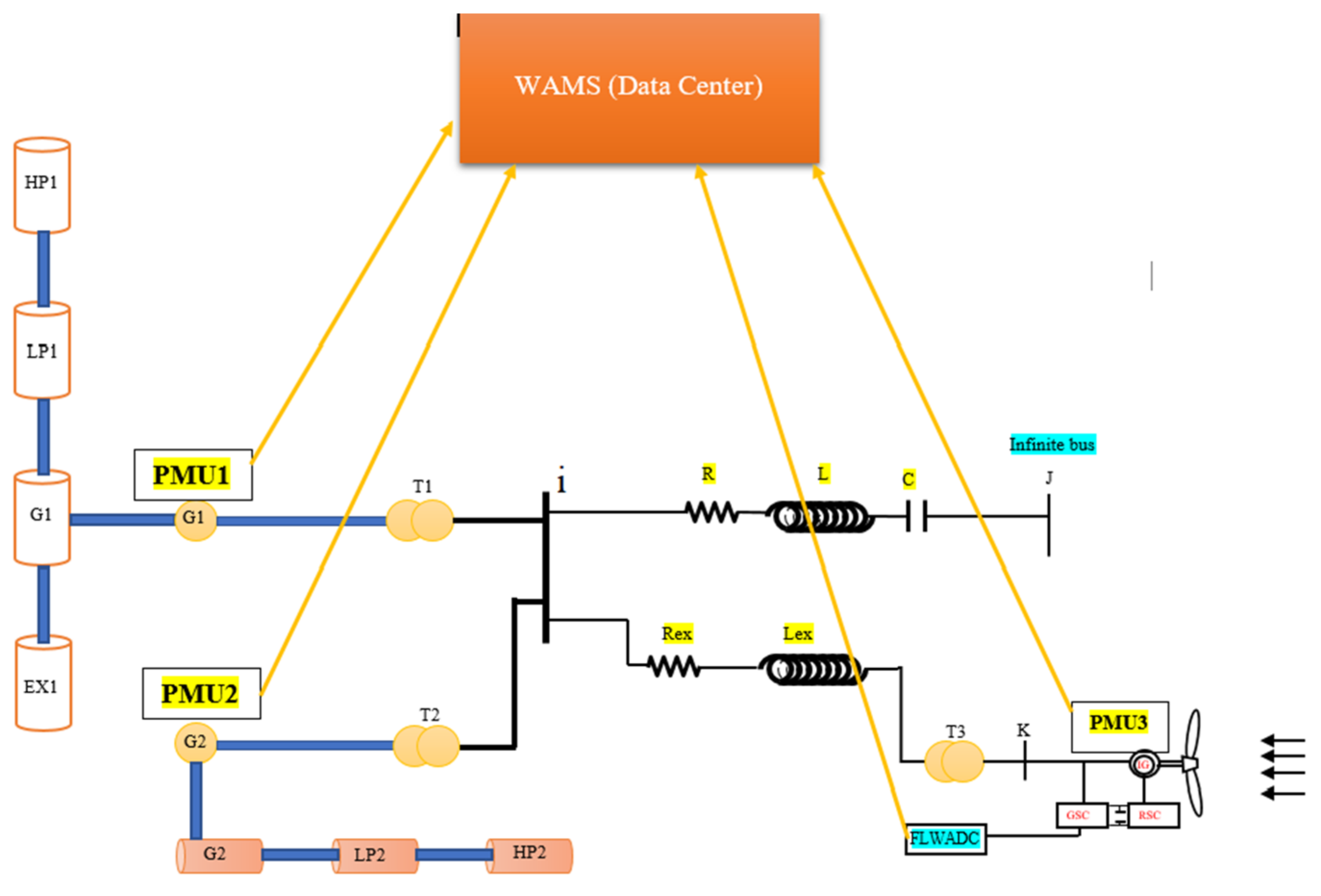
2. Modeling of the IEEE Second Benchmark including DFIG Wind Farms

In order to evaluate the efficiency of the new method in auxiliary wide-area fuzzy logic control input, the IEEE second benchmark model, improved by the inclusion of DFIG wind farms, was employed (Figure 1).
As demonstrated in Figure 1, the system has two steam generators with different turbine masses, which are connected to the infinite bus by a transmission line and DFIG-based wind farms, which are usually offshore. The dynamic model of each component represented in the above single-line diagram, which has been defined in detail in previous research, is briefly described below [16,17,18].

2.1. IEEE Second Benchmark

The standard IEEE second benchmark system has two steam-turbine-type generators, each of which has different masses, as shown in Figure 1. The first generator has four masses, HP1, LP1, G1, and EX1, so it has 3 torsion modes, HP1-LP1, LP1-G1, and G1-EX1. The second generator has 3 masses, HP1, LP1, and G1, which therefore has 2 torsional modes, HP1-LP1 and LP1-G1 [19]. In addition, the data of this system are given in Table A1.

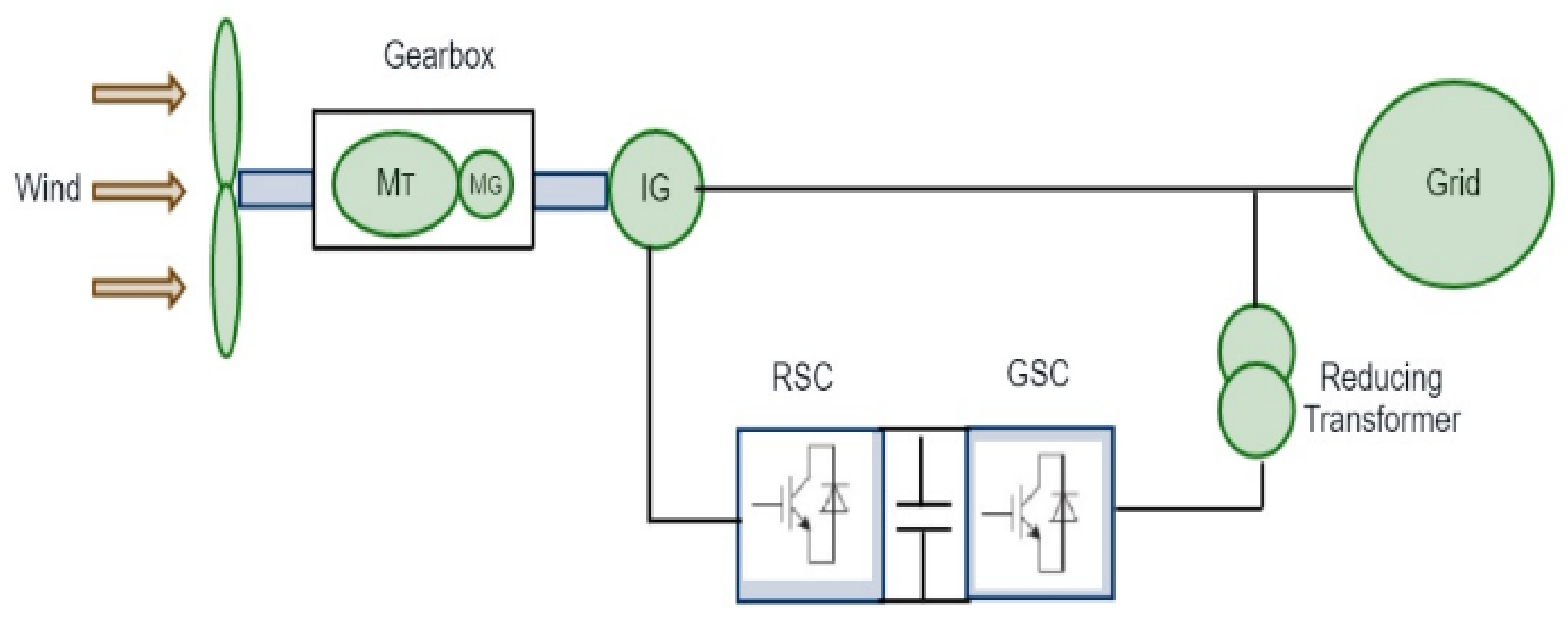
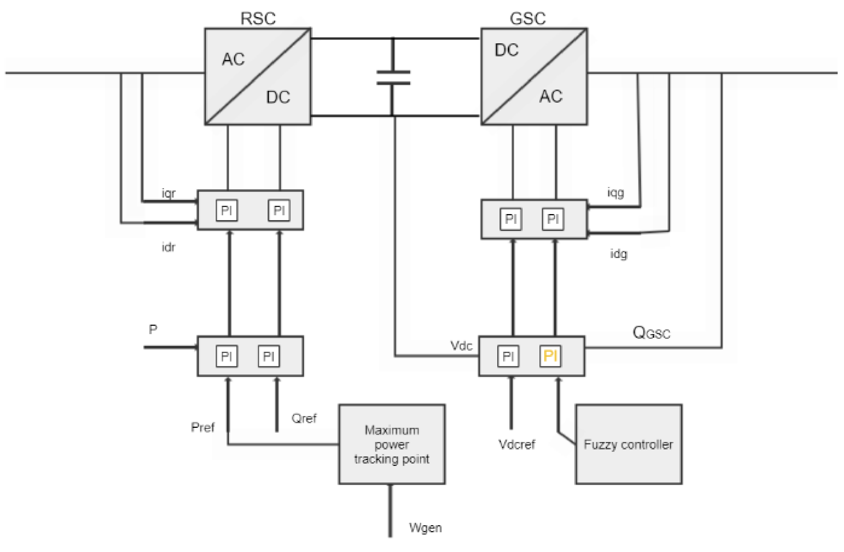
2.2. Model of DFIG-Based Wind Farm

A schematic of the DFIG- based wind farms is shown in Figure 2. The DFIG has two controllers: a rotor-side converter (RSC) and a grid-side convertor (GSC). In addition, a two-mass model was applied for the generator turbine shaft system, MT mass for low turbine speed and MG mass for high generator speed, as shown in Figure 2. In addition, the data of this system are given in Table A2.
In addition, Figure 3 shows the structure of the RSC and GSC controllers. According to Figure 3, the RSC controller is employed to control the active/reactive power of the converter, and the GSC controller is applied to control the reactive power and DC link voltage between the two converters [20].
According to references [21,22,23,24,25], a wind farm can be modeled as an equivalent wind farm because all the parameters of a wind farm are similar to an equivalent wind farm. The total power is equal to the total installed capacity of the wind turbines. For example, a wind farm with fifty 2 MW generators is modeled as one 100 MW generator [26]. The data attachments of these systems are given in the appendices.

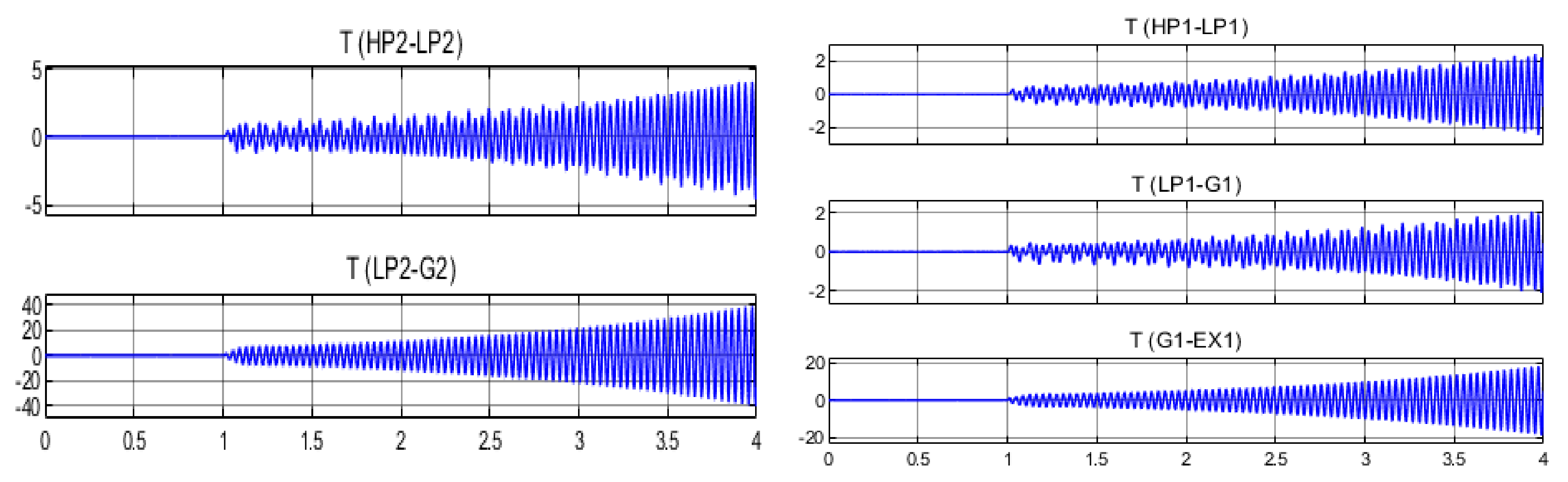
3. Definition of SSR

In this part of the paper, the concept of SSR is examined. According to the IEEE definition, SSR is a condition in the power system that is associated with the exchange of energy between the electrical network and the generator turbine at one or more natural frequencies of the shaft turbine system below the synchronous frequency [27]. The SSR phenomenon manifests in two different ways: SSR due to the steady state and SSR due to transient conditions. In the SSR due to steady-state frequency, subsynchronous electric currents passing through the armature induce torque and current in the rotor circuit with f r frequency equal to:
f r = f s f n
In Equation (1), f s is the synchronous frequency and f n is the resonant frequency, which is obtained from Equation (2):
f n = f s X c X l
In Equation (2), X c is the compensator reactance and   X l is the reactance series of the transmission line, both of which are in ohms. The passage of induced currents in the rotor leads to subsynchronous voltage components in the armature, which may, in some cases, lead to an increase in the subsynchronous armature currents, resulting in self-excitation or steady-state SSR that divide into induction effect (IG), and torsional interaction (TI). In addition, the other type of SSR occurs in the transient state, when the resonant frequency complement is close to one of the torsional frequencies of the synchronous generators [28].

4. Modeling of Wide-Area Fuzzy Controller in the System under Study

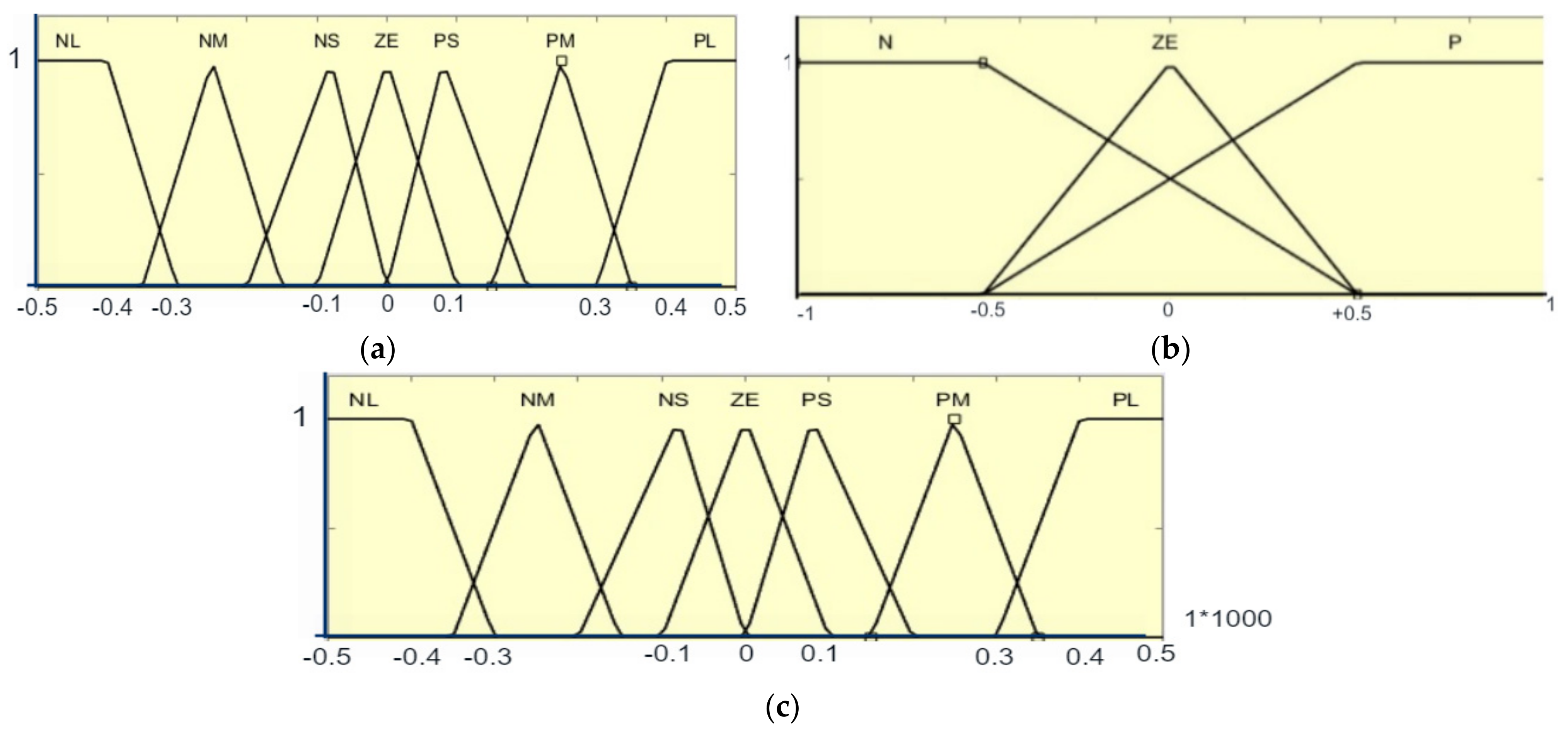
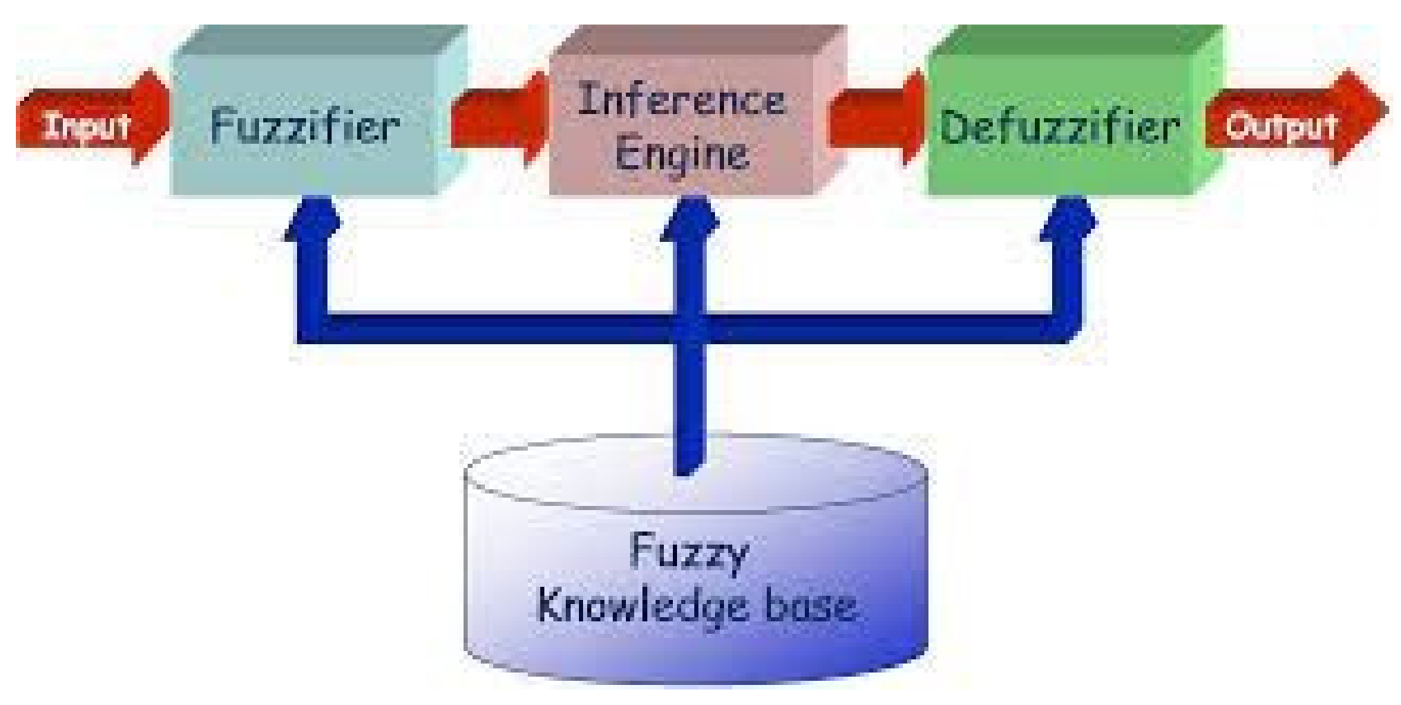
4.1. Review of Fuzzy Logic

Fuzzy logic is a technique of reasoning that is similar to the process of human reason. Fuzzy logic is a type of many-valued logic where the true value of variables may be any real value between 0 and 1. It is used to handle the partial truth concept, where the truth value may range between fully true and fully false. Fuzzy logic has four chief portions, which are introduced below [29].
Rule base consists of the rules set and the IF-THEN conditions provided by the specialists to govern the decision-making system with linguistic information. Recent advances in fuzzy logic have led to the construction of various effective approaches for the design and tuning of the fuzzy control laws. Most of the progresses decrease the fuzzy rules number.
Fuzzification is applied to convert the inputs, i.e., crisp numbers, into fuzzy sets. Crisp inputs are fundamentally the exact inputs measured by the sensors and passed into the control system for the process.
Inference engine determines the matching degree of current fuzzy input with respect to the rules and decides which rules are fired based on the input field. Then, the fired rules are mixed to establish the control inputs.
Defuzzification is employed to convert the fuzzy sets attained by the inference engine into the crisp value. There are various defuzzification approaches available. The centroid technique is one of the commonly applied defuzzification methods, and it is used in this paper.
All of the above items are shown in Figure 4 [30].

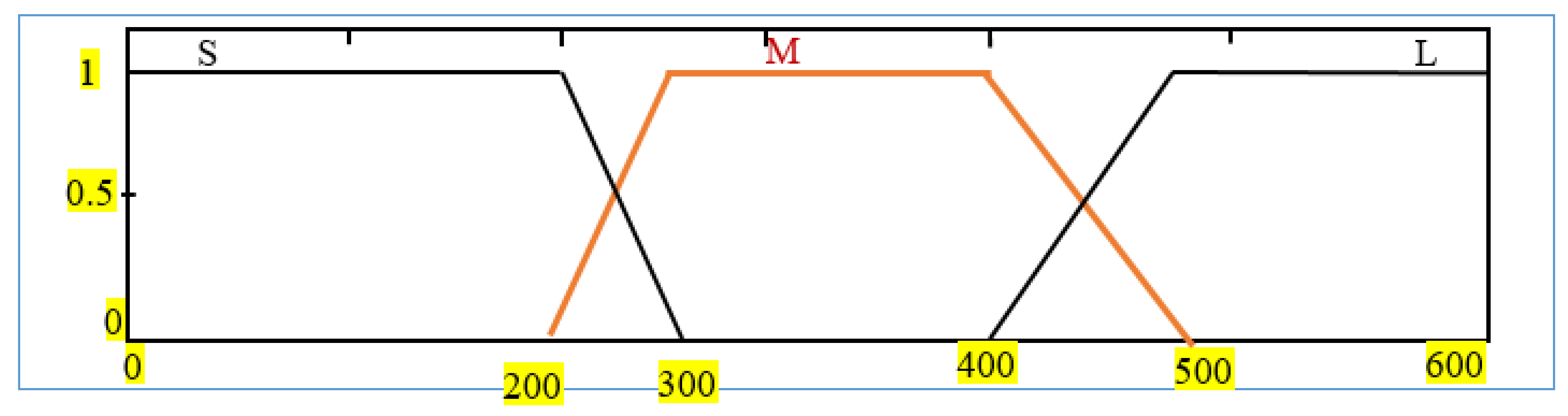
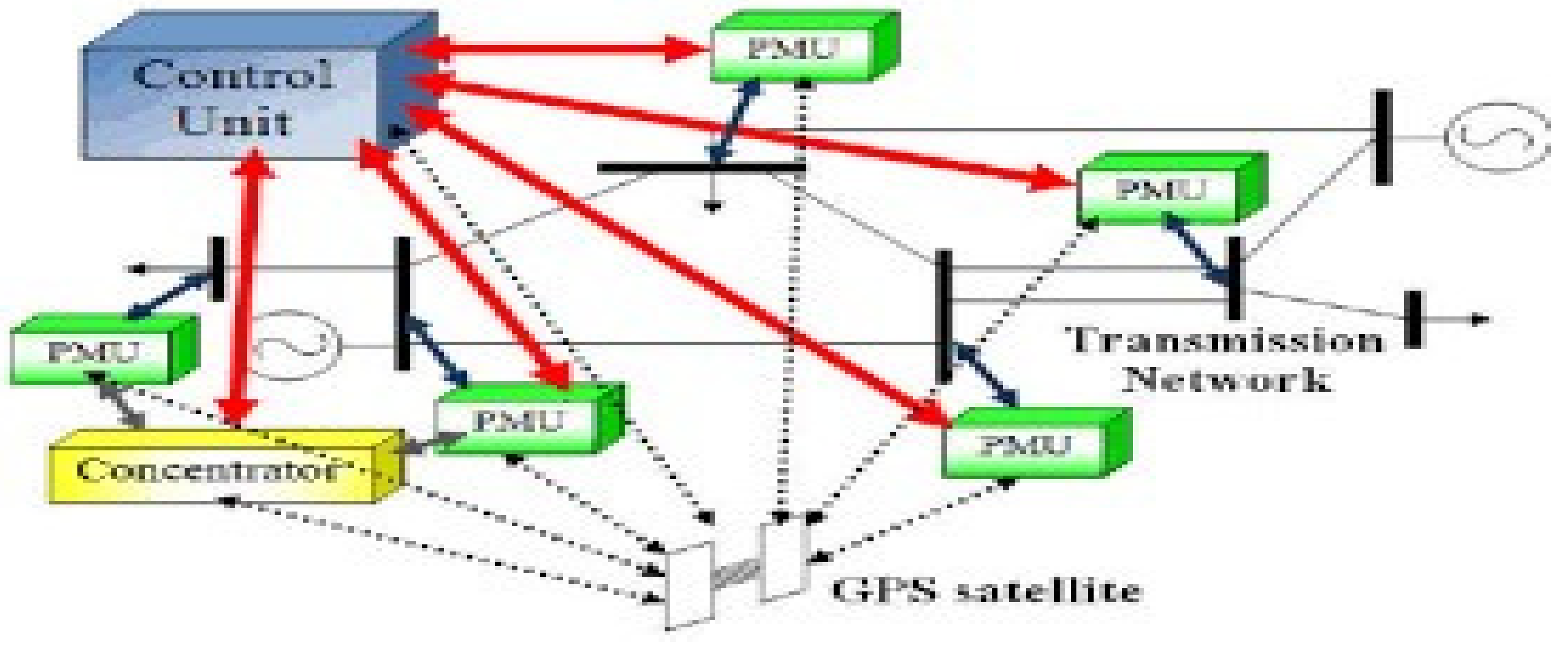
4.2. Review on Wide-Area Measurement Systems

By merging the abilities of telecommunication structures, digital measuring devices, and control laws, WAMS enables the monitoring, protection, and control of a smart grid over a wide area. In general, WAMS consists of three subsystems: measurement, telecommunication, and processing. The system contains several PMUs and phase data controllers (PDCs) linked by high-speed telecommunications networks, as demonstrated in Figure 5 [31].

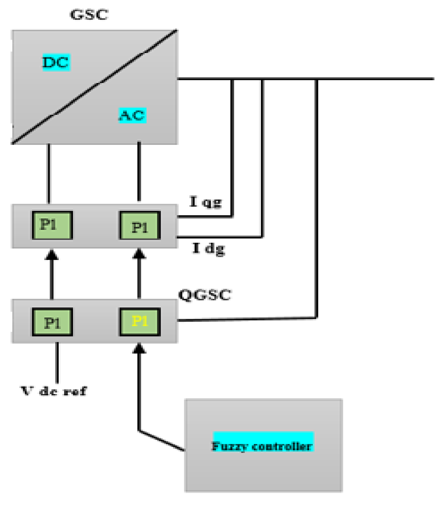
4.3. Fuzzy Controller Based on Wide-Area Measurement System

In order to evaluate the efficacy of the new method on the auxiliary wide-area fuzzy logic controller, we used the IEEE second benchmark model, modified by the inclusion of DFIG wind farms, as shown in Figure 1.
Figure 6 indicates the location of the WAMS controller. Due to the large distance of synchronous generators from wind farms, which are usually offshore, a PMU is used to measure the inputs of the fuzzy system. SSR damping is attained by adding the fuzzy controller as a supplementary signal at the stator voltage loop of the grid-side converter (GSC) of doubly fed induction generator (DFIG) wind farms. The input signals of this controller are the angular velocity and its variations in synchronous generators, which have four fuzzy inputs. One of the important items in control design is selecting the correct control input, as shown in Figure 2. In this study, the angular velocity of synchronous generators ( w ) and voltage across the series compensation ( V c ) were studied, and the optimum control signal was identified via residue analysis, clarified in the simulations.
The fuzzy control output, after being converted to a crisp number obtained by the center of gravity method, is applied to the voltage control loop of the GSC. The membership functions for the fuzzy controller’s inputs and output are obtained, as represented in Figure 7. The employed fuzzy rules are of the Mamdani type, as shown in Table 1. Notably, the Mamdani rules used in this research were obtained by trial and error.
The rules in terms of input parameters, i.e., the angular velocity of synchronous generators and variations in the velocity, are outlined as shown in Table 1. According to Table 1, for instance, if w 1 is NS and dw 1 dt is N, then the output is NM.
In conclusion, the output of the fuzzy system must be converted to a crisp number. As mentioned, there are several defuzzification methods available. The centroid technique, one of the commonly applied defuzzification methods, was used in this research. In this method, the control signal is:
Δ U K = i = 1 n M i T i i = 1 n T i
In Equation (3), M i is the membership grade and T i is the membership function singleton position.

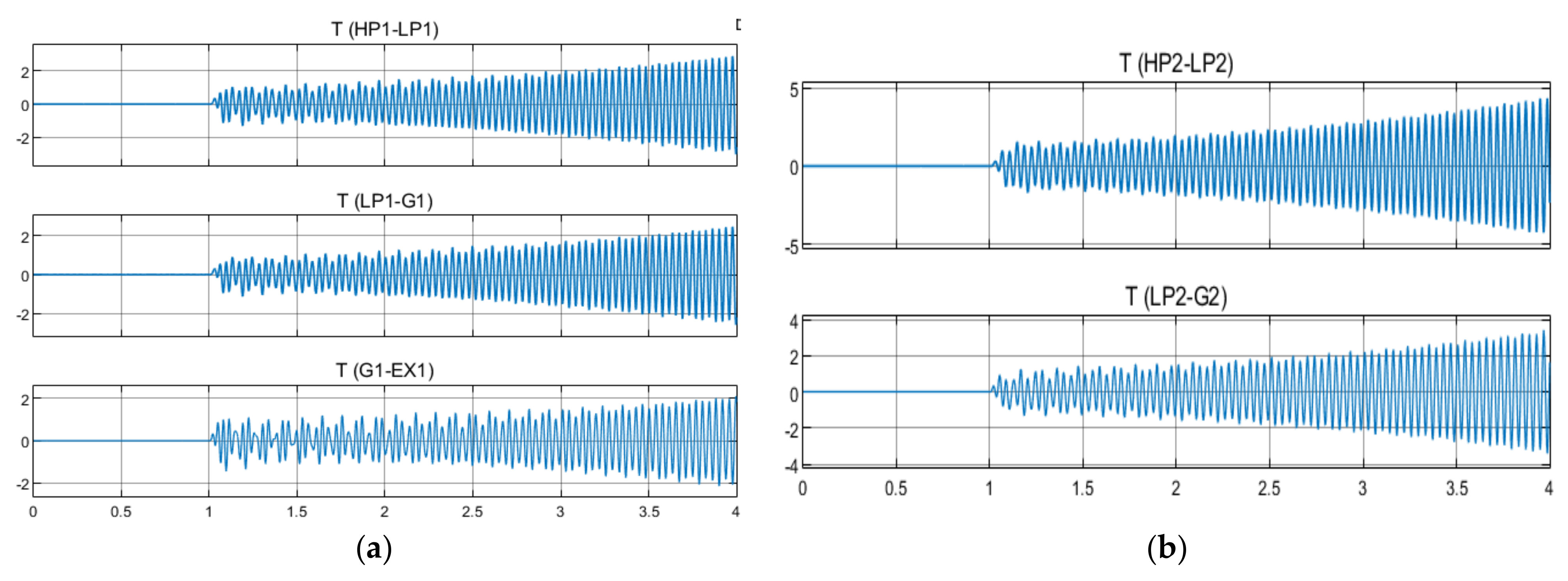
5. Simulation Result

A modified version of the IEEE second benchmark model including DFIG wind farms was employed to evaluate the suggested control input, and the MATLAB/Simulink R2020b toolbox was employed for the simulations of the considered system. In general, the simulation is performed in three parts. Initially, the system operates without auxiliary control at 85% compensation ( X c X l ), and at the moment t = 1 s, a three-phase fault occurs at bus j, which disappears at moment t = 1.0025 s. Figure 8 shows the torque of the steam turbine rotor in different parts, which is unstable at 85% of compensation. In this paper, the torque of the different parts of the steam turbine of both generators is presented in per unit.
In the following, the application of a fuzzy controller is designed based on a WAMS to dampen SSR, expressed in two ideal modes and in the presence of time delays.
As illustrated in Figure 7, SSR oscillations are damped by using a control input to the GSC stator voltage controller loop. As mentioned, residue analysis was applied to choose the input controller, angular velocity of synchronous generators (w), and voltage across series compensation ( V c ).
The transfer function G(s) is
G s = R i S λ i
where λ i is the eigenvalues and R i is the eigenvalues’ residues. Achieving the value of R i for the sub-synchronous mode corresponding to λ 1   and   2   in Table 1, the location of the controller, the angular velocity of synchronous generators, was selected as the input control signal.

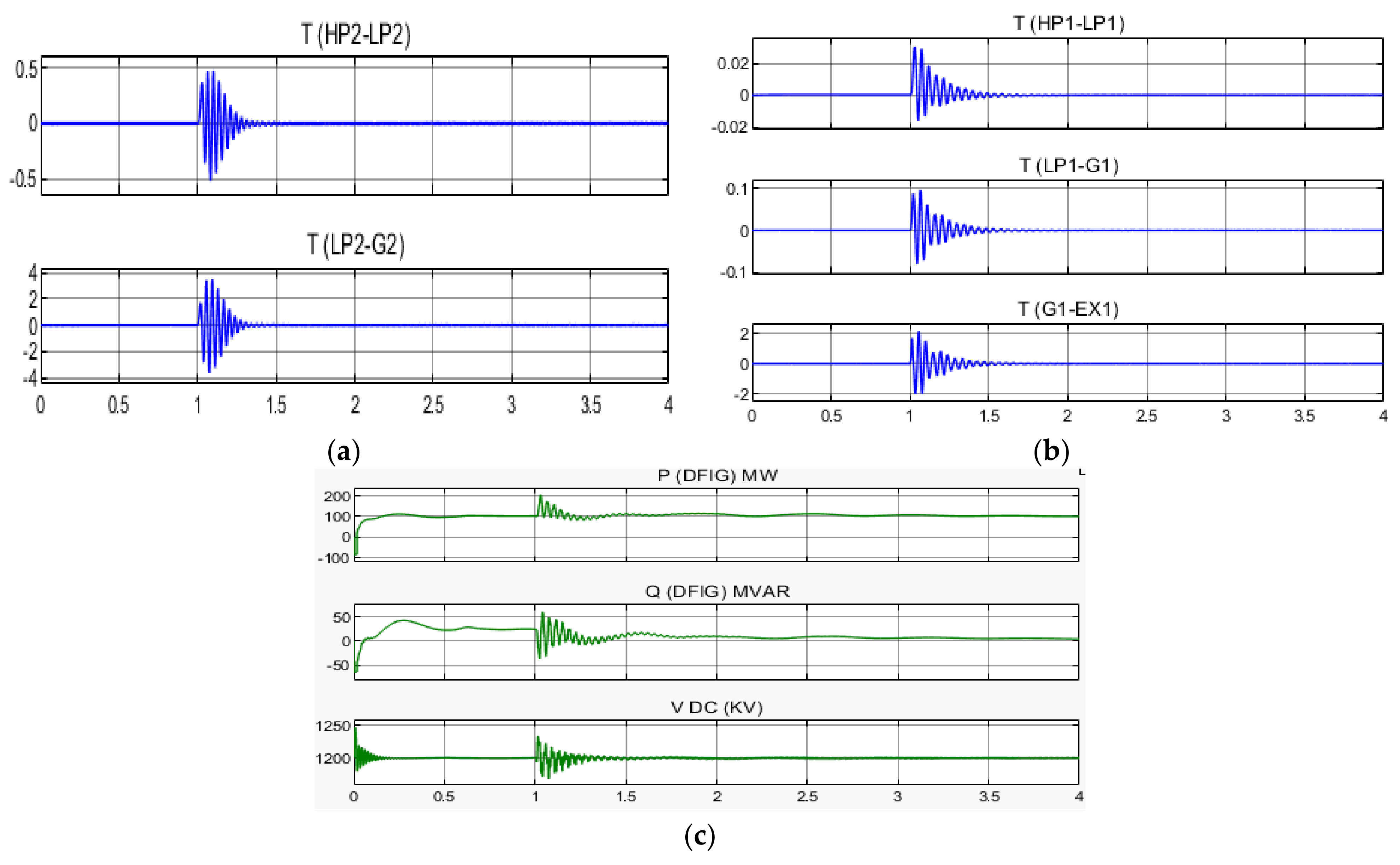
5.1. Wide-Area Fuzzy Controller without Time Delay

This part of the simulation shows the usage of fuzzy controllers in the studied system in the case where the delays produced by the measured PMU are ignored. As demonstrated in Figure 9, the SSR oscillations are damped by using a control signal to the stator voltage control loop in the GSC. With the 42 fuzzy rules in Table 1, and receiving the controller inputs, which are the same as the angular velocity, and variations in generators synchronous from the PMU, the functions of membership in Figure 7 will be satisfied by the SSR oscillations shown in Figure 9. According to Figure 9, in the condition where the compensation is 75% and the considered system is unstable, in the first second of simulations, a three-phase fault occurs at bus j, which disappears at moment t = 1.0025 s, and by applying a fuzzy controller, the oscillations are damped.

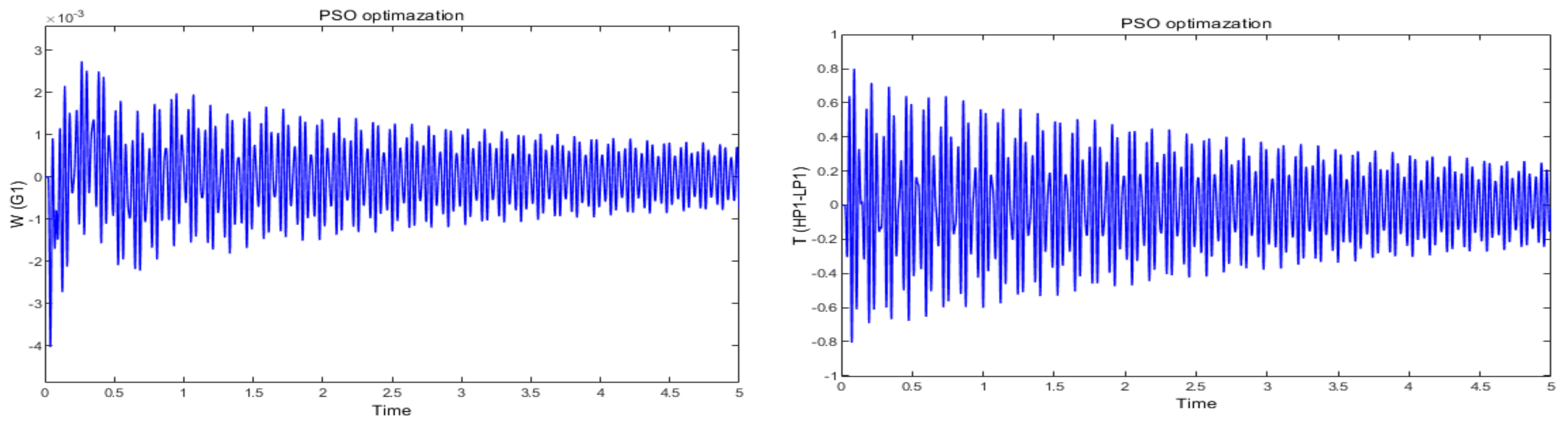
5.2. Wide-Area Fuzzy Controller with Time Delay

In the preceding subsection, the WAMS fuzzy control simulation was executed, in which the latencies due to the PMU measurements were ignored. In practice, the delays in sending of signals to the control input cannot be ignored because delays were inevitable in telecommunication systems. According to reference [31], these delays are classified as shown in Table 2. Therefore, if these delays are ignored, system instability occurs, as shown in Figure 10. That shows that the state the measurement signals employed for the wide-area fuzzy controller have a delay of 350 ms, and the control actions in the first second caused the instability of the system and failed to damp the system.
The membership functions associated with the fifth input are given in Figure 11. As shown, the amount of latency due to measuring PMU signals is divided into three intervals: small, medium, and large. Thus, three membership functions are introduced for the latency.
To apply the fuzzy inputs to the fuzzy system, the fuzzy rules of Table 1 were changed, the cause of which is well-illustrated in Figure 12.
Figure 12 shows w1 of G1 in three modes without delay (a), with medium delay (b), and with long delay (c); its dimensions can be in terms of per-unit.
Consider t = t1 as an instance. At t = t1, the primary signal, i.e., no-delay input of w1 is PL and (w1) is N, which, according to Table 3, will give the output value of fuzzy control equal to PM. At this moment, if the medium delay is (M: time delay 1), the fuzzy rule as w1 is PL and (w1) is P, and the system’s output must be ZE. In addition, at this point, the primary signal, i.e., no-delay input of w1 is NL and (w1) is P, which, according to Table 3, gives the output of fuzzy control signal equal to NM; at this moment, if the medium delay is (L: time delay 2), the fuzzy rule in the delay as w1 is ZE and (w1) is N, and the output of the system is ZE. Correspondingly, other modified fuzzy rules are shown in terms of time delay in Table 3.
By modifying the fuzzy rules that are modeled taking into account the time delays created by PMU measurements, the simulation results with two time delays of 400 milliseconds are presented in Figure 13. According to this figure, the fuzzy control input was able to dampen the fluctuations caused the SSR by considering the changes in fuzzy rules.
For comparing the results of the suggested technique with the optimization metaheuristic methods such as PSO and ICA, as mentioned in various references, the control structure of Figure 14 was considered. It was possible to optimize its parameters by optimizing the objective function Equation (4) with the PSO and ICA optimization methods.
Objective   Function = min f
f = t = 0 t = t sim t Δ ω 1 + Δ ω 2 dt
In Equation (4), t sim represents the simulation time, and ∆ω1 and ∆ω2 represent the angular velocity variations in the synchronous generators. To calculate the objective function, the time domain of the system model must be simulated with respect to all saturation constraints. The permissible limit k d 1 and k d 2 is between zero and one.
Table 4 shows the results of optimization with objective function (3) by both PSO and ICA methods. In addition, Figure 15 and Figure 16 show the angular velocity variations in generators with PSO and ICA algorithms.
In addition, a comparison of Figure 15 and Figure 16 with Figure 13 shows that the proposed WAMS-based fuzzy controller method is faster. Another important point in the method proposed in this paper is no need to adjust parameters at each level to compensate for transmission lines.

6. Conclusions

In this study, a new scheme for damping of subsynchronous resonance in power systems including utility DFIG wind farms linked to series capacitive compensated transmission lines was employed. The parameters of the additional fuzzy controller do not require adjustment at any percentage of compensation. In addition, the fuzzy controller enables a high-level compensation, namely 85%. Applying a WAMS that considers delays by the PMU measurement and the utility DFIG-based wind farms are the other main features of this controller. In addition, time delays due to the communication signals were shown to be important by using a WAMS. Ignoring the time delays causes instability of the system. The effectiveness of the planned controller in damping SSR fluctuations, compared to the methods that have been employed based on the optimization metaheuristic such as PSO and ICA, was demonstrated by MATLAB/Simulink simulations on the modified version of the IEEE second benchmark model including DFIG wind farms. Implementation of the proposed wide-area fuzzy control approach on a practical small-size DFIG wind farm for mitigation of the subsynchronous resonance can be investigated in upcoming research. Moreover, investigation into the subsynchronous resonance in power systems including DFIG and series single- and multi-type FACTS devices, instead of series capacitive compensators, will be studied in future works.

Author Contributions

Conceptualization, investigation, and writing—original draft preparation, Y.B. and S.J.; writing—review and editing and supervision, S.M., T.R., and A.B. All authors have read and agreed to the published version of the manuscript.

Funding

This research received no external funding.

Institutional Review Board Statement

Not applicable.

Informed Consent Statement

Not applicable.

Data Availability Statement

The data that support the findings of this study are available within the article.

Acknowledgments

This research was supported by Chiang Mai University.

Conflicts of Interest

The authors declare that they have no conflict of interest.

Appendix A. Systems Parameters

Transmission lines:
R L = 0.02   pu X T = 0.14   pu
X L = 0.05   pu X sys = 0.06   pu ,   transformer   ratio :   26 / 539   kV
Table A1. Shaft Parameters.
ParameterValueParameterValue
KGEN-EXC 2.82 pu/radHIP0.155589
KLPB-GEN70.858 pu/radHLPB0.884215
KHP-IP19.303 pu/radHEXC0.0342165
KIP-LPA34.929 pu/radHHP0.092897
KLPA-LPB52.038 pu/radHLPA0.858670
HGEN0.868495
Table A2. Parameters of DFIG- Based Wind Farms.
ParameterLower BoundUpper Bound
Base Power2 MW100 MW
Based voltage (VLL)690 V690 V
Xls0.092310.09231
Xlr0.099550.09955
Rs0.004880.00488
XM3.952793.95279
Xtg0.3 (0.189 mH)0.3 (0.189/50 mH)
DC-link base voltage1.2 KV1.2 KV
DC-link capacitor14 mF0.7 F

References

  1. Mohammadpour, H.A.; Santi, E. Modeling and control of gate-controlled series capacitor interfaced with a DFIG-based wind farm. IEEE Trans. Ind. Electron. 2014, 62, 1022–1033. [Google Scholar] [CrossRef]
  2. Xu, L.; Wang, Y. Dynamic modeling and control of DFIG-based wind turbines under unbalanced network conditions. IEEE Trans. Power Syst. 2007, 22, 314–323. [Google Scholar] [CrossRef]
  3. Hughes, F.M.; Anaya-Lara, O.; Jenkins, N.; Strbac, G. A power system stabilizer for DFIG-based wind generation. IEEE Trans. Power Syst. 2006, 21, 763–772. [Google Scholar] [CrossRef]
  4. Bialasiewicz, J.T.; Muljadi, E. The wind farm aggregation impact on power quality. In Proceedings of the 32nd Annual Conference on IEEE Industrial Electronics IECON 2006, Paris, France, 7–10 November 2006; pp. 4195–4200. [Google Scholar]
  5. Yan, G.; Wang, D.; Jia, Q.; Hu, W. Equivalent Modeling of Dfig-Based Wind Farms for Sub-Synchronous Resonance Analysis. Energies 2020, 13, 5426. [Google Scholar] [CrossRef]
  6. Fateh, D.; Birjandi, A.A.M.; Guerrero, J.M. A subsynchronous resonance prevention for DFIG-based wind farms. Turk. J. Electr. Eng. Comput. Sci. 2020, 28, 2670–2685. [Google Scholar] [CrossRef]
  7. Sewdien, V.; Wang, X.; Rueda Torres, J.; van der Meijden, M. Critical review of mitigation solutions for SSO in modern transmission grids. Energies 2020, 13, 3449. [Google Scholar] [CrossRef]
  8. Liu, H.; Xie, X.; Zhang, C.; Li, Y.; Liu, H.; Hu, Y. Quantitative SSR analysis of series-compensated DFIG-based wind farms using aggregated RLC circuit model. IEEE Trans. Power Syst. 2016, 32, 474–483. [Google Scholar] [CrossRef]
  9. Jiao, Y.; Li, F.; Dai, H.; Nian, H. Analysis and mitigation of sub-synchronous resonance for doubly fed induction generator under VSG control. Energies 2020, 13, 1582. [Google Scholar] [CrossRef] [Green Version]
  10. Naduvathuparambil, B.; Valenti, M.C.; Feliachi, A. Communication delays in wide-area measurement systems; Cat. No. 02EX540. In Proceedings of the IEEE Thirty-Fourth Southeastern Symposium on System Theory, Huntsville, AL, USA, 19 March 2002; pp. 118–122. [Google Scholar]
  11. Mohammadpour, H.A.; Santi, E. Analysis of sub-synchronous resonance (SSR) in doubly-fed induction generator (DFIG)-based wind farms. Synth. Lect. Power Electron. 2015, 5, 58–64. [Google Scholar] [CrossRef]
  12. Wang, L.; Xie, X.; Jiang, Q.; Liu, H.; Li, Y.; Liu, H. Investigation of SSR in practical DFIG-based wind farms connected to a series-compensated power system. IEEE Trans. Power Syst. 2018, 30, 2772–2780. [Google Scholar] [CrossRef]
  13. Alatar, F.; Mehrizi-Sani, A. Frequency scan–based mitigation approach of subsynchronous control interaction in type-3 wind turbines. Energies 2021, 14, 4626. [Google Scholar] [CrossRef]
  14. Vajpayee, S.; Panda, N.R.; Behera, P.; Swain, S.C. Implementation of PLL algorithm in DFIG based wind turbine connected to utility grid. In Proceedings of the IEEE 2020 Second International Conference on Inventive Research in Computing Applications (ICIRCA), Coimbatore, India, 15–17 July 2020; pp. 549–553. [Google Scholar]
  15. Musarrat, M.N.; Fekih, A.; Islam, M.R. An improved fault ride through scheme and control strategy for DFIG-based wind energy systems. IEEE Trans. Appl. Supercond. 2021, 31, 5401906. [Google Scholar] [CrossRef]
  16. Qiu, M.; Su, H.; Chen, M.; Ming, Z.; Yang, L.T. Balance of security strength and energy for a PMU monitoring system in smart grid. Commun. Protoc. Algorithms Smart Grid 2012, 50, 142–149. [Google Scholar] [CrossRef]
  17. Joint Working Group from the CIGRE Study Committees. Challenges with Series Compensation Applications in Power Systems when Overcompensating Lines. Electra, April 2021. Available online: https://electra.cigre.org/315-april-2021(accessed on 25 July 2021).
  18. Impram, S.; Nese, S.V.; Oral, B. Challenges of renewable energy penetration on power system flexibility: A survey. Energy Strategy Rev. 2020, 31, 100539. [Google Scholar] [CrossRef]
  19. Zhang, J.; Li, H.; Chen, D.; Xu, B.; Mahmud, M.A. Flexibility assessment of a hybrid power system: Hydroelectric units in balancing the injection of wind power. Renew. Energy 2021, 171, 1313–1326. [Google Scholar] [CrossRef]
  20. Fan, L.; Miao, Z. Mitigating SSR using DFIG-based wind generation. IEEE Trans. Sustain. Energy 2012, 3, 349–358. [Google Scholar] [CrossRef]
  21. Mohammadpour, H.A.; Ghaderi, A.; Mohammadpour, H.; Santi, E. SSR damping in wind farms using observed-state feedback control of DFIG converters. Electr. Power Syst. Res. 2015, 123, 57–66. [Google Scholar] [CrossRef]
  22. Din, Z.; Zhang, J.; Bassi, H.; Rawa, M.; Song, Y. Impact of phase locked loop with different types and control dynamics on resonance of DFIG system. Energies 2020, 13, 1039. [Google Scholar] [CrossRef] [Green Version]
  23. Zhang, X.; Xie, X.; Liu, H.; Liu, H.; Li, Y.; Zhang, C. Mitigation of sub-synchronous control interaction in wind power systems with GA-SA tuned damping controller. IFAC-PapersOnLine 2017, 50, 8740–8745. [Google Scholar] [CrossRef]
  24. Wang, Y.; Wu, Q.; Yang, R.; Tao, G.; Liu, Z. H∞ current damping control of DFIG based wind farm for sub-synchronous control interaction mitigation. Int. J. Electr. Power Energy Syst. 2018, 98, 509–519. [Google Scholar] [CrossRef]
  25. Liu, H.; Xie, X.; Li, Y.; Liu, H.; Hu, Y. Mitigation of SSR by embedding subsynchronous notch filters into DFIG converter controllers. IET Gener. Transm. Distrib. 2017, 11, 2888–2896. [Google Scholar] [CrossRef]
  26. Yan, X.; Chang, W.; Cui, S.; Rassol, A.; Jia, J.; Sun, Y. Recurrence of sub-synchronous oscillation accident of hornsea wind farm in UK and its suppression strategy. Energies 2021, 14, 7685. [Google Scholar] [CrossRef]
  27. Irwin, G.D.; Jindal, A.K.; Isaacs, A.L. Sub-synchronous control interactions between type 3 wind turbines and series compensated AC transmission systems. In Proceedings of the 2011 IEEE Power and Energy Society General Meeting, Detroit, MI, USA, 24–28 July 2011; pp. 1–6. [Google Scholar]
  28. Raju, D.K.; Umre, B.S.; Junghare, A.S.; Babu, B.C. Mitigation of subsynchronous resonance with fractional-order PI based UPFC controller. Mech. Syst. Signal. Process. 2017, 85, 698–715. [Google Scholar] [CrossRef]
  29. Raju, D.K.; Umre, B.S.; Junghare, A.S.; Thakre, M.P.; Motamarri, R.; Somu, C. Fractional-order PI based STATCOM and UPFC controller to diminish subsynchronous resonance. SpringerPlus 2016, 5, 1599. [Google Scholar]
  30. Raju, D.K.; Umre, B.S.; Junghare, A.S.; Babu, B.C. Improved control strategy for subsynchronous resonance mitigation with fractional-order pi controller. Int. J. Emerg. Electr. Power Syst. 2016, 17, 683–692. [Google Scholar] [CrossRef]
  31. Dhenuvakonda, K.R.; Singh, A.R.; Thakre, M.P.; Umre, B.S.; Kumar, A.; Bansal, R.C. Effect of SSSC-based SSR controller on the performance of distance relay and adaptive approach using synchronized measurement. Int. Trans. Electr. Energy Syst. 2018, 28, e2620. [Google Scholar] [CrossRef] [Green Version]
Figure 1. Single-line model of the studied system.
Energies 15 01787 g001
Figure 2. Single-line model of DFIG.
Energies 15 01787 g002
Figure 3. The structure of RSC and GSC controllers.
Energies 15 01787 g003
Figure 4. Fuzzy logic system.
Energies 15 01787 g004
Figure 5. The hierarchical structure of a WAMS.
Energies 15 01787 g005
Figure 6. Location of fuzzy controller in the GSC convertor.
Energies 15 01787 g006
Figure 7. Inputs and output membership functions: (a) Angular velocity of generators, (b) variations of angular velocity of generators, (c) output of fuzzy controller. NL, negative large; NM, negative medium; Z, zero; PM, positive medium; PL, positive large; N, negative; P, positive.
Energies 15 01787 g007
Figure 8. (a) Torque T (HP1-LP1), T (LP1-G1), and T (G1-EX1) in the steam turbine of G1; (b) torque T (HP2-LP2) and T (LP2-G2) in the steam turbine of G2 without damping.
Energies 15 01787 g008
Figure 9. Damping of SSR oscillation in synchronous generation and DFIG with wide-area fuzzy controller without time delay. (a): turbine torque of second synchronous generation, (b): turbine torque of first synchronous generation, (c): VDC, Q, and P of DFIG.
Energies 15 01787 g009
Figure 10. SSR oscillation in synchronous generation with a wide-area fuzzy controller have a delay of 350   ms .
Energies 15 01787 g010
Figure 11. Membership functions of the time delay. S, small; M, medium; L, large.
Energies 15 01787 g011
Figure 12. Time delay signal of w1, (a): PMU location without delay; (b): GSC location with medium time delay; (c): GSC location with large time delay.
Energies 15 01787 g012
Figure 13. Damping of SSR oscillation in synchronous generation and DFIG with wide-area fuzzy controller with time delay. (a): turbine torque of first synchronous generation, (b): turbine torque of second synchronous generation, (c): VDC, Q, and P of DFIG.
Energies 15 01787 g013
Figure 14. Structure of damping controller with optimization methods.
Energies 15 01787 g014
Figure 15. Damping of SSR with ICA method (synchronous generations and, turbine torque).
Energies 15 01787 g015
Figure 16. Damping of SSR with PSO method (synchronous generations and, turbine torque).
Energies 15 01787 g016
Table 1. Fuzzy rules according to fuzzy system inputs and output (a) G1 and (b) G2.
AB
d w 1 d t P NZE d w 2 d t P NZE
w 1 w 2
G1PLPLPMPLG2PLPLPMPL
PMPLPSPMPMPLPSPM
PSPMZEPSPSPMZEPS
ZEPMNMZEZEPMNMZE
NSZENMNSNSZENMNS
NMNSNLNMNMNSNLNM
NLNMNLNLNLNMNLNL
Table 2. An example of telecommunications data delays.
Communication Data DelaysAssociated Delay (ms)
Telephone Lines200–350
Satellite link500–700
Table 3. Rule based on wide-area fuzzy controller with time delay.
Time Delay d w 1 d t PLPMPSZENSNMNL
W 1
MPPMNLPLPMPMNMPM
NNLZEPMNLNSNMPS
ZENSPSNMZEPLNMNL
LPZEPMPLNMNLNMPM
NPLZENMNMPMPSNM
ZEPSNLZEPLNMZEPL
Table 4. The values of coefficients k d 1 , and k d 2 .
Optimization Methods k d 1 k d 2
PSO0.640.38
ICA0.720.57
Publisher’s Note: MDPI stays neutral with regard to jurisdictional claims in published maps and institutional affiliations.

