1. Introduction
Increased power demand, along with the worldwide push for clean energy production, has led to increasing interest in electric power generation using renewable energy sources, especially wind power. DFIG-based, variable-speed wind turbines are the most installed wind generation systems in wind farms. The increased integration of wind farms into the power grid has led to an increased requirement to transmit the generated power to the grid via transmission networks without congestion [
1]. Additionally, the need to lower the cost of power production has led to the requirement to increase the power transfer capability of existing transmission lines at the lowest possible cost [
2]. Series capacitive compensation of wind farms has emerged as the cost-effective approach to increase the power transfer capability of the transmission lines connecting wind farms to the grid [
3]. Though series compensation is a cost-efficient way to decrease the line reactance and improve the system stability and increase the transfer capacity for long transmission lines, series capacitors cause fluctuations with frequencies less than the nominal frequency of the network, known as sub-synchronous resonance (SSR) [
4]. Additionally, the increased penetration of DFIG-based wind farms has led to the installation of new substations along series-compensated lines. However, the installation of new substations along existing series-compensated transmission lines can lead to overcompensated lines (lines with effective series reactance that become capacitive) and further aggravate the SSR problem [
5].
The SSR phenomenon is divided into the induction generator effect (IGE) and torsional interaction (TI) in wind farms interfaced with series-compensated transmission lines. In reality, the SSR phenomenon in induction machines is the IGE due to wind generators; the frequency torsional modes can be as little as 1–3 Hz. On the other hand, torsional interaction mode must have a frequency of 57–59 Hz [
6]. So far, a large number of studies have been conducted in the field of SSR. Some focused on damping SSR oscillations using an additional controller in the rotor-side converter (RSC) and grid-side converter (GSC) of the DFIG-based wind farm, whereas others emphasized using FACTS devices. For instance, the rotor velocity was used in SSR mitigation control in [
7]. Varma et al. explored TCSC and SVC’s capability in SSR mitigation in [
8]. In [
9] investigated SSR in series-compensated, fixed-speed wind generation systems with self-excited, double-cage induction generators. That study showed that the output power from wind farms is inversely proportional to the power system damping. However, most existing wind farms employ DFIG-based, variable-speed wind turbines due to their advantages and ease of control. The study reported in [
10] did consider DFIG-based wind turbines; however, only time-domain simulations were considered. No small-signal (eigenvalue) analysis was carried out to understand the damping of modal oscillations related to SSR. The modeling and stability analysis of a DFIG-based wind farm interfaced with series compensation was reported in [
11]. The impact of parameters, such as wind speed, compensation level, and current controller parameters, on system damping under sub-synchronous frequency were studied in [
12]. However, the study did not differentiate between the two SSR phenomena and overlooked the relationship between the turbine parameters and torsional oscillation modes.
In [
13], the IEEE first benchmark model was adopted for the study, and the superiority of the FOPI-based UPFC controller over the PI-based UPFC controller was discussed by comparing the results with various performance indices. A fractional-order PI controller was proposed in [
14] to mitigate the sub-synchronous oscillations in the turbine-generator shaft resulting from the sub-synchronous resonance (SSR) stemming from the FACTS devices. In [
15], a robust fractional-order PI (FOPI) controller was proposed to decrease the sub-synchronous resonance (SSR) using a static synchronous series compensator (SSSC). The proposed controller was shown to reduce the sub-synchronous oscillations to 4%. In [
16], a new approach was proposed for mitigating the problems associated with distance protection by using the synchrophasor measurement. The entire simulation study was investigated using a 48-pulse SSSC and carried out with the Bergeron model of transmission line in PSCAD. However, Wide Area Monitoring Systems (WAMS) are predominantly used in modern power systems; since most wind farms are installed in remote locations far from the compensated power system and transmission lines [
17], which is important since the additional controller is for SSR attenuation in DFIG controllers, and this study used voltage and compensator capacitor voltage variations for additional controller inputs. In fact, the measurement of input quantities in WAMS was performed by using phasor measurements units (PMU), which are some of the main components of WAMS. However, the delay of measurement signals by the PMU should be considered in designing the controller as ignoring latency may lead to power system instability [
18].
This paper proposes a novel approach for mitigating sub-synchronous resonance (SSR) in DFIG-based wind farms installed in a microgrid with wide area monitoring system (WAMS). Its main contributions are as follows:
A WAMS-based Fuzzy controller design that takes into consideration communication time latencies resulting from PMU measurement signals.
A design that reduces sub-synchronous resonance for DFIG-based wind farms.
Performance analysis is carried out using both time-domain simulations and small signal analysis (eigenvalues).
The remainder of this paper is organized as follows.
Section 2 briefly describes the model of the wind power plant under consideration.
Section 3 briefly describes the SSR phenomenon in fixed series compensated DFIG.
Section 4 describes the proposed wide- area fuzzy logic controller (FLWADC).
Section 5 discusses the simulation results for the case study. Finally, some concluding remarks are given in
Section 6.
2. Dynamic Model of the System
Wind farms are typically modeled using the aggregation of several identical wind turbines.
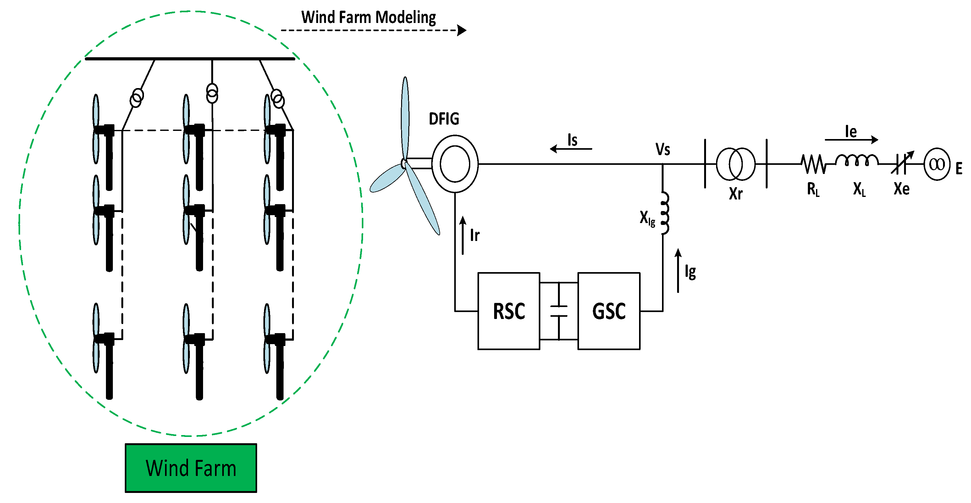
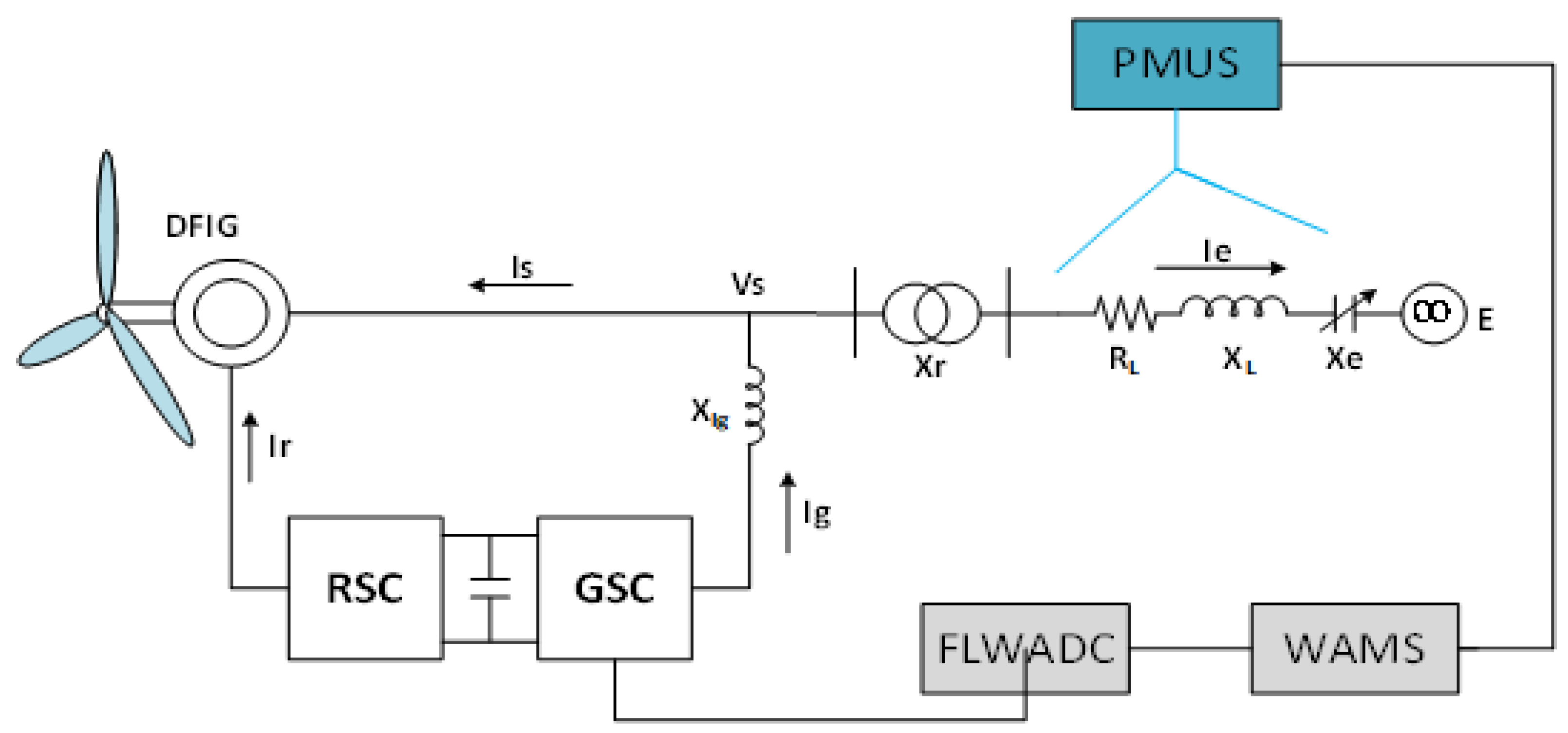
A single line diagram of a DFIG-based wind turbine is depicted in
Figure 1. [
12,
14,
15,
16,
17]. Here, Xr represents the transformer reactance, R
L, represents the transmission line resistance, X
L the transmission line reactance, X
C the fixed series capacitor, X
S the system’s impedance, whose data are given in the
Appendix A (
Table A1).
The dynamic model of each component depicted in the above single line diagram are briefly described below:
2.1. DFIG Model
The DFIG system includes an induction machine and a rotor-side converter (RSC) and a grid-side converter (GSC) connected back-to-back through a dc-link capacitor [
18,
19]. Assuming negligible magnetic saturation and
as the state vector and
as control input, the model of an induction machine synchronously rotating in a (dq0) reference frame can be represented as follows [
20]:
where:
where
is the base frequency. This latter is equal to the synchronous frequency and is considered to be equal to 314 rad/s per second.
is the angular frequency of the rotating frame dq.
is the stator resistance,
the rotor resistance,
the magnetic reactance,
the stator leakage reactance, and
the rotor leakage reactance.
, and
where the subscripts r and s stand for rotor and stator, respectively. The subscripts
d and
q stand for direct and quadrature component, respectively.
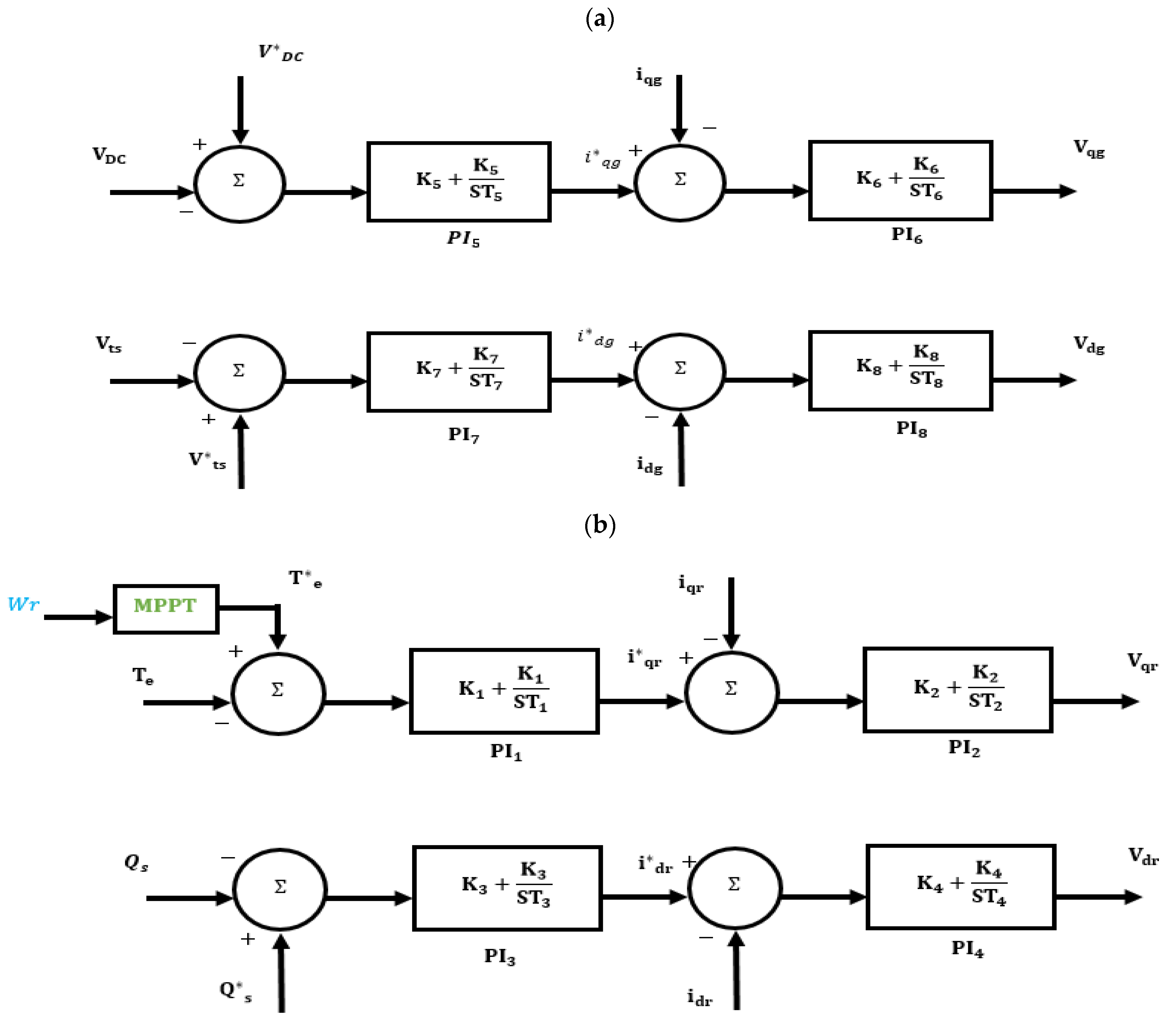
The RSC and GSC converters, along with their respective proportional integral (PI) controllers, are depicted in
Figure 2.
Note that the RSC control loops regulate the electromagnetic torque (d-axis loop) and the generator reactive power (q-axis loop), whereas the GSC control loops regulate the DC-link voltage (q-loop) and terminal voltage (d-loop) by providing necessary reactive power [
21].
A look-up table-based on Maximum Power Point Tracking (MPPT) is considered to generate the necessary reference torque to ensure maximum power extraction from the wind, as depicted in
Table 1.
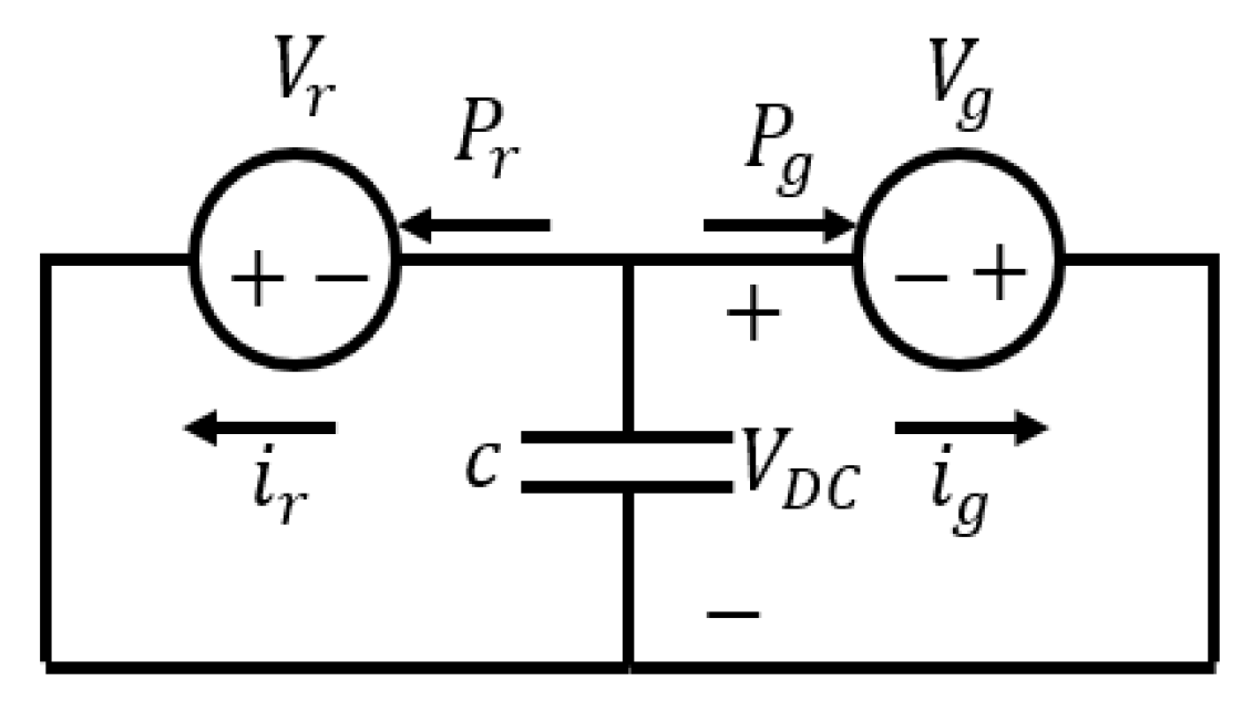
The DC-link capacitor connecting the GSC and RSC (
Figure 3) can be modeled using the following first order differential equations:
where
is the true power of the RSC converter, and
is the active power of the GSC.
, and
are the output voltages of the two converters RSC and GSC, respectively [
22].
2.2. Model of the Wind Turbine’s Shaft
The wind turbine’s shaft is modeled as follows [
23]:
where
represents the wind turbine’s speed,
depicts the speed of the generator rotor, and
is the torsional torque.
is the torque generated by the wind, and
is the electric torque of the generator.
2.3. Model of the Capacitive Series-Compensated Power Line
The transmission line, along with its capacitors, is modeled as follows [
24]:
where
and
are the series capacitor voltages and currents in the qd0 frame, respectively.
,
,
, and
are the stator and the infinite bus voltages in the qd0 reference frame, respectively.
3. SSR and its Methods for Analysis
3.1. Definition of SSR
The SSR phenomenon is the state in which the wind exchanges in one or more natural frequencies energy with the electrical grid. If not prevented, this phenomenon causes damages. The SSR phenomenon is due to two inductive generating effects and the torsional interference effect. In a network with capacitive series compensation, the network has a natural frequency that is calculated by Equation (14); in this relation, the resonant frequency
is called sub-synchronous frequency.
is synchronous frequency, and
is the total reactance of the inductor, transformers, and inductor in
Figure 1.
is the reactance of a series capacitor, which is a percentage of the reactance.
is called the compensation percentage. Due to frequency
, slip
is introduced according to Equation (15) [
14,
19].
Since is negative, the equivalent resistance of the rotor at the sub-synchronous frequency () is negative. In other words, is negative when the amplitude of this resistor is more than the sum of the network and armature resistors.
As shown in the second part of Equation (16), the current of the whole system has an exponential function with a positive power. A sub-synchronous component with a frequency of
appears in the currents and voltages of the stator and mains circuit with the existence of a capacitive series compensator. The complementary frequency of this component appears as IGE in the rotor current [
18].
The torsional mode is the frequency between the two masses of the rotor shaft with a complementary frequency of the network (
) equal to or close to it. The torsional interaction (TI) effect occurs when the frequency of the torsional mode between the two masses of the rotor shaft with a complementary frequency of the network (
) is equal or close to each other. The frequency of the torsional modes of their rotors is low due to the low stiffness of the rotor shafts of wind farms. Thus, SSR occurs in wind power due to the effect of torsional interaction (TI). Thus, there is a need for a very high level of compensation [
25]. In addition, the probability of its occurrence is very low since it requires very high compensation [
25].
3.2. Small-Signal Analysis (System Eigenvalues)
The general state space of the network was modeled around its equilibrium point, depending on wind speed and level of compensation of the capacitor of series, using the linmod command obtained in MATLAB software. In this regard, 20 eigenvalues were obtained from the general state space of the network [
26], which were four eigenvalues for the induction machine, three for the shaft system, eight for the RSC and GSR of the DFIG, four for the transmission line with series capacitor, and one for the DC-link which formed the 20th degree model.
Table 2 indicates the system eigenvalues for a compensation level of 70% and wind speed of 8 m/s.
3.3. Review of Fuzzy System
Fuzzy logic is considered as a method for reasoning which is similar to the way human’s reason. The fuzzy logic approach mimics the human decision-making method in which all possible intermediate states between the digital values of “yes” and “no” are considered. Fuzzy logic has four main parts, as discussed below [
27].
Rule base: This section includes all of the rules and conditions which are specified as “if then” by an expert and are able to control the decisions of a “decision-making system”. Based on the new methods in fuzzy theory, it is possible to adjust and reduce the rules and regulations so that the best results can be obtained with the fewest rules.
Fuzzifire: In the fuzzy step, the inputs are converted to fuzzy information. In other words, the numbers and information to be processed become fuzzy sets and numbers. Input data are measured, for example, by sensors in a control system, which are modified and prepared for fuzzy logic processing.
Inference engine: In this section, the degree of compliance of the fuzzy input with the basic rules is determined. In this way, different decisions are generated as a result of the fuzzy inference engine based on the percentage of compliance.
Defuzzifire: In the last step, the results of fuzzy inference, which are fuzzy sets, are converted into quantitative data. At this stage, you choose the best decision according to the outputs, which include different decisions with different percentages of compliance. This choice is normally based on the maximum degree of compliance.
4. Proposed Wide-Area Fuzzy Logic Controller (WAFLC)
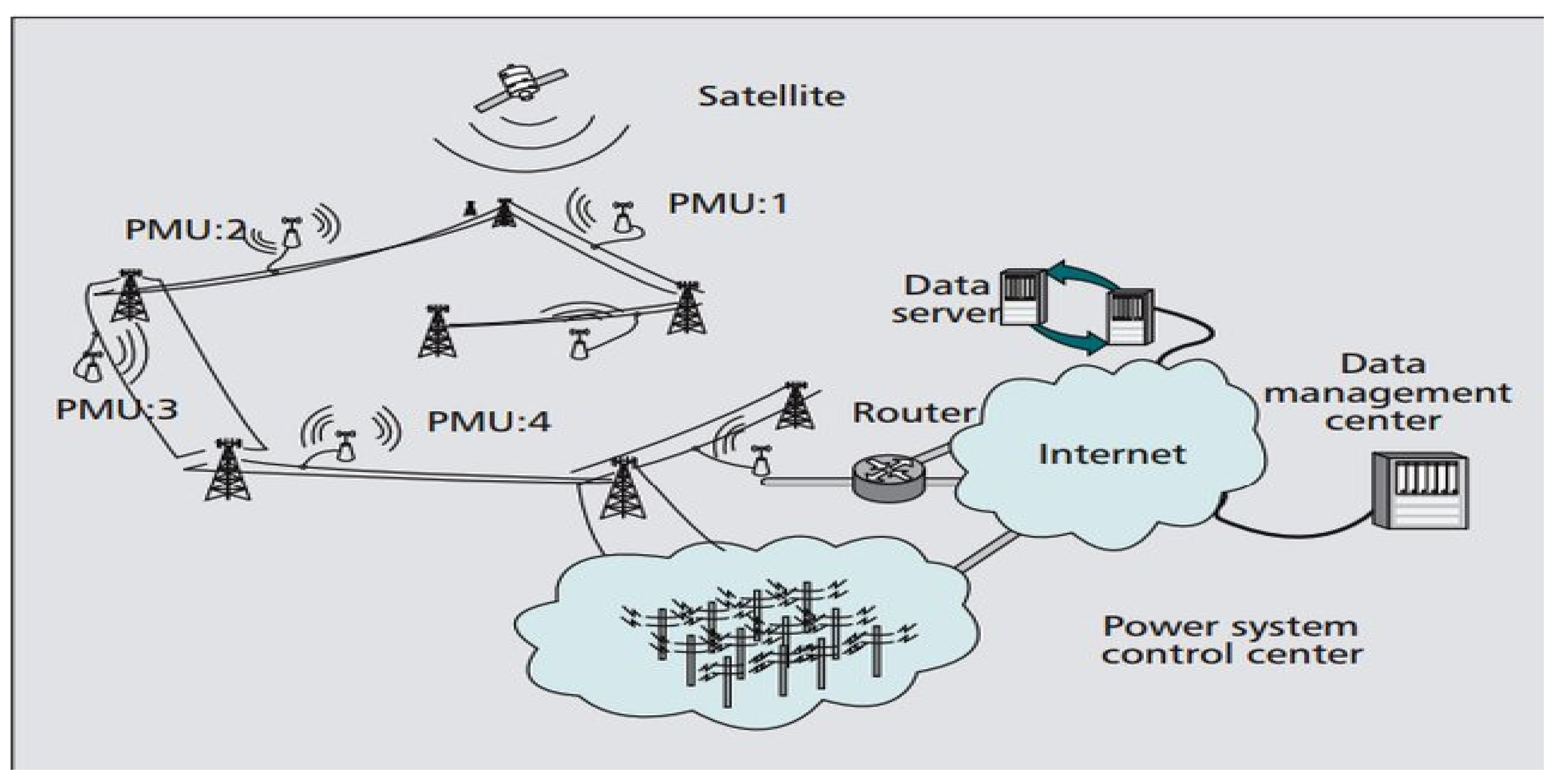
By combining the capabilities of telecommunication systems and digital measuring devices and controllers, wide-area measurement systems (WAMSs) enable the monitoring, protection, and control of the increasingly complex large power systems. In general, WAMSs consist of three sub-systems, including measurement, telecommunication, and control. The system consists of several phasor measurement units (PMUs) and one or more power distribution systems (PDCs) connected by a high-speed telecommunications network, as shown in
Figure 4 [
28].
In this study, a WAMS was used to design a fuzzy controller. For this purpose, the PMU, which is one of the main components of WAMSs, was used to measure the compensating voltage of the transmission line series and its changes and was applied to the input of the fuzzy controller. One of the most important items in controller design is choosing the right input signal for the controller, as shown in
Figure 2. In this paper, rotor speed (
) and voltage across the series compensation (
) were examined, and the optimum input control signal was identified with residue-based analysis, explained in the time-domain simulation results section. Mamdani was used as the fuzzy inference motor. The damping of SSR was achieved by applying an additional controller to the GSC, as well as the stable voltage control loop.
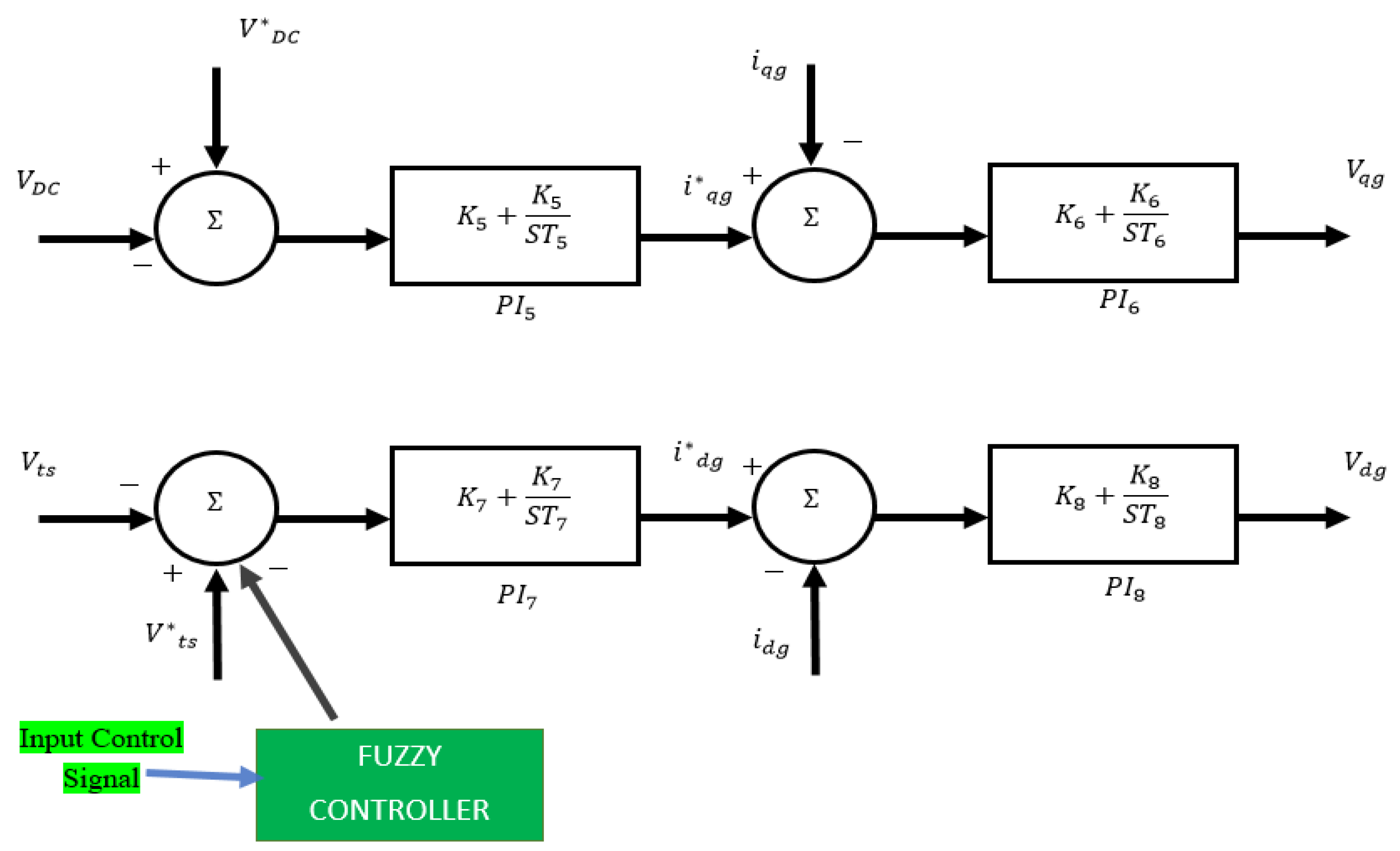
Figure 5 shows the IEEE first benchmark modified by a DFIG-based wind farm with a WAMS and its controller. In addition,
Figure 6 displays the location of the fuzzy controller located in the GSC stator voltage control loop. In fact, using the WAMS and considering the time delays caused by sending measurement signals to the controller are some of the innovations of this paper. Therefore, this paper, as mentioned in [
28], does not apply PLL for the WAMS, while PLL in [
29] was used in the design of the controller.
Figure 6 shows the location of the fuzzy controller, which was applied to the input of the stator voltage control loop of the GSC.
4.1. Fuzzification
Fuzzy controller input is the capacitive compensating voltage (
) of the transmission line series and its changes (
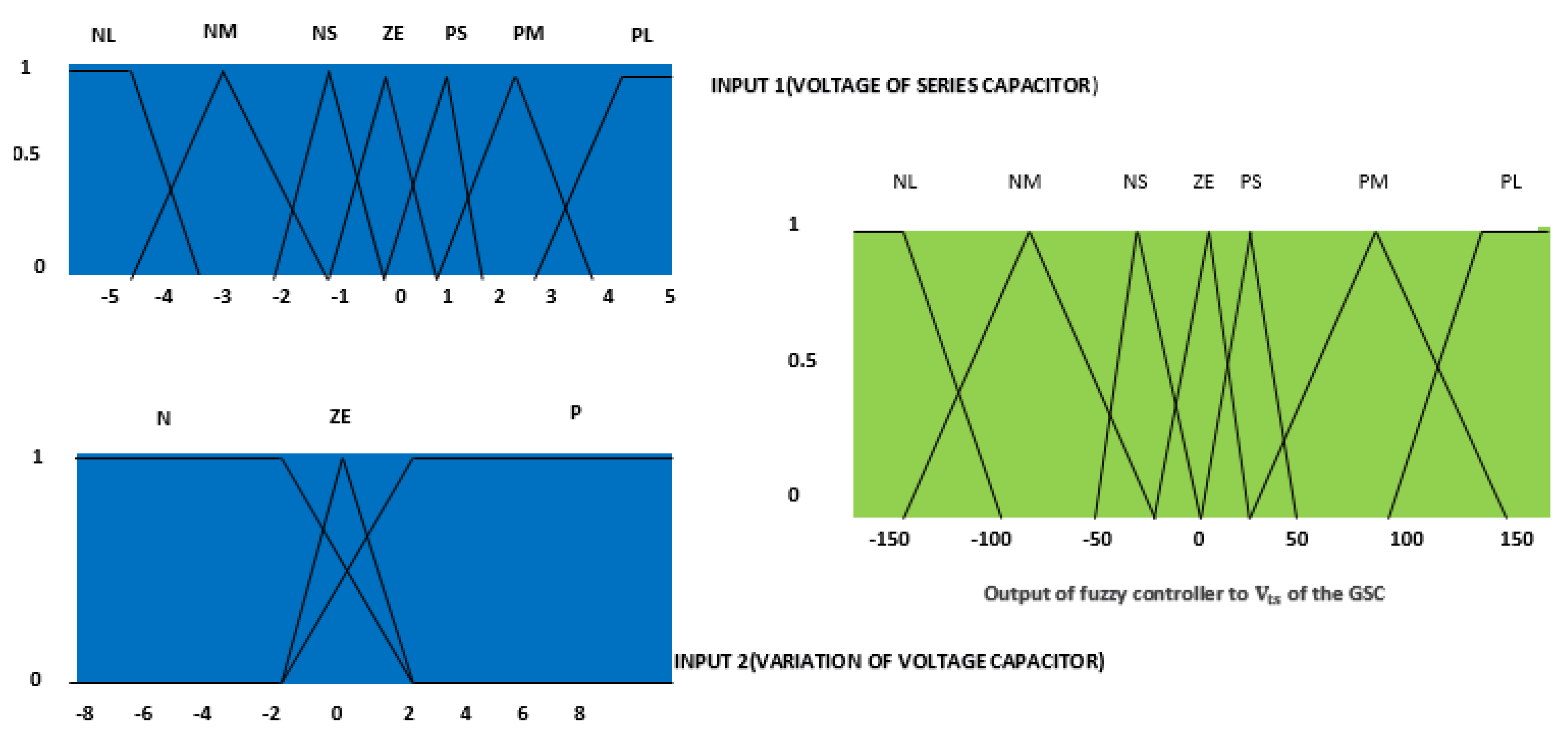
), the membership function of which is considered as follows based on the fuzzy rules.
Figure 7 displays the capacitor voltage with seven membership functions and its changes with three membership functions, as well as fuzzy controller output with seven membership functions, which is considered as the knowledge of an expert. As shown, the symbols were defined as negative large (NL), negative (NM), medium, negative small (NS), zero (ZE), positive small (PS), positive medium (PM), positive large (PL), negative (N), and positive (P).
4.2. Rule Base and Inference Engine
As mentioned, the fuzzy rules were based on Mamdani type, in the form of “if then” and in the form of 21 fuzzy relations according to the inputs and outputs of the fuzzy system, as shown in
Table 3. For instance, as shown in
Table 3, if
was NS and
was N, then the output was NM.
4.3. Defuzzification
Finally, the output of the fuzzy system was converted to a crisp number. In this study, the average center of gravity was used.
5. Time-Domain Simulation Results
An IEEE-first-benchmark-modified, DFIG-based wind farm system was used to evaluate the proposed controller, and MATLAB/Simulink software was applied for simulating the time of the studied system. As mentioned before, the percentage of compensation of the transmission line is considered as one of the influential factors in SSR fluctuations, which increases with the percentage of compensation of the system towards instability. The modes of the studied system were expressed by using the eigenvalues method in
Table 2, indicating that
λ1 and
λ2 were the oscillation modes of the system in the case where the compensation percentage was 25, 40, 60, and 75, as represented in
Table 4. In this oscillating mode, the resonance frequency was 37.56 Hz, and the SSR frequency was 22.44 Hz. The contents of Equation (17) indicate an increase in the percentage of compensation, causing the resistance of the whole system to be negative, leading to instability in the system.
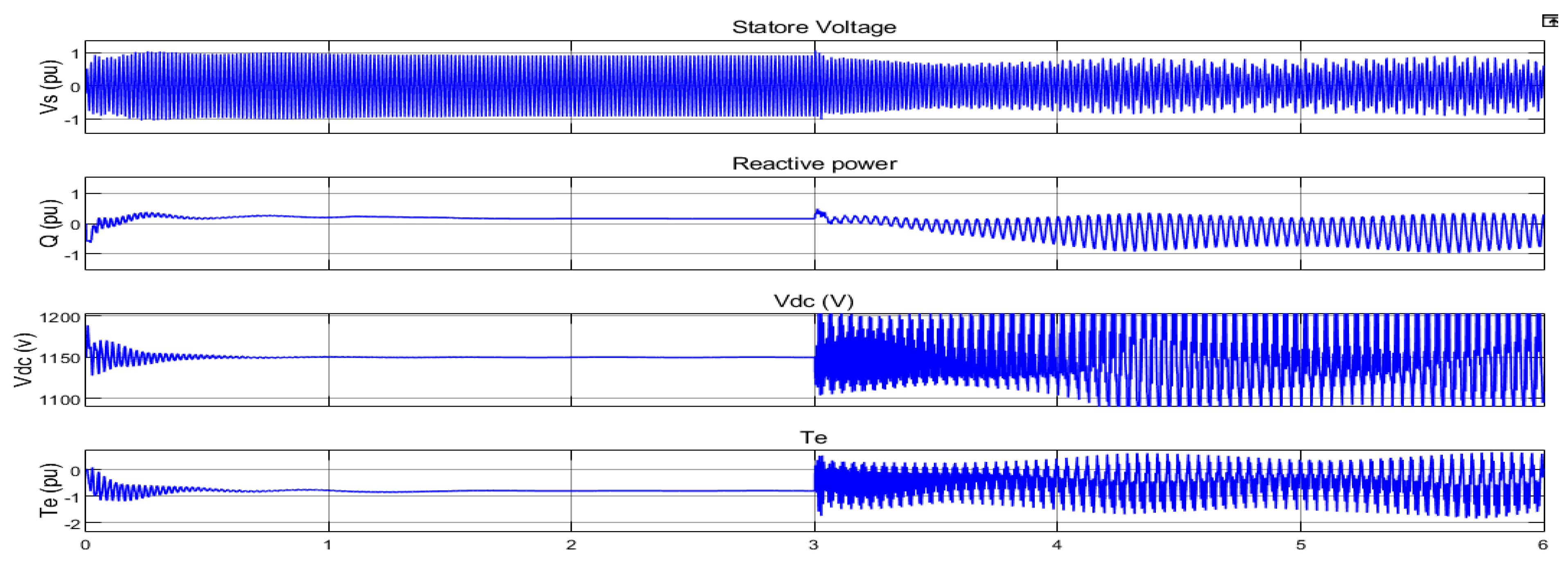
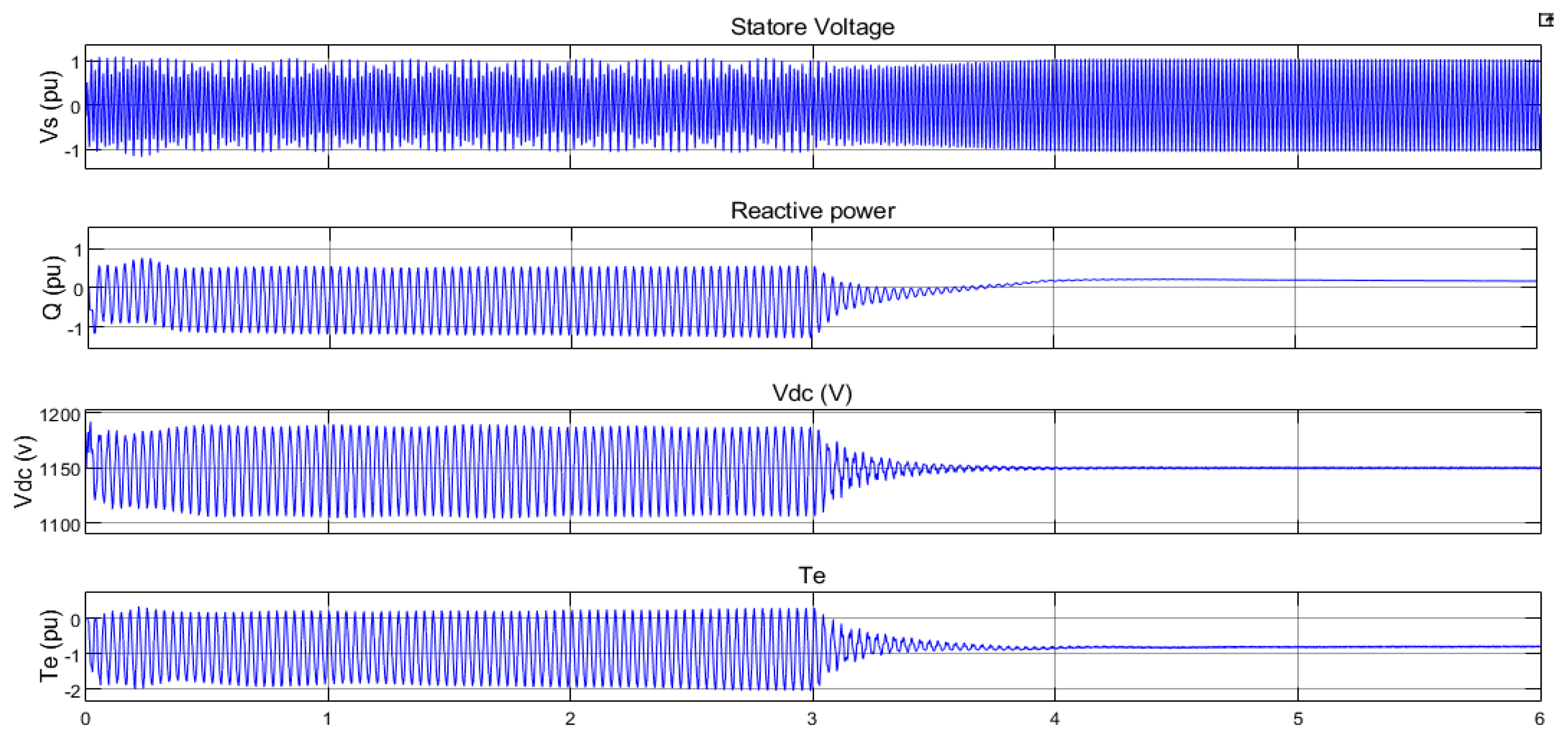
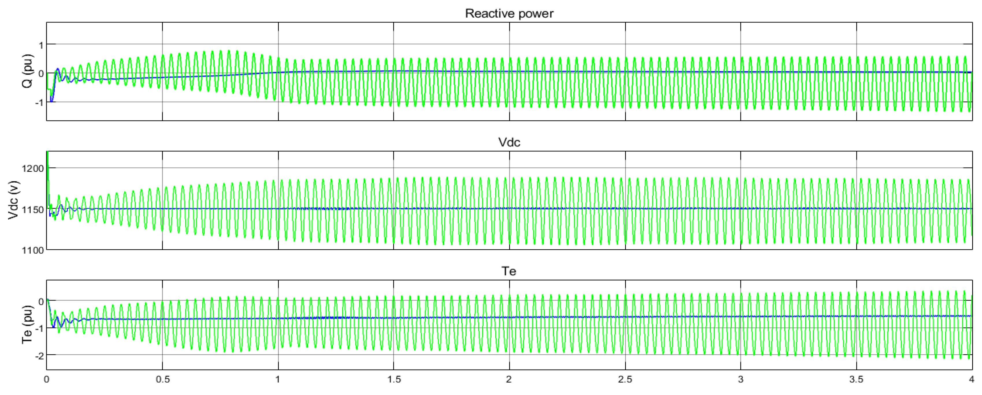
Figure 8 shows the compensation system in the case where the compensation percentage was 25 and the system was stable. In the third second of the simulation, the compensation percentage increased to 75, and the parameters were unstable.
5.1. FLWADC without Time Delay
This part of the simulation showed the application of the fuzzy controller to the studied system in the case where the delays caused by the measured PMU signals were ignored. As shown in
Figure 8, SSR fluctuations were damped by applying a controller to the stator voltage control loop in the GSC. As mentioned, the residue-based analysis method was used to select the input control signal, rotor speed (
), and voltage across the series compensation (
).
The transfer function
G(
s) can be factored as given in (18):
where
is the eigenvalues, and
is the residues of the eigenvalues [
30]. By obtaining the value of
for the sub-synchronous mode corresponding to
of
Table 1, the location of the controller and the capacitor voltage could be selected as the input control signal.
The membership functions of
Figure 7 were quenched by the SSR fluctuations with the 21 fuzzy rules in
Table 3 and receiving the controller inputs, which were the same as the capacitor compensating voltage and its changes from the PMU, as shown in
Figure 5.
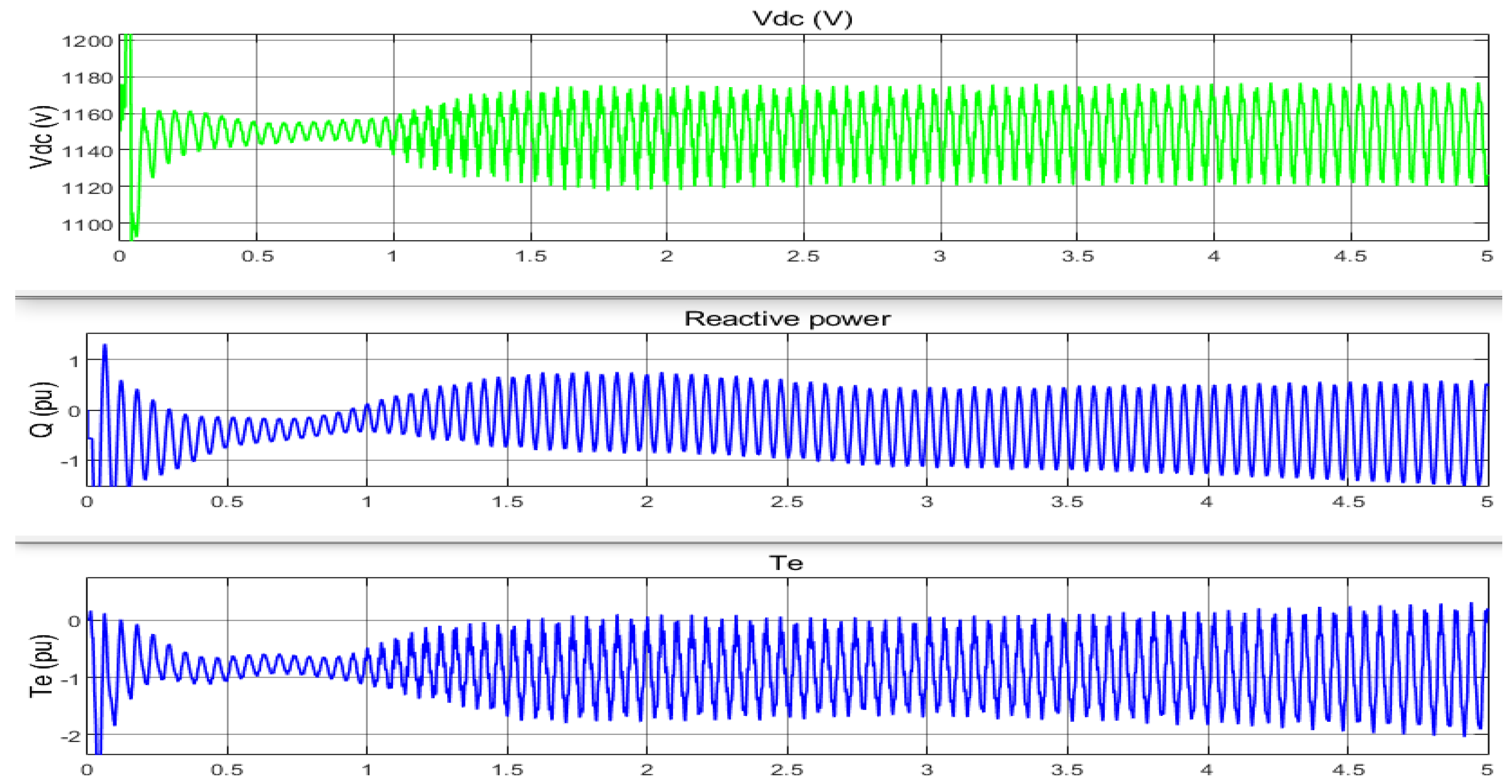
As displayed in
Figure 9, the oscillations were damped in the case where the compensation percentage was 75, and the system was made unstable in the third second of the simulation by applying a fuzzy controller (FLWA).
5.2. Robust FLWADC with Latency Compensation
In the previous section, WAMS-based fuzzy controller simulations were performed in which the latencies due to PMU measurement signals were ignored. In fact, these time delays in sending signals to the controller cannot be ignored since delays are inevitable in telecommunication systems, as shown in
Table 5.
Table 5 shows the communication links and associated delay in a WAMS [
31].
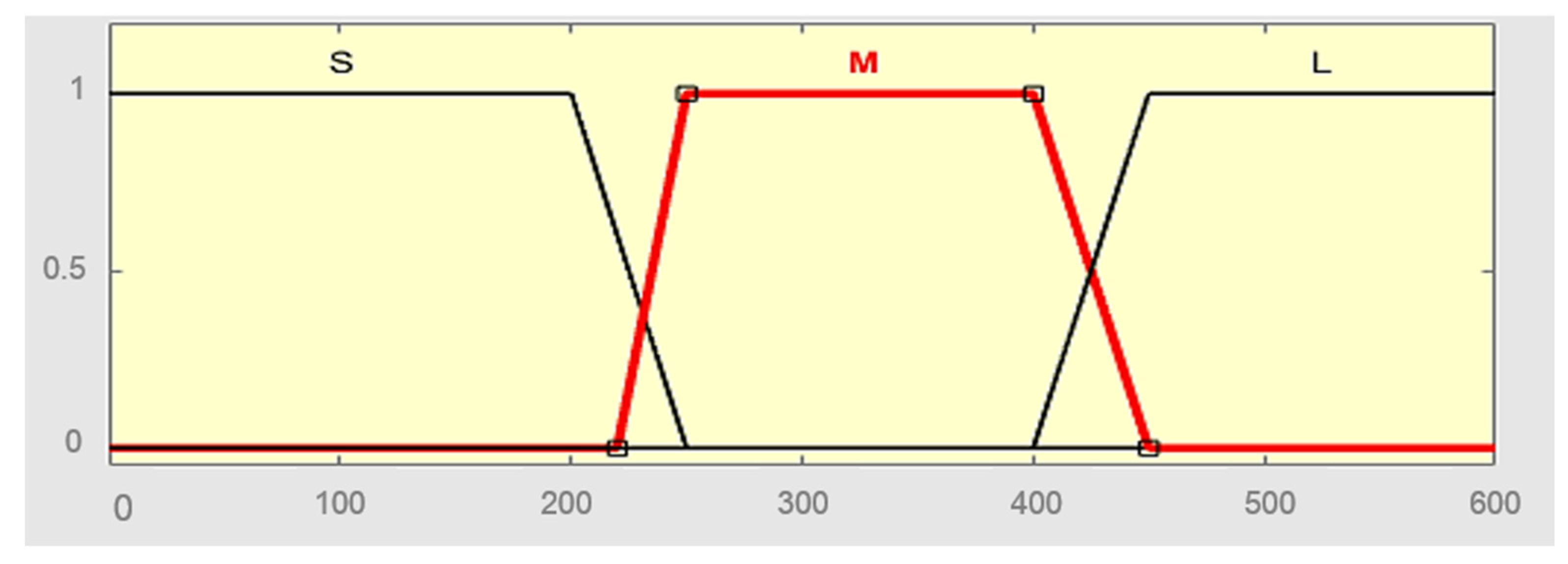
To consider the delays caused by measuring PMU signals, the third input was modeled for another fuzzy input to the fuzzy controller (
Figure 10). As shown, delays were considered in small (S), medium (M), and large (L) membership models. For simplicity, low delays (S) were equivalent to no delays.
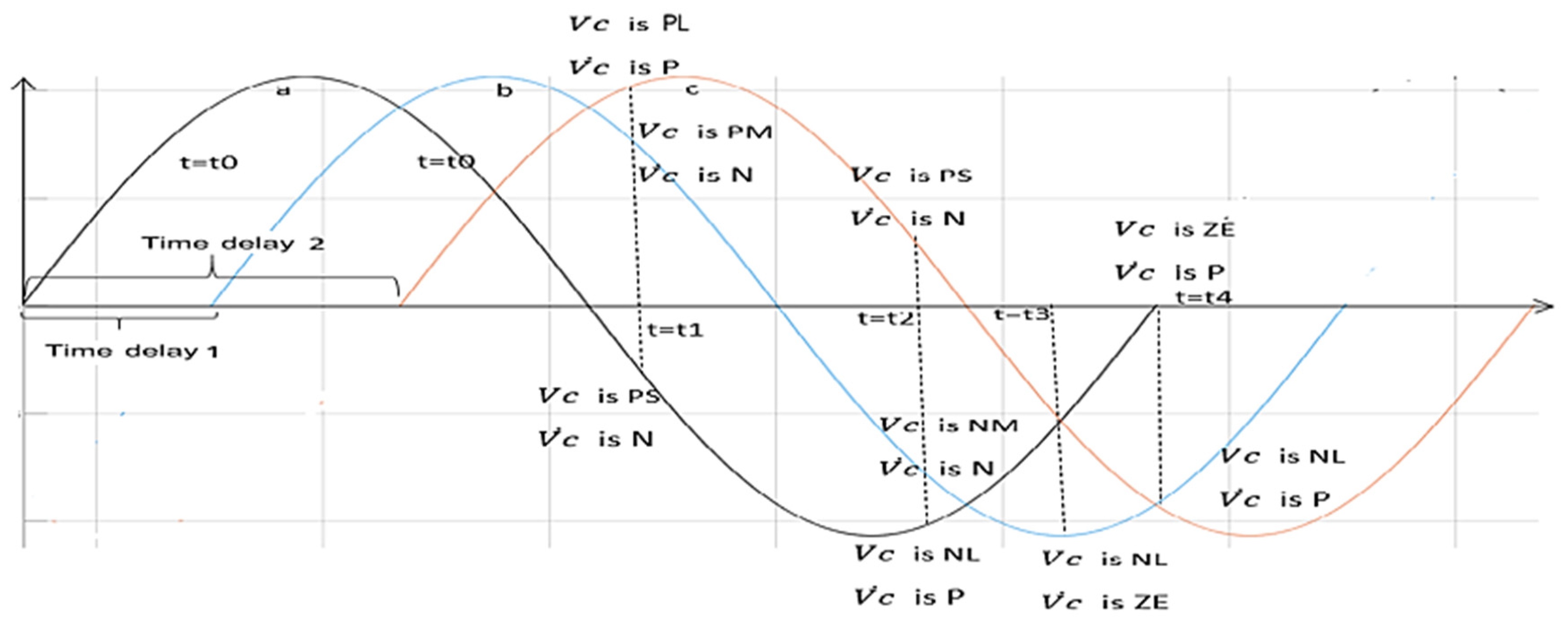
The fuzzy rules of
Table 3 changed for applying this fuzzy input to the fuzzy system, the cause of which is shown in
Figure 11. In addition, the series-compensating capacitor voltage was demonstrated in without-delay (a), medium-delay (b), and long-delay (c) modes.
Consider the moment t = t1 as an example. At this point, the main signal was the no-delay input where
was PS and
was N, which means that the output value of the fuzzy controller equaled ZE. However, if the medium delay was M: time delay 1, the fuzzy rule in this delay,
was PM and
was N, was the output of system the ZE. Further, if the delays were large, L is time delay 2, and the fuzzy rule in this delay was
was PL and
was P, the output of the fuzzy system in this delay was ZE. Similarly, other modified fuzzy rules were shown by considering the delays in
Table 6.
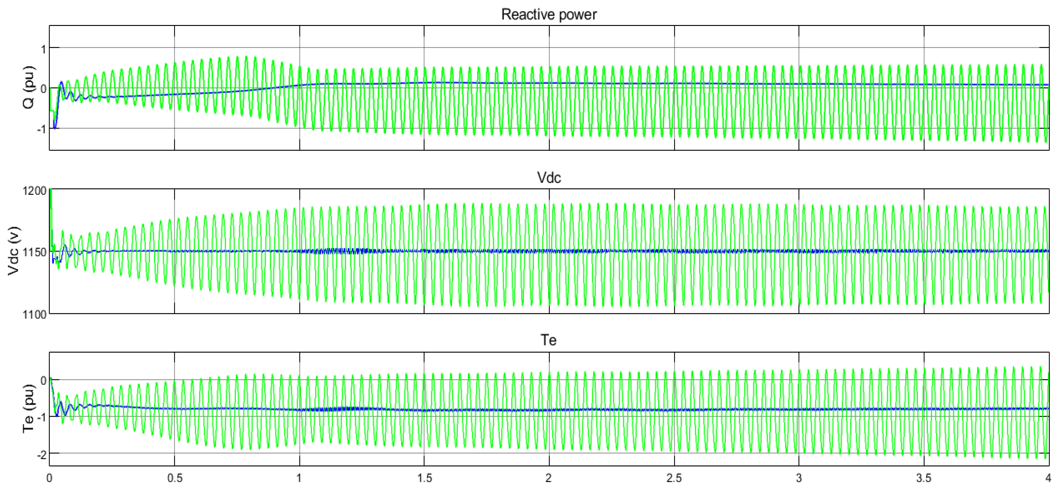
By changing the fuzzy rules, which were modeled by considering the delays caused by PMU measurement signals, the simulation of the studied system with two time delays of 350 and 500
was performed, as shown in
Figure 12 and
Figure 13. As shown, the fuzzy controller damped the fluctuations caused by SSR by considering the changes in fuzzy rules. In this simulation, the compensation percentage was 75 and wind speed was 7 m/s.
Figure 14 shows that the state that the measurement signals applied to the fuzzy controller had a delay of 350
, and the actions of the controller in the first second caused system instability and failed to dampen the system if latency is ignored.


 ,
, 
