Review

Numerical Modeling of Energy Systems Based on Micro Gas Turbine: A Review

1
Institute of Sciences and Technologies for Sustainable Energy and Mobility (STEMS), National Research Council (CNR), 80125 Naples, Italy
2
Italian National Agency for New Technologies (ENEA), Energy and Sustainable Economic Development, 00123 Rome, Italy
*
Author to whom correspondence should be addressed.
Energies 2022, 15(3), 900; https://doi.org/10.3390/en15030900
Submission received: 7 December 2021 / Revised: 21 January 2022 / Accepted: 24 January 2022 / Published: 26 January 2022
(This article belongs to the Special Issue Mathematical Modelling of Energy Systems and Fluid Machinery 2022)

Abstract

:
In the context of the great research pulse on clean energy transition, distributed energy systems have a key role, especially in the case of integration of both renewable and traditional energy sources. The stable interest in small-scale gas turbines can further increase owing to their flexibility in both operation and fuel supply. Since their not-excellent electrical efficiency, research activities on micro gas turbine (MGT) are focused on the performance improvements that are achievable in several ways, like modifying the Brayton cycle, integrating two or more plants, using cleaner fuels. Hence, during the last decades, the growing interest in MGT-based energy systems encouraged the development of many numerical approaches aimed to provide a reliable and effective prediction of the energy systems’ behavior. Indeed, numerical modeling can help to individuate potentialities and issues of each enhanced layout or hybrid energy system, and this review aims to discuss the various layout solutions proposed by researchers, with particular attention to recent publications, highlighting the adopted modeling approaches and methods.

1. Introduction

The reduction of greenhouse gas emissions and the energy transition are fundamental topics within the actual EU recovery plan NextGenerationEU [1]. A transition between the present and a scenario in which energy should be obtained mainly or exclusively by renewable and/or no-carbon sources will spend some decades and one of the researchers’ goals is to reduce this time as minimum as possible. In the meantime, the research is also focused on low-medium term solutions. In this context, distributed energy systems and small-scale smart energy grids represent a viable solution to contribute to greenhouse and pollutant emissions reduction, mainly owing to the benefits of combined heat and power operation [2,3]. Micro gas turbines (MGTs) in the target of 10–100 kW are suitable for distributed generation since their flexibility and versatility in terms of fuel type, variable load, and combined heat and power (CHP) applications [4,5]. During the last two decades of the twentieth century and the first years of the new millennium, industrial and academic research efforts were focused on the development of small-scale energy systems based on micro gas turbines. In more recent times, the research focus was addressed to alternative fuels (i.e., biogas, syngas, methane-hydrogen blends, ammonia), strategies to increase performance levels, and the integration in more complex hybrid energy systems including the presence of renewable sources. The recent frontiers in MGTs research have been encouraged by some attractive features like wide flexibility and versatility, which overcome the limited electrical efficiency. Although the significance of experimental data is universally recognized, numerical modeling is capable to provide a fundamental contribution to the research even in the field of micro gas turbines [6,7]. The variety of modeling approaches is almost boundless, and the researchers set the constraints and the numerical features according to the goal of the investigation and the related accuracy level. In some cases, MGTs are simply modeled as a black box [8], while in other studies mono-dimensional models can be adopted [9]; however, the mainly adopted approach allows to build a zero-dimensional (0D) model of micro gas turbines, starting from the well-known gas turbine theory [10]. In general, a simple thermodynamic analysis appears to be useful in several cases, like steady operation and thermo-economic evaluation, especially if the focus is on the design operating point: these studies usually involve fixed characteristic parameters for each component and the neglecting of some peculiar losses. The introduction of characteristic maps of rotating components and also of the regenerative heat exchanger can lead to more accurate predictions of MGT plant performance. In these cases, a zero-dimensional analysis can be coupled with experimental information of single components, to increase the quality of numerical results and to extend the analysis to off-design conditions with an adequate capability of simulating the actual behavior of the energy system. Research studies are mainly addressed the steady-state behavior since the focus is on single operating points or the time intervals are taken into account allowing to consider part-load operation as a quasi-steady-state one. Nevertheless, in some cases, the introduction of time-based analysis like dynamic or mono-dimensional models is considered for specific purposes.
This review is focused on the recent progress in micro gas turbine numerical modeling, including a detailed investigation on the plant layouts that stand out about optimal energetic performance. The work is organized as follows: the simple and recuperated cycle have been summarized in Section 2, while Section 3 deals with the enhanced layouts (humidified layouts or externally fired MGTs); hybrid energy systems (coupling with Organic Rankine Cycles, Solid Oxide Fuel Cells or solar plants and the integration in smart energy grids) have been reviewed in Section 4. Section 5 provides an outline of the CFD investigation applied to a micro gas turbine, and finally, the conclusions of this work are presented in Section 6.

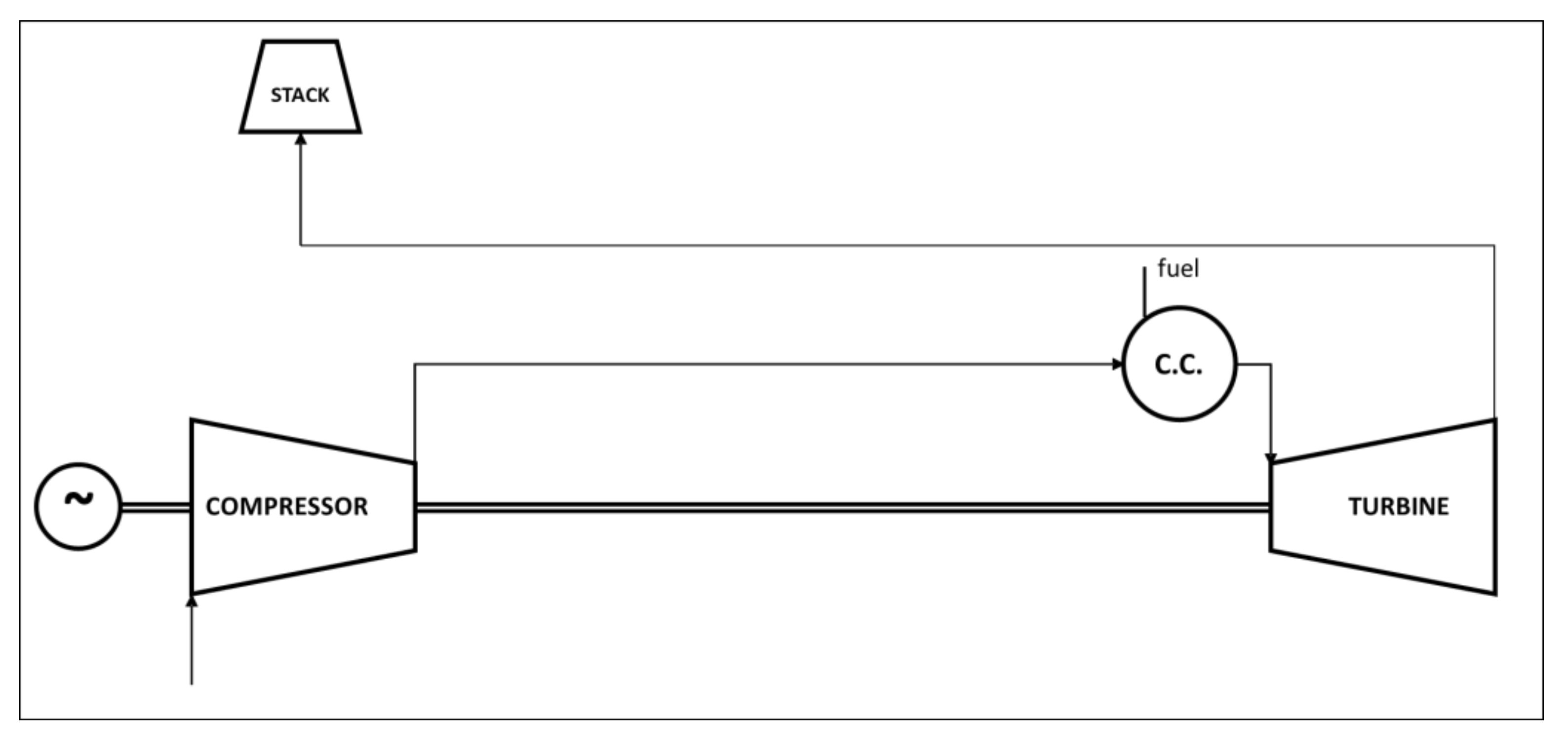
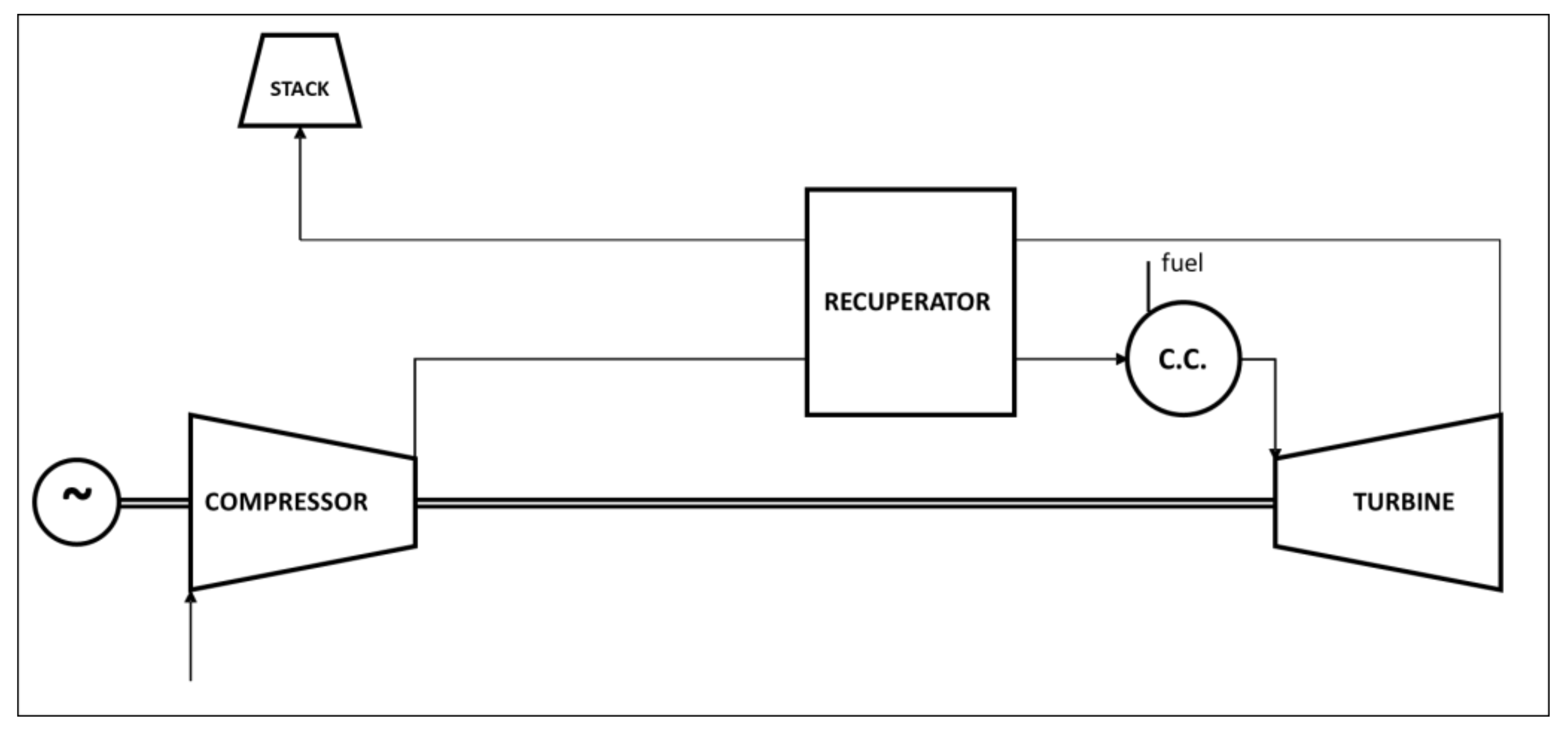
2. Simple and Recuperated Cycles
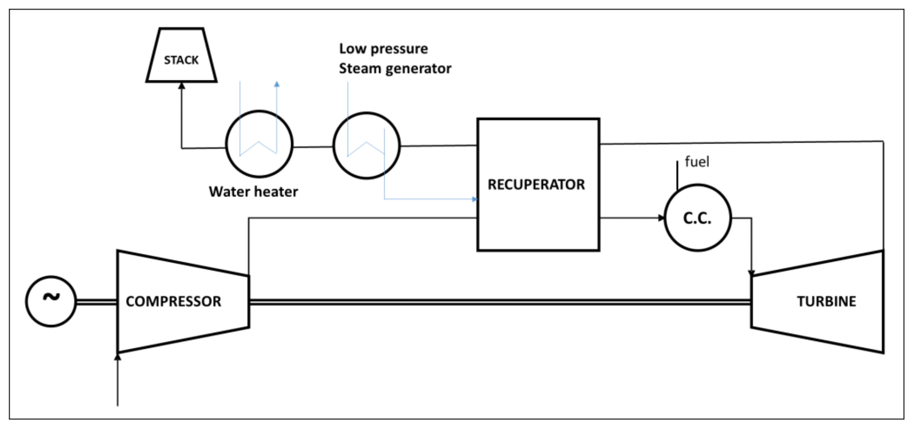
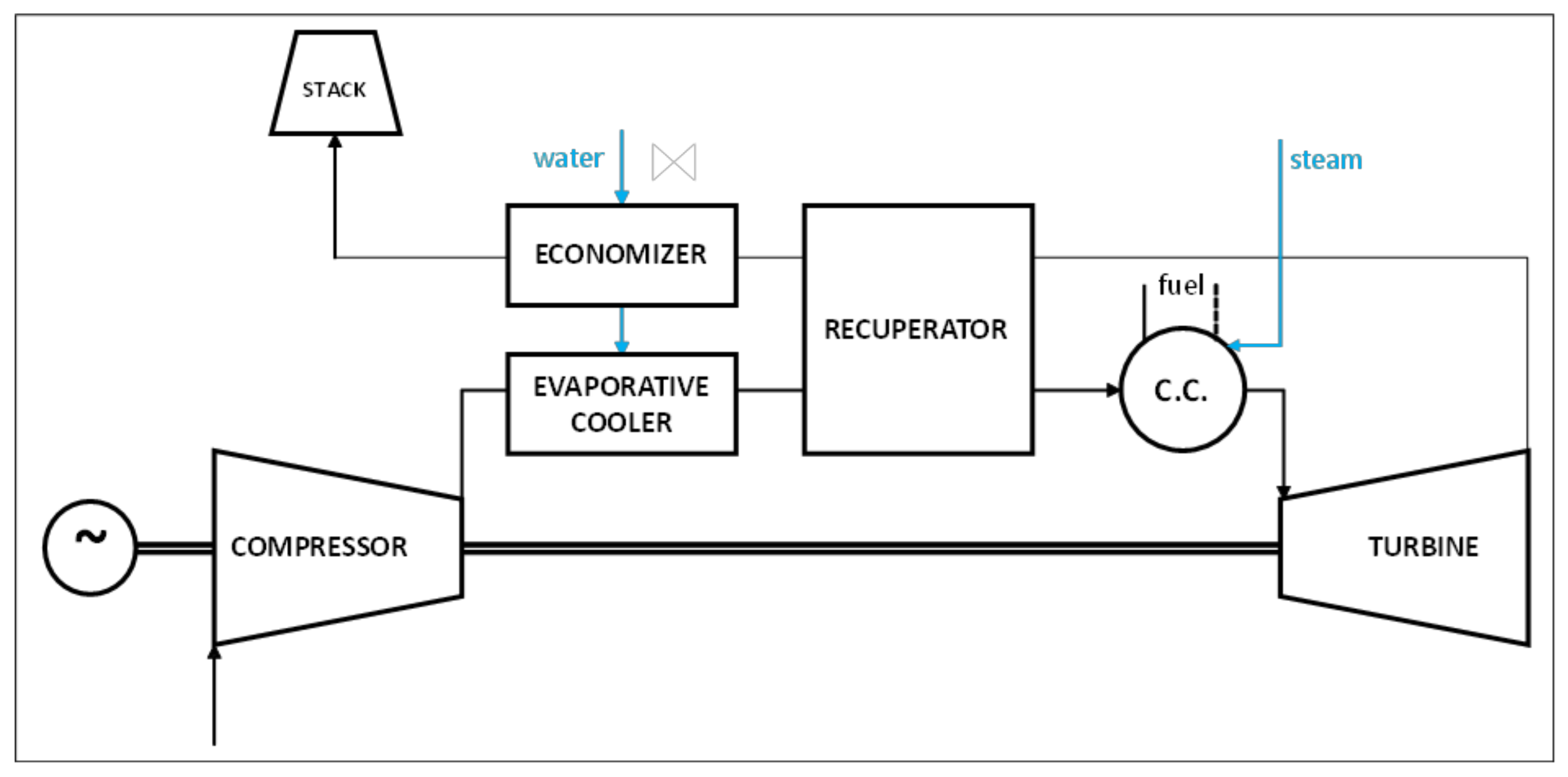
Excluding layout modifications and any system integration, which will be reviewed in the next sections, micro gas turbines follow two schemes: a simple cycle and a regenerative cycle. Figure 1 shows the base MGT scheme in the case of the simple Brayton cycle. The main components are a compressor, a turbine, and a combustion chamber; also, auxiliaries (e.g., fuel compressor and stack fan) and electrical generator should be considered. This scheme ensures the simplest configuration, but the electrical efficiency is not satisfactory, hence it is mainly adopted in the case of micro-turboshaft or aero-derivative MGTs. Hosseinimaab et al. [11] proposed an approach to off-design performance analysis without the introduction of characteristic maps for a simple turboshaft or a double turbo-shaft engine. Altharazi et al. [12] implemented a model of a micro turboshaft, a Kingtech K180, with the commercial software Gasturb and focused their studies on the adoption of liquid biofuels such as palm oil methyl ester (POME) or TPOME in blend with Jet-A.
Adding a recuperator to the base layout allows to realize a regenerative Brayton cycle (Figure 2) and to increase the combustor inlet temperature and the system efficiency, consequently. In this way, it is possible to recover part of the thermal energy available in the exhaust gas that heats the compressed air and increase its temperature. Researchers’ attention is mainly addressed on this configuration, owing to the higher efficiency levels, close to 30% in various commercial MGTs. The approaches are varied and can be better described by thorough literature analysis.
Gopisetty and Treffinger [8] studied a trigeneration system based on a Capstone C65 MGT which is described as a black-box model with the adoption of empirical coefficients, in order to consider part-load operations and the power correction related to the variations of ambient air temperatures; transient operations were neglected since the time response of MGT is higher with respect to other components (heat exchangers). Malinowski and Lewandowska [13] discussed an analytical model for a part-load operation that involves exergy analysis. Model validation was done starting from Capstone C30 experimental data available in the literature. Nipkey et al. [14] adopted a commercial software (IPSEpro), with libraries obtained in their previous papers; the subject of the study was a Turbec T100 modeled by compressor and turbine characteristic maps. Other parameters such as loss coefficients or recuperator effectiveness were obtained through the design case calculations. The authors validated the model in off-design conditions, in the case of adoption of natural gas as fuel, and analyzed the effects on MGT related to the adoption of biogas as fuel. Cáceres et al. [15] defined a biogas-fueled microturbine system in Matlab/Simulink. They proposed to simulate a recuperated MGT with its main controls (speed governor, fuel injection control, and exhaust gases temperature), focusing the analysis mainly on the thermodynamic model of the biogas production process. Caresana et al. [16] analyzed the effect of ambient conditions on MGT performance: the study was performed on a Turbec T100 and, also in this case, compressor and turbine maps were implemented in order to simulate the behavior of the rotating components. The numerical model was validated through a comparison against experimental data. Their analysis highlighted that T100 electrical power decreases with the temperature at a rate of about 1.22 %/°C.
Gimelli and Sannino [17] implemented a multi-variable multi-objective methodology aimed to calibrate and validate a thermodynamic model of energy systems and applied it to Capstone C30 and Turbec T100 plants; the two MGT models have been investigated more in detail in [18] and [19], respectively. The same authors [9] also proposed a one-dimensional model of the Capstone C30 in which rotating components are modeled through the adoption of characteristic operating maps in the GT-SUITE environment. Duan et al. [20] proposed a nonlinear model of a regenerative cycle in which the dynamic response is considered but several parameters were fixed (i.e., isentropic exponents, specific heat capacity, pressure losses) while the volume effect of the pipeline is ignored. The model was established in Matlab and the subject of study was a Capstone C30. Zornek et al. [21] adopted a numerical simulation program developed and validated at DLR [22,23,24] to simulate Turbec T100 behavior in case of low calorific fuels supply. Despite this work being mainly experimental, the authors used a validated model of the MGT plant to investigate the system behavior with and without the embedded control and to optimize the operating range of the turbine. Visser et al. [25] proposed a 0D/1D approach to simulate the performance of turboshaft micro turbines below 30 kW. They started with a 3 kW MTT MGT, modeled with a Gas turbine Simulation Program (GSP), and focused their study on a 1D model of the recuperator [26]. di Gaeta et al. [27] proposed a dynamic model of a controlled commercial MGT (a Turbec T100). A first-order differential equation (ODE) described the dominant dynamics of the MGT imposed by its control system, while the differential equation is coupled to a set of nonlinear maps numerically derived from the matching of a detailed 0D thermodynamic model of the MGT evaluated over a wide range of operating conditions.
In Table 1, a summary of the reviewed literature has been listed.

3. Enhanced Layouts

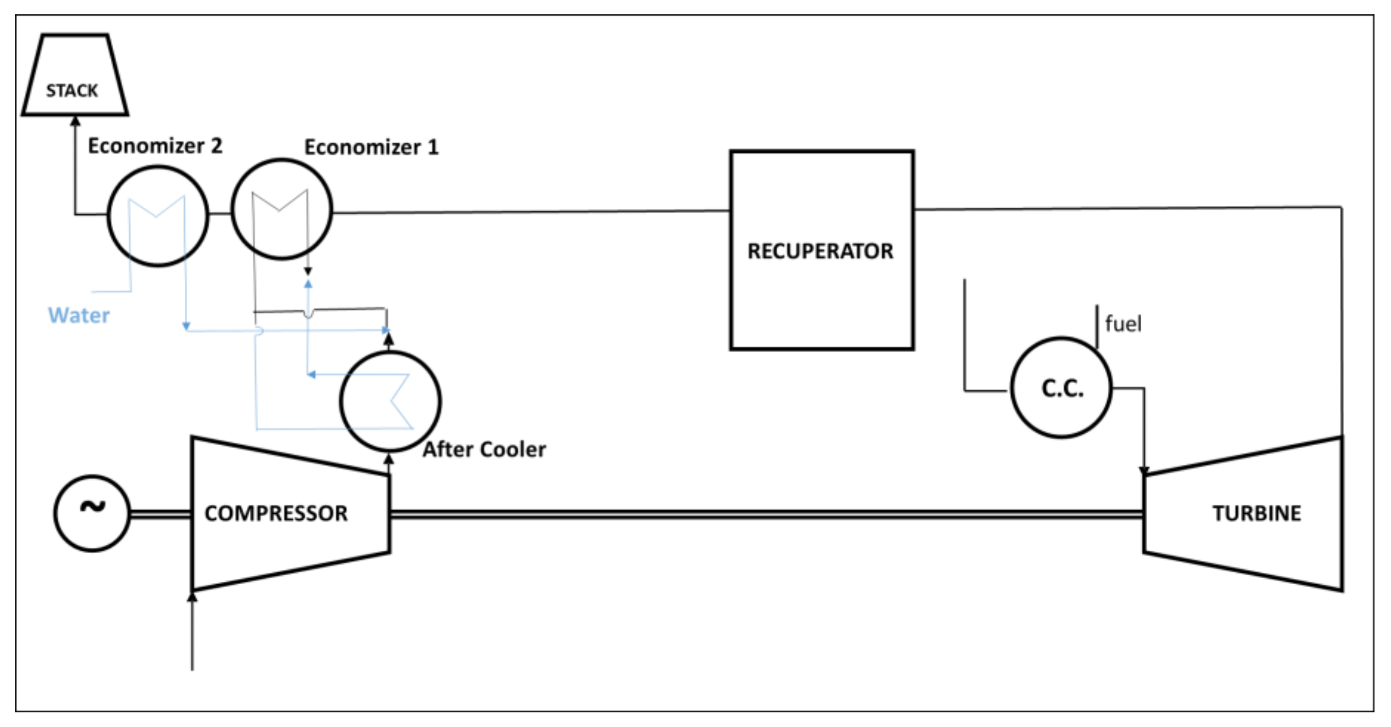
3.1. Humidified Gas Turbines

Steam or water injection in a micro gas turbine plant is standing out in recent years as a solution to improve Brayton cycle efficiency and net power, also mitigating greenhouse and pollutant gas emissions. Water/steam addition leads to a reduction of temperature peaks into the combustion chamber and, consequently, a reduction of nitric oxide (NOx) formation. Research activities are addressed on the determining of several layouts, which can be summarized into three main categories, i.e., the evaporation of the water injected, the injection of steam, and the presence of a humidification tower with a recirculation water loop [28].
Parente et al. [29,30] found that the application of the evaporative cycle to recuperated micro gas turbines could increase both power output and electrical efficiency. They analyzed the effects on two different MGTs (with an electrical power of 100 and 500 kW) and they showed through a thermo-economic analysis that evaporative MGT cycles had lower specific investment costs with respect to traditional MGTs as regard CHP applications. De Paepe et al. [31] studied the influence of steam injection on a Turbec T100 performance. The proposed layout, shown in Figure 3, has been modeled with Aspen Plus and the simulations predicted a rise in electrical efficiency of 2.2% for 5% of steam instead of air.
Montero et al. [32] examined the application of humidified cycle on a Turbec T100 by adding a saturator between the compressor and the recuperator and introducing an economizer just after the recuperator. Results of their simulations highlighted that the mHAT layout (Figure 4) leads to an improvement of the overall efficiency. Ali et al. [33] presented a numerical comparison between three different layouts: an EGR cycle, a STIG, and an mHAT. Results of simulations showed that electrical efficiency increases by 6% for humid and steam cycles and decreases by 9% for the EGR layout, with respect to the base case of a recuperated 100 kW MGT. HAT cycle had the best performance also as regard NOx emissions reduction, despite the combustor should be modified.
Reale and Sannino [34] proposed an H-STIG layout in which both water and steam are injected into the micro gas turbine. Water is injected just after the compressor, while a low amount of steam is injected directly into the fuel feeding system. The comparison between a validated model of Turbec T100 and results of simulations of the modified energy system highlighted the benefit of a small quantity of water (almost 30 g/s with respect to an air mass flow of 800 g/s), namely an improvement of net power and overall efficiency up to 20% and 8.9%, respectively. H-STIG layout (Figure 5) allows also to increase the admissible percentage of H2 blended with methane up to 30%vol, tripling the experimental limit of 10%vol for the dry cycle.
De Paepe et al. [35] compared the impact of different humidified micro gas turbine concepts on the plant performance: micro Humid Air Turbine Plus (mHAT+), Advanced Humid Air Turbine (AHAT), and the REgenerative EVAPoration (REVAP) cycle concept. Results of simulations carried out with Aspen Plus highlighted that the optimal heat recovery can be accomplished using the REVAP cycle concept (Figure 6), with an increase of 4.3% regarding electrical efficiency.
De Paepe et al. [36] also analyzed the potentialities of the M-power cycle concept. This cycle is characterized by a specific saturator module that combines the actions of the aftercooler, evaporator, and recuperator. Numerical simulations allowed us to analyze the performance of the MGT by varying the main parameters of the saturator. Wan et al. [37] proposed an mHAT cycle in which the exhaust is discharged with pressure below ambient (BAHAT). Numerical models were implemented in gPROMS. Results of numerical simulations highlighted that the specific work increases by about 20%, while the electrical efficiency increases by about 2 percentage points with respect to the mHAT cycle.
In Table 2, a summary of the reviewed literature on humidified gas turbine plants has been listed.

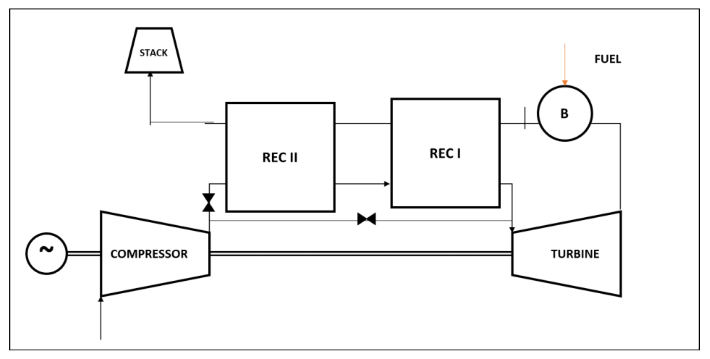
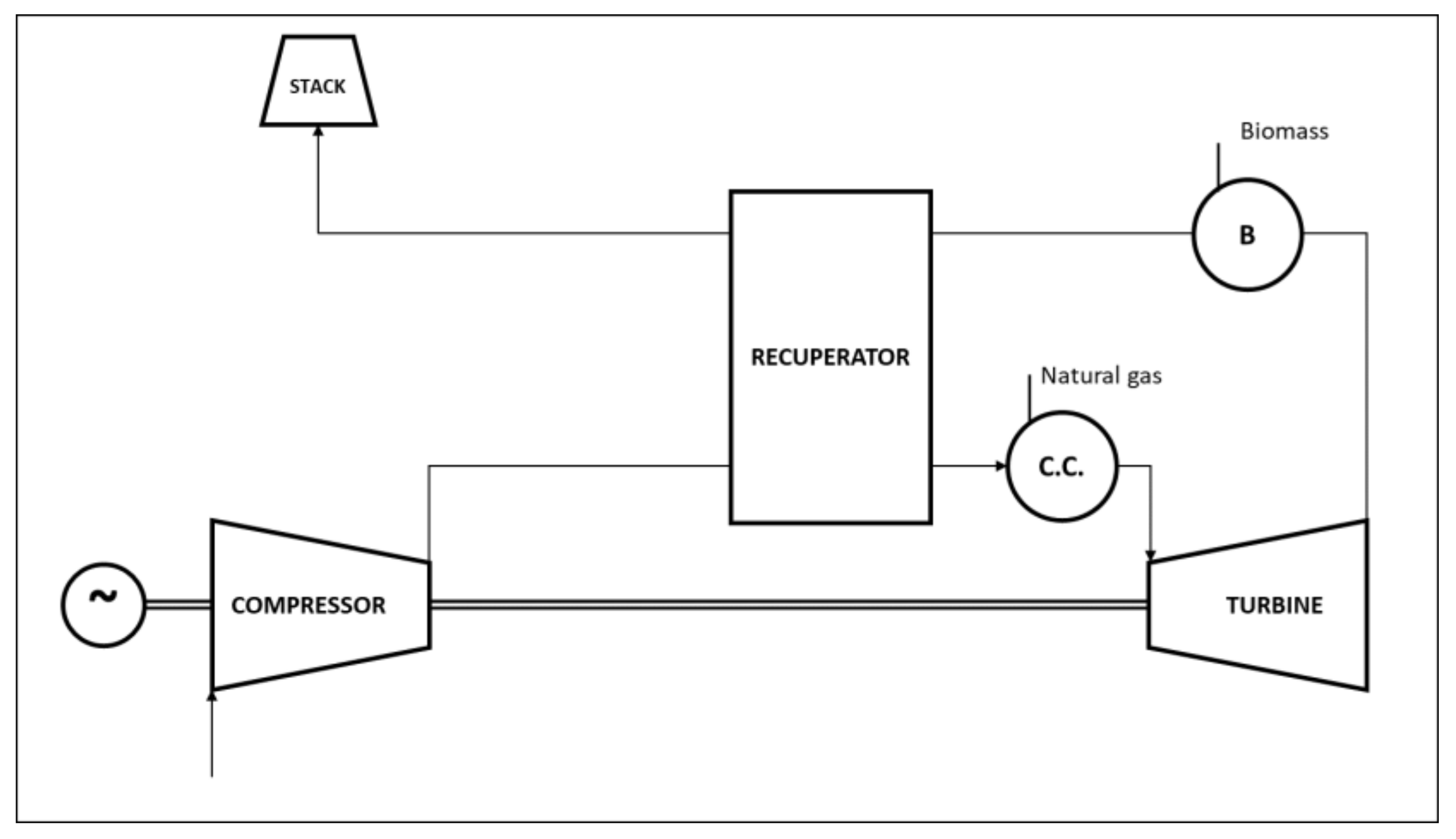
3.2. Externally Fired Micro Gas Turbines

The research on externally fired micro gas turbines (EFMGTs) deals with the combustion of both solid and liquid fuels, like coal and biomass, as well as the heat supplied by renewable sources. As suggested by the layout label, the main feature of an EFMGT is related to the working fluid that not directly participates in the combustion process, but is heated by an external source through a heat exchanger. The adoption of this layout allows the reduction of the requirements in terms of cleaning and composition of fuels and, consequently, of exhaust gases. In other words, in an externally fired micro gas turbine is possible to burn non-standard and critical liquid or gaseous fuels besides solid fuels. While this solution is, of course, mandatory for solid fuels, it can be considered also in the case of liquid or gaseous biofuels, since their use in traditional gas turbines involves several problems, especially without any physical or chemical treatment. EFMGTs “move” this problem to the heat exchanger, since the heat is provided by placing the combustor in the hot exhaust-air stream at the turbine outlet. The externally fired micro gas turbines are usually derived by commercial MGTs, with the main difference in the plant layout represented by a heat exchanger that replaces the internal combustion chamber. The heat exchanger type varies with the type of input thermal power: in the case of fuels derived by coal or biomass, it should operate at high-temperature levels and the layout can present also a combustion chamber; in the case of renewable source, it should operate also for medium-low temperatures, and the burner, if any, is usually located just after the turbine.
As mentioned in [38], one of the early experimental layouts of EFGT dates back to 1992: it was the BM/367/92-Be project, based on a metallic high-temperature heat exchanger (HTHE) with a turbine inlet temperature of 1073 K and HAT with 500 kW. The adoption of EFMGT layouts in case of combustion of solid biomass was analyzed by Traverso et al. [39], proposing a layout in which a heat exchanger and an external combustion chamber replace the internal combustor of a regenerative micro gas turbine (Figure 7); this scheme also involves an air bypass on the recuperator cold side. The EFMGT was modeled by TRANSEO software, once validated with experimental data, both for steady and unsteady behavior [40,41,42].
Pantaleo et al. [43] proposed a comparison between an IFMGT and an EFMGT. Thermodynamic analysis was carried out through the adoption of the software Gate-cycle, investigating several blends of natural gas and biomass. The authors focused their attention mainly on a thermo-economic comparison. As expected, a trade-off between efficiency and profitability has been noticed along with the significance of a dual fuel MGT for the integration of renewable and fossil fuels. Riccio and Chiaramonti [44] proposed a dual fuel layout, in which both internal combustor and external furnace coexist in the same layout (Figure 8). Fresh air is first heated by the exhausts coming from a furnace, in which biomass is burned, and then comes into a combustion chamber fueled by natural gas. This solution can lead to the flexible use of solid and gaseous fuels. The study was based on a steady-state thermodynamic matching analysis of a Turbec T100 carried out by AMOS, an in-house software.
Datta et al. [45] performed a parametric thermodynamic analysis of 100 kW EFMGT, in order to identify the ideal operating conditions for an EFGT decentralized plant by analyzing the energetic and exergetic performance variations with thermodynamic operating parameters. Once the optimal pressure ratio of the turbine has been fixed, the most desirable boundary conditions arise from a trade-off between higher thermal and exergetic efficiency versus smaller heat exchanger size.
In Table 3, a summary of the reviewed papers dealing with externally fired MGT has been listed.

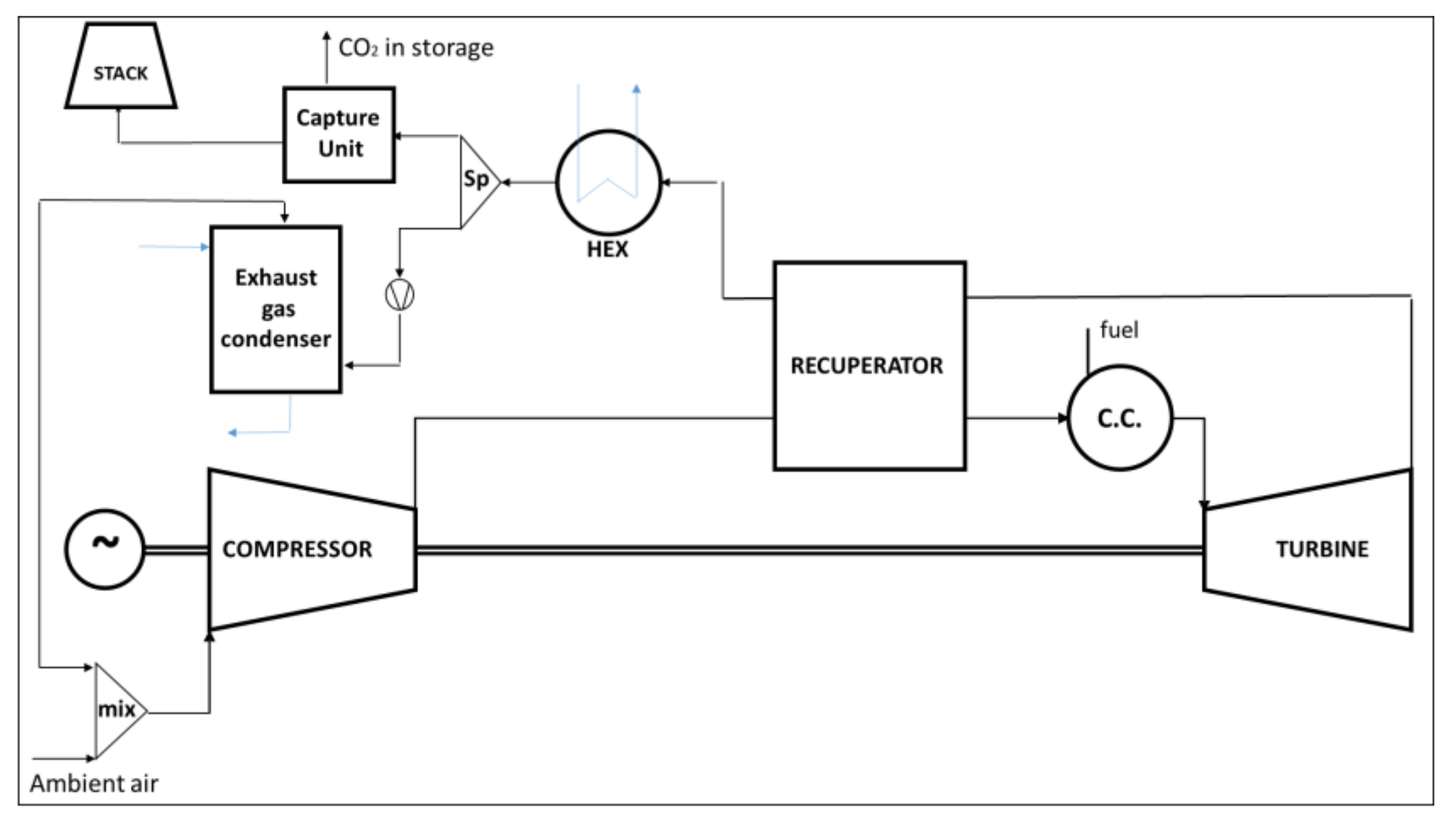
3.3. Further Layouts

Several researchers have proposed original and noteworthy plant schemes that are hard to categorize in a single group, due to the uncommon conceptualization of the components’ layout.
Cameretti et al. [46] proposed a recuperated MGT layout with both recuperator bypass and partial exhaust gas recirculation (EGR) aimed to find out operating conditions that satisfactorily meet NOx reduction and cycle efficiency. Numerical simulations have been carried out by an in-house code, while CFD analysis was done using a Fluent solver. Majoumerd et al. [47] extended the adoption of a Turbec T100 thermodynamic model already validated in [14] to a more complex system with a CO2 capture unit; the authors compared an EGR (Figure 9) and a HAT cycle with a focus on improved carbon capture efficiency. The base MGT plant showed a higher cost for CO2 capture compared to EGR and HAT layouts and the authors suppose that this feature will support the deployment of carbon capture in distributed power generation; the detailed analysis of EGR and HAT cycle modeling with IPSEpro software has been disclosed in [48]. Ali et al. [49] modeled in Aspen HYSYS a micro gas turbine with CO2 injection and EGR, coupled with an amine-based CO2 capture plant; base MGT, CO2 injection, and pilot-scale carbon capture plant models were validated against experimental data. Hampel et al. [50] investigated a promising plant layout made by pure hydrogen-fueled T100 MGT coupled with a dehydrogenation unit that processes liquid organic hydrogen carriers (LOHC). The advantage of such an energy system is that the hydrogen needed to feed the MGT is obtained by the dehydrogenation endothermal process which is supplied by the gas turbine exhaust gas; the numerical analysis showed the thermodynamic feasibility for three of the four investigated cases.

4. Hybrid Energy Systems Based on MGT

The assumption of a hybrid energy system is the multiplicity of energy conversion that can be achieved by the integration of two or more devices or by the combination of two or more fuels for the same device, as exhaustively described by Manwell [51]. The hybrid energy systems are usually made by a renewable energy plant coupled with thermal prime movers like internal combustion engines or gas turbines; alternative hybrid layouts involve the waste heat recovery approach, in which two or more energy conversion systems are coupled based on the temperature level of the heat source, like a gas turbine and organic Rankine cycle (ORC) and solid oxide fuel cell (SOFC) with a gas turbine, that will be discussed in the following subsections. According to this summary of hybrid energy systems, it is clear the convenience of MGT, whose use is favorable due to the flexibility in the operating domain and to the high-quality recoverable heat at the turbine exhaust. The main advantage of numerical modeling applied to novel hybrid plant configuration is the capability to individuate potentialities and issues of each layout, although the need for experimental data in order to validate the models. The hybridization can be obtained by substituting MGT components with more convenient elements or by introducing new components, such as heat exchangers, which can turn into a thermal connection with other energy systems. The hybrid energy systems based on micro gas turbines reviewed in this work are four: a first one in which the Brayton cycle is the topping one, a second in which the MGT is the bottoming one, a third in which MGTs are connected with solar power plants and a fourth in which the MGT is a node of a small-scaled smart energy grid. In the latter case, the hybridization is achieved by the integration of different energy conversion plants in a single smart grid, whose control system manages the matching between supply and demand.

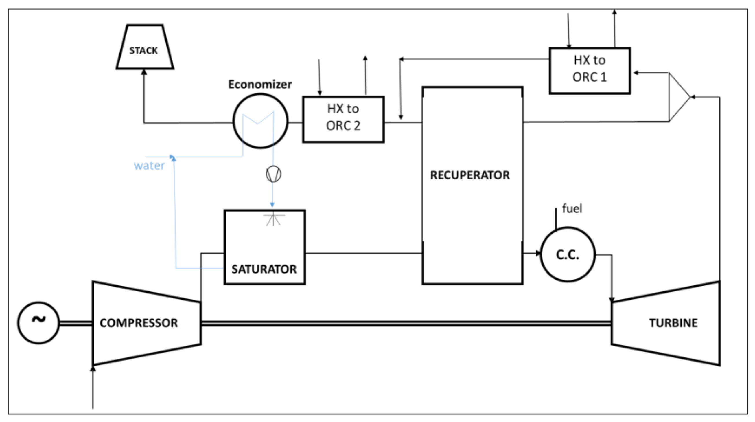
4.1. MGT—ORC Systems

Organic Rankine Cycle (ORC) represents a technology of great interest as waste heat recovery (WHR) system in the medium and low-grade energy recovery, also in the typical range of MGT exhaust gases temperature [52,53]. The ORCs are closed-cycle plants whose simple layout includes a pump, a heat exchanger for the organic fluid temperature increase, an expander that generates electrical power, and a condenser; the hybridization is performed by the MGT exhaust gas which flows into the ORC heat exchanger with the aim of evaporating the compressed organic fluid. The thermal recovery performed by ORC allows to increase the combined cycle efficiency up to 15% more than base MGT [54]: by this way, MGTs can become advantageous for small-scale power plants, thanks to the environmental and fuel diversification [55].
Chacartegui et al. [56] presented an integrated energy system based on an mHAT cycle and two bottomed ORC plants. The topping cycle is combined with a medium-temperature ORC and a low-temperature ORC. The proposed scheme is shown in Figure 10 and its global efficiency is above 50%. The thermal heat which is available at the exhausts of the recuperated mHAT is used both as thermal input of the ORCs and to preheat the liquid water needed on the saturator.
Moradi et al. [57] investigated a micro-CHP system consisting of a fluidized-bed gasifier, a 100 kW steam injected micro gas turbine, and a bottomed ORC cycle, along with a heat recovery steam generator (HRSG) that produces steam both for the gasification process and the STIG. Numerical simulations have been performed with Aspen Plus and included syngas purification systems, an improved gasifier model, and the operating limits of MGT. Despite the results of syngas fueled cycle with steam injection showing an increased electrical power but a slight reduction of electrical efficiency, the integration of different energy systems has been proved to be capable of providing energy and environmental benefits. Nazari et al. [58] defined an integrated energy system composed of an EFMGT, a transcritical ORC, and a Li-Br/H2O absorption refrigeration cycle (EFGT-ORC-ARC). In this way, the two renewable sources (solar and biomass) allow the combined production of electricity, hot water, and cooling load. A steady-state numerical study was carried out with several constraints (i.e., ideal gas mixture, compressor, turbines, and pumps with constant isentropic efficiencies) in order to obtain an exergo-economic assessment through a thermodynamic code developed using Equation Engineering Solver (EES) software. Compared to the base case, the optimized integrated plant can achieve up to 17% higher electrical power, up to 23% higher cooling power, and about 200% higher heating power, with a first law efficiency of 54%. Nazari and Porkhial [59] proposed a multi-generation system composed of a solar field, a biomass-fueled externally fired gas turbine, a steam Rankine Cycle, an ORC, an absorption chiller, and a desalination plant. The whole system has been modeled by EES software and the results showed the good potential of potable water production, a higher cooling capacity compared to the available literature, along with an achievable exergy efficiency of 21.5%. Xiao et al. [60] presented a novel configuration combining a solar (a heliostat field) micro gas turbine with steam injection and a bottomed ORC. A numerical model was developed and validated by experimental or referenced data and results of simulations in representative days (i.e., spring equinox, summer solstice, autumn equinox, and winter solstice) highlighted that the proposed system increases the system flexibility in dealing with complex loading conditions and the solar energy has a significant impact on fuel saving. Cameretti et al. [61] proposed the integration of an MGT with an ORC system and a solar field, whose aim is to increase the MGT recuperator inlet temperature. The authors carried out both thermodynamic numerical simulations of the entire system and CFD analysis of the MGT combustor in the case of natural gas and biogas as fuel. Such plant layout maximizes the heat from solar source with a reasonable collectors’ surface achieving satisfactory performance in CHP mode as well as at part-load operation. Baccioli et al. [62] investigated the improvement of the anaerobic digestion plant installed in Viareggio (Italy) by adding to the biogas fueled 600 kW MGT an ORC system. Transient and steady-state simulations have been performed in the AmeSIM environment and the authors considered three different ORC sizes (30–40-50 kW) and individuated that the most valuable solution from a thermo-economic point of view is the 40 kW case. Reale et al. [63] studied an integrated gasifier-MGT-ORC energy system; the convenience of including a syngas fuel from gasification of organic municipal waste has been also examined. Thermodynamic simulations have been carried out with Thermoflex, while the issues related to the combustion process of biogas-syngas blends are analyzed by CFD simulations in Ansys CFX.
Table 4 lists the summary of the reviewed literature about the MGT-ORC plant.

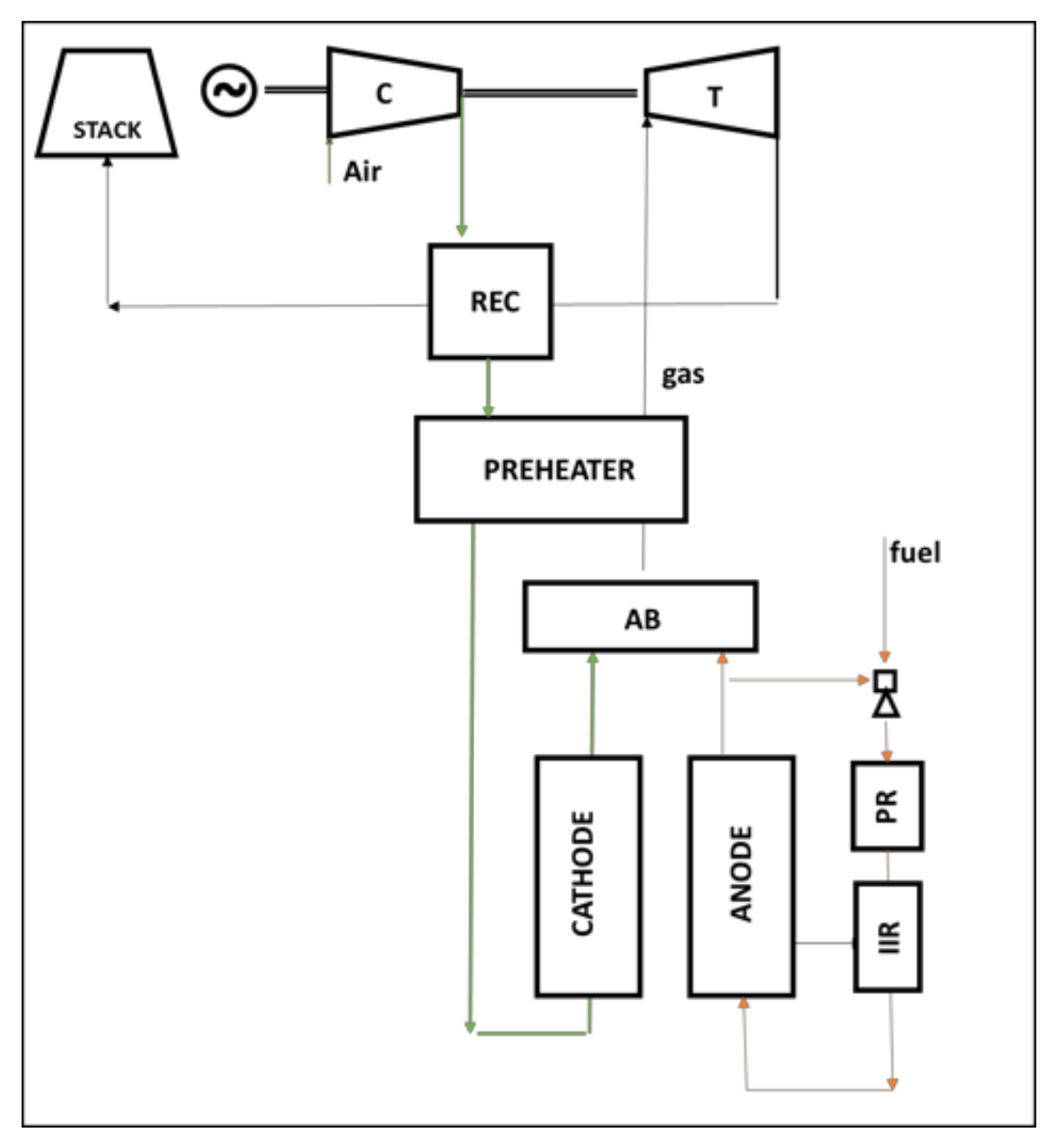
4.2. SOFC—MGT Systems
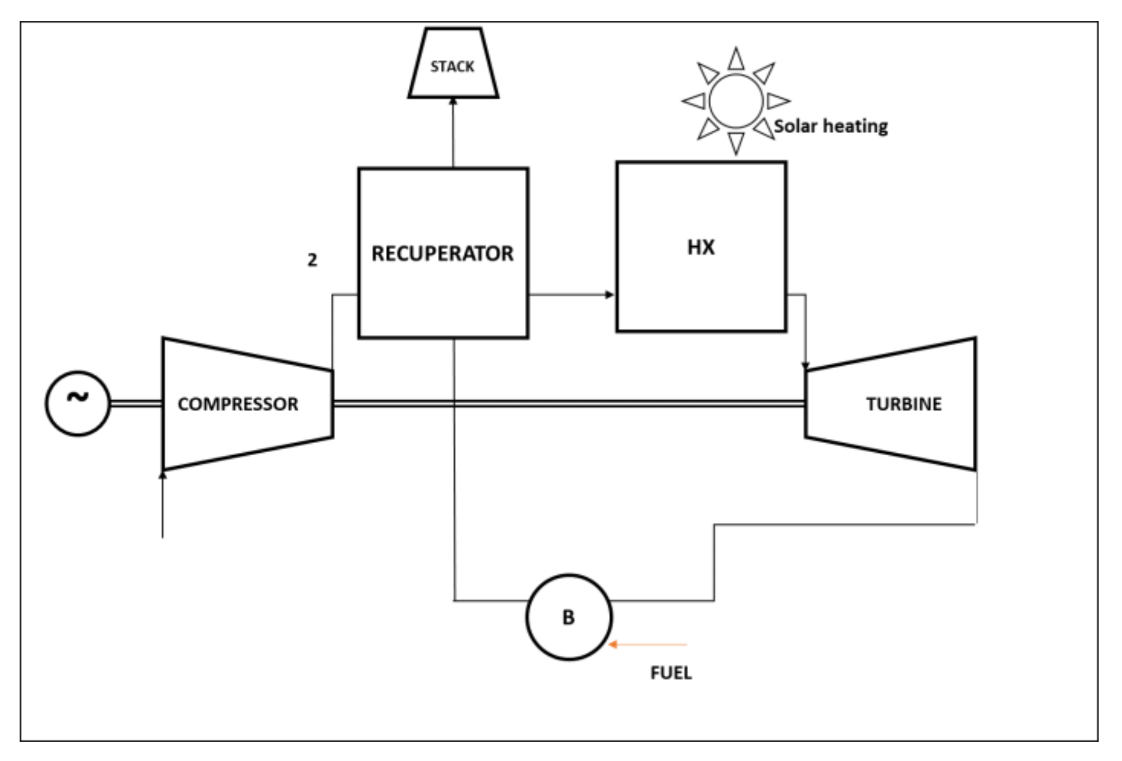
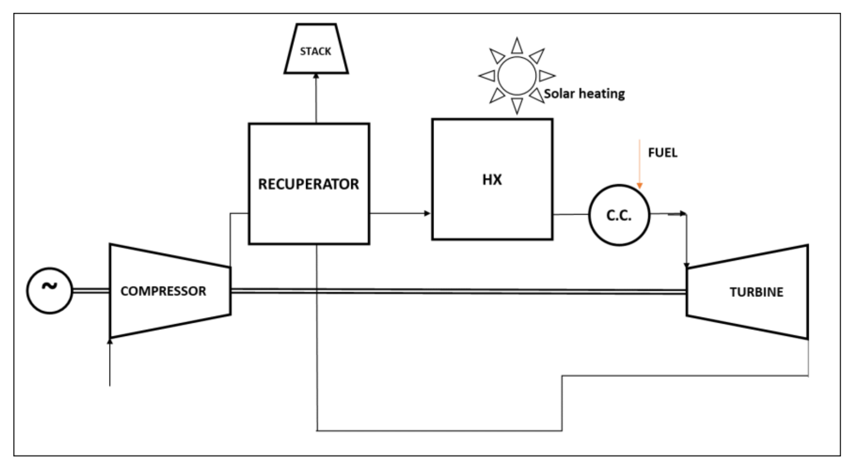
Solid Oxide Fuel Cells (SOFCs) convert the chemical energy of a fuel into electrical energy through high-efficiency electrochemical processes; the typical operating temperature of a SOFC makes convenient the coupling with MGTs. In particular, the heat rejected from the fuel cell is transferred to the compressed air with the purpose of substituting the MGT combustion chamber.
Costamagna et al. [64] analyzed the design and off-design behavior of a hybrid system based on a recuperated MGT and a high-temperature SOFC reactor, considering also the MGT variable speed control system. Results of simulations showed a potential of achieving an efficiency of more than 60% at the design point and greater than 50% at part load, considering a SOFC reactor of about 250 kW and a 50 kW MGT. Ferrari et al. [65] implemented the model of a hybrid MGT-SOFC system using the in-house TRANSEO tool developed in MATLAB/Simulink environment, which includes an ejector model based on 1D-CFD equations able to predict the dynamic behavior of the component. The off-design analysis of the hybrid system showed that FC temperatures too high or too low should be avoided because they could drive the compressor operation too close to the surge line or the MGT overspeed. Kaneko et al. [66] proposed the dynamic model of a 35 kW hybrid system based on a biomass-fueled SOFC coupled with an MGT; the main features of the model are two controllers of power and SOFC temperature that provide an actual estimation of the time response for each component under different boundary conditions. Bang-Møller et al. [67,68] studied a hybrid CHP plant combining a two-stage gasifier, a SOFC stack, and an MGT: numerical simulations allowed to compare three different combinations (gasifier-SOFC, gasifier-MGT, and gasifier-SOFC-MGT) and to individuate that the gasifier-SOFT-MGT layout presents the best energetic- and exergetic-based electrical efficiency. Bakalis and Stamatis [69] studied the integration of a Siemens-Westinghouse SOFC with four commercially available recuperated MGT plants (Capstone C30 and C60, Parallon 75 kW, and Turbec T100); the model has been carried out with Aspen Plus and considers the off-design behavior of rotating components through user-defined Fortran subroutines. The referring layout is shown in Figure 11: the SOFC model consists of a pre-reformer (PR), an indirect internal reformer (IIR), an afterburner (AB), a preheater, and, obviously, a cathode-anode stack. The results showed the increasing trend of system efficiency with the decrease of MGT power for a fixed SOFC generator.
Fryda et al. [70] investigated three different small-scale CHP configurations: gasification at 4 bar pressure and MGT, gasification at 1.4 bar pressure and SOFC, gasification at 4 bar pressure, and SOFC-MGT. Numerical simulations were carried out using Aspen Plus, and the results highlighted that SOFC-MGT was more efficient with respect to both simple MGT and SOFC. Zhao et al. [71] proposed a hybrid SOFC-HAT-CCHP (combined cooling, heating, and power) system based on methanol-reforming. The model is based on Aspen Plus and the main outcome shows that the introduction of humid air turbines increased the power generation reducing at the same time the coal consumption rate. A SOFC-MGT-ORC hybrid plant for power generation is proposed by Ebrahimi et al. [72]: the authors highlighted through a parametric analysis that this combination can be useful to convert as much as possible fuel to power, since MGT can use high-quality SOFC stack gases and ORC uses medium quality MGT exhaust gases. Results of numerical simulations showed that the electrical efficiency of the energy system can reach about 61%. Wongchanapai et al. [73] performed a sensitivity analysis on a direct internal reforming biogas SOFC-MGT hybrid CHP plant, focusing on energy and exergy balances. The four parameters considered were air-steam mixtures as reforming agents, fuel utilization factor, turbine inlet temperature, and compression ratio, and the several sets of information resulting from the analysis represent valuable knowledge for direct-biogas SOFC operational performance. Krummrein et al. [74] investigated the performance related to the use of biogas fuel for their hybrid power plant SOFC-MGT demonstrator. Results of steady state simulations showed that the thermodynamic parameters are only slightly influenced by the substitution of methane with biogas. Di Carlo et al. [75] presented a SOFC-MGT system integrated with a biomass gasifier whose model has been validated against experimental data. Results highlighted that wood-gas rich in H2 and CO can be used in SOFCs and that the total efficiency of the entire system is between 36% and 44%, also considering the presence of the gasifier. Perna et al. [76] investigated the performance of a SOFC-MGT with a biomass downdraft gasifier (BG). The comprehensive system model has been validated against experimental data, and the numerical simulations were carried out considering electrical, thermal, and combined heat and power production: such integrated energy conversion system significantly improves the electric efficiency and accordingly enhances the exploitation of biomass as a primary energy source. Isfahani et al. [77] proposed a hybrid system based on SOFC and MGT with capturing CO2 and a three-reactors chemical looping for hydrogen generation from natural gas; their model allows the MGT combustor to burn the non-reacted hydrogen. A sensitivity analysis has been performed by varying several SOFC parameters, and the direct correlation between plant efficiency and operating pressures has been demonstrated. Zhen et al. [78] proposed an integrated distributed energy system consisting of SOFC and MGT with solar thermochemical hydrogen production. The system can be divided into three parts: the power plant (SOFC-MGT), the solar thermal methanol decomposition aimed at hydrogen-enriched fuel production, and a waste heat recovery system. Exhaust gases from MGT heat first the compressed air and hydrogen-rich syngas and afterward pass through the Li-Br absorption chiller. The DES numerical model is validated by comparing the results with published literature. Karimi et al. [79] proposed a SOFC-MGT-ORC energy system combined with a rice straw biomass gasifier. The authors carried out a parametric analysis aimed to individuate through a multi-objective optimization the best compromise between exergy efficiency and cost rate. Pantaleo et al. [80] analyzed a particular case of study of a major Italian coffee roasting and processing plant, with an operating cycle of 6 h per day. They proposed and numerically compared three different solutions: an intermittent waste heat recovery via thermal energy storage (TES) and ORC, a recuperated MGT coupled to the existing modulating gas burner, and a non-regenerative topping MGT with the direct recovery of the turbine outlet air for the roasting process. The authors concluded that the investigated solutions are not economically profitable for an operating cycle of 6 h/day.
In Table 5, a summary of the literature reviewed in this subsection has been listed.

4.3. Solar—MGT

Kautz and Hansen [81] proposed an EFMGT based on a Turbec T100 in which the recuperator became the heat exchanger linked to the external burner. In their work, a further heat exchanger could be added in order to consider an additional rate of input thermal power by solar panels (Figure 12); the numerical computation has been carried out with Aspen Plus software. Despite an externally fired gas turbine allowing the burning of “dirty” fuels along with the decrease of fuel consumption, using the solar source as the main heat gain and the biomass as backup fuel can lead to a fully renewable energy system.
Aichmayer et al. [82] compared two different configurations of a solar receiver integrated into a small-scale dish-mounted hybrid solar micro gas-turbine system. In the first layout, the solar receiver is pressurized and located just before the turbine. The second configuration is an atmospheric one, in which the receiver is after the turbine. Steady-state thermodynamic models were realized in Matlab, using also the REFPROP database, while the receiver design was carried out by a validated coupled CFD-FEM analysis. The pressurized receiver stood out as the only suitable component for a micro gas turbine-based solar dish system, due to the assumed pressure drop constraint. Yang et al. [83] proposed a thermodynamic model and a real-time control strategy of a solar MGT coupled with a thermochemical energy storage (TCES); the mathematical model involved the actual direct normal irradiance (DNI) and the disturbance for both short and long periods. The simulations showed a low risk of surging or choking and highlighted the better performance of constant turbine outlet temperature operation control compared to constant shaft speed control. Cameretti et al. [84] studied a hybrid plant consisting of a micro gas turbine with a solar field with a tower-placed receiver (Figure 13). Simulations on the proposed layout with solar heating and internal combustion chamber were carried out on both the integrated energy system (with Thermoflex software) and the combustor (CFD analysis).
Wang et al. [85] also proposed a solar receiver MGT scheme in which the receiver is located between the recuperator and the combustor. Giostri et al. [86] described a solarized micro-gas turbine model coded in Matlab. In particular, a raytracing model allows to estimate the optical performance of the solar tower system, while the recuperated MGT was modeled starting from previously validated models of the same authors [87]; the thermo-economic indexes have been also analyzed. Solar-MGT, without any storage system, appears currently not competitive if compared with PVs, as regards the levelized cost of electricity (LCOE) and the authors proposed hybridization with gas turbine compatible fuels as a solution to both increase performance levels and reduce LCOE. Aichmayer et al. [88] proposed a thermo-economic analysis of a solar dish MGT combined cycle power plant consisting of an array of hybrid solar dish micro gas turbines and a single large steam cycle. Each MGT size is 80 kW while the combined power plant nominal power is 150 MW. The performance of this power plant is analyzed through an in-house thermo-economic tool, DYESOPT. Results of simulations highlighted that the proposed optimal design presents a cost 46.1% higher than a contemporary molten-salt tower CSP plant and that at this moment it is an unattractive investment. In the case of solar-MGT plants, numerical simulation is also useful to investigate components that establish the link between MGT and the solar plant. For example, Giovannelli et al. [89] studied the effect of cavity geometry on solar receiver effectiveness. They designed a high-temperature cavity solar receiver for a 5 kW Dish-MGT system and analyzed it through a CFD analysis. The adopted software is Ansys Fluent, and the results of the configurations comparison highlighted their differences and contributed to individuate the better one.
In Table 6, a summary of the reviewed literature has been listed.

4.4. MGTs in Distributed Energy Networks and Smart Energy Grids

MGTs represent a valuable solution as nodes of smart energy grids in which both renewable and traditional sources are considered. With respect to the layouts discussed in previous sections, the key feature of these hybrid energy plants is the energy management system: most of the research activity on this topic is focused on modeling and simulation of management and control algorithms, paying the attention to time response and dynamic behavior of each component of the smart grid.
Xu et al. [90] proposed a simplified dynamic micro gas turbine model for long-term analysis of distribution networks based on single and multiple MGTs. The model of a Capstone C30 has been validated by experimental data and it is capable of accurately predicting the dynamic behaviors of the turbine plants, although a lower order of mathematical equations representing the system. Rist et al. [91] proposed an MGT model focused on solving the economic dispatch problem, optimizing a CHP unit in a smart-grid environment. The authors compared results of simulations in case of four different scenarios in which an MGT can be driven: electricity, heat, maintenance cost, revenue; actual demand profiles (i.e., a full-service restaurant, a large and a small hotel, a residential building) and electricity tariffs are also included. The authors concluded that the integration of an MGT in a smart grid presents economic benefits in all the considered cases. Kanchev et al. [92] presented a microgrid integration of a prosumer (PV, batteries, ultracapacitors, inverter, and local energy management) and an MGT. Photovoltaic panels are associated with a storage system (batteries and ultracapacitors as long-term storage and fast dynamic power regulator, respectively). The authors consider local energy management and microgrid energy management, the latter including long-term energy management and a short-term power balancing. Moreover, the microgrid has been studied and modeled in order to define the specifications of the control system: a determinist operational power planning has been proposed along with strategies and experimental results of the individuated solution. The same authors [93] studied an urban microgrid including residential load, two 30 kW MGT, one 60 kW MGT and 12 homes with 3.6 kW photovoltaic panels with energy storage: a microgrid central energy management has been designed and implemented into supervisory control and data acquisition. Rivarolo et al. [94] studied the impact of not controllable renewable energy systems (wind turbines or photovoltaic panels) on the performance of a poly-generation smart grid, focusing the attention also on the economic aspect. The grid is composed of PV panels, a wind generator, a 100 kW MGT, a 20 kW reciprocating internal combustion engine, a 100 kW adsorption chiller. Thermal storage tanks are also present in the grid, since both MGT and ICE operate as CHP. Simulations are carried out by in-house software (EPoMP) and highlighted that the result for 17 kW of PV power is optimum compared to a 3 kW wind generator. Oh et al. [95] developed and tested hardware and software of a distributed intelligent management system. The microgrid is composed of an MGT, battery energy storage system, and smart loads. Yan et al. [96] developed an EMS of an urban microgrid in Matlab. The case study regarded two 30 kW and one 60 kW MGTs, 55 kW PV panels, and 110 kW of rated load, into two different scenarios (a sunny and a cloudy day, respectively). For each scenario, the comparison of the results highlighted that system cost and pollution are lower with optimization with respect to the cases without any optimization.
Di Gaeta et al. [27] proposed a hybrid energy grid in which the energy storage is made adopting hydrogen as an energy vector and both programmable and unprogrammable sources are present. The smart grid is composed of solar photovoltaic panels, wind generators, a micro gas turbine, water electrolyzers, and a hydrogen tank. The authors modeled the dynamic behavior of a controlled MGT (a Turbec T100) and embedded it in a hybrid energy grid model in order to simulate advanced scenarios based on a mix of renewable and non-renewable energy sources. Results of simulations highlighted that the combined adoption of MGT and water electrolyzers with renewable sources allows to compensate the power fluctuations related to renewable energy sources and to reduce fossil fuels consumption (37.5% in case of partial hybridization, up to 41.5% in case of full hybridization), carbon dioxide and pollutant emissions. Mohammadi et al. [97] proposed a stochastic method and an adaptive modified firefly algorithm to simulate and predict the non-linear and complex optimization problem related to the economic energy dispatch. The subject of study is a microgrid based on wind turbines, PV, MGT, fuel cell, and a NiMH battery as energy storage.
Table 7 lists the summary of the reviewed literature concerning MGT-based energy systems involved in distributed energy networks and smart grids.

5. The Role of CFD Analysis of the Combustion Process in Case of Alternative Fuels

In several studies, 0D analysis of the entire system is coupled with a CFD analysis of the combustion process. This choice allows us to overcome the great simplification of the combustion models considered for thermodynamic analysis. The computational fluid dynamic approach represents a valuable solution to provide more realistic information of the combustion process, especially in the case of alternative or critical fuels. In fact, the potential issues related to supplying the combustor chamber with unconventional fuels, cannot be detected through a 0D analysis, and a deeper study is mandatory: hence, the results of thermodynamic analysis become both boundary and initial conditions of CFD analysis. As stated above, CFD is useful to highlight critical issues in case of adoption of critical fuels and to contribute to overcoming these limits. In recent years, the focus was mainly addressed on hydrogen and biomass-derived fuels. As regards the hydrogen, the research activity follows two directions: new designs of combustion chambers, to allow the burning of 100% hydrogen, and the individuation of commercial combustors operating limits, including strategies to fix the limits, in case of hydrogen-enriched blends based on natural gas or other fuels.
Cappelletti et al. [98] proposed a redesign of the Turbec T100 combustor chamber for 100% hydrogen fueling. The study was carried out through the CFD approach using the commercial software Ansys Fluent. Simulations highlighted that the flame ignites into the premixing conduits, that are not designed to withstand high temperatures. The proposed modifications to the fuel injection system and to the main flow allowed to move the flame position far from the walls but it does not ensure an adequately premixed flame. Devriese et al. [99] showed a CFD-based design of the combustion chamber, compressor, and turbine of a 100 kW hydrogen-fueled MGT focusing, as regards the combustion chamber, on the micromix design; steady Reynolds averaged Navier Stokes (RANS) simulations were carried out by Ansys Fluent. Tuccillo et al. [100] compared the behavior of two different commercial combustor geometries in the case of methane-hydrogen blends supply: a lean-premixed combustor (Turbec T100) and an RQL combustion chamber (Capstone C30). The response of the two combustors for increasing hydrogen/methane ratios was analyzed in order to establish combustor limits in terms of both flashback occurrence and pollutant formation. Results showed that the typical fuel addition of lean premixed combustors, from both main and pilot lines, presents the risk of flashback phenomena for hydrogen concentration higher than 10%, while the pseudo-RQL combustor can operate also with 20% hydrogen blends. Reale et al. [101] compared experimental data and results of CFD simulations of a Turbec T100 MGT fueled by three different hydrogen/methane blends (H2 up to 10% in volume). The authors highlighted, as regard carbon monoxide, the significant deviation due to the limited prediction capability of the adopted simple two-step kinetic mechanism. Meziane et al. [102] presented a 3D CFD simulation of the combustion process of an RQL type can combustor. They compared temperature and pollutants emission levels with different hydrogen/methane blend compositions up to 90% of H2 in molar fraction, finding out that CO and NO emissions decrease by 60% and 14% respectively with only 10% of H2 in the fuel blend. Furthermore, the authors highlighted that the use of a detailed scheme involves two opposite effects: a good one, namely a smoother profile of temperature distribution in the combustor, and an unfavorable one, i.e., an increased deviation in pollutants prediction. Shih et al. [103] studied the effects of hydrogen content in methane/hydrogen blends on the combustion process occurring in a can-type combustor. Results indicated good combustion performance at moderate hydrogen fractions up to 50%. Calabria et al. [104] studied the combustion process of a Turbec T100 at part load for both methane and methane/hydrogen blends. Boundary and inlet conditions are taken from experimental campaigns and results of 0D numerical analysis. As regards the hydrogen-methane blends, the authors highlighted that early combustion occurs into the main swirling vanes already with a percentage of hydrogen of 15% in volume, while for lower hydrogen content the combustion is regular yet at part load; finally, a strategy to slightly increase the hydrogen percentage limit based on the fuel distribution between main and pilot has been proposed.
The discussion on biomass-derived fuels regards mainly gaseous fuels such as biogas or syngas, and the CFD analysis allows us to investigate the effects of the adoption of these low calorific fuels on the combustion process. Bazzoyar et al. [105] studied the behavior of a new biogas MGT combustor, starting from a 12 kW Blandon MT, coupling a RANS k-ω model with a steady diffusion flamelet approach. The numerical results were compared with experiments for several testing points: the presence of CO2 requires fuel-rich mixtures at startup, while can help to reduce the NOx formation in the primary zone. A proper design of the combustor allows us to control CO emissions. Ilbas et al. [106] investigated the effects of hydrogen addition also to biogas and turbulator angle variations on combustion process behavior. They highlighted an average increment in the flame temperature of the biogas of about 15% in case of hydrogen addition. Potentialities and issues related to the adoption of alternative, critical, or low calorific fuels into a Turbec T100 combustion chamber were studied in various papers through CFD analysis as regard synthesis gas (Cadorin et al. [107], Calabria et al. [108]) or biogas (Calabria et al. [109]). Results of simulations described that the presence of hydrogen in synthesis gas can lead to combustion anomalies within the main swirling ducts [107,108] and the issues related to the biogas adoption can be overcome through a dual-fuel approach and modifications to the fuel feeding system, in order to ensure stable combustion [109].
In Table 8, a summary of the reviewed literature has been listed.

6. Conclusions

Despite their commercial market having never really exploded, the research interest in MGT-based energy systems in recent years grew up, thanks to their flexibility and versatility along with the suitability of this energy system for hybrid small-scale plants. Studies and research activities are mainly addressed to the individuation of enhanced layouts able to overcome those performance limits typical of small-scale gas turbines and to the integration of MGTs with other systems in hybrid and complex energy systems able to guarantee both high-performance levels and the diversification of the energy sources. In this context, numerical modeling can represent the best way to investigate innovative solutions capable of extending the operating range of micro gas turbines.
In this review, the authors focused their work on the wide and various fields of a modeling approach for several layouts of MGT-based energy systems, with the aim of highlighting the main model features for all the analyzed cases. It is clear that the choice of numerical approaches and mathematical tools depends on the focus and aim of each study; moreover, a factor that should not be neglected is the preeminent expertise of each author/group, along with the main purpose of a single work, which can be focused on chemical, thermodynamic, thermo-economic or further aspects. Furthermore, the choice between commercial or in-house tools depends also on the authors’ background. Nonetheless, some remarks can be specified, and this review aims to provide a broad overview of numerical tools, their application, and their possible combination. In particular, a simple thermodynamic analysis is a good choice to simulate the MGT behavior in design conditions, even if in some cases MGT can be described as a black box. These approaches are useful, for example, in thermo-economic analysis or when only power and overall performance levels are required. More complex models need to be implemented when off-design behavior assumes a prominent role, especially in the case of hybrid systems like MGT coupled with SOFC or ORC. The introduction of characteristic performance maps of compressor and turbine can be a solution to have more reliable results since the variations of rotating component behavior with load, rotational speed, and ambient conditions are considered. Off design maps or corrective factors can be assumed also for combustor and heat exchangers, although experimental data should be available to perform an accurate validation of specific components models. Dynamic models as well as energy management system modeling are needed in the case of variable loads and integration in distributed smart energy grids. In some cases, CFD analysis of the combustion process can permit to individuate issues related to the adoption of alternative feeding fuels such as biomass-derived or high hydrogen content fuels.

Author Contributions

Conceptualization, F.R.; methodology, F.R. and R.S.; writing—original draft preparation, F.R. and R.S.; writing—review and editing, F.R. and R.S.; visualization, F.R.; project administration, F.R.; funding acquisition, F.R. All authors have read and agreed to the published version of the manuscript.

Funding

This review was partly carried out as a part of the Italian national research project “Biofeedstock—PON ARS01_00985”, funded by the Italian Ministry of University and Research (MUR).

Institutional Review Board Statement

Not applicable.

Informed Consent Statement

Not applicable.

Data Availability Statement

Not applicable.

Conflicts of Interest

The authors declare no conflict of interest.

Abbreviations

BBurner
C.C.Combustion chamber
CFDComputational fluid dynamics
CHPCombined Heat and Power
CCHPCombined Cooling Heat and Power
EFMGTExternally Fired micro Gas Turbine
EGRExhaust gas recirculation
EMSEnergy management system
HATHumid Air Turbine
HGTHumidified Gas Turbine
H-STIGHumidified—steam injected gas turbine
HXHeat exchanger
LHVLower heating value [kJ/kgK]
MGTMicro Gas Turbine
mHATMicro Humid Air Turbine
ORCOrganic Rankine Cycle
PVPhotovoltaic
RANSReynolds averaged Navier Stokes
RQLRich-quench-lean
STIGSteam Injection Gas Turbine
SOFCSolid Oxide Fuel Cell

References

  1. European Commission, Recovery Plan for Europe. Available online: https://ec.europa.eu/info/strategy/recovery-plan-europe_en (accessed on 15 November 2021).
  2. Pratt, R.G.; Balducci, P.J.; Gerkensmeyer, C.; Katipamula, S. The Smart Grid: An Estimation of the Energy and CO2 Benefits; Technical Report; U.S. Department of Energy: Washington, DC, USA, 2010. Available online: https://www.pnnl.gov/main/publications/external/technical_reports/PNNL-19112.pdf (accessed on 21 January 2022). [CrossRef] [Green Version]
  3. Yi, J.H.; Ko, W.; Park, J.K.; Park, H. Impact of carbon emission constraint on design of small scale multi-energy system. Energy 2018, 161, 792–808. [Google Scholar] [CrossRef]
  4. Pilavachi, P.A. Mini- and micro-gas turbines for combined heat and power. Appl. Therm. Eng. 2002, 22, 2003–2014. [Google Scholar] [CrossRef]
  5. Akorede, M.F.; Pouresmaeil, H.H.E. Distributed energy resources and benefits to the environment. Renew. Sust. Energy Rev. 2010, 14, 724–734. [Google Scholar] [CrossRef]
  6. Al-Hamdan, Q.Z.; Ebaid, M.S.Y. Modeling and Simulation of a Gas Turbine Engine for Power Generation. ASME J. Eng. Gas Turbines Power 2006, 128, 302–311. [Google Scholar] [CrossRef]
  7. Wendt, J.F. (Ed.) Computational Fluid Dynamics: An Introduction; Springer Science & Business Media: Berlin/Heidelberg, Germany, 1992; ISBN 978-3-540-53460-0. [Google Scholar]
  8. Gopisetty, S.; Treffinger, P. Generic Combined Heat and Power (CHP) Model for the Concept Phase of Energy Planning Process. Energies 2017, 10, 11. [Google Scholar] [CrossRef] [Green Version]
  9. Gimelli, A.; Sannino, R. A micro gas turbine one-dimensional model: Approach description, calibration with a vector optimization methodology and validation. Appl. Therm. Eng. 2021, 188, 116644. [Google Scholar] [CrossRef]
  10. Saravanamuttoo, H.I.H.; Rogers, G.F.C.; Cohen, H.; Straznicky, P.V. Gas Turbine Theory, 6th ed.; Pearson: London, UK, 2009; ISBN 978-0-12-222437-6. [Google Scholar]
  11. Hosseinimaab, S.M.; Tousi, A.M. A new approach to off-design performance analysis of gas turbine engines and its application. Energy Convers. Manag. 2021, 243, 114411. [Google Scholar] [CrossRef]
  12. Altarazi, Y.S.M.; Abu Talib, A.R.; Gires, E.; Yu, J.; Lucas, J.; Yusaf, T. Performance and exhaust emissions rate of small-scale turbojet engine running on dual biodiesel blends using Gasturb. Energy 2021, 232, 120971. [Google Scholar] [CrossRef]
  13. Malinowski, L.; Lewandowska, M. Analytical model-based energy and exergy analysis of a gas microturbine at part-load operation. Appl. Therm. Eng. 2013, 57, 125–132. [Google Scholar] [CrossRef]
  14. Nikpey Somehsaraei, J.; Mansouri, M.; Majoumerd, M.M.; Breuhaus, P.; Assadi, M. Performance analysis of a biogas-fueled micro gas turbine using a validated thermodynamic model. Appl. Therm. Eng. 2014, 66, 181–190. [Google Scholar] [CrossRef]
  15. Cáceres, C.X.; Cáceres, R.E.; Hein, D.; Molina, M.G.; Pia, J.M. Biogas production from grape pomace: Thermodynamic model of the process and dynamic model of the power generation system. Int. J. Hydrog. Energy 2012, 37, 10111–10117. [Google Scholar] [CrossRef]
  16. Caresana, F.; Pelagalli, L.; Comodi, G.; Renzi, M. Microturbogas cogeneration systems for distributed generation: Effects of ambient temperature on global performance and component’s behavior. Appl. Energy 2014, 124, 17–27. [Google Scholar] [CrossRef]
  17. Gimelli, A.; Sannino, R. A multi-variable multi-objective methodology for experimental data and thermodynamic analysis validation: An application to micro gas turbines. Appl. Therm. Eng. 2018, 134, 501–512. [Google Scholar] [CrossRef]
  18. Gimelli, A.; Sannino, R. Thermodynamic model validation of Capstone C30 micro gas turbine. Energy Procedia 2017, 126, 955–962. [Google Scholar] [CrossRef]
  19. Gimelli, A.; Sannino, R. A vector optimization methodology applied to thermodynamic model calibration of a micro gas turbine CHP plant. Energy Procedia 2018, 148, 2–9. [Google Scholar] [CrossRef]
  20. Duan, J.; Sun, L.; Wang, G.; Wu, F. Nonlinear modeling of regenerative cycle micro gas turbine. Energy 2015, 91, 168–175. [Google Scholar] [CrossRef]
  21. Zornek, T.; Monz, T.; Aigner, M. Performance analysis of the micro gas turbine Turbec T100 with a new FLOX-combustion system for low calorific fuels. Appl. Energy 2015, 159, 276–284. [Google Scholar] [CrossRef] [Green Version]
  22. Panne, T.; Widenhorn, A.; Boyde, J.; Matha, D.; Abel, V.; Aigner, M. Thermodynamic Process Analysis of SOFC/GT Hybrid Cycles. In Proceedings of the 5th International Energy Conversion Engineering Conference and Exhibit (IECEC), St. Louis, MO, USA, 25–27 June 2007. Paper No. 2007-4833. [Google Scholar]
  23. Henke, M.; Monz, T.; Aigner, M. Inverted Brayton cycle with exhaust gas recirculation—A numerical investigation. J. Eng. Gas Turb. Power 2013, 135, 091203. [Google Scholar] [CrossRef]
  24. Henke, M.; Klempp, N.; Hohloch, M.; Monz, T.; Aigner, M. Validation of a T100 micro gas turbine steady-state simulation tool. In Proceedings of the ASME Turbo Expo 2015, Montreal, QC, Canada, 15–19 June 2015. Paper No. GT2015-42090. [Google Scholar]
  25. Visser, W.P.J.; Shakariyants, S.A.; Oostveen, M. Development of a 3 kW Micro Turbine for CHP Applications. J. Eng. Gas Turbine Power 2011, 133, 042301. [Google Scholar] [CrossRef]
  26. Visser, W.P.J.; Dountchev, I.D. Modeling thermal effects on performance of small gas turbines. In Proceedings of the ASME Turbo Expo 2015, Montreal, QC, Canada, 15–19 June 2015. Paper No. GT2015-42744. [Google Scholar]
  27. di Gaeta, A.; Reale, F.; Chiariello, F.; Massoli, P. A dynamic model of a 100 kW micro gas turbine fuelled with natural gas and hydrogen blends and its application in a hybrid energy grid. Energy 2017, 129, 299–320. [Google Scholar] [CrossRef]
  28. Jonsson, M.; Yan, J. Humidified gas turbines—A review of proposed and implemented cycles. Energy 2005, 30, 1013–1078. [Google Scholar] [CrossRef]
  29. Parente, J.; Traverso, A.; Massardo, A.F. Micro Humid air cycle part A: Thermodynamic and technical aspects. In Proceedings of the ASME Turbo Expo 2003, Atlanta, GA, USA, 16–19 June 2003; pp. 221–229, Paper No. GT2003-38326. [Google Scholar]
  30. Parente, J.; Traverso, A.; Massardo, A.F. Micro humid air cycle part B: Thermoeconomic analysis. In Proceedings of the ASME Turbo Expo 2003, Atlanta, GA, USA, 16–19 June 2003. Paper No. GT2003-38328. [Google Scholar]
  31. De Paepe, W.; Delattin, F.; Bram, S.; De Ruyk, J. Steam injection experiments in a microturbine—A thermodynamic performance analysis. Appl. Energy 2012, 97, 569–576. [Google Scholar] [CrossRef]
  32. Montero Carrero, M.; De Paepe, W.; Bram, S.; Parente, A.; Contino, F. Does humidification improve the micro Gas Turbine cycle? Thermodynamic assessment based on Sankey and Grassmann diagrams. Appl. Energy 2017, 204, 1163–1171. [Google Scholar] [CrossRef]
  33. Ali, U.; Font-Palma, C.; Hughes, K.J.; Ingham, D.B.; Ma, L.; Pourkashanian, M. Thermodynamic analysis and process system comparison of the exhaust gas recirculated, steam injected and humidified micro gas turbine. In Proceedings of the ASME Turbo Expo 2015, Montreal, QC, Canada, 15–19 June 2015. Paper No. GT2015-42688. [Google Scholar]
  34. Reale, F.; Sannino, R. Water and steam injection in micro gas turbine supplied by hydrogen enriched fuels: Numerical investigation and performance analysis. Int. J. Hydrog. Energy 2021, 46, 24366–24381. [Google Scholar] [CrossRef]
  35. De Paepe, W.; Montero Carrero, M.; Bram, S.; Contino, F.; Parente, A. Waste heat recovery optimization in micro gas turbine applications using advanced humidified gas turbine cycle concepts. Appl. Energy 2017, 207, 218–229. [Google Scholar] [CrossRef]
  36. De Paepe, W.; Pappa, A.; Montero Carrero, M.; Bricteux, L.; Contino, F. Reducing waste heat to the minimum: Thermodynamic assessment of the M-power cycle concept applied to micro Gas Turbines. Appl. Energy 2020, 279, 115898. [Google Scholar] [CrossRef]
  37. Wan, K.; Zhang, S.; Wang, J.; Xiao, Y. Performance of humid air turbine with exhaust gas expanded to below ambient pressure based on microturbine. Energy Convers. Manag. 2010, 51, 2127–2133. [Google Scholar] [CrossRef]
  38. Al-attab, K.A.; Zainal, Z.A. Externally fired gas turbine technology: A review. Appl. Energy 2015, 138, 474–487. [Google Scholar] [CrossRef]
  39. Traverso, A.; Massardo, A.F.; Scarpellini, R. Externally Fired micro-Gas Turbine: Modelling and experimental performance. Appl. Therm. Eng. 2006, 26, 1935–1941. [Google Scholar] [CrossRef]
  40. Traverso, A.; Magistri, L.; Scarpellini, R.; Massardo, A.F. Demonstration plant and expected performance of an externally fired microgas turbine for distributed power generation. In Proceedings of the ASME Turbo Expo 2003, Atlanta, GA, USA, 16–19 June 2003. Paper No. GT2003-38268. [Google Scholar]
  41. Traverso, A.; Calzolari, F.; Massardo, A.F. Transient behaviour and control system for micro gas turbine advanced cycles. J. Eng. Gas Turbines Power 2005, 127, 340–347. [Google Scholar] [CrossRef]
  42. Magistri, L. Hybrid systems for distributed generation. Ph.D. Thesis, University of Genoa, Genoa, Italy, 2003. [Google Scholar]
  43. Pantaleo, A.M.; Camporeale, S.M.; Shah, N. Thermo-economic assessment of externally fired micro-gas turbine fired by natural gas and biomass: Applications in Italy. Energy Convers. Manag. 2013, 75, 202–213. [Google Scholar] [CrossRef]
  44. Riccio, G.; Chiaramonti, D. Design and simulation of a small polygeneration plant cofiring biomass and natural gas in a dual combustion micro gas turbine (BIO_MGT). Biomass Bioenergy 2009, 33, 1520–1531. [Google Scholar] [CrossRef]
  45. Datta, A.; Ganguly, R.; Sarkar, L. Energy and exergy analyses of an externally fired gas turbine (EFGT) cycle integrated with biomass gasifier for distributed power generation. Energy 2010, 35, 341–350. [Google Scholar] [CrossRef]
  46. Cameretti, M.C.; Piazzesi, R.; Reale, F.; Tuccillo, R. Combustion Simulation of an Exhaust Gas Recirculation Operated Micro-gas Turbine. J. Eng. Gas Turbines Power 2009, 131, 051701. [Google Scholar] [CrossRef]
  47. Majoumerd, M.M.; Somehsaraei, H.N.; Assadi, M.; Breuhaus, P. Micro gas turbine configurations with carbon capture—Performance assessment using a validated thermodynamic model. Appl. Therm. Eng. 2014, 73, 172–184. [Google Scholar] [CrossRef]
  48. Nikpei, H.; Majoumerd, M.M.; Assadi, M.; Brreuhaus, P. Thermodynamic analysis of innovative micro gas turbine cycles. In Proceedings of the ASME Turbo Expo 2014, Düsseldorf, Germany, 16–20 June 2014. Paper No. GT2014-26917. [Google Scholar]
  49. Ali, U.; Hughes, K.J.; Ingham, D.B.; Ma, L.; Pourkashanian, M. Effect of the CO2 enhancement on the performance of a micro gas turbine with a pilot-scale CO2 capture plant. Chem. Eng. Res. Des. 2017, 117, 11–23. [Google Scholar] [CrossRef] [Green Version]
  50. Hampel, B.; Bauer, S.; Heublein, N.; Hirsch, C.; Sattelmayer, T. Feasibility Study on Dehydrogenation of LOHC Using Excess Exhaust Heat from a Hydrogen Fueled Micro Gas Turbine. In Proceedings of the ASME Turbo Expo 2015, Montreal, QC, Canada, 15–19 June 2015. Paper No. GT2015-43168. [Google Scholar]
  51. Manwell, J.F. Hybrid Energy Systems. In Encyclopedia of Energy; Cleveland, C.J., Ed.; Elsevier: Amsterdam, The Netherlands, 2004; pp. 215–229. ISBN 978-0-12-176480-7. [Google Scholar] [CrossRef]
  52. Invernizzi, C.; Iora, P.; Silva, P. Bottoming micro-Rankine cycles for micro-gas turbines. Appl. Therm. Eng. 2007, 27, 100–110. [Google Scholar] [CrossRef]
  53. Mago, P.J.; Chamra, L.M.; Srinivasan, K.; Somayaji, C. An examination of regenerative organic Rankine cycles using dry fluids. Appl. Therm. Eng. 2008, 28, 998–1007. [Google Scholar] [CrossRef]
  54. Javanshir, A.; Sarunac, N.; Razzaghpanah, Z. Thermodynamic Analysis of ORC and Its Application for Waste Heat Recovery. Sustainability 2017, 9, 1974. [Google Scholar] [CrossRef] [Green Version]
  55. Bonolo de Campos, G.; Bringhenti, C.; Traverso, A.; Tomita, J.T. A Review on Combining Micro Gas Turbines with Organic Rankine Cycles. In Proceedings of the E3S Web of Conference, Savona, Italy, 4–6 September 2019; Volume 113. [Google Scholar]
  56. Chacartegui, R.; Becerra, J.A.; Blanco, M.J.; Muñoz-Escalona, J.M. A Humid Air Turbine–Organic Rankine Cycle combined cycle for distributed microgeneration. Energy Convers. Manag. 2015, 104, 115–126. [Google Scholar] [CrossRef]
  57. Moradi, R.; Marcantonio, V.; Cioccolanti, L.; Bocci, E. Integrating biomass gasification with a steam-injected micro gas turbine and an Organic Rankine Cycle unit for combined heat and power production. Energy Convers. Manag. 2020, 205, 112464. [Google Scholar] [CrossRef]
  58. Nazari, N.; Mousavi, S.; Mirjalili, S. Exergo-economic analysis and multi-objective multi-verse optimization of a solar/biomass-based trigeneration system using externally-fired gas turbine, organic Rankine cycle and absorption refrigeration cycle. Appl. Therm. Eng. 2021, 191, 116889. [Google Scholar] [CrossRef]
  59. Nazari, N.; Porkhial, S. Multi-objective optimization and exergo-economic assessment of a solar-biomass multi-generation system based on externally-fired gas turbine, steam and organic Rankine cycle, absorption chiller and multi-effect desalination. Appl. Therm. Eng. 2020, 179, 115521. [Google Scholar] [CrossRef]
  60. Xiao, G.; Chen, J.; Ni, M.; Cen, K. A solar micro gas turbine system combined with steam injection and ORC bottoming cycle. Energy Convers. Manag. 2021, 243, 114032. [Google Scholar] [CrossRef]
  61. Cameretti, M.C.; Ferrara, F.; Gimelli, A.; Tuccillo, R. Employing Micro-Turbine Components in Integrated Solar-mGT-ORC Power Plants. In Proceedings of the ASME Turbo Expo 2015, Montreal, QC, Canada, 15–19 June 2015. Paper No. GT2015-42572. [Google Scholar]
  62. Baccioli, A.; Ferrari, L.; Vizza, F.; Desideri, U. Potential energy recovery by integrating an ORC in a biogas plant. Appl. Energy 2019, 256, 113960. [Google Scholar] [CrossRef]
  63. Reale, F.; Sannino, R.; Calabria, R.; Massoli, P. Numerical study of a small-scale micro gas turbine-ORC power plant integrated with biomass gasifier. In Proceedings of the ASME Turbo Expo 2020, Online. 21–25 September 2020. Paper No: GT2020-15401. [Google Scholar]
  64. Costamagna, P.; Magistri, L.; Massardo, A.F. Design and part-load performance of a hybrid system based on a solid oxide fuel cell reactor and a micro gas turbine. J. Power Sources 2001, 96, 352–368. [Google Scholar] [CrossRef]
  65. Ferrari, M.L.; Traverso, A.; Magistri, L.; Massardo, A.F. Influence of the anodic recirculation transient behaviour on the SOFC hybrid system performance. J. Power Sources 2005, 149, 22–32. [Google Scholar] [CrossRef]
  66. Kaneko, T.; Brouwer, J.; Samuelsen, G.S. Power and temperature control of fluctuating biomass gas fueled solid oxide fuel cell and micro gas turbine hybrid system. J. Power Sources 2006, 160, 316–325. [Google Scholar] [CrossRef] [Green Version]
  67. Bang-Møller, C.; Rokni, M. Thermodynamic performance study of biomass gasification, solid oxide fuel cell and micro gas turbine hybrid systems. Energy Convers. Manag. 2010, 51, 2330–2339. [Google Scholar] [CrossRef]
  68. Bang-Møller, C.; Rokni, M.; Elmegaard, B. Exergy analysis and optimization of a biomass gasification, solid oxide fuel cell and micro gas turbine hybrid system. Energy 2011, 36, 4740–4752. [Google Scholar] [CrossRef]
  69. Bakalis, D.P.; Stamatis, A.G. Incorporating available micro gas turbines and fuel cell: Matching considerations and performance evaluation. Appl. Energy 2013, 103, 607–617. [Google Scholar] [CrossRef]
  70. Fryda, L.; Panopoulos, K.D.; Kakaras, E. Integrated CHP with autothermal biomass gasification and SOFC–MGT. Energy Convers. Manag. 2008, 49, 281–290. [Google Scholar] [CrossRef]
  71. Zhao, H.; Hou, Q. Thermodynamic performance study of the MR SOFC-HAT-CCHP system. Int. J. Hydrog. Energy 2019, 44, 4332–4349. [Google Scholar] [CrossRef]
  72. Ebrahimi, M.; Moradpoor, I. Combined solid oxide fuel cell, micro-gas turbine and organic Rankine cycle for power generation (SOFC-MGT-ORC). Energy Convers. Manag. 2016, 116, 120–133. [Google Scholar] [CrossRef]
  73. Wongchanapai, S.; Iwai, H.; Saito, M.; Yoshida, H. Performance evaluation of a direct-biogas solid oxide fuel cell-micro gas turbine (SOFC-MGT) hybrid combined heat and power (CHP) system. J. Power Sources 2013, 223, 9–17. [Google Scholar] [CrossRef]
  74. Krummrein, T.; Henke, M.; Kutne, P.; Aigner, M. Numerical analysis of operating range and SOFC-off-gas combustor requirements of a biogas powered SOFC-MGT hybrid power plant. Appl. Energy 2018, 232, 598–606. [Google Scholar] [CrossRef] [Green Version]
  75. Di Carlo, A.; Borello, D.; Bocci, E. Process simulation of a hybrid SOFC/mGT and enriched air/steam fluidized bed gasifier power plant. Int. J. Hydrog. Energy 2013, 38, 5857–5874. [Google Scholar] [CrossRef]
  76. Perna, A.; Minutillo, G.; Jannelli, E.; Cigolotti, V.; Nam, S.W. Performance assessment of a hybrid SOFC/MGT cogeneration power plant fed by syngas from a biomass down-draft gasifier. Appl. Energy 2018, 227, 80–91. [Google Scholar] [CrossRef]
  77. Isfahani, S.N.R.; Sedaghat, A. Hybrid micro gas turbine and solid state fuel cell power plant with hydrogen production and CO2 capture. Int. J. Hydrog. Energy 2016, 41, 9490–9499. [Google Scholar] [CrossRef]
  78. Zhen, Z.; Liu, T.; Liu, Q.; Lei, J.; Fang, J. A distributed energy system integrating SOFC-MGT with mid-and-low temperature solar thermochemical hydrogen fuel production. Int. J. Hydrog. Energy 2021, 46, 19846–19860. [Google Scholar] [CrossRef]
  79. Karimi, M.H.; Chitgar, N.; Emadi, M.A.; Ahmadi, P.; Rosen, M.A. Performance assessment and optimization of a biomass-based solid oxide fuel cell and micro gas turbine system integrated with an organic Rankine cycle. Int. J. Hydrog. Energy 2020, 45, 6262–6277. [Google Scholar] [CrossRef]
  80. Pantaleo, A.M.; Fordham, J.; Oyewunmi, J.F.; De Palma, P.; Markides, C.N. Integrating cogeneration and intermittent waste-heat recovery in food processing: Microturbines vs. ORC systems in the coffee roasting industry. Appl. Energy 2018, 225, 782–796. [Google Scholar] [CrossRef]
  81. Kautz, M.; Hansen, U. The externally-fired gas-turbine (EFGT-Cycle) for decentralized use of biomass. Appl. Energy 2007, 84, 795–805. [Google Scholar] [CrossRef]
  82. Aichmayer, L.; Spelling, J.; Laumert, B. Preliminary design and analysis of a novel solar receiver for a micro gas-turbine based solar dish system. Sol. Energy 2015, 114, 378–396. [Google Scholar] [CrossRef]
  83. Yang, J.; Ziano, G.; Ghavami, M.; Al-Zaili, J.; Yang, T. Thermodynamic modelling and real-time control strategies of solar micro gas turbine system with thermochemical energy storage. J. Clean. Prod. 2021, 304, 127010. [Google Scholar] [CrossRef]
  84. Cameretti, M.C.; Langella, G.; Sabino, S.; Tuccillo, R. Modeling of a hybrid solar micro gas-turbine power plant. Energy Procedia 2015, 82, 833–840. [Google Scholar] [CrossRef] [Green Version]
  85. Wang, W.; Ragnolo, G.; Aichmayer, L.; Strand, T.; Laumert, B. Integrated design of a hybrid gas turbine-receiver unit for a solar dish system. Energy Procedia 2015, 69, 583–592. [Google Scholar] [CrossRef] [Green Version]
  86. Giostri, A.; Binotti, M.; Sterpos, C.; Lozza, G. Small scale solar tower coupled with micro gas turbine. Renew. Energy 2020, 147, 570–583. [Google Scholar] [CrossRef]
  87. Giostri, A.; Macchi, E. An advanced solution to boost sun-to-electricity efficiency of parabolic dish. Sol. Energy 2016, 139, 337–354. [Google Scholar] [CrossRef]
  88. Aichmayer, L.; Spelling, J.; Laumert, B. Thermoeconomic analysis of a solar dish micro gas-turbine combined-cycle power plant. Energy Procedia 2015, 69, 1089–1099. [Google Scholar] [CrossRef] [Green Version]
  89. Giovannelli, A.; Bashir, M.A. High-Temperature Cavity Receiver Integrated with a Short-Term Storage System for Solar MGTs: Heat Transfer Enhancement. Energy Procedia 2017, 126, 557–564. [Google Scholar] [CrossRef]
  90. Xu, X.; Li, K.; Qi, F.; Jia, H.; Deng, J. Identification of microturbine model for long-term dynamic analysis of distribution networks. Appl. Energy 2017, 192, 305–314. [Google Scholar] [CrossRef] [Green Version]
  91. Rist, J.F.; Dias, M.F.; Palman, M.; Zelazo, D.; Cukurel, B. Economic dispatch of a single micro-gas turbine under CHP operation. Appl. Energy 2017, 200, 1–18. [Google Scholar] [CrossRef]
  92. Kanchev, H.; Lu, D.; Colas, F.; Lazarov, V.; Francois, B. Energy Management and Operational Planning of a Microgrid With a PV-Based Active Generator for Smart Grid Applications. IEEE Trans. Ind. Electron. 2011, 58, 4583–4592. [Google Scholar] [CrossRef] [Green Version]
  93. Kanchev, H.; Colas, F.; Lazarov, V.; Francois, B. Emission Reduction and Economical Optimization of an Urban Microgrid Operation Including Dispatched PV-Based Active Generators. IEEE Trans. Sustain. Energy 2014, 5, 1397–1405. [Google Scholar] [CrossRef] [Green Version]
  94. Rivarolo, M.; Greco, A.; Massardo, A.F. Thermo-economic optimization of the impact of renewable generators on poly-generation smart-grids including hot thermal storage. Energy Convers. Manag. 2013, 65, 75–83. [Google Scholar] [CrossRef]
  95. Oh, S.J.; Yoo, C.H.; Chung, I.Y.; Won, D.J. Hardware-in-the-Loop Simulation of Distributed Intelligent Energy Management System for Microgrids. Energies 2013, 6, 3263–3283. [Google Scholar] [CrossRef]
  96. Yan, X.; Abbes, D.; Francois, B. Development of a tool for urban microgrid optimal energy planning and management. Simul. Model. Pract. Theory 2018, 89, 64–81. [Google Scholar] [CrossRef]
  97. Mohammadi, S.; Soleymani, S.; Mozafari, B. Scenario-based stochastic operation management of MicroGrid including Wind, Photovoltaic, Micro-Turbine, Fuel Cell and Energy Storage Devices. Int. J. Electr. Power Energy Syst. 2014, 54, 525–535. [Google Scholar] [CrossRef]
  98. Cappelletti, A.; Martelli, F.; Bianchi, E.; Trifoni, E. Numerical Redesign of 100 kW MGT Combustor for 100% H2 fueling. Energy Procedia 2014, 45, 1412–1421. [Google Scholar] [CrossRef] [Green Version]
  99. Devriese, C.; Penninx, G.; de Ruiter, G.; Bastiaans, R.; De Paepe, W. The CFD Design and Optimisation of a 100 kW Hydrogen Fuelled mGT. In Proceeding of the ASME Turbo Expo 2020, Online. 21–25 September 2020. Paper No. GT2020-14473. [Google Scholar]
  100. Tuccillo, R.; Cameretti, M.C.; De Robbio, R.; Reale, F.; Chiariello, F. Methane-hydrogen blends in micro gas turbines: Comparison of different combustor concepts. In Proceeding of the ASME Turbo Expo 2019, Phoenix, AZ, USA, 17–21 June 2019. Paper No. GT2019-90229. [Google Scholar]
  101. Reale, F.; Calabria, R.; Chiariello, F.; Pagliara, R.; Massoli, P. A micro gas turbine fuelled by methane hydrogen blends. Appl. Mech. Mater. 2012, 232, 792–796. [Google Scholar] [CrossRef]
  102. Meziane, S.; Bentebbiche, A. Numerical study of blended fuel natural gas-hydrogen combustion in rich/quench/lean combustor of a micro gas turbine. Int. J. Hydrog. Energy 2019, 44, 15610–15621. [Google Scholar] [CrossRef]
  103. Shih, H.Y.; Liu, C.R. A computational study on the combustion of hydrogen/methane blended fuels for a micro gas turbines. Int. J. Hydrog. Energy 2014, 39, 15013–15115. [Google Scholar] [CrossRef]
  104. Calabria, R.; Chiariello, F.; Massoli, P.; Reale, F. Part Load Behavior of a Micro Gas Turbine Fed with Different Fuels. In Proceedings of the ASME Turbo Expo 2014, Düsseldorf, Germany, 16–20 June 2014. Paper No. GT2014-26631. [Google Scholar]
  105. Bazooyar, B.; Darabkhani, H.G. The design strategy and testing of an efficient microgas turbine combustor for biogas fuel. Fuel 2021, 294, 120535. [Google Scholar] [CrossRef]
  106. Ilbas, M.; Sahin, M. Effects of turbulator angle and hydrogen addition on a biogas turbulent diffusion flame. Int. J. Hydrog. Energy 2017, 42, 25735–25743. [Google Scholar] [CrossRef]
  107. Cadorin, M.; Pinelli, M.; Vaccari, A.; Calabria, R.; Chiariello, F.; Massoli, P.; Bianchi, E. Analysis of a Micro Gas Turbine Fed by Natural Gas and Synthesis Gas: MGT Test Bench and Combustor CFD Analysis. J. Eng. Gas Turbines Power 2012, 134, 071401. [Google Scholar] [CrossRef]
  108. Calabria, R.; Chiariello, F.; Massoli, P.; Reale, F. CFD Analysis of Turbec T100 Combustor at Part Load by Varying Fuels. In Proceedings of the ASME Turbo Expo 2015, Montreal, QC, Canada, 15–19 June 2015. Paper No. GT2015-43455. [Google Scholar]
  109. Calabria, R.; Chiariello, F.; Massoli, P.; Reale, F. A Biogas Fuelled Micro Gas Turbine: Energetic performance and environmental impact analysis. In Proceedings of the ASME Turbo Expo 2019, Phoenix, AZ, USA, 17–21 June 2019. Paper No. GT2019-91483. [Google Scholar]
Figure 1. Simple Brayton cycle MGT layout.
Energies 15 00900 g001
Figure 2. Recuperated MGT.
Energies 15 00900 g002
Figure 3. Steam Injection micro gas turbine (with injection before the recuperator) [31].
Energies 15 00900 g003
Figure 4. Micro Humid Air gas Turbine (mHAT) [32].
Energies 15 00900 g004
Figure 5. H-STIG layout [34].
Energies 15 00900 g005
Figure 6. REVAP layout [35].
Energies 15 00900 g006
Figure 7. Externally fired micro gas turbine with two recuperators [39].
Energies 15 00900 g007
Figure 8. Dual Fuel micro Gas Turbine with both internal combustor and external furnace [44].
Energies 15 00900 g008
Figure 9. An EGR micro gas turbine with CO2 capture [47].
Energies 15 00900 g009
Figure 10. Integrated layout with mHAT and two ORCs [56].
Energies 15 00900 g010
Figure 11. SOFC—MGT system [69].
Energies 15 00900 g011
Figure 12. Solar—EFMGT layout [81].
Energies 15 00900 g012
Figure 13. Solar-MGT scheme [84].
Energies 15 00900 g013
Table 1. Recuperated micro gas turbine reviewed.
MGT ModelSoftwareAnalysis FeatureRef.
Capstone C65ModelicaBlack-box[8]
Capstone C30MathcadPart-load correlation[13]
Turbec T100IPSEproSteady-state thermodynamic with compressor and turbine characteristic maps[14]
20 kW MGTMatlab/SimulinkDynamic[15]
Turbec T100Matlab/Simulinkquasi-stationary components and static maps[16]
Capstone C30-Numerical methodology validation[17,18]
Turbec T100-Numerical methodology validation[17,19]
Capstone C30GT-SUITE1D[9]
Capstone C30Matlab/SimulinkDynamic non-linear[20]
Turbec T100Matlab/SimulinkLow LHV combustion[21]
Turbec T100Matlab/SimulinkComponent maps, simulation of the T100 control algorithms [22,23,24]
3 kW TurbochargerGSPCycle modeling for different component efficiencies and losses[25]
3 kW TurbochargerGSP1D recuperator[26]
Turbec T100In-house code/MatlabSteady-state—0D model with compressor and turbine characteristic maps/
Dynamic first-order ODE
[27]
Table 2. Summary of humidified gas turbine plants.
MGT ModelSoftwareLayout FeatureRef.
100 and 500 kWIn-house (TEMP, SAT, TRANSEO)Turbomachinery performance maps[29,30]
Turbec T100Aspen PlusCompressor and turbine efficiency assumed constant[31]
Turbec T100Aspen PlusPerformance map for Compressor, chocked turbine[32]
Turbec T100Aspen HysysThermodynamic model with chemical equilibrium in the combustor estimated by minimization of the total Gibbs free energy[33]
Turbec T100Thermoflex/Ansys CFXTurbomachinery performance maps, RANS RSM[34]
Turbec T100Aspen PlusPerformance map for Compressor, chocked turbine[35]
Turbec T100Aspen PlusPerformance map for Compressor, chocked turbine[36]
TheoreticalgPROMS/GateCycleMultiflash database, Advanced Redlich-Kwong-Soave equation of state[37]
Table 3. Externally fired micro gas turbine reviewed.
Starting MGT ModelSoftwareLayout SpecificationsRef.
Elliott TA-80RIn-house (TEMP, TRANSEO)Two recuperators and main valves for cycle control[39,40,41,42]
Turbec T100Gate-CycleDual fuel NG and biomass [43]
Turbec T100In-house (AMOS)Dual fuel [44]
100 kW MGTIn-houseSingle recuperator[45]
Table 4. Summary of MGT-ORC plants.
MGT ModelSoftwareMGT Model FeatureRef.
TheoreticalEESGenetic algorithm optimization[56]
Turbec T100Aspen PlusPerformance maps[57]
TheoreticalEES-basedMass and energy balance[58]
TheoreticalEES-basedMass and energy balance[59]
Turbec T100MATLABMass and energy balance, performance maps[60]
Turbec T100, Capstone C30Thermoflex/Ansys FluentPerformance maps/3-step oxidation mechanism within a finite rate—eddy dissipation model[61]
Capstone C600sAmeSIMPerformance maps[62]
Turbec T100Thermoflex/Ansys CFXPerformance maps/RANS RSM[63]
Table 5. MGT-SOFC plants reviewed.
MGT ModelSoftwareFeature YRef.
50 kWMATLABPerformance maps[64]
50 kWIn-house (TRANSEO, MATLAB/Simulink based)Transient[65]
5 kWMATLAB/SimulinkDynamic[66]
TheoreticalIn-house (Dynamic Network Analysis)Thermodynamic model[67,68]
Capstone C30 and C60, Parallon 75 kW, Turbec T100Aspen PlusSubroutines for turbomachinery[69]
TheoreticalAspen PlusThermodynamic model with fixed efficiencies [70]
Aspen Plus [71]
TheoreticalEngineering Equation SolverMass and energy balance[72]
N.A.0D and 1D[73]
3 kWIn-house (MGTS3—Micro Gas Turbine Steady State Simulator, MATLAB/Simulink based)Performance maps[74]
Turbec T100ChemCAD TIT variability with SOFC
(Subroutines for SOFC and gasifier?)
[75]
Turbec T100Aspen Plus [76]
Table 6. Summary of Solar-MGT layouts.
Starting MGT ModelSoftwareLayout SpecificationsRef.
Turbec T100Aspen PlusSingle recuperator/
solar + biomass
[81]
Compower MATLABSolar (pressurized and ambient configurations)[82]
10 kW MGTMATLAB/SimulinkSolar-MGT-TCES[83]
Capstone C30Thermoflex/Ansys FluentSolar heating + internal combustor[84]
25 kW MGTMATLAB + In-house (Axtur)Solar, recuperated MGT with internal combustor[85]
100–200 kWMATLABSolar- recuperated MGT + auxiliary heater[86,87]
80 kWIn-house (DYESOPT)Array of dish-MGT combined with steam plant[88]
5 kWAnsys FluentDish-MGT[89]
Table 7. Summary of MGT in DES and smart-grid.
Smart Grid ComponentsMGT Size/ModelRef.
Multiple MGTsCapstone C30[90]
MGT in CHP applications100 kW[91]
PV, batteries, ultracapacitors, MGT-[92]
MGTs, PV, energy storage30 kW (2), 60 kW (1)[93]
PV, wind gen., MGT, ICE, chiller, thermal storage100 kW [94]
MGT, energy storage-[95]
PV, MGTs30 kW (2), 60 kW (1)[96]
PV, water electrolyzer, hydrogen tank, MGTTurbec T100 [27]
PV, wind turbine, MGT, Fuel cell, NiMH-Battery30 kW[97]
Table 8. CFD analysis on MGT supplied by unconventional fuel.
MGT/Combustor TypeSoftwareTurbulence Model FuelRef.
Turbec T100 modifiedAnsys FluentRANS k-ω SST H2[98]
Turbec T100 modifiedAnsys FluentRANS realizable k-ε H2[99]
Turbec T100, Capstone C30Ansys Fluent RANS realizable k-ε /DES H2/CH4[100]
Turbec T100Ansys CFXRANS k-εH2/CH4[101]
RQL canAnsys FluentRANS k-ω H2/CH4[102]
Can-RANS k-εH2/CH4[103]
Turbec T100Ansys CFXRANS RSMH2/CH4[104]
Derived by Bladon MT/-RANS k-ω SST biogas[105]
tubularAnsys FluentRANS k-εH2/biogas [106]
Turbec T100Ansys CFXRANS RSMNG, syngas[107]
Turbec T100Ansys CFXRANS RSM NG, H2/CH4, biogas [108]
Turbec T100Ansys CFXRANS RSMbiogas[109]
Publisher’s Note: MDPI stays neutral with regard to jurisdictional claims in published maps and institutional affiliations.

