
Partial Y-Bus Factorization Algorithm for Power System Dynamic Equivalents


Abstract
:1. Introduction
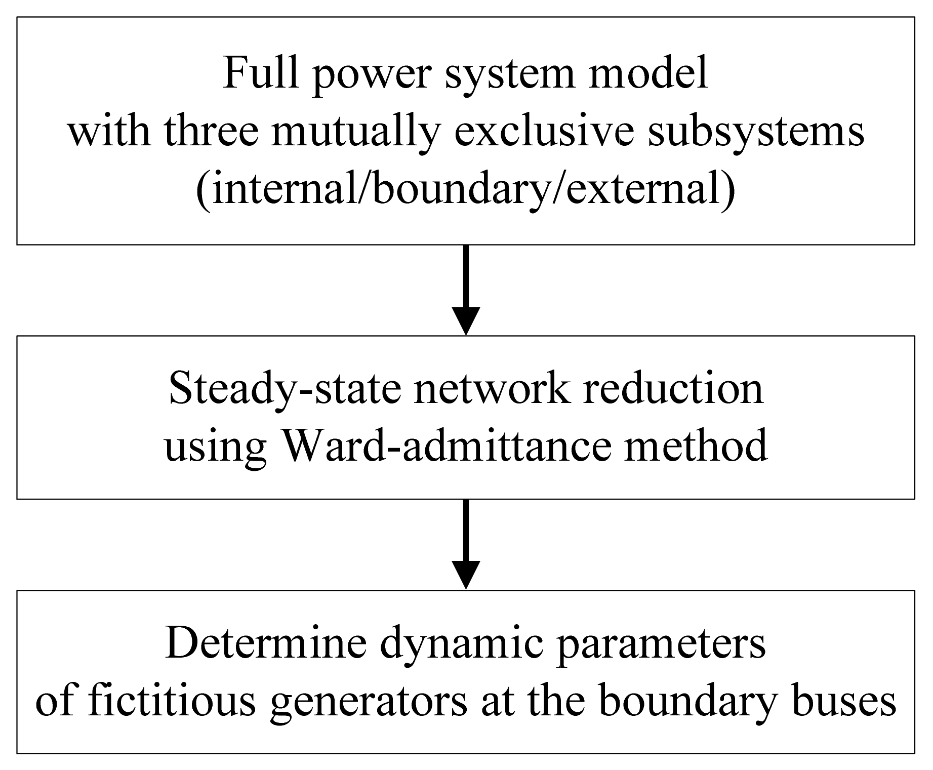
2. Methodology
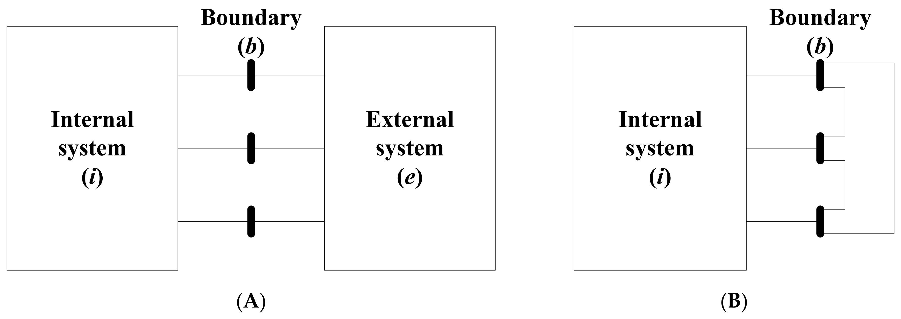
2.1. Steady-State Network Reduction
2.2. Dynamic Parameters of Fictitious Generators
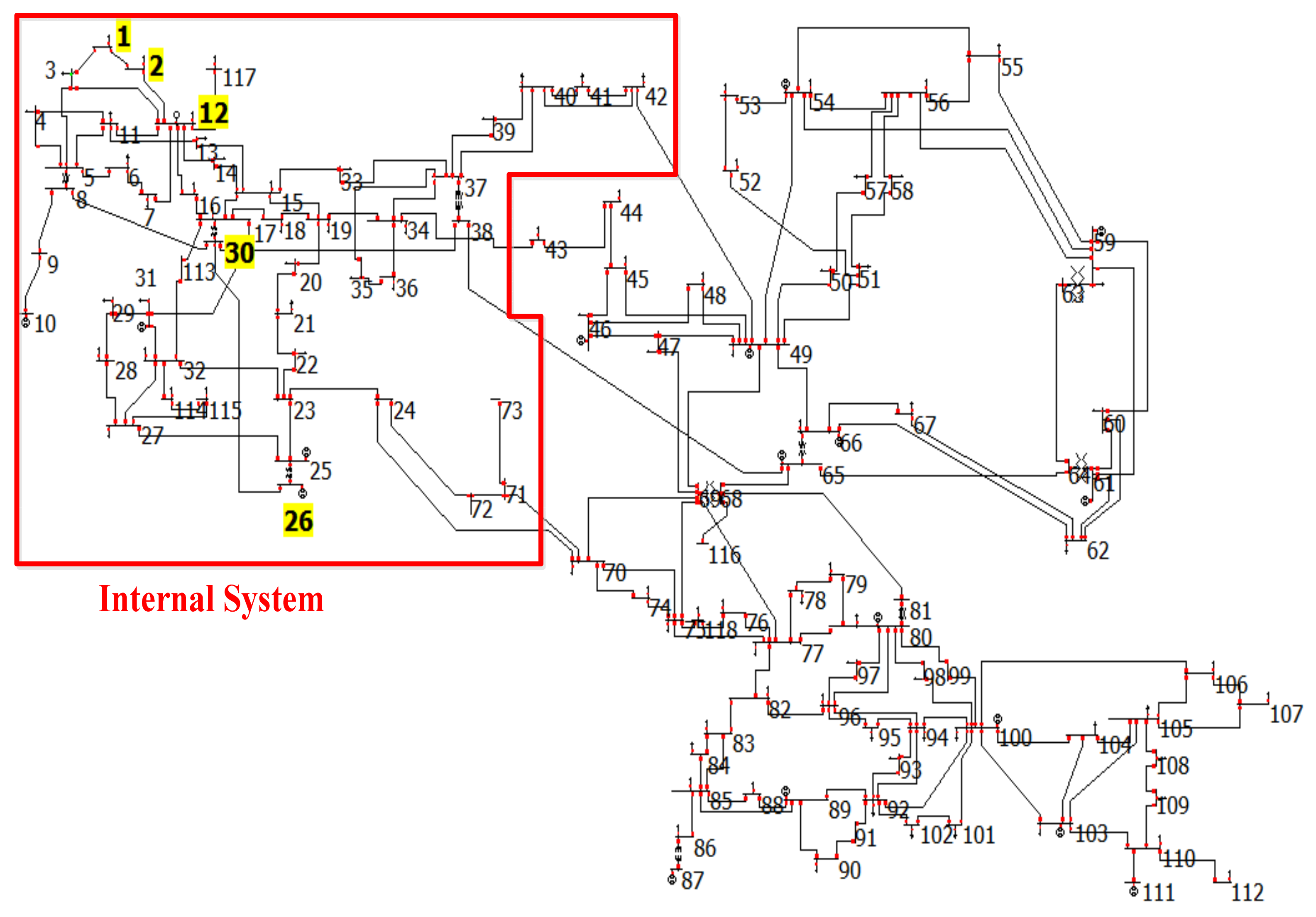
3. Case Study
3.1. Equivalent System
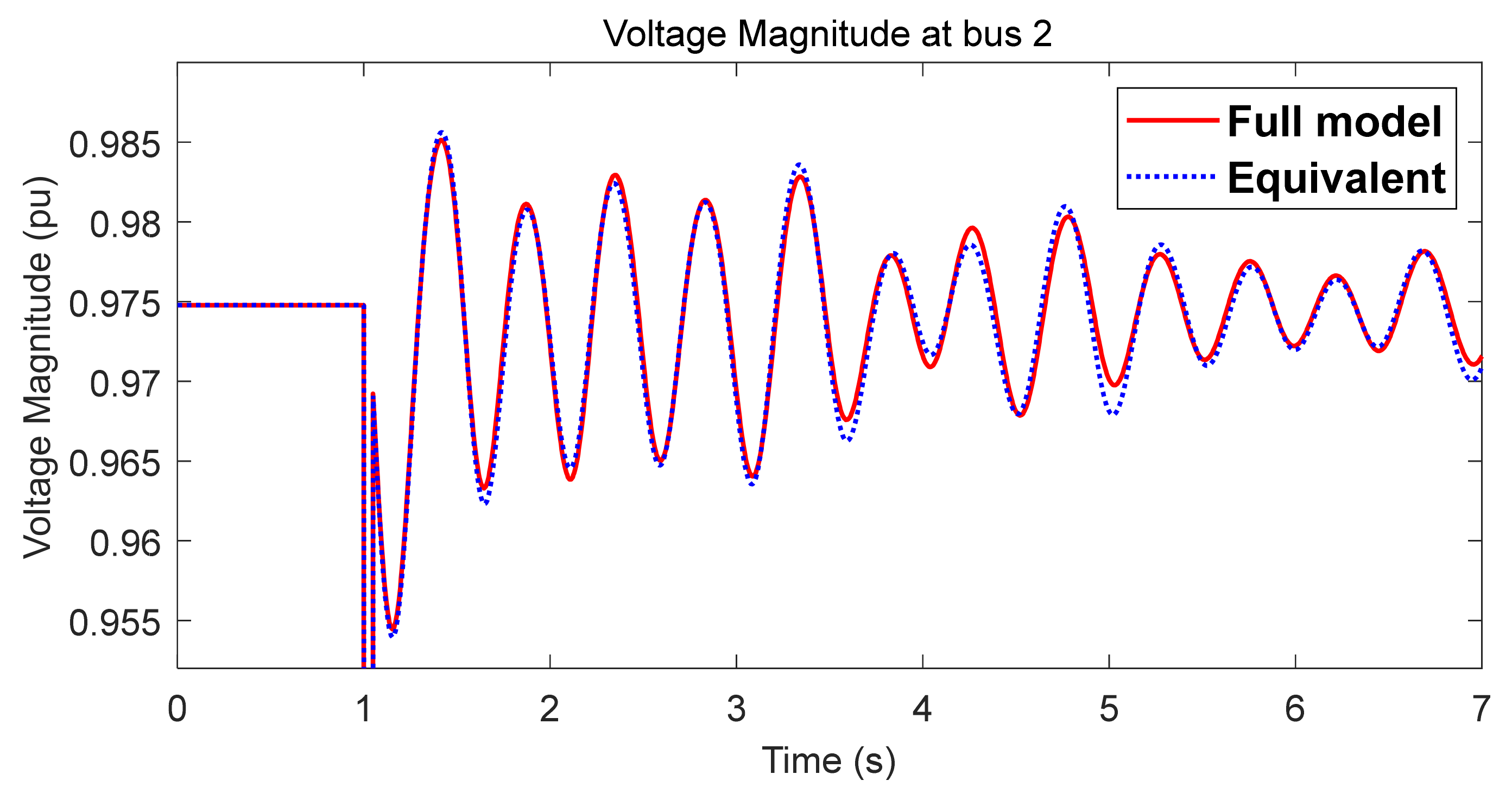
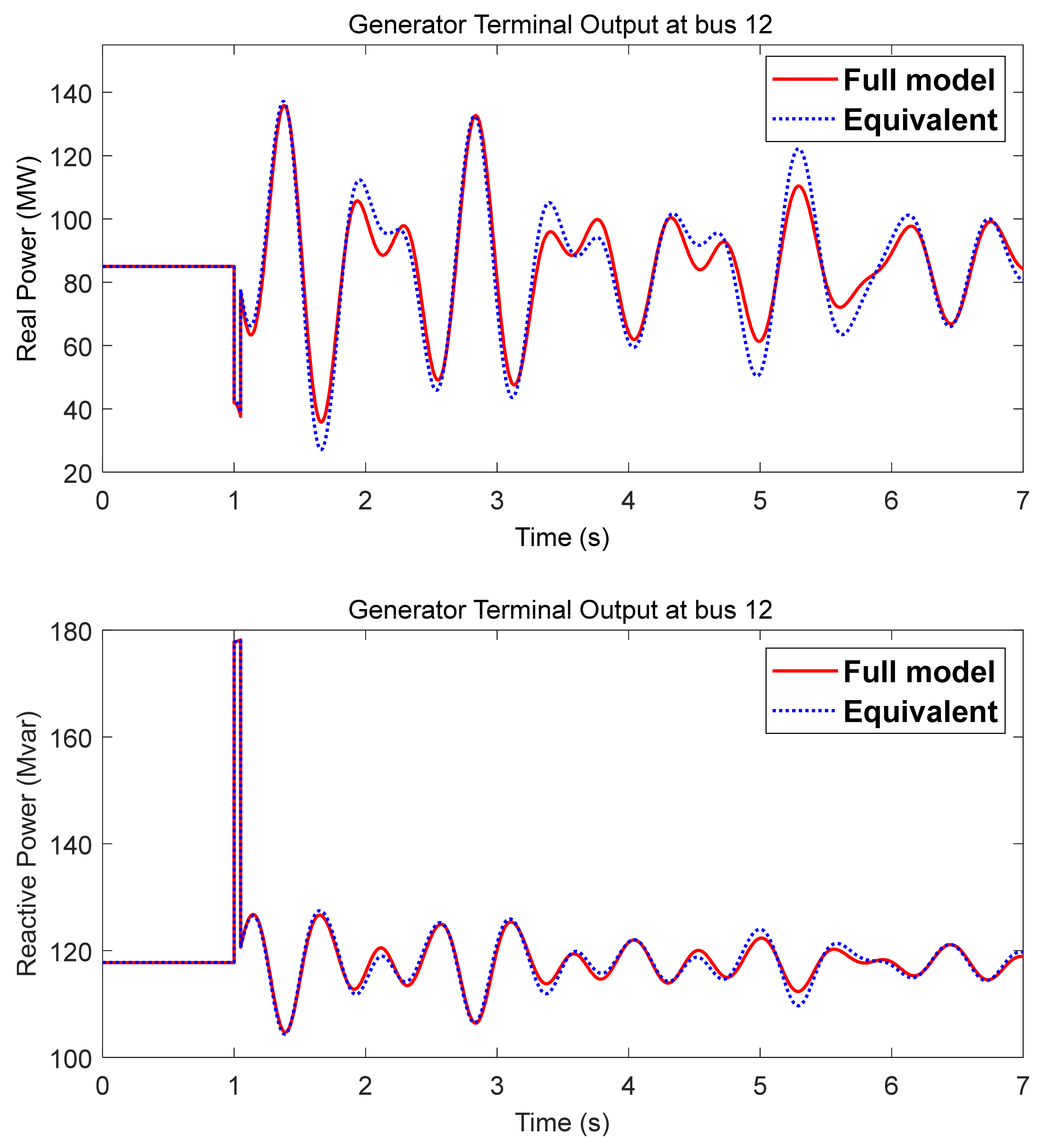
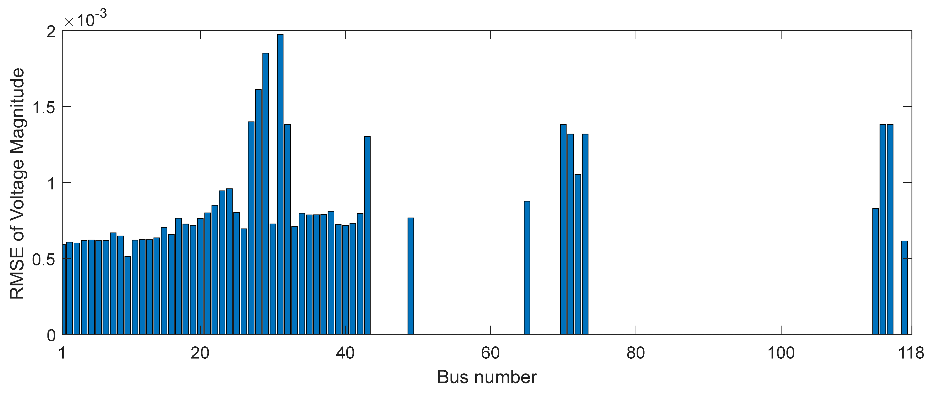
3.2. Bus-to-Ground Fault at Bus 1
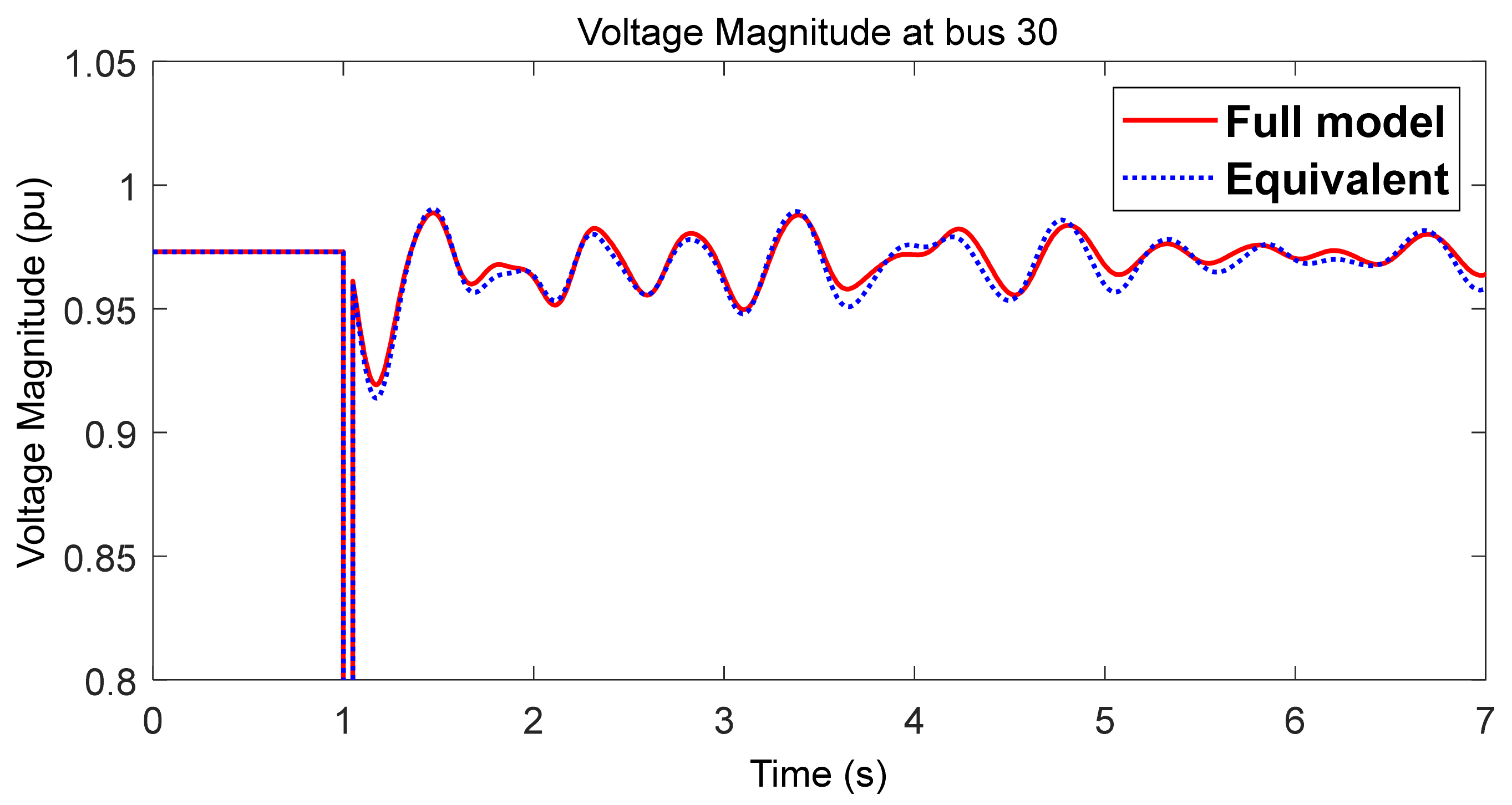
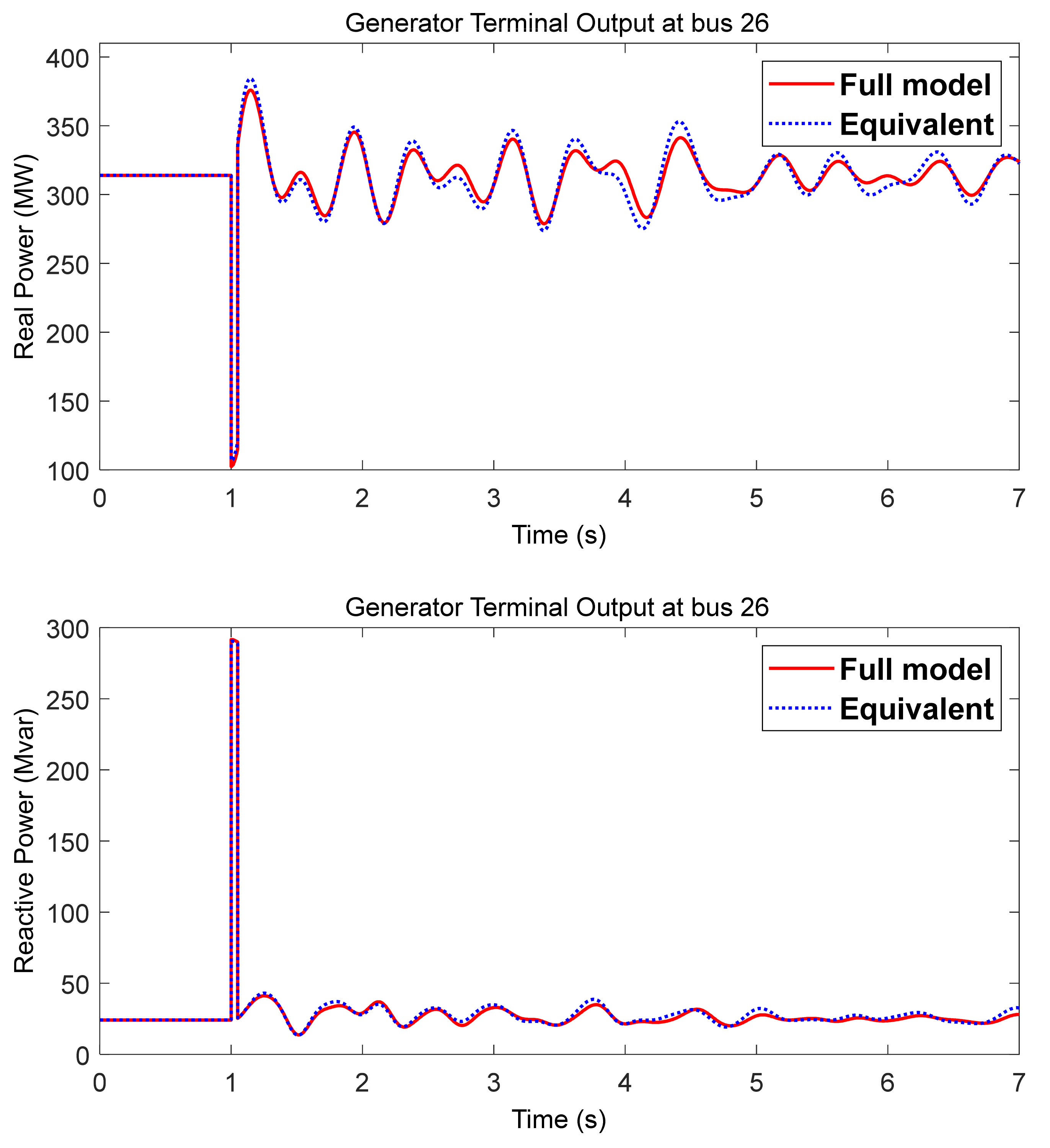
3.3. Bus-to-Ground Fault at Bus 30
3.4. Comparison of Computation Time
4. Conclusions
Author Contributions
Funding
Institutional Review Board Statement
Informed Consent Statement
Data Availability Statement
Conflicts of Interest
References
- Bose, A.; Overbye, T.J. Electricity Transmission System Research and Development: Grid Operations, Transmission Innovation Symposium: Modernizing the U.S. Electrical Grid. U.S. Department of Energy, April 2021. Available online: https://www.energy.gov/sites/default/files/2021-05/Grid%20Operations%20Bose%20Overbye_0.pdf (accessed on 10 December 2021).
- National Academics of Sciences, Engineering, and Medicine. Analytic Research Foundations for the Next-Generation Electric Grid; The National Academies Press: Washington, DC, USA, 2016; Available online: https://www.nap.edu/catalog/21919/analytic-research-foundations-for-the-next-generation-electric-grid (accessed on 10 December 2021).
- Xiong, J.; Acar, E.; Agrawal, B.; Conn, A.R.; Ditlow, G.; Feldmann, P.; Finkler, U.; Gaucher, B.; Gupta, A.; Hen, F.L.; et al. Framework for Large-Scale Modeling and Simulation of Electricity Systems for Planning, Monitoring, and Secure Operations of Next-generation Electricity Grids. In Proceedings of the Computational Needs for the Next Generation Electric Grid, Ithaca, NY, USA, 19–20 April 2011. [Google Scholar]
- Ward, J.B. Equivalent circuits for power-flow studies. Trans. Am. Inst. Electr. Eng. 1949, 68, 373–382. [Google Scholar] [CrossRef]
- Deckmann, S.; Pizzolante, A.; Monticelli, A.; Stott, B.; Alsac, O. Studies on power system load flow equivalencing. IEEE. Trans. Power Appar. Syst. 1980, 6, 2301–2310. [Google Scholar] [CrossRef]
- Gupta, A.P.; Mohapatra, A.; Singh, S.N. Power System Network Equivalents: Key Issues and Challenges. In Proceedings of the TENCON 2018—2018 IEEE Region 10 Conference, Jeju, Korea, 28–31 October 2018; pp. 2291–2296. [Google Scholar]
- Lo, K.; Peng, L.; Macqueen, J.; Ekwue, A.; Cheng, D. An extended ward equivalent approach for power system security assessment. Electr. Power Syst. Res. 1997, 42, 181–188. [Google Scholar] [CrossRef]
- Cheng, X.; Overbye, T. PTDF-Based Power System Equivalents. IEEE Trans. Power Syst. 2005, 20, 1868–1876. [Google Scholar] [CrossRef]
- Jang, W.; Overbye, T. Equivalent Line Limit Calculation Using Available Thermal Transfer Capability. In Proceedings of the Power and Energy Conference (TPEC), IEEE Texas, College Station, TX, USA, 28 February–1 March 2017. [Google Scholar]
- Lee, B.-G.; Lee, J.; Kim, S. Development of a Static Equivalent Model for Korean Power Systems Using Power Transfer Distribution Factor-Based k-Means++ Algorithm. Energies 2020, 13, 6663. [Google Scholar] [CrossRef]
- Annakkage, U.D.; Nair, N.K.C.; Liang, Y.; Gole, A.M.; Dinavahi, V.; Gustavsen, B.; Noda, T.; Ghasemi, H.; Monti, A.; Matar, M.; et al. Dynamic system equivalents: A survey of available techniques. IEEE Trans. Power Delivery 2012, 27, 411–420. [Google Scholar] [CrossRef]
- Ramaswamy, G.N.; Rouco, L.; Fillatre, O.; Verghese, G.C.; Panciatici, P.; Lesieutre, B.C.; Peltier, D. Synchronic modal equivalencing (SME) for structure-preserving dynamic equivalents. IEEE Trans. Power Syst. 1996, 11, 19–29. [Google Scholar] [CrossRef] [Green Version]
- Chow, J.H. Power System Coherency and Model Reduction; Springer: New York, NY, USA, 2013. [Google Scholar]
- Ju, P.; Ni, L.Q.; Wu, F. Dynamic equivalents of power systems with online measurements. Part 1: Theory. IEEE Proc. C Gener. Transm. Distrib. 2004, 151, 175–178. [Google Scholar] [CrossRef]
- Zhang, X.; Xue, Y.; You, S.; Liu, Y.; Liu, Y.U.S. Eastern Interconnection (EI) Model Reductions Using a Measurement-Based Approach. In Proceedings of the 2018 IEEE/PES Transmission and Distribution Conference and Exposition (T&D), Denver, CO, USA, 16–19 April 2018; Volume 2018, pp. 1–5. [Google Scholar]
- Powerworld Corporation. Available online: http://www.powerworld.com/ (accessed on 10 December 2021).
- Texas A&M University Electric Grid Test Case Repository. Available online: https://electricgrids.engr.tamu.edu/ (accessed on 10 December 2021).
- Kundur, P. Power System Stability and Control; McGraw-Hill: New York, NY, USA, 1994. [Google Scholar]
- Xu, T.; Birchfield, A.B.; Overbye, T.J. Creation of Synthetic Electric Grid Models for Transient Stability Studies. In Proceedings of the Bulk Power System Dynamics and Control Symposium, Espinho, Portugal, 27 August–1 September 2017. [Google Scholar]

| Bus No. | H | Xdp | D | Bus No. | H | Xdp | D |
|---|---|---|---|---|---|---|---|
| 10 | 5.66 | 0.059 | 3 | 65 | 7.41 | 0.067 | 3 |
| 12 | 9.97 | 0.22 | 3 | 66 | 7.41 | 0.067 | 3 |
| 25 | 8.24 | 0.139 | 3 | 69 | 5.26 | 0.053 | 3 |
| 26 | 6.01 | 0.096 | 3 | 80 | 5.26 | 0.053 | 3 |
| 31 | 12.37 | 0.247 | 3 | 87 | 12.37 | 0.247 | 3 |
| 46 | 12.37 | 0.247 | 3 | 89 | 4.64 | 0.047 | 3 |
| 49 | 8.24 | 0.139 | 3 | 100 | 8.26 | 0.095 | 3 |
| 54 | 9.97 | 0.22 | 3 | 103 | 9.97 | 0.22 | 3 |
| 59 | 7.93 | 0.153 | 3 | 111 | 9.97 | 0.22 | 3 |
| 61 | 7.93 | 0.153 | 3 |
| Buses | |
|---|---|
| Internal system | 1–42, 71–73, 113–115, 117 (49 buses) |
| Boundary buses | 43, 49, 65, 70 |
| Generator No. | H | Xdp | D |
|---|---|---|---|
| 43 | 1.4625 | 1.6138 | 0.371 |
| 49 | 31.9228 | 0.0374 | 10.221 |
| 65 | 68.7234 | 0.0114 | 25.2638 |
| 70 | 22.8318 | 0.0313 | 8.4201 |
| Model Used | Computation Time (s) | Ratio of Computation Time | |
|---|---|---|---|
| 118 buses | Full model | 0.436 | 1 |
| Equivalent (53 buses) | 0.328 | 0.75 | |
| 10,000 buses | Full model | 32.002 | 1 |
| Equivalent (1082 buses) | 1.978 | 0.06 | |
Publisher’s Note: MDPI stays neutral with regard to jurisdictional claims in published maps and institutional affiliations. |
© 2022 by the authors. Licensee MDPI, Basel, Switzerland. This article is an open access article distributed under the terms and conditions of the Creative Commons Attribution (CC BY) license (https://creativecommons.org/licenses/by/4.0/).
Share and Cite
Kim, S.; Overbye, T.J. Partial Y-Bus Factorization Algorithm for Power System Dynamic Equivalents. Energies 2022, 15, 682. https://doi.org/10.3390/en15030682
Kim S, Overbye TJ. Partial Y-Bus Factorization Algorithm for Power System Dynamic Equivalents. Energies. 2022; 15(3):682. https://doi.org/10.3390/en15030682
Chicago/Turabian StyleKim, Soobae, and Thomas J. Overbye. 2022. "Partial Y-Bus Factorization Algorithm for Power System Dynamic Equivalents" Energies 15, no. 3: 682. https://doi.org/10.3390/en15030682
APA StyleKim, S., & Overbye, T. J. (2022). Partial Y-Bus Factorization Algorithm for Power System Dynamic Equivalents. Energies, 15(3), 682. https://doi.org/10.3390/en15030682