1. Introduction
The main bus of a substation concentrates a large amount of power and many derivations to service electrical loads, making it an element of high importance for the reliability of the system. According to [
1], bus failures represent only 6–7% of all failures; however, their effects are as severe as multiple failures, which can result in system collapse.
For [
2], the buses are perhaps the most critical elements because they have high short-circuit levels and because their output from operation would cause a large number of forced shutdowns. This situation directly influences the reliability and continuity indicators of the system.
According to [
1], one of the techniques used for busbar protection is bus differential protection. Kirchoff’s current law governs the operation of busbar differential protection, based on which we consider that the sum of the currents entering a given node is equal to the sum of the currents leaving. In general, the differential protection of buses, regardless of the type of relay used, compares the currents that enter and leave the bus, and if there is a divergence in the difference in values, it opens the associated circuit breakers. Given the importance of transmission substations to the electrical power system, dedicated busbar protection is normally employed. In sub-transmission and distribution substations, bus protection is almost always provided as backup protection by the relays of lines connected to this bus.
By providing an IEC 61850 interface to the yard equipment, a new communication bus is introduced in the substation, the process bus, which connects the process level to the bay level. This architecture changes the design and operation guidelines of substations, bringing gains in costs, reliability, speed and enabling the implementation of differential busbar protection also in distribution substations.
The research carried out in this review seeks to present articles of interest to the use of IEC in busbar differential protection. For this, a search was carried out on differential protection of bars, where articles from 2017 and also previous articles with more than 10 citations were considered. In this way, the review is presented in two parts; one presents articles with classic methodologies of bus differential protection, and the other considers articles with methodologies using IEC 61850.
The aim of this research is to present a literature review on busbar differential protection using IEC61850. This review seeks to contribute to new studies and developments of protection systems based on the IEC 61850 standard, serving as a starting point for future substation digitalization studies.
To carry out the research, a protocol was elaborated, which sought to guide the research, aiming to answer the following questions: What is busbar differential protection? What are the existing busbar differential protection techniques? What are the advantages of implementing bus differential protection? What are the difficulties in implementing bus differential protection? What is the importance of IEC 61850 in bus differential protection? The search for articles was performed using the search string “Differential bus-bar protection” OR “Bar differential protection” OR “process bus” OR “bar differential protection techniques” AND “IEC 61850”. The following online databases were consulted: CAPES Journal Portal, IEEE Xplorer Digital Library, Scopus and Springer. The search result totaled 1007 related articles.
Figure 1 presents the annual publications for this theme.
After the treatment of articles, such as removing duplicates, reviewing titles, reviewing the abstract and selecting articles published from 2017 onwards, 28 articles of interest were selected.
Figure 2 presents the annual publication of selected articles.
Section 1 presents the introduction to the topic, highlighting the context of the research, its objectives and configurations.
Section 2 presents the articles found that present bus differential protection methodologies that do not use IEC 61850, which can be considered traditional methodologies.
Section 3 presents the articles found in the review that deal with the implementation, testing and development of new methodologies based on the use of IEC 61850.
Section 3.2 highlights the works that present IEC 61850 and deal with data synchronization.
Section 4 presents the discussion on the subject, demonstrating the main points related to the research, such as the number of annual publications on the subject and different performance times of the presented methodologies. Finally,
Section 5 presents the conclusions found in the development of this review.
2. Bus Differential Protection Methods—Traditional Methodologies
As mentioned earlier, Kirchoff’s current law is the principle of busbar differential protection. To monitor the currents entering and leaving the busbar, CTs are used. By stipulating a limit for the difference between the input and output of the busbar current, an actuation point for the differential protection is created. In this way, differential values above the predefined value are considered as an internal fault on the bus.
In the system shown in
Figure 3, a simple differential protection scheme is implemented, which is under normal load conditions. Secondaries of the CTs are connected to the differential relay. By the principle of Kirchoff’s law, the sum of the currents is equal to zero. However, to ensure that all secondary currents are compared on the same basis, all CTs must have the same transformer ratio, or the relay used must be equipped with multiple individual inputs.
When a fault occurs within the protection zone delimited by the CTs, that is, an internal fault (CASE 1), the short-circuit current is the sum of the currents measured by all the CTs. In this way, the differential current is different from zero; thus, the trip command must be sent by the relay to the circuit breakers of the elements connected to the busbar.
If a fault occurs outside the busbar protection zone (CASE 2), the total current towards the fault point is the sum of all the currents of the respective circuits connected to the busbar. For this situation, the differential protection must not act, as the sum of the currents that enter and leave the busbar is zero. Fast clearing of bus faults is very important; however, as external fault protection operation should be avoided to reduce the likelihood of a system disturbance [
3]. However, conventional CTs are susceptible to saturation, which can lead to malfunctioning of the differential protection, which is due to current distortion in the secondary CT.
For bus differential protection, high- or low-impedance relays are normally used. High-impedance relays can handle CT saturation quite effectively, but due to special CT requirements such as identical transformer ratios and physical wiring connection, their use is limited to static bus configuration only. Low-impedance differential relays have been widely used for static and dynamic bus configurations as they can easily handle dynamic zone reconfiguration and multiple CT ratios.
In [
4], a microprocessor relay with CT saturation countermeasure is proposed. This countermeasure prevents the breaker from tripping for a predetermined period during CT saturation. In [
5], a technique is proposed that uses positive and negative sequence models of the power system in a fault detection algorithm. For an internal fault, the impedances seen by all relays are located in the third quadrant of the impedance plane, as shown in
Figure 4a, while for an external fault, the impedance seen by the relay located in the faulted circuit is in the first quadrant, as shown in
Figure 4b. The impedances seen by the other relays are located in the third quadrant. This criterion can be used to distinguish internal faults from external faults in the bus protection zone. The classification between internal or external fault makes the method less susceptible to saturation than an algorithm based on the magnitude of the differential current.
According to [
6], the CT does not saturate immediately at the start of the fault. From this statement, the author uses the method of the difference between the time of appearance of the differential current and the time of occurrence of the fault. If the time difference is above the predetermined value, the differential current is triggered by CT saturation. The difficulty in this method is to accurately detect the time of occurrence of the differential current and the time of occurrence of the fault. The authors propose the analysis of the voltage signal with wavelet transform in order to detect the instance of the occurrence of the fault.
For [
7], methods that inhibit relay operation during CT saturation result in longer trigger times, while other methods do not guarantee correct operation under conditions of high and early CT saturation. When using voltage signals, the algorithms may not work correctly in case of voltage collapse. The techniques proposed in [
7,
8,
9] are based on the wavelet transform analysis of the transients generated by the fault, in order to distinguish between faults inside and outside the bus protection zone.
The approach of [
10] proposes a method for detecting CT saturation, based on virtual impedance. When considering
Figure 3, CASE 2, if the feeder CT is saturated, the value of the secondary resource impedance seen from the feeder can be calculated. Thus, at the beginning of CT2 saturation by an external fault, the current becomes small, and the impedance Z rises. From this variation, an external fault can be identified. For [
11], the bus protection principles can be classified into two types: based on power frequency components and transient components. Techniques based on frequency components need to eliminate impacts from transient components; thus, there is a need to filter out high-frequency components, a situation that affects the trip speed. The authors present a bus protection technique based on a transient directional traveling wave. When a fault occurs on one of the lines connected to the bus, the characteristics of the directional traveling waves on this line are different from the healthy lines. This fact allows the classification of the type of failure.
According to [
12], busbar protection methods based on traveling waves or transient currents have intrinsic immunity to CT saturation; this is due to fault type identification before saturation. However, identification failures may occur for faults with high resistances or with small starting angles, which is still difficult to achieve in practical engineering applications at high sampling frequency. From this point of view, the authors propose a technique based on the characteristic of the polarities of the superimposed currents of the transmission lines connected to the busbar. This technique assumes that the lines connected to the faulted bus have the same polarities for overlapping currents. However, when a fault occurs on any of the connected lines, the faulted line has the opposite polarity to the other lines.
The proposal of [
13] is an approach based on the principles of alienation and differential protection to assemble the adaptive logic. Without CT saturation, the differential principle sends the trip command. Upon detection of CT saturation, the alienation and differential principles are triggered to send the trip command. The coefficient of alienation is used to detect CT saturation, assess the degree of saturation and adjust the characteristics of the differential relays during saturation, thus preventing improper operation during external faults.
An improved bus differential protection scheme using differential current analysis using the S-Transform is presented in [
14]. The use of the S-Transform for complete visualization of the signal in the time and frequency domains allows the application of the support vector machine (SVM) classifier to differentiate between internal or external faults. For [
15], the identification of internal and external faults based on the SVM and elevation vector machine (RVM) presents as its main limitation the difficulty in providing satisfactory results due to the behavior of the kernel function. Thus, the authors propose the use of a new fault classification scheme using a logistic regression (LR) classifier.
Reference [
16] presents a methodology based on characteristics of partial operating currents, such as magnitude and angle, which the author calls partial operating current (POC). To differentiate internal and external faults of protection zones these characteristics are used.
For [
17], the fault clearing time can be divided into protection scheme operating time and fault current interruption time. Thus, there are proposed alternatives for algorithms based on the wavelet transform to decrease the operation time of the protection scheme. Despite their gain in speed, these algorithms are not able to adequately deal with the evolution of external to internal faults. Thus, the authors present a new wavelet-based low-impedance bus differential protection algorithm, where, from the fundamentals of differential protection based on instantaneous current and the 1-of-1 and 2-of-2 trip logics, mapped in the wavelet domain operate with current energy from operating and restraining wavelet coefficients. For the authors, in the case of internal and evolutionary external-internal faults, the results demonstrate that the protection function provides ultra-fast tripping, which guarantees safety for normal load and also for external faults.
In [
2], a bus differential protection scheme based on the concept of instantaneous power is presented, where the proposed trip logics are based on logic 1-of-1 and 2-of-2. In their work, the authors present a new harmonic power restriction strategy to be used during external faults.
In [
18], the authors present an improvement of the generalized alpha plane (GAP) formulation, presented by [
19], bringing as main feature the control over the fault settlement region (FSR) in the right half of the alpha plane, that makes it possible to use an operational resource instead of a constraint resource, as traditionally performed.
3. Implementation, Testing and Methods of Bus Differential Protection Based on IEC 61850
IEC 61850 aims to improve the interoperability of equipment used in substations, reduce costs and simplify operations. For [
20], systems based on IEC 61850 become more flexible and secure, uncomplicating data transfer within the substation and providing seamless connectivity between IEDs, merging units (MUs) and circuit breakers. For [
21], the standard provides, in addition to gains in the interoperability of the system, an improvement in the level of operation, security stability of the substation automation system, reduction in the consumption of human resources and materials in inspection, and also maintenance. According to [
22], in addition to improving automation, communication within the substation offers opportunities for improvement and development of conventional protection schemes. For [
23], the first edition of IEC 61850 focused on networks and communication systems in substations, while the second edition seeks to cover networks and communication systems for energy utilities. Thus, the new standard requires, at the process and station levels, the integration of protection, control, measurement and monitoring functions. Already [
3], considers one of the most important benefits provided by IEC 61850, the fact of the possibility of installing the MU next to the breaker cabinets. Installing the MU next to the circuit breaker significantly reduces the load on the CTs, and consequently reduces the possibility of their saturation. Other benefits of IEC 61850 can be cited: lower expenses with installation, wiring, commissioning and maintenance; adaptable bus configuration; use of different CT ratios; considerably minimizes susceptibility to CT saturation; lower risks of open secondary CT circuits and viability of implantation in distribution substations. The works found in the literature that make use of IEC 61850 are presented below.
3.1. Research on Differential Protection of Bars Employing IEC 61850
In [
20], the authors present a method to analyze the reliability of a digital SE based on IEC 61850. The authors use reliability block diagrams to verify the reliability of the SE components and the state space approach to study the effects at the substation level. According to the authors, from the results of the analysis, important information is provided to analyze the reliability of the SE and the effects of its failure on the rest of the power system. The authors describe the substation architecture based on IEC 61850 with the different components and their descriptions.
Figure 5 represents its architecture.
Elements/Devices
The main elements/devices that are part of the substation based on IEC 61850 are:
Merging unit (MU): unit used in conjunction with current transformer (CT) or potential transformer (PT), to monitor the operating status of network components. The MU digitizes analog signals and sends them to intelligent electronic devices (IEDs).
Intelligent electronic device (IED): device that performs protection, measurement and control functions with advanced local control intelligence and has the ability to monitor processes. The FDI has the following categories: protection IEDs (Prot IEDs), control IEDs (Ctrl IEDs) and breaker IEDs (Brkr IEDs).
Communication bus level structures
The communication buses found in substations based on IEC 61850 are:
Process bus: the process bus makes the connection between the process level and the bay level, allowing the sending and receiving of messages between both.
Station bus: the station bus makes the connection between the station level and the bay level, allowing the sending and receiving of messages between both.
The authors of [
3] present two main types of substation busbar protection: (1) based on remote (peripheral) units that perform the interface with the process and a central unit that performs the busbar differential protection function and (2) based on remote (peripheral) units that perform the process interface and establish the fault direction and a central unit that performs the directional bus comparison protection function. The remote units can be multifunctional IEDs; however, for systems based on IEC 61850, the MU is used. The article analyzes such systems and deals with methods and tools to test them.
For [
24], the distance or overcurrent relays used as a backup scheme present deficiencies in the protection schemes, such as the staggered adjustment rules, which result in actuation delays generally of 0.5 to 1.5 s, a situation that seriously threatens the equipment and even the stability of the energy systems. Thus, the authors propose a SE area relay to replace the traditional backup protection system. Thus, coordination of backup protection tuning is simplified with the shortest delay time. The fault component location algorithm utilizes the current differential principle with a self-adaptive restraint instrument. The algorithm was implemented in a prototype based on IEC 61850 standards, where tests were performed using a digital simulator in real time, together with a communication simulator. As a contribution, the authors propose a new architecture of the Smart Grid Protection System. The new architecture consists of three parts: unit protection (UP), substation area protection (SP) and wide area protection (WP).
Figure 6 shows the scope of each part.
The authors point out that the UP serves as an independent primary protection, while the centralized SP, also known as substation-area backup protection (SBP), replaces the traditional local backup relays. WP performs remote backup protection and stability adjustment based on scattered SPs, rather than based on the phasor measurement unit (PMU) and wide area measurement system (WAMS). One of the advantages of this new architecture is the improvement in the performance of the backup protection system provided by the SBP through the sharing of information throughout the substation and neighboring substations. Thus, the information required by the SBP includes sampled values, circuit breaker (CB) states and UP actuation signals. The application of the IEC makes it possible to exchange this information through a generic object-oriented substation event (GOOSE) and sample values (SVs), within the substation and between substations. The authors conclude from real-time and communication simulators that the methodology can identify the type of fault, not being affected by CT saturation, inrush current, fault resistance or abnormal communication.
In [
25], the authors present the necessary steps for the migration from conventional substations to digital substations, where virtual services are run by a software-defined control system. Thus, substations adapt a large quantity of distributed energy resources (DERs) to the new situation, which changes the operational requirements and the feeder energy flow, control and protection functions. For the authors,
Figure 7 represents the digitally enabled version of a substation. In this architecture, data are shared through the communications network, resulting in the availability of digital information on the behavior and status of the system, and the control of primary equipment is carried out through digital interfaces.
According to the authors, the main component of this architecture is the substation edge device. It is a processing platform that runs software services using a container-based architecture. Therefore, any application can be independently developed, prototyped and tested quickly, such as wide area monitoring, DER management and asset performance management (APM) applications. There is no need for a firmware update or impacts on services or apps that are already running when loading new apps. This advance requires two distinct steps: the first is for the substation to become fully digital, that is, to implement the process bus; the second is digitally enabling using an edge device that supports a software services architecture. Next, peripheral devices deploy standard gateway functions first and then new power systems and control applications. The future trend will be the development of protection functions as applications, supported by a real-time operating system.
In [
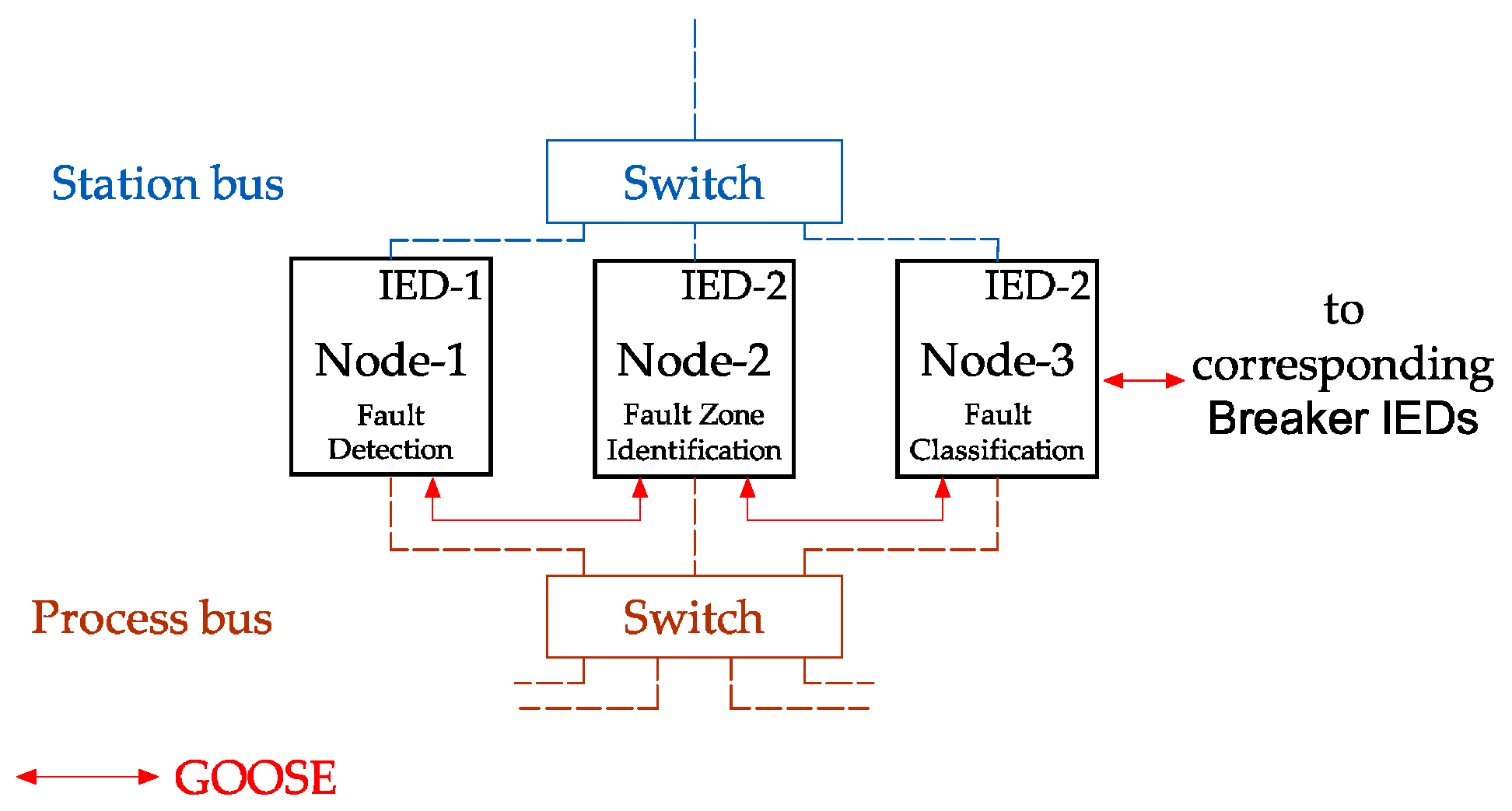
26], the authors classify busbar protection schemes into two categories: The first category is composed of methods based on energy frequency components. According to the authors, schemes based on frequency components are prone to CT saturation, and given the need for phasor computation, they add a significant delay in fault clearing. The second category of protection methods is based on transient frequency components. In this category, the speed is significantly higher, as they are based on instantaneous voltage and current. However, some methods cannot identify faults where the current magnitude is small, as in the case of high-impedance faults. Thus, the authors propose a new bus protection method based on the wavefront at the CT locations on all lines connected to the bus. From the comparison of the polarity and the magnitude of initial WT modulus maxima (WTMMs) that appear after the start of the fault, it is possible to identify between internal and external faults.
In the proposal, the authors implement the process bus based on Ethernet. Fault detection, fault classification and zone identification are implemented as three separate nodes. Node-1 detects the magnitude of the WTMMs observed in the SV, greater than a preset value, and activates node-2 via GOOSE message. From the analysis of the polarity of the WTMMs, the IED-2 classifies between internal or external failure and then activates the IED-3 in the detection of a fault on the bus, as shown in
Figure 8.
For the authors, the method has the following advantages: greater sensitivity during internal faults on the bus and greater stability for external faults; immunity to TC saturation, as external faults are detected based on the instance of initial WTMMs, which appear before the onset of TC saturation; greater stability against nearby external faults and greater sensitivity in the case of internal faults with high resistance and the lack of complex post-fault data processing.
For [
27], the fact that low and high-impedance current differential methods require voltage and current calculations results in the exclusion of the possibility of subcycle tripping, and the need for filtering ends up adding a significant delay to the protection. Based on these facts, the authors propose a bus zone protection method based on the Park transform (dq). In this way, the low-impedance bus zone differential protection method is based on d-axis components. According to the authors, the approach becomes simpler for busbar zone protection, starting to work more efficiently with fewer data, since only the dq components of the current are monitored instead of the data of all phases. For the authors, the use of dq components in fault analysis has the following advantages: the response of the dq components under fault conditions is greater than the components of all phases, since the frequency of the dq components changes from 0 (DC values) to twice the frequency (2ω) instantly with the onset of the fault; shorter processing time results in shorter response time in case of internal faults in the bus; simpler solution with lower investment cost, as it only requires a relay with a d-axis current component instead of segregated relays in terms of three-phase current components; greater savings for the concessionaire, as it uses a smaller number of circuits without the need for communication between the relays, which is due to the fact that only one relay is used; d-axis components can be examined in terms of power frequency components, which allows conventional CTs and PTs to be used without any special requirements; and the simplest numerical analysis for distinguishing dq components between normal and fault conditions, which allows its implementation on existing hardware. To validate the method, the authors performed simulations considering internal and external faults, faults considering CT saturation, performance in noisy conditions, performance in the presence of a decomposing DC component, high-impedance faults (HIFs) and evolution from external to internal faults.
3.2. Research Focusing on IEC 61850 and Dealing with Time Synchronization
In Reference [
21], the authors analyze the communication between a non-conventional instrument transformer (NCIT) and the current differential relay with IEC 61850 support. The method is based on phase-locked loop (PLL) technology, and its objective is to implement time synchronization between MU and the protection IED in order to correct the existing non-deterministic delay in the communication network.
In [
28], the authors present the hardware implementation of a process bus communication network, based on IEC 61850-9-2 typical for digital protection systems. Its objective is to analyze the SV estimation algorithm implemented in transmission line distance and bus differential protection IEDs, performing tests in several scenarios, such as power system failure and the loss or delay of SV.
In [
22], the authors present an overlapping directional comparison method for bus protection. The technique uses the process bus based on IEC61850. The operating principles of this method resemble the conventional principles of directional comparison bus protection; however, the voltage and currents are converted into data packets in the MUs and are sent through the communication network to the relay with support for IEC61850-9-2. Upon receiving the data, the relay performs the protection functions to decide upon sending the trip. Using GOOSE messages on the process bus, the relay sends the trip signal to the IEDs or MUs. According to the authors, the directional comparison bus protection unit (DCBPU) method is less sensitive to packet loss and delay and does not require precise time synchronization, as overlapping directions are used for decision making instead of current differential.
In [
29], a study of the influence of the synchronization error in two LAN-based digital substation protection methods is presented: the first based on differential current and the second on distance protection. For the study, the authors propose a substation model constituted by IEDs supported by IEEE 1588 PTP. Its structure consists of collaborative IEDs connected to the communication network. The collaborative IED is a core building component that contains the functions of collaborative protection and time synchronization.
The proposal for differential protection refers to a main block for detecting faults and auxiliary blocks for handling the desynchronization of collected data. The fault detection main block is based on differential current. This block detects a fault in the SE, while the measurement alignment block based on PTP delivers the properly synchronized data. The authors highlight the need for a master–slave-based time synchronization protocol to ensure precisely synchronized operation of the detection units, where the desynchronized data from each detection unit are compensated by the application of signal processing techniques, as extra/interpolation of the measured value. From the simulations, the authors point out that as the synchronization error increases, the incorrect operation of the differential protection scheme also increases. The data show that a time synchronization error of 250 us leads to about 7% of protection scheme malfunctions for a situation of 100% load. The simulations also demonstrate that the use of a larger load becomes more susceptible to problems related to time synchronization than the use of a smaller load because a larger fault current results in an error-prone calculation of the differential current. The authors conclude that accurate and fault-tolerant time synchronization is of paramount importance for substation digitalization.
In [
23], the authors propose a centralized busbar protection scheme based on IEC 61850 for distribution substation. The method takes into account the desynchronization problem and presents as its main causes measurement time errors and synchronization error. To compensate for time synchronization errors, the authors propose the use of Lagrange’s theorem. From this theorem, time measurement errors and voltage angle differences between the IEDs are compensated. In the proposed work, SV is used to exchange phasor data. When comparing traditional methods of busbar protection with methods based on IEC 61850, the authors point out that traditional methods are naturally synchronized, while methods based on IEC 61850 require care with data synchronization.
After the data desynchronization compensation, the measurement time error compensation is performed with the Lagrange interpolation polynomial. In the second step, the voltage angle differences between the IEDs are adjusted, thus compensating for the time synchronization. Finally, after data synchronization is complete, bus differential protection is applied. The proposed methodology was tested in an environment containing a real-time digital simulator, a central IED and three local IEDs. The synchronization errors were generated by an SNTP time server.
Tests were performed for load fluctuation as well as internal and external failure situations. For synchronization errors of up to 0.5 ms, the differential current, for an external fault, remains below the pick-up current; however, for higher values, the differential current exceeds the values of the pick-up current. The authors consider the results satisfactory, since the data desynchronization compensation substantially reduced the errors related to the differential current, and as a result, it avoided the erroneous operation of bus differential protection.
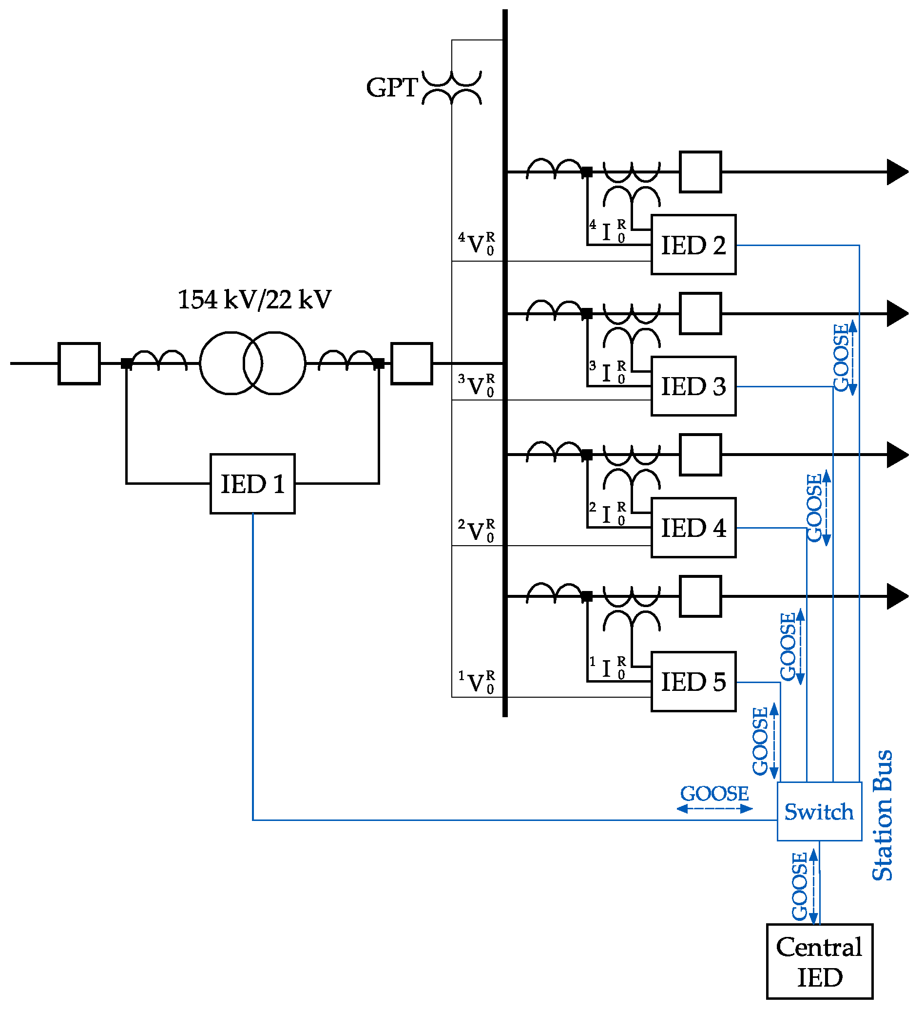
In [
30], a method of centralized protection based on IEC 61850 against single line-to-ground faults in ungrounded distribution systems is presented. According to the authors, single line-to-ground (SLG) faults can be detected on buses and feeders, even if the IEC 61850 data are desynchronized. With the impossibility of calculating the zero sequence current from the phase currents, the methodology makes use of a ground potential transformer (GPT) installed on the busbar to measure the zero sequence voltage.
In the proposed method, the IEDs installed on the feeders send zero sequence voltage and current signals to the central IED, and the signals are sent via GOOSE messages, as shown in
Figure 9.
The magnitudes and angle differences are used by the central IED to identify an SLG fault on the feeder or busbar. The GPT supplying the zero sequence voltage signals to all the IEDs can compensate for the data desynchronization from the calculation of the zero sequence angular difference. In order to validate the proposed method, the authors performed fault simulations on one of the feeders and on the substation bus. In both situations, the values of fault resistance were varied. According to the authors, the results obtained demonstrate that the method presented the expected results.
4. Discussion
It can be seen that the major concern in traditional busbar protection methods is centered on the classification of the type of fault, that is, whether it is an internal or external fault. This is due to the susceptibility to CT saturation in an external fault, a situation that often leads the differential protection to operate erroneously. Another observation that can be seen in
Table 1 is that the vast majority of works on bus protection are intended for transmission substations; this is due to their cost and implementation complexity.
When considering traditional busbar differential protection methods, the works found in the literature present as their main contribution the classification of the type of fault. It can be seen in
Figure 10 that the works with the highest number of citations [
6,
7,
12] seek to classify the type of fault using wavelet transform, Fourier analysis and traveling waves techniques, respectively. This demonstrates the importance and diversity of the research already carried out.
The works based on IEC 61850 present as main problems of differential protection the loss of packets on the process bus and data desynchronization. This statement can be seen when analyzing
Figure 11, where the works with the highest number of citations deal with the investigation of a corrective measure for loss or delay of SV and a bus protection based on an IEC61850 process bus, which, according to the authors, is less sensitive to packet loss and delay.
In traditional methodologies, the fault type classification time depends on the type of methodology used and may vary from 2 [
2] to 7.6 ms [
5]. Methodologies based on IEC 61850, on the other hand, can present an operating time in the order of 3 [
26] to 10 ms [
27], when necessary to compensate for delay or packet loss. Even with a slightly higher response time, busbar protection methods based on IEC 61850 bring significant advantages compared to traditional methods, one of which is the feasibility of implementing busbar differential protection in distribution SEs. This fact can be seen in
Table 1, where the increase in work on differential protection in SE distribution based on IEC 61850 is notable. These are themes that are gaining prominence among researchers.
5. Conclusions
This review presents the articles related to the use of IEC in the differential protection of buses for distribution SEs, based on articles published from 2017 and previous articles with more than 10 citations. With the bibliographic review, it is possible to verify the main problems for the protection of the busbar, that is, the classification of the type of fault during the saturation of the CT in the methodologies considered traditional, and the desynchronization of data in methodologies based on in the IEC. It can be seen from
Table 1 that most of the traditional protection methodologies found in the literature are intended for transmission SEs. This is justified by the high cost and complexity of implementing bus differential protection in distribution SEs. However, with the advent of IEC 61850, research seeks to encompass and demonstrate the feasibility of applying busbar protection in distribution SEs.
Methods based on this IEC overcome the main problem of traditional methodologies, which is CT saturation. However, the new challenges are problems related to communication, mainly packet loss/delay, corrupted packets and data desynchronization, among others. These challenges are relevant, deserving attention in future research.
Finally, this review contributes to the development of new busbar protection methods based on the IEC 61850 standard, serving as a starting point for substation digitalization studies.


 ,
, 


