
Access to Deposits as a Stage of Mining Works


Abstract
1. Introduction
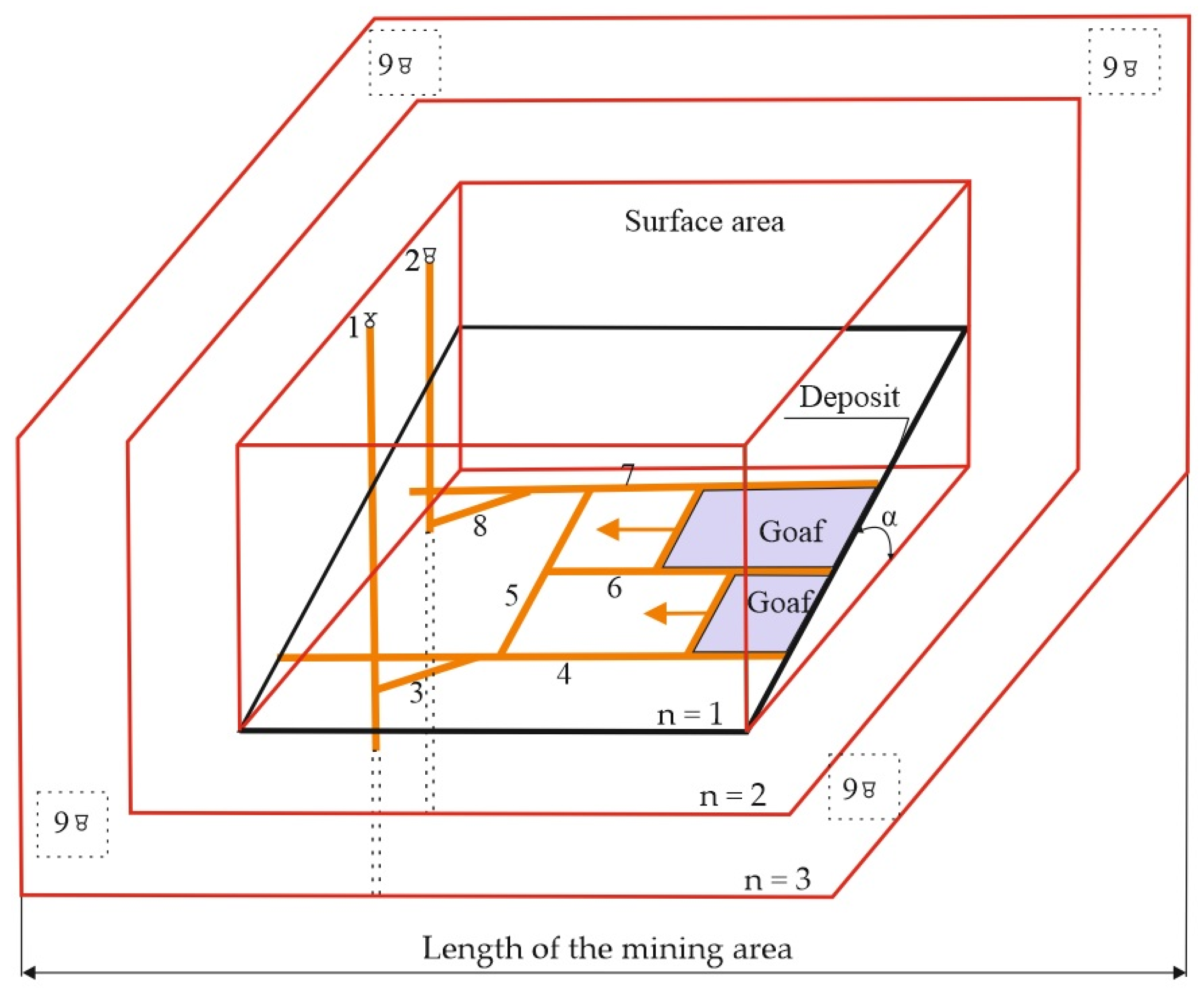
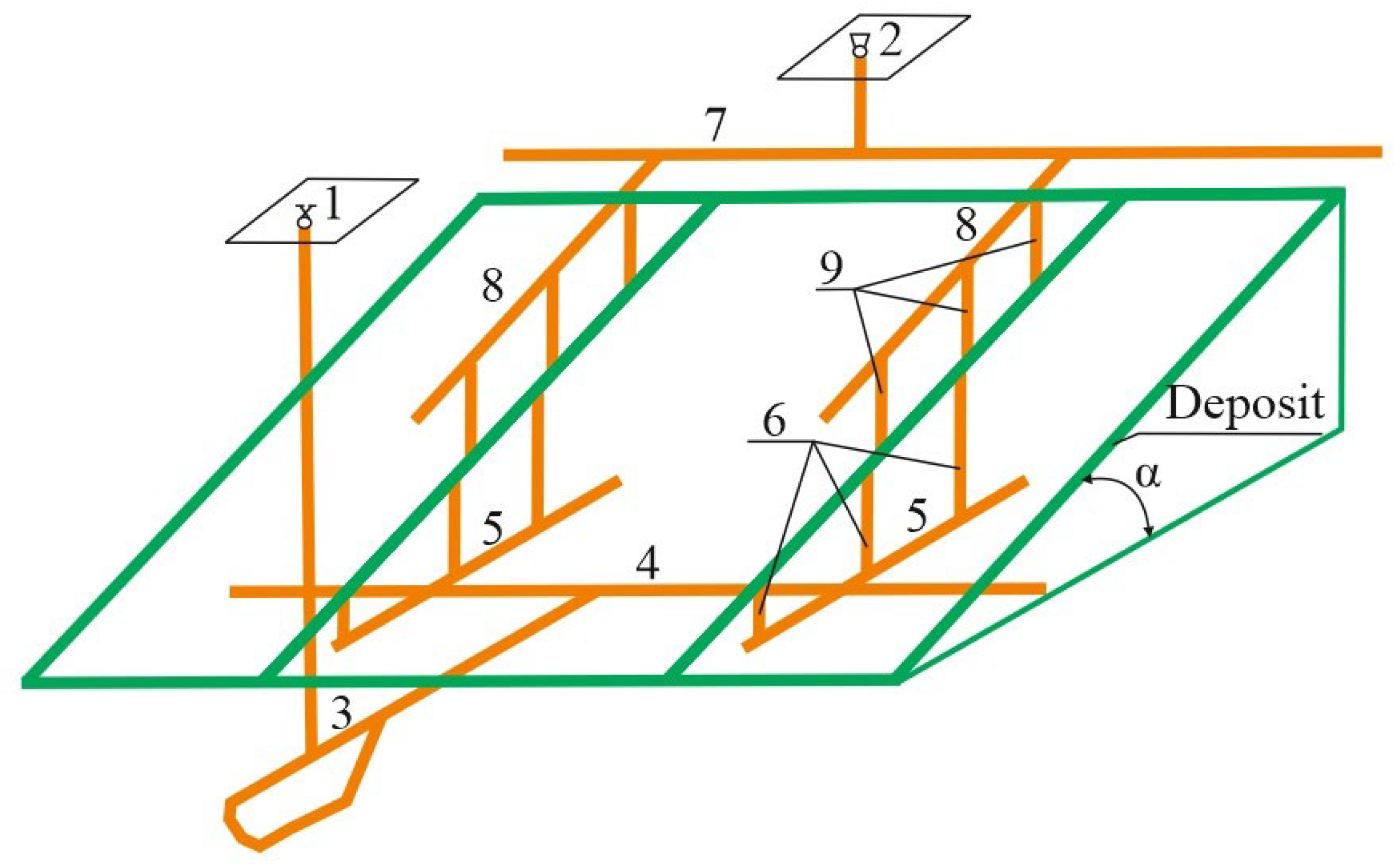
Mining Area
- L—length of the mining area;
- n—number of levels.
- a—operational losses;
- b—output dilution.
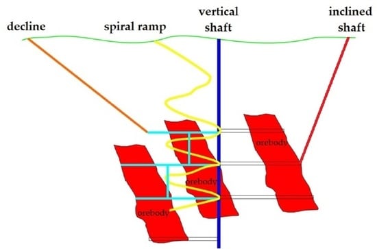
2. Ways of Access of Excavations
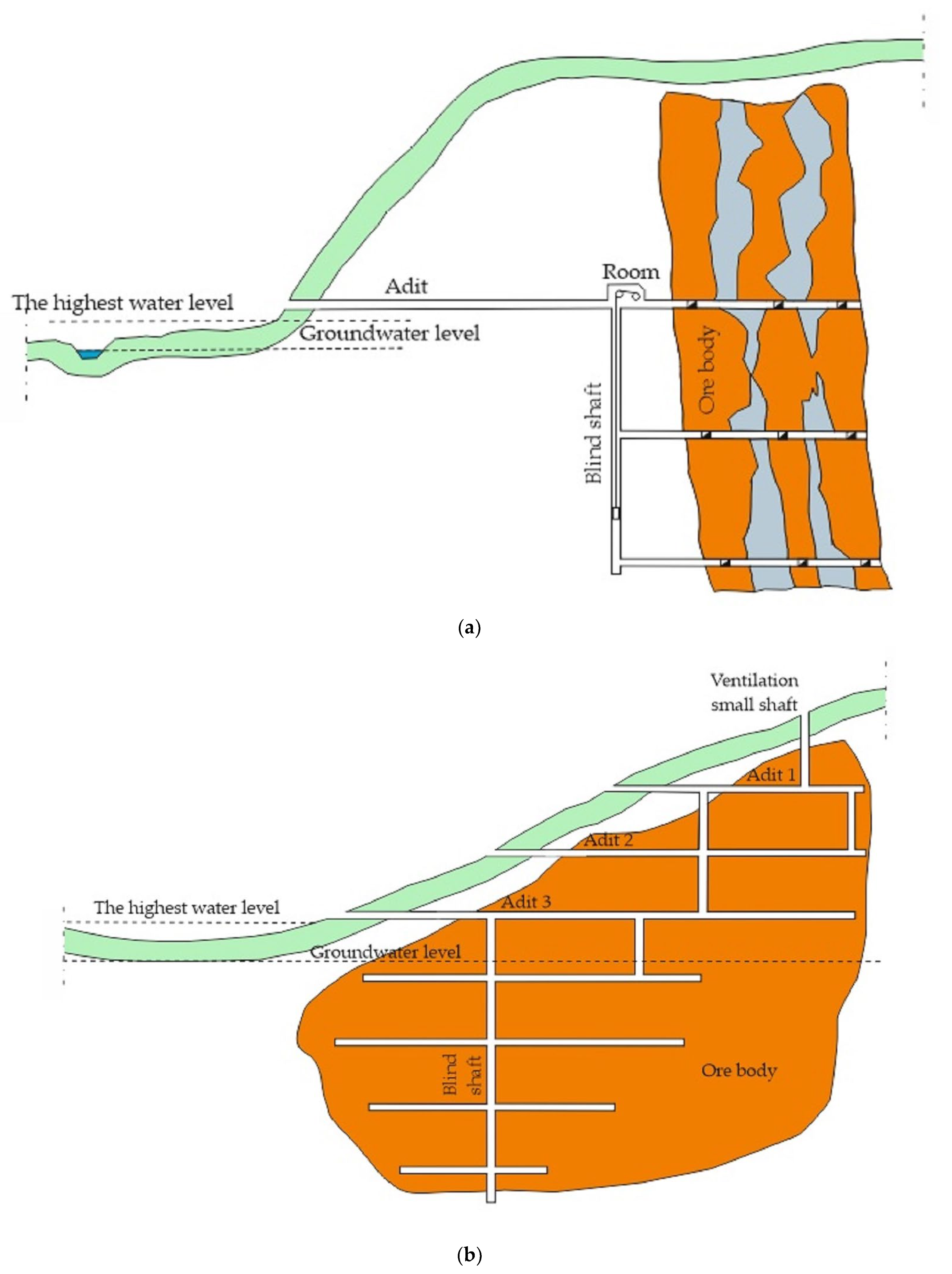
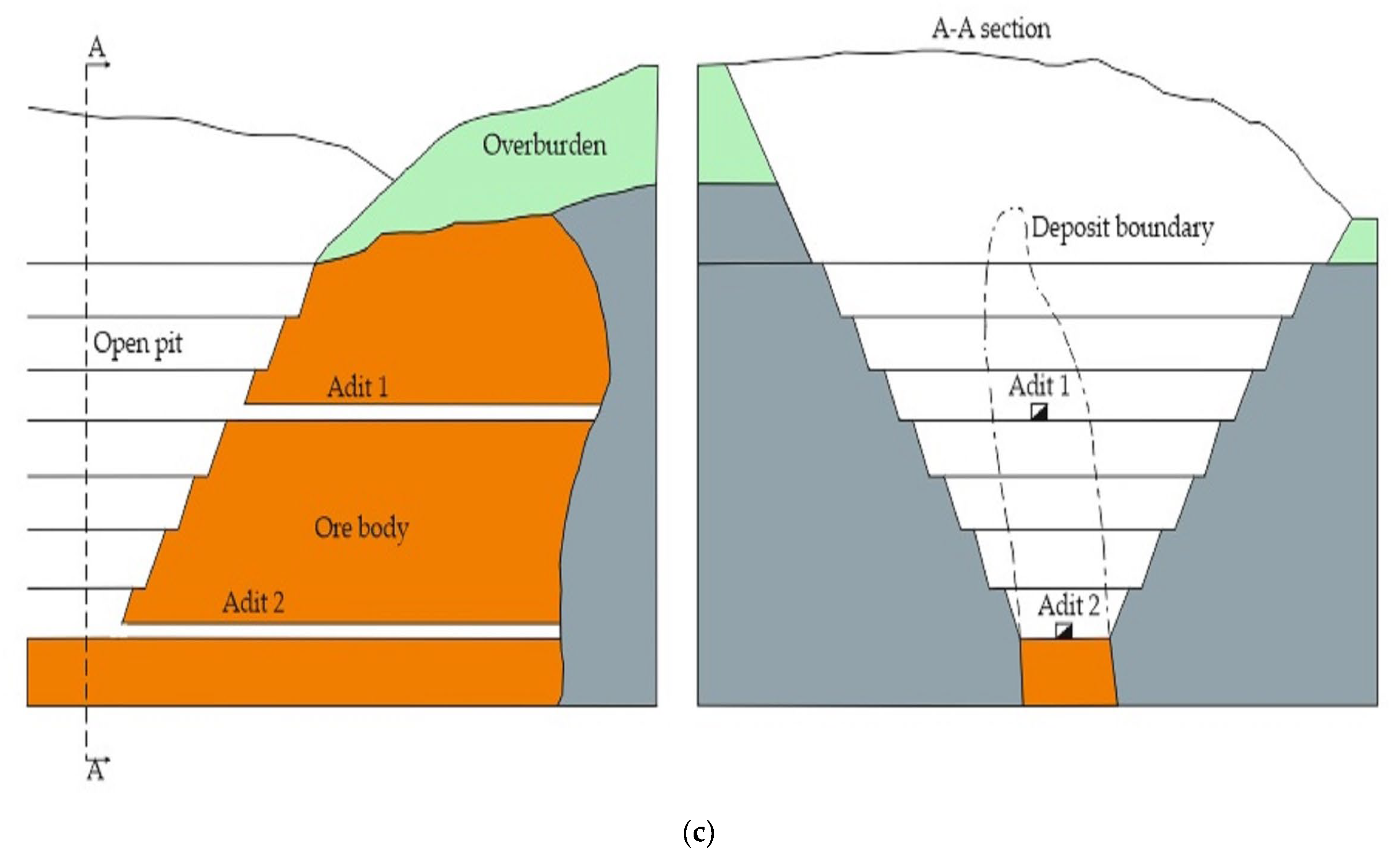
2.1. Access by Means of Adit
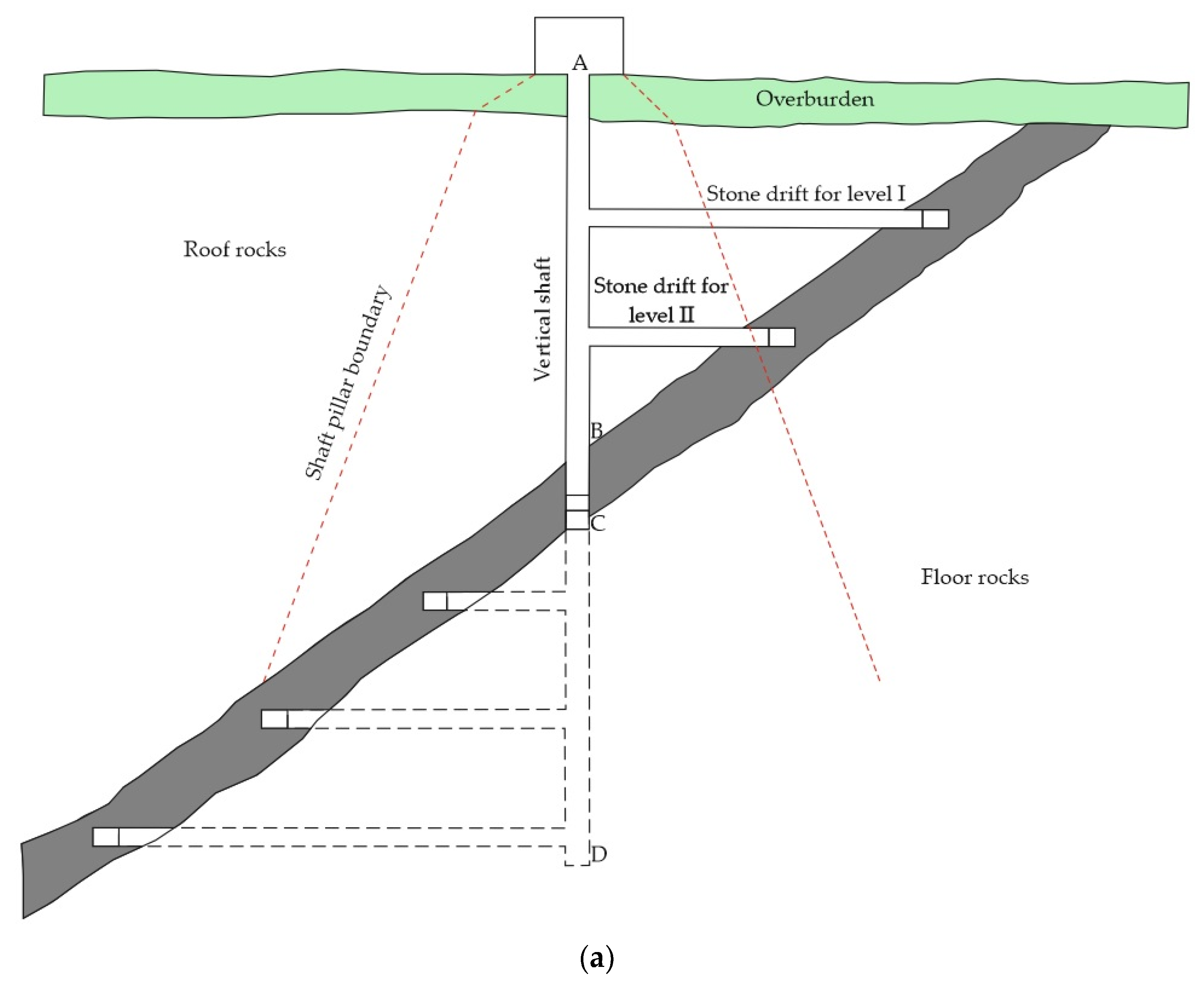
2.2. Access by Means of Vertical Shaft
- Keeping the shaft vertical is easier than inclined, as the rock mass pressure on the lining is less;
- The vertical shaft, which accesses the deposit at the same depth as the inclined shaft, has a shorter length;
- The permissible speed of hoisting of output in vertical shafts is higher than in inclined shafts, and therefore the transport capacity of the vertical shaft is higher;
- The rope wear in vertical shafts is smaller than in inclined shafts, where the rope wears very quickly due to friction between the rope and the pulleys;
- The cost of water drainage from the mine through a vertical shaft is lower (shorter pipeline length).
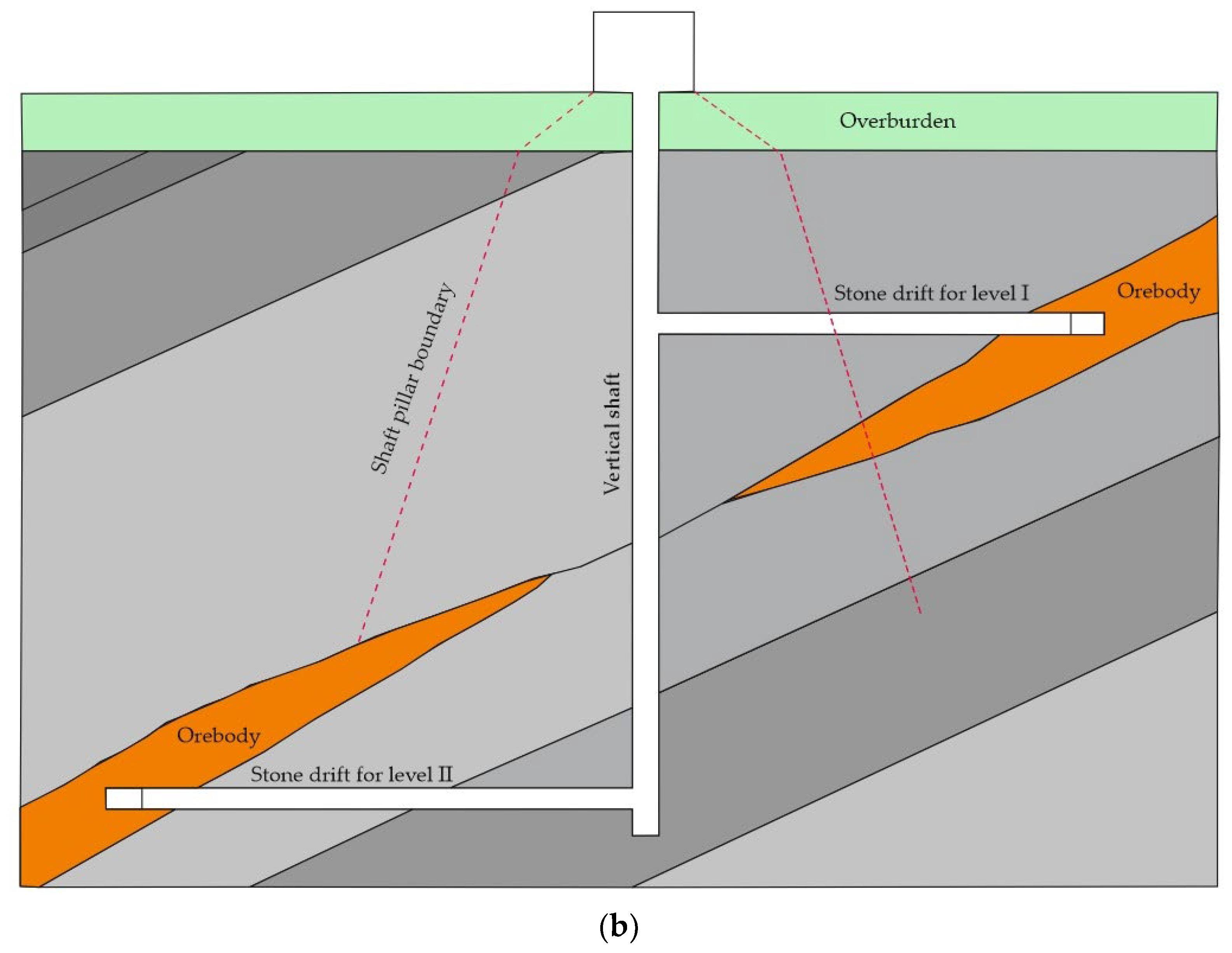
2.3. Access by Means of Inclined Shaft
- If the shaft is sinking in the deposit, the excavated material is obtained when the deposit is made available, and there is no need to drive stone drifts, which reduces the costs of stone works.
- In the case of driving a shaft in floor rocks, it avoids leaving a supporting pillar along the shaft, and the length of the stone drifts is shorter than in the case of a vertical shaft.
- Faster preparation of the deposit for exploitation.
- The need to leave support pillars along the shaft, which are usually larger than the protective pillars at vertical shafts. If the deposit consists of several seams or veins, and the inclined shaft is sunk in one of the upper seams, it is necessary to leave a protective pillar in the lower seams (or veins), which significantly increases the loss of useful mineral.
- When sinking a shaft in a deposit with a variable inclination, either take back rock or change the direction of the shaft according to the inclination of the deposit. The transport of the output in a shaft with a variable inclination encounters considerable difficulties and reduces its extraction capacity.
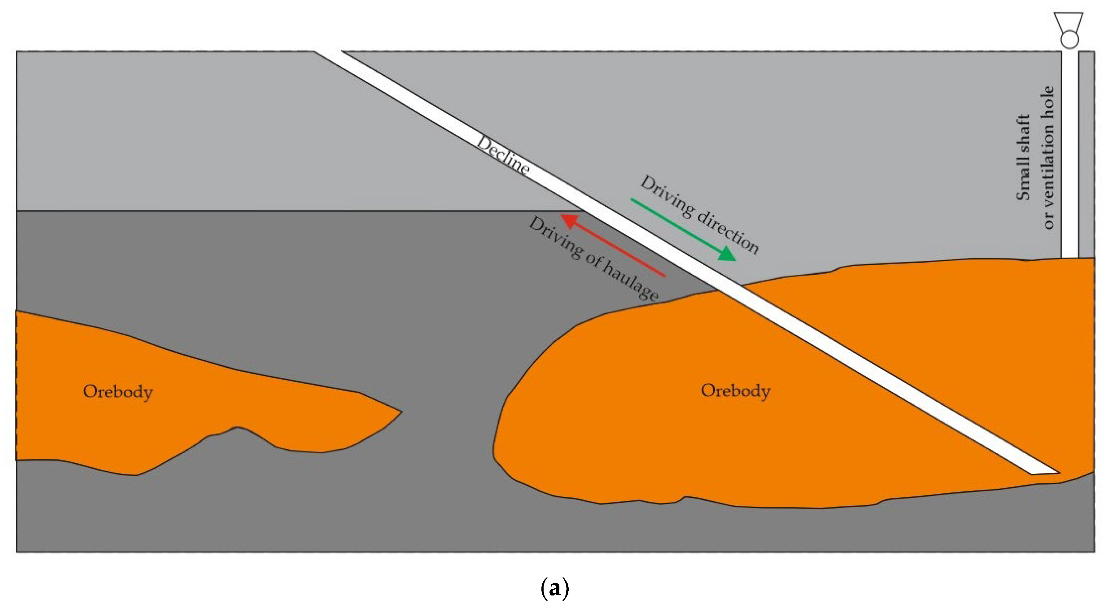
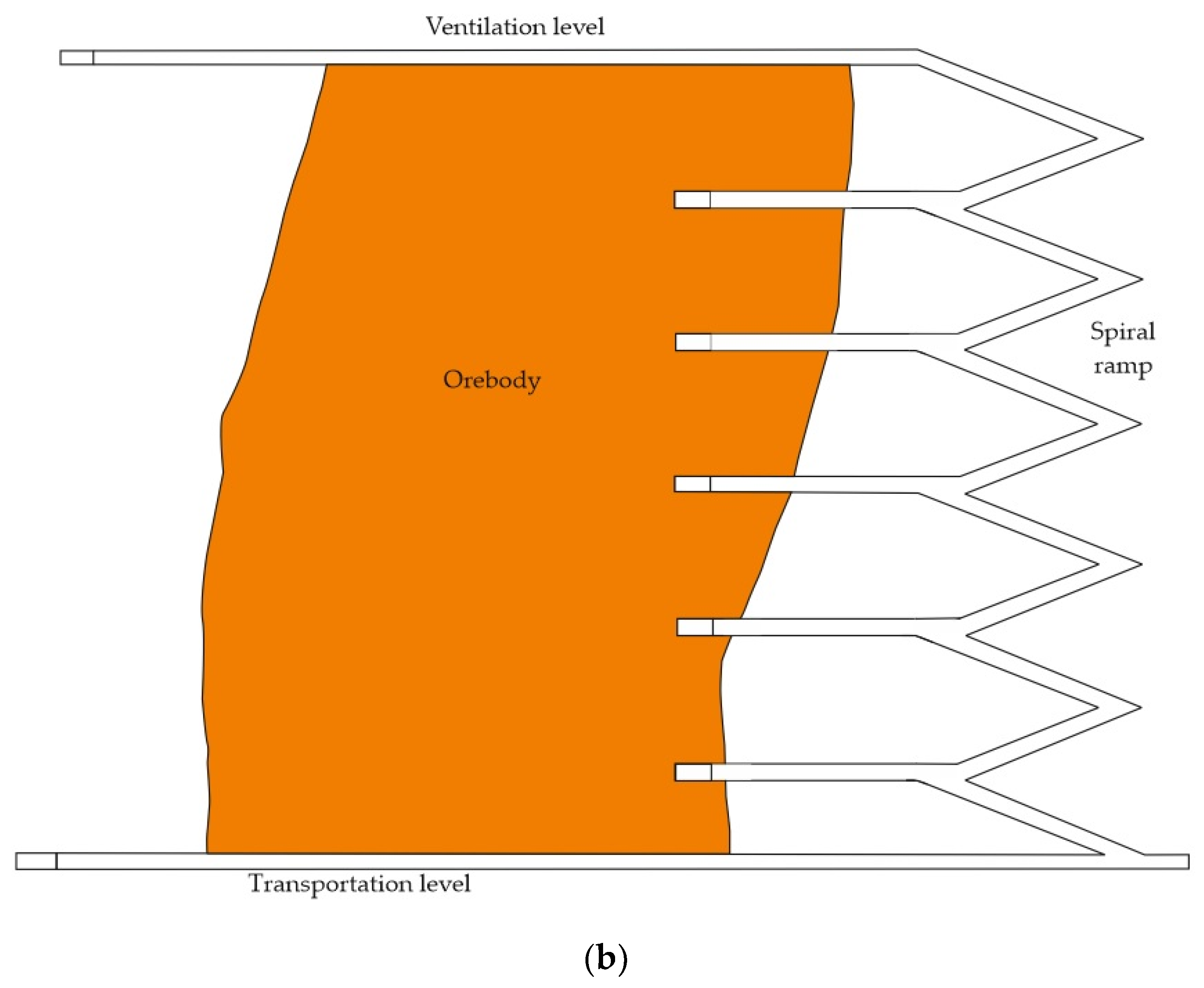
2.4. Access by Means of Decline
- The possibility of driving the excavation with the use of full-section machines (TBM) [28];
- Direct inspection of the excavation and equipment during the opening and operational works (for the vertical shaft, time should be allocated for its inspection);
- Easier movement of the mining crew between the levels (without the use of a hoisting machine);
- In the case of using a belt conveyor in a decline, high efficiency can be obtained (for a conveyor with a belt width of 1400 mm, up to 38.000 t/day can be obtained) [29].
- The length of the decline providing access to a specific level and is several times greater than that of a vertical shaft;
- More resources are trapped in the decline protection pillar;
- In the case of transporting people and materials by suspended monorails installed in the decline, their efficiency is much lower compared with vertical transport in the shaft;
- Because the materials of the conveyor belt are flame retardant, it means that they can only be installed in the exhaust air stream. In addition, the greater length of the decline and, as a rule, a smaller cross-section in relation to the shafts, means several times greater ventilation resistance. Since the relative speed of the flowing air and the moving belt should be a maximum of 5 m/s, which allows to avoid excessive dust lifting, it means that the transporting decline cannot be used as the main ventilation excavation at the same time [30].
3. Relationship the Various Stages of Mining Works
- to—time advance indicator;
- te—horizontal exploitation time, (days);
- ta+d—time to access and prepare the level, (days).
- P—annual mining capacity of the shaft, (tons);
- α—the angle of the deck, (°);
- ρ—output dilution coefficient;
- n—number of operating wings (parts);
- L—annual progress of exploitation works along strike, (m);
- m—deck thickness, (m);
- γ—volume weight of the output, (t/m3);
- η—deposit utilization factor.
- V—volume of workings around shaft, (m3);
- Ko—cost of making 1 m3 of a rock excavation;
- Lk—length of the preparatory excavation of the level, (m);
- Kk—unit cost of 1 m of the drift;
- S—horizontal projection of the deposit, (m2);
- e—haulage cost of 1 ton of excavated material;
- b—cost of dewatering per 1 ton of extraction;
- Δ—increase in operating costs per 1 ton of excavated material (output) with an increase in the height of the level by 1 m.
- w—advance factor according to Equation (10):
- to—time of exploitation;
- t—time for access and preparatory the lower mining level.
4. Conclusions
Author Contributions
Funding
Data Availability Statement
Conflicts of Interest
References
- Leng, D.; Shao, S.; Xie, Y.; Wang, H.; Liu, G. A brief review of recent progress on deep sea mining vehicle. Ocean Eng. 2021, 228, 108565. [Google Scholar] [CrossRef]
- Winterstetter, A.; Heuss-Assbichler, S.; Stegemann, J.; Kral, U.; Wäger, P.; Osmani, M.; Rechberger, H. The role of anthropogenic resource classification in supporting the transition to a circular economy. J. Clean. Prod. 2021, 297, 126753. [Google Scholar] [CrossRef]
- Pietrzyk, S.; Tora, B. Processing of Non-Ferrous Metals Secondary Raw Materials in Poland–Trends, Opportunities and Threats. J. Pol. Miner. Eng. Soc. 2017, 18, 81–92. [Google Scholar] [CrossRef]
- Tejaswini, M.S.S.R.; Pathak, P.; Gupta, D.K. Sustainable approach for valorization of solid wastes as a secondary resource through urban mining. J. Environ. Manag. 2022, 319, 115727. [Google Scholar] [CrossRef] [PubMed]
- Xu, F.; Su, J. Towards a legal regime of benefits sharing for space mining: With some experience from the Area. Resour. Policy 2022, 76, 102627. [Google Scholar] [CrossRef]
- Flores, G.; Catalan, A. A transition from a large open pit into a novel “macroblock variant” block caving geometry at Chuquicamata mine, Codelco Chile. J. Rock Mech. Geotech. Eng. 2019, 11, 549–561. [Google Scholar] [CrossRef]
- Ross, I.T.; Stewart, C.A. Issues with transitioning from open pits to underground caving mines. In MassMin 2020: Proceedings of the Eighth International Conference and Exhibition on Mass Mining, Virtual, 4–8 October 2020; Castro, R., Báez, F., Suzuki, K., Eds.; University of Chile: Santiago, Chile, 2020; pp. 221–238. [Google Scholar] [CrossRef]
- Skrzypkowski, K. Determination of the Backfilling Time for the Zinc and Lead Ore Deposits with Application of the BackfillCAD Model. Energies 2021, 14, 3186. [Google Scholar] [CrossRef]
- Hou, J.; Li, G.; Hu, N. Optimization of underground mine access layout and production scheduling. Miner. Resour. Manag. 2020, 26, 87–108. [Google Scholar]
- Musingwini, C. Optimization in underground mineplanning-developments and opportunities. J. S. Afr. Inst. Min. Metall. 2016, 116, 809–820. [Google Scholar] [CrossRef]
- Bołoz, Ł.; Biały, W. Automation and Robotization of Underground Mining in Poland. Appl. Sci. 2020, 10, 7221. [Google Scholar] [CrossRef]
- Afum, B.O.; Ben-Awuah, E. A Review of Models and Algorithms for Surface-Underground Mining Options and Transitions Optimization: Some Lessons Learnt and the Way Forward. Mining 2021, 1, 112–134. [Google Scholar] [CrossRef]
- Sirinanda, K.; Brazil, M.; Grossman, P.; Rubinstein, H.; Thomas, D. Optimally locating a junction point for an underground mine to maximise the net present value. ANZIAM J. 2014, 55, 315–328. [Google Scholar] [CrossRef]
- Takuski, S. The Technique of Underground Mining of ore Deposits; University script no. 769; AGH University of Science and Technology Publishing House: Kraków, Poland, 1980; p. 92. (In Polish) [Google Scholar]
- Skrzypkowski, K.; Korzeniowski, W.; Zagórski, K.; Zagórska, A. Adjustment of the Yielding System of Mechanical Rock Bolts for Room and Pillar Mining Method in Stratified Rock Mass. Energies 2020, 13, 2082. [Google Scholar] [CrossRef]
- Nie, X.; Wei, X.; Li, X.; Lu, C. Heat Treatment and Ventilation Optimization in a Deep Mine. Adv. Civ. Eng. 2018, 2018, 1529490. [Google Scholar] [CrossRef]
- Yardimci, A.; Karpuz, C. Shortest path optimization of haul road design in underground mines using an evolutionary algorithm. Appl. Soft Comput. 2019, 83, 105668. [Google Scholar] [CrossRef]
- Zeqiri, K.; Ibishi, G.; Shabani, M.; Kortnik, K.; Bilir, M.E.; Geniş, M.; Yavuz, M.; Hetemi, M.; Bacak, G. Preliminary support design for underground mine adit, Artana mine, Kosovo. Min. Sci. 2021, 28, 141–159. [Google Scholar] [CrossRef]
- Galdón, J.M.; Rey, J.; Martínez, J.; Hidalgo, M.C. Application of geophysical prospecting techniques to evaluate geological-mining heritage: The Sinapismo mine (La Carolina, Southern Spain). Eng. Geol. 2017, 218, 152–161. [Google Scholar] [CrossRef]
- Bakhtavar, E.; Yousefi, S.; Jafarpour, A. Evaluation of shaft locations in underground mines: Fuzzy multi-objective optimization by ratio analysis with fuzzy cognitive map weights. J. S. Afr. Inst. Min. Metall. 2019, 119, 855–864. [Google Scholar] [CrossRef]
- Costa, L.; Silva, J.; Lima, H. Analysis of options of production and access ways in underground mines. Min. REM Int. Eng. J. 2018, 70, 237–242. [Google Scholar] [CrossRef]
- Wu, F.; Qin, Y.; Xu, H.; Zhang, F.; Chu, X. Numerical Simulation of Deformation and Failure Mechanism of Main Inclined Shaft in Yuxi Coal Mine, China. Appl. Sci. 2022, 12, 5531. [Google Scholar] [CrossRef]
- Yu, W.; Wang, W.; Wu, G.; Yu, X.; Peng, W. Three Zones and Support Technique for Large Section Incline Shaft Crossing Goaf. Geotech. Geol. Eng. 2017, 35, 1921–1931. [Google Scholar] [CrossRef]
- Krishna, P. Analysis on the Dynamics of Burst Debris Flood at the Inclined Pressure-Shaft of Svandalsflona Hydropower Project, Norway. Rock Mech. Rock Eng. 2014, 47, 923–932. [Google Scholar]
- Haviland, D.; Marshall, J. Fundamental behaviours of production traffic in underground mine haulage ramps. Int. J. Min. Sci. Technol. 2015, 25, 7–14. [Google Scholar] [CrossRef]
- Rupprecht, S.M. Mine development–access to deposit. J. S. Afr. Inst. Min. Metall. 2012, 2012, 101–120. [Google Scholar]
- Wilson, R.B.; Willis, R.P.H.; Du Plessis, A.G. Considerations in the choice of primary access and transportation options in platinum mines. In International Platinum Conference: Platinum Adding Value; The South African Institute of Mining and Metallurgy: Johannesburg, South Africa, 2004; pp. 269–274. [Google Scholar]
- Zheng, Y.L.; Zhang, Q.B.; Zhao, J. Challenges and opportunities of using tunnel boring machines in mining. Tunn. Undergr. Space Technol. 2016, 57, 287–299. [Google Scholar] [CrossRef]
- Czaja, P.; Kamiński, P. The possibility of access to copper ore deposits on Fore-Sudetic Monocline with a inclined shaft. Cuprum 2015, 3, 19–35. [Google Scholar]
- Jakubowski, M. A comparison of technical-economical aspects of primary access to the orebody via the vertical shaft and the decline. Cuprum 2014, 4, 73–92. [Google Scholar]
- Takuski, S.; Maciejasz, Z.; Gajoch, K.; Piechota, S.; Wziętek, B. Mining; University script no. 723; AGH University of Science and Technology Publishing House: Kraków, Poland, 1980; p. 64. (In Polish) [Google Scholar]
- Wagner, H. Deep Mining: A Rock Engineering Challenge. Rock Mech. Rock Eng. 2019, 52, 1417–1446. [Google Scholar] [CrossRef]
- Zhu, S.; Wu, S.; Cheng, J.; Li, S.; Li, M. An Underground Air-Route Temperature Prediction Model for Ultra-Deep Coal Mines. Minerals 2015, 5, 527–545. [Google Scholar] [CrossRef]
- Dreger, M.; Kędzior, S. Methane emissions against the background of natural and mining conditions in the Budryk and Pniówek mines in the Upper Silesian Coal Basin (Poland). Environ. Earth Sci. 2021, 80, 746. [Google Scholar] [CrossRef]
- Wierzbicki, M.; Młynarczuk, M. Structural aspects of gas and dolomite outburst in Rudna copper mine, Poland. Int. J. Rock Mech. Min. Sci. 2013, 57, 113–118. [Google Scholar] [CrossRef]
- Wierzbicki, M.; Skoczylas, N. The outburst risk as a function of the methane capacity and firmness of a coal seam. Arch. Min. Sci. 2014, 59, 1023–1031. [Google Scholar] [CrossRef]


Publisher’s Note: MDPI stays neutral with regard to jurisdictional claims in published maps and institutional affiliations. |
© 2022 by the authors. Licensee MDPI, Basel, Switzerland. This article is an open access article distributed under the terms and conditions of the Creative Commons Attribution (CC BY) license (https://creativecommons.org/licenses/by/4.0/).
Share and Cite
Skrzypkowski, K.; Zagórski, K.; Zagórska, A.; Sengani, F. Access to Deposits as a Stage of Mining Works. Energies 2022, 15, 8740. https://doi.org/10.3390/en15228740
Skrzypkowski K, Zagórski K, Zagórska A, Sengani F. Access to Deposits as a Stage of Mining Works. Energies. 2022; 15(22):8740. https://doi.org/10.3390/en15228740
Chicago/Turabian StyleSkrzypkowski, Krzysztof, Krzysztof Zagórski, Anna Zagórska, and Fhatuwani Sengani. 2022. "Access to Deposits as a Stage of Mining Works" Energies 15, no. 22: 8740. https://doi.org/10.3390/en15228740
APA StyleSkrzypkowski, K., Zagórski, K., Zagórska, A., & Sengani, F. (2022). Access to Deposits as a Stage of Mining Works. Energies, 15(22), 8740. https://doi.org/10.3390/en15228740