
The Optimal Configuration of Wave Energy Conversions Respective to the Nearshore Wave Energy Potential

 ,
,  ,
, 
Abstract
:1. Introduction
Related Works
2. Wave Energy Resource and the WEC Mechanism
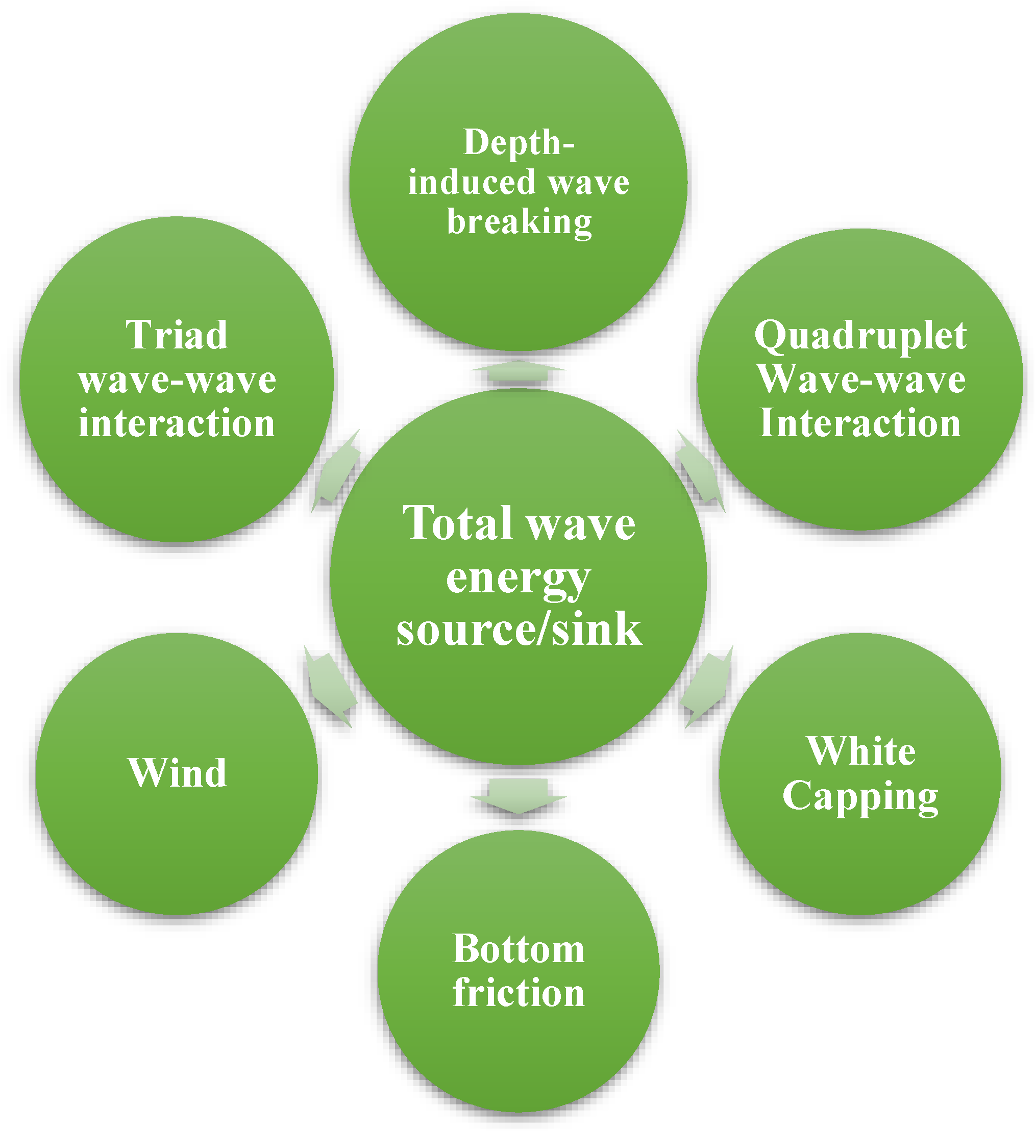
2.1. Wave Energy Characteristics
2.2. Wave Energy Converter Types
2.2.1. Point Absorbers
2.2.2. Oscillating Water Columns
2.2.3. Attenuators
2.2.4. Terminators
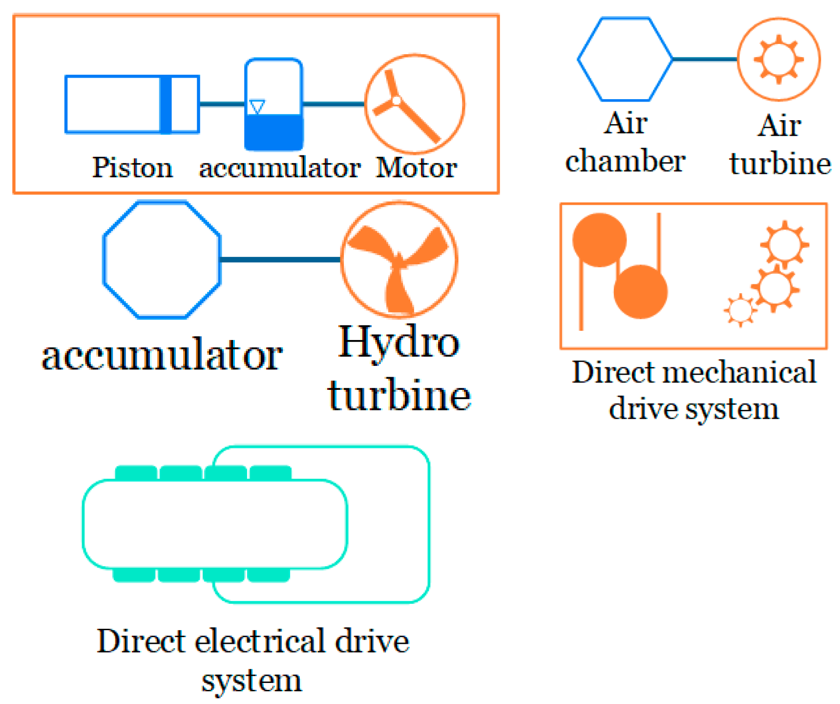
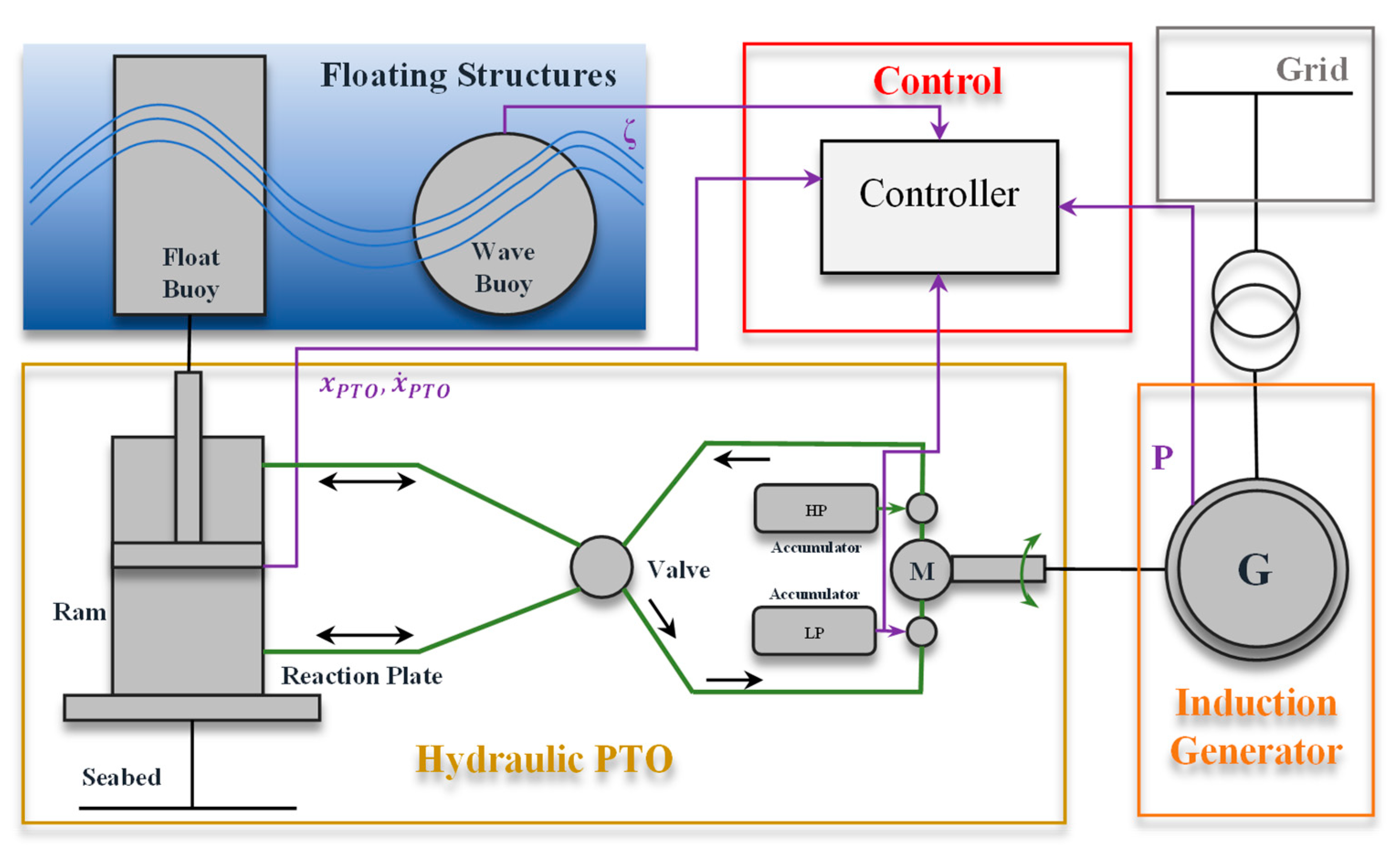
2.3. Power Take-Off Mechanism
2.4. Hydrodynamic Interaction Definition
3. Recent Advances in Optimizing the WEC Configuration
3.1. Optimization Approaches
3.1.1. Genetic Algorithm
3.1.2. Evolutionary Multi-and Many-Objective Algorithms
3.2. Layout-PTO-Geometry Optimization
4. Future Research Direction
5. Conclusions
- -
- Numerous relevant elements are used in the layout optimization studies to find the best solutions. In order to identify the most consistent, repeatable findings throughout the examined research, two patterns, namely the linear and the arrowhead patterns, are depicted in this study. The performance of the arrangement is directly affected by variables, such as the distance and wave direction. Therefore, we agree on a general statement of how increasing or decreasing these factors affects the arrangement of the array.
- -
- Recently, it has been established as a reasonable standpoint to use the optimization techniques to increase the control methods and enhance the PTO coefficients. The modern meta-heuristic algorithms have also optimized these coefficients. Recent research shows that the maximum power output at lower frequencies increases with the increasing damping coefficient. Experimental evidence is presented to support this notion. A complete cost-benefit analysis is required for each of the many PTO systems that are categorized in this paper, even if the PTO system setup will enhance the LCoE. Further study on the active control methods for the PTO system of the conversions is needed.
- -
- According to studies, the WECs’ shape optimization may significantly boost performance. Geometry optimization combined with the PTO control approach may lead to better outcomes. While increasing the WECs’ geometry will boost their profitability, performance should be adjusted in light of the rising prices.
Funding
Institutional Review Board Statement
Informed Consent Statement
Data Availability Statement
Conflicts of Interest
Nomenclature
| WEC | Wave energy converter |
| EA | Evolutionary algorithm |
| GA | Genetic algorithm |
| OWSC | Oscillating wave surge converter |
| BEM | Boundary element method |
| CMA-EA | Covariance matrix adaptation evolutionary algorithm |
| CMA-ES | Covariance matrix adaptation evolutionary strategy |
| MM | Metamodel algorithm |
| PTO | Power take-off |
| SWAN | Simulating WAve Nearshore |
| DOF | Degrees of freedom |
| PA | Point absorber |
| RAO | Response amplitude response |
| OWC | Oscillating water column |
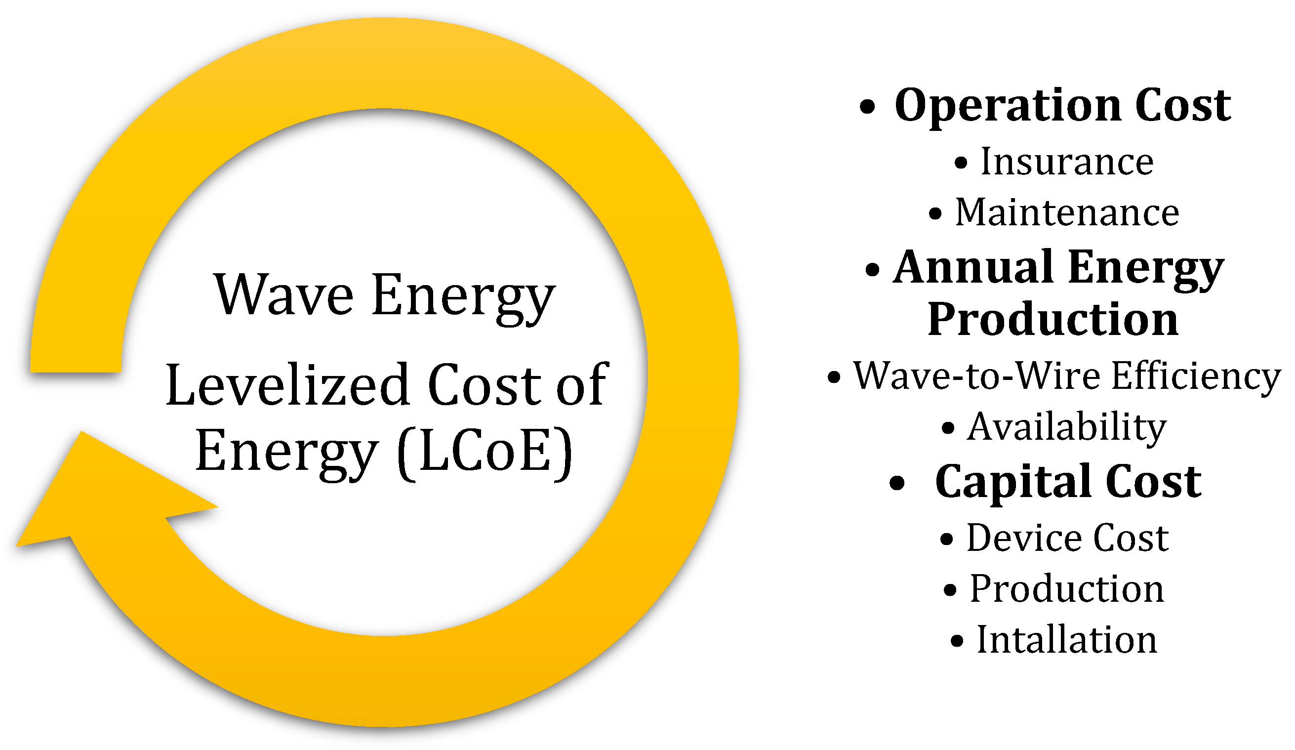
| LCoE | Levelized cost of energy |
| WD | Wave dragon |
| SSG | Sea slot-cone generator |
| PF | Potential flow |
| CFD | Computational fluid dynamics |
| DNS | Direct numerical simulation |
| LES | Large eddy simulation |
| RANS | Reynolds average Navier–Stokes |
| NSE | Navier–Stokes equation |
| GSO | Glowworm swarm optimization |
| NM | Nelder–Mead |
| ANN | Artificial neural network |
| SA | Simulating annealing |
| PI | Parabolic intersection |
| HGGA | Hidden genes genetic algorithm |
| RBFNN | Radial basis function neural network |
| COBYLA | Constrained optimization technique by linear approximation |
| MOEA | Many-objective evolutionary algorithm |
| NSGA | Non-dominated sorting genetic algorithm |
| HGA-PSO | Hybrid genetic algorithm-particle swarm optimization |
| HPTO | Hydraulic power take-off |
| FSPMLG | Flux-switching permanent magnet linear generator |
| DE | Differential equation |
| ANSO | Adaptive neuro-surrogate model |
| HCCA | Hybrid coordination channel access |
References
- Winter, N. Renewables 2022 Global Status Report United States of America Factsheet; Coherent Digital, LLC: Alexandria, VA, USA, 2022. [Google Scholar]
- Thorpe, T.W. A Brief Review of Wave Energy; Researchgate: Berlin, Germany, 1999. [Google Scholar]
- Callaghan, J.; Boud, R. Future Marine Energy. Results of the Marine Energy Challenge: Cost Competitiveness and Growth of Wave and Tidal Stream Energy; Carbon Trust: London, UK, 2006; Volume 40. [Google Scholar]
- Cornett, A.M. A global wave energy resource assessment. In Proceedings of the Eighteenth International Offshore and Polar Engineering Conference, Sapporo, Japan, 6 July 2008. [Google Scholar]
- Barstow, S.; Mørk, G.; Mollison, D.; Cruz, J. The wave energy resource. In Ocean Wave Energy; Springer: Berlin/Heidelberg, Germany, 2008; pp. 93–132. [Google Scholar]
- Mork, G.; Barstow, S.; Kabuth, A.; Pontes, M.T. Assessing the global wave energy potential. In Proceedings of the International Conference on Offshore Mechanics and Arctic Engineering, Waginengin, The Netherlands, 16–17 February 2010; Volume 49118, pp. 447–454. [Google Scholar]
- Barstow, S.; Mørk, G.; Lønseth, L.; Mathisen, J.P. WorldWaves wave energy resource assessments from the deep ocean to the coast. J. Energy Power Eng. 2011, 5, 730–742. [Google Scholar]
- Dashwood, J. 4. The outlook for energy: A view to 2040. In Australia’s Energy Options: Renewables and Efficiency; CEDA: Melbourne, Australia, 2012; p. 45. [Google Scholar]
- Arinaga, R.A.; Cheung, K.F. Atlas of global wave energy from 10 years of reanalysis and hindcast data. Renew. Energy 2012, 39, 49–64. [Google Scholar] [CrossRef]
- Falnes, J.; Kurniawan, A. Fundamental formulae for wave-energy conversion. R. Soc. Open Sci. 2015, 2, 140305. [Google Scholar] [CrossRef] [PubMed] [Green Version]
- Pérez-Collazo, C.; Greaves, D.; Iglesias, G. A review of combined wave and offshore wind energy. Renew. Sustain. Energy Rev. 2015, 42, 141–153. [Google Scholar] [CrossRef] [Green Version]
- Clément, A.; McCullen, P.; Falcão, A.; Fiorentino, A.; Gardner, F.; Hammarlund, K.; Lemonis, G.; Lewis, T.; Nielsen, K.; Petroncini, S.; et al. Wave energy in Europe: Current status and perspectives. Renew. Sustain. Energy Rev. 2002, 6, 405–431. [Google Scholar] [CrossRef]
- Folley, M.; Whittaker, T.J.T. Analysis of the nearshore wave energy resource. Renew. Energy 2009, 34, 1709–1715. [Google Scholar] [CrossRef]
- Alonso, R.; Solari, S.; Teixeira, L. Wave energy resource assessment in Uruguay. Energy 2015, 93, 683–696. [Google Scholar] [CrossRef]
- Besio, G.; Mentaschi, L.; Mazzino, A. Wave energy resource assessment in the Mediterranean Sea on the basis of a 35-year hindcast. Energy 2016, 94, 50–63. [Google Scholar] [CrossRef]
- Previsic, M. Offshore Wave Energy Conversion Devices; Electric Power Research Institute (EPRI) Report; Palo Alto: Santa Clara, CA, USA, 2004; pp. 26–130. [Google Scholar]
- Aderinto, T.; Li, H. Ocean wave energy converters: Status and challenges. Energies 2018, 11, 1250. [Google Scholar] [CrossRef] [Green Version]
- Iuppa, C.; Cavallaro, L.; Foti, E.; Vicinanza, D. Potential wave energy production by different wave energy converters around Sicily. J. Renew. Sustain. Energy 2015, 7, 61701. [Google Scholar] [CrossRef]
- Drew, B.; Plummer, A.R.; Sahinkaya, M.N. A Review of Wave Energy Converter Technology; Sage Publications Sage UK: London, UK, 2009. [Google Scholar]
- Polinder, H.; Scuotto, M. Wave energy converters and their impact on power systems. In Proceedings of the 2005 International Conference on Future Power Systems, Amsterdam, The Netherlands, 16–18 November 2005. [Google Scholar]
- Czech, B.; Bauer, P. Wave energy converter concepts: Design challenges and classification. IEEE Ind. Electron. Mag. 2012, 6, 4–16. [Google Scholar] [CrossRef]
- The Queen’s University of Belfast. Islay Limpet Wave Power Plant Report; Report No. JOR3-CT98-0312; Report for European Commission; Queens University: Kingston, ON, Canada, 2002. [Google Scholar]
- Zanopol, A.T.; Onea, F.; Rusu, E. Studies concerning the influence of the wave farms on the nearshore processes. Int. J. Geosci. 2014, 2014, 47121. [Google Scholar] [CrossRef] [Green Version]
- Boake, C.B.; Whittaker, T.J.T.; Folley, M.; Ellen, H. Overview and initial operational experience of the LIMPET wave energy plant. In Proceedings of the Twelfth International Offshore and Polar Engineering Conference, Kitakyushu, Japan, 26–31 May 2002. [Google Scholar]
- Rusu, E.; Onea, F. Estimation of the wave energy conversion efficiency in the Atlantic Ocean close to the European islands. Renew. Energy 2016, 85, 687–703. [Google Scholar] [CrossRef]
- Cockerill, T.T.; Kühn, M.; van Bussel, G.J.W.; Bierbooms, W.; Harrison, R. Combined technical and economic evaluation of the Northern European offshore wind resource. J. Wind. Eng. Ind. Aerodyn. 2001, 89, 689–711. [Google Scholar] [CrossRef]
- Leijon, M.; Danielsson, O.; Eriksson, M.; Thorburn, K.; Bernhoff, H.; Isberg, J.; Sundberg, J.; Ivanova, I.; Sjöstedt, E.; Ågren, O.J.R.E.; et al. An electrical approach to wave energy conversion. Renew. Energy 2006, 31, 1309–1319. [Google Scholar] [CrossRef]
- Jolly, C. The Ocean Economy in 2030. In Proceedings of the Workshop on Maritime Cluster and Global Challenges 50th Anniversary of the WP6, Paris, France, 1 December 2016; Volume 1. [Google Scholar]
- Pelc, R.; Fujita, R.M. Renewable energy from the ocean. Mar. Policy 2002, 26, 471–479. [Google Scholar] [CrossRef]
- Bedard, R.; Jacobson, P.T.; Previsic, M.; Musial, W.; Varley, R. An overview of ocean renewable energy technologies. Oceanography 2010, 23, 22–31. [Google Scholar] [CrossRef]
- Budal, K. Theory for absorption of wave power by a system of interacting bodies. J. Ship Res. 1977, 21, 248–254. [Google Scholar] [CrossRef]
- Thomas, G.P.; Evans, D.V. Arrays of three-dimensional wave-energy absorbers. J. Fluid Mech. 1981, 108, 67–88. [Google Scholar] [CrossRef]
- Falnes, J. Radiation impedance matrix and optimum power absorption for interacting oscillators in surface waves. Appl. Ocean Res. 1980, 2, 75–80. [Google Scholar] [CrossRef]
- Moarefdoost, M.M.; Snyder, L.V.; Alnajjab, B. Layouts for ocean wave energy farms: Models, properties, and optimization. Omega 2017, 66, 185–194. [Google Scholar] [CrossRef]
- Child, B.F.M.; Venugopal, V. Optimal configurations of wave energy device arrays. Ocean Eng. 2010, 37, 1402–1417. [Google Scholar] [CrossRef]
- Fitzgerald, C.; Thomas, G. A preliminary study on the optimal formation of an array of wave power devices. In Proceedings of the 7th European Wave and Tidal Energy Conference, Porto, Portugal, 11–13 September 2007; pp. 11–14. [Google Scholar]
- McGuinness, J.P.L.; Thomas, G. The constrained optimisation of small linear arrays of heaving point absorbers. Part I: The influence of spacing. Int. J. Mar. Energy 2017, 20, 33–44. [Google Scholar] [CrossRef]
- Tay, Z.Y.; Venugopal, V. Hydrodynamic interactions of oscillating wave surge converters in an array under random sea state. Ocean Eng. 2017, 145, 382–394. [Google Scholar] [CrossRef] [Green Version]
- Bozzi, S.; Giassi, M.; Miquel, A.M.; Antonini, A.; Bizzozero, F.; Gruosso, G.; Archetti, R.; Passoni, G. Wave energy farm design in real wave climates: The Italian offshore. Energy 2017, 122, 378–389. [Google Scholar] [CrossRef] [Green Version]
- Göteman, M.; Giassi, M.; Engström, J.; Isberg, J. Advances and Challenges in Wave Energy Park Optimization—A Review. Front. Energy Res. 2020, 8, 26. [Google Scholar] [CrossRef] [Green Version]
- Babarit, A. On the park effect in arrays of oscillating wave energy converters. Renew. Energy 2013, 58, 68–78. [Google Scholar] [CrossRef] [Green Version]
- Sarkar, D.; Contal, E.; Vayatis, N.; Dias, F. Prediction and optimization of wave energy converter arrays using a machine learning approach. Renew. Energy 2016, 97, 504–517. [Google Scholar] [CrossRef]
- Korde, U.A.; Ringwood, J. Hydrodynamic Control of Wave Energy Devices; Cambridge University Press: Cambridge, UK, 2016. [Google Scholar] [CrossRef]
- Göteman, M. Wave energy parks with point-absorbers of different dimensions. J. Fluids Struct. 2017, 74, 142–157. [Google Scholar] [CrossRef] [Green Version]
- Esmaeilzadeh, S.; Alam, M.R. Shape optimization of wave energy converters for broadband directional incident waves. Ocean Eng. 2019, 174, 186–200. [Google Scholar] [CrossRef]
- Bellew, S.; Stallard, T.; Stansby, P. Optimisation of a Heterogenous Array of Heaving Floats. In Proceedings of the 8th European Wave and Tidal Energy Conference (EWTEC), Uppsala, Sweden, 7–11 September 2009. [Google Scholar]
- Saulnier, J.; Ricci, P.; Pontes, M.; Falcao, A.d.O. Spectral Bandwidth and WEC Performance Assessment. In Proceedings of the 7th European Wave and Tidal Energy Conference (EWTEC 2007), Porto, Portugal, 11–13 September 2007. [Google Scholar]
- McNatt, J.C.; Özkan-Haller, H.T.; Morrow, M.; Delos-Reyes, M. Preliminary modeling and analysis of a horizontal pressure differential wave energy converter. J. Offshore Mech. Arct. Eng. 2014, 136, 011901. [Google Scholar] [CrossRef]
- Wolgamot, H.A.; Taylor, P.H.; Taylor, R.E. The interaction factor and directionality in wave energy arrays. Ocean Eng. 2012, 47, 65–73. [Google Scholar] [CrossRef]
- Babarit, A. Impact of long separating distances on the energy production of two interacting wave energy converters. Ocean Eng. 2010, 37, 718–729. [Google Scholar] [CrossRef] [Green Version]
- Borgarino, B.; Babarit, A.; Ferrant, P. Impact of wave interactions effects on energy absorption in large arrays of wave energy converters. Ocean Eng. 2012, 41, 79–88. [Google Scholar] [CrossRef] [Green Version]
- Weller, S.D.; Stallard, T.J.; Stansby, P.K. Experimental measurements of irregular wave interaction factors in closely spaced arrays. IET Renew. Power Gener. 2010, 4, 628–637. [Google Scholar] [CrossRef]
- Göteman, M.; Engström, J.; Eriksson, M.; Isberg, J. Optimizing wave energy parks with over 1000 interacting point-absorbers using an approximate analytical method. Int. J. Mar. Energy 2015, 10, 113–126. [Google Scholar] [CrossRef] [Green Version]
- Wu, J.; Shekh, S.; Sergiienko, N.Y.; Cazzolato, B.S.; Ding, B.; Neumann, F.; Wagner, M. Fast and effective optimisation of arrays of submerged wave energy converters. In Proceedings of the Genetic and Evolutionary Computation Conference 2016, Denver, CO, USA, 20–24 July 2016; pp. 1045–1052. [Google Scholar] [CrossRef]
- Ruiz, P.M.; Nava, V.; Topper, M.B.R.; Minguela, P.R.; Ferri, F.; Kofoed, J.P. Layout Optimisation of Wave Energy Converter Arrays. Energies 2017, 10, 1262. [Google Scholar] [CrossRef] [Green Version]
- Giassi, M.; Göteman, M. Layout design of wave energy parks by a genetic algorithm. Ocean Eng. 2018, 154, 252–261. [Google Scholar] [CrossRef]
- Clauss, G.F.; Birk, L. Hydrodynamic shape optimization of large offshore structures. Appl. Ocean Res. 1996, 18, 157–171. [Google Scholar] [CrossRef]
- Birk, L. Application of constrained multi-objective optimization to the design of offshore structure hulls. J. Offshore Mech. Arct. Eng. 2009, 131, 011301. [Google Scholar] [CrossRef]
- ElChahal, G.; Lafon, P.; Younes, R. Modelling And Optimizing Floating Breakwaters Using Density Distribution. In Proceedings of the Seventeenth International Offshore and Polar Engineering Conference, Lisbon, Portugal, 1–6 July 2007. [Google Scholar]
- Kramer, M.V.; Frigaard, P. Efficient Wave Energy Amplification With Wave Reflectors. In Proceedings of the Twelfth International Offshore and Polar Engineering Conference, Kitakyushu, Japan, 26–31 May 2002. [Google Scholar]
- Vantorre, M.; Banasiak, R.; Verhoeven, R. Modelling of hydraulic performance and wave energy extraction by a point absorber in heave. Appl. Ocean Res. 2004, 26, 61–72. [Google Scholar] [CrossRef]
- Alves, M.; Traylor, H.; Sarmento, A. Hydrodynamic Optimization of a Wave Energy Converter Using a Heave Motion Buoy. In Proceedings of the 7th European Wave and Tidal Energy Conference (EWTEC 2007), Porto, Portugal, 11–13 September 2007. [Google Scholar]
- Ruellan, M.; BenAhmed, H.; Multon, B.; Josset, C.; Babarit, A.; Clement, A. Design Methodology for a SEAREV Wave Energy Converter. IEEE Trans. Energy Convers. 2010, 25, 760–767. [Google Scholar] [CrossRef] [Green Version]
- Babarit, A.; Hals, J.; Muliawan, M.J.; Kurniawan, A.; Moan, T.; Krokstad, J. Numerical benchmarking study of a selection of wave energy converters. Renew. Energy 2012, 41, 44–63. [Google Scholar] [CrossRef]
- McCabe, A.P. Constrained optimization of the shape of a wave energy collector by genetic algorithm. Renew. Energy 2013, 51, 274–284. [Google Scholar] [CrossRef]
- Kurniawan, A.; Moan, T. Multi-objective optimization of wave energy absorber geometry. In Modelling and Geometry Optimisation of Wave Energy Converters; Academia.edu: San Francisco, CA, USA, 2013. [Google Scholar]
- Kurniawan, A.; Moan, T. Optimal Geometries for Wave Absorbers Oscillating About a Fixed Axis. IEEE J. Ocean. Eng. 2013, 38, 117–130. [Google Scholar] [CrossRef]
- Glendenning, I. Ocean wave power. Appl. Energy 1977, 3, 197–222. [Google Scholar] [CrossRef]
- Neill, S.P.; Hashemi, M.R. Wave power variability over the northwest European shelf seas. Appl. Energy 2013, 106, 31–46. [Google Scholar] [CrossRef]
- Rusu, E.; Soares, C.G. Wave energy pattern around the Madeira Islands. Energy 2012, 45, 771–785. [Google Scholar] [CrossRef]
- Rusu, L.; Soares, C.G. Wave energy assessments in the Azores islands. Renew. Energy 2012, 45, 183–196. [Google Scholar] [CrossRef]
- Beyene, A.; Wilson, J.H. Digital mapping of California wave energy resource. Int. J. Energy Res. 2007, 31, 1156–1168. [Google Scholar] [CrossRef]
- Henfridsson, U.; Neimane, V.; Strand, K.; Kapper, R.; Bernhoff, H.; Danielsson, O.; Leijon, M.; Sundberg, J.; Thorburn, K.; Ericsson, E.; et al. Wave energy potential in the Baltic Sea and the Danish part of the North Sea, with reflections on the Skagerrak. Renew. Energy 2007, 32, 2069–2084. [Google Scholar] [CrossRef]
- López, I.; Iglesias, G. Efficiency of OWC wave energy converters: A virtual laboratory. Appl. Ocean Res. 2014, 44, 63–70. [Google Scholar] [CrossRef]
- Vicinanza, D.; Contestabile, P.; Ferrante, V. Wave energy potential in the north-west of Sardinia (Italy). Renew. Energy 2013, 50, 506–521. [Google Scholar] [CrossRef]
- Pinson, P.; Reikard, G.; Bidlot, J.R. Probabilistic forecasting of the wave energy flux. Appl. Energy 2012, 93, 364–370. [Google Scholar] [CrossRef] [Green Version]
- Li, Y.; Willman, L. Feasibility analysis of offshore renewables penetrating local energy systems in remote oceanic areas—A case study of emissions from an electricity system with tidal power in Southern Alaska. Appl. Energy 2014, 117, 42–53. [Google Scholar] [CrossRef]
- Delft3D-Wave User Manual; Delft University of Technology: Delft, The Netherlands, 2005.
- Roelvink, D.; Reniers, A.J.H.M.; Van Dongeren, A.; Van Thiel de Vries, J.; Lescinski, J.; McCall, R. XBeach Model Description and Manual; Unesco-IHE Institute for Water Education, Deltares and Delft University of Tecnhology: Delft, The Netherlands, 2010. [Google Scholar]
- User Manual and System Documentation of WAVEWATCH III TM, Version 3.14. 2000. Available online: https://polar.ncep.noaa.gov/ (accessed on 13 December 2018).
- Booij, N.; Ris, R.C.; Holthuijsen, L.H. A third-generation wave model for coastal regions: 1. Model description and validation. J. Geophys. Res. Ocean. 1999, 104, 7649–7666. [Google Scholar]
- Ris, R.C.; Holthuijsen, L.H.; Booij, N. A third-generation wave model for coastal regions: 2. Verification. J. Geophys. Res. Ocean. 1999, 104, 7667–7681. [Google Scholar] [CrossRef]
- Team, S. SWAN, Scientific and Technical Documentation, SWAN Cycle III Version 40.72 ABC; Delft University of Technology: Delft, The Netherlands, 2009; Available online: http//www.swan.tudelft.nl (accessed on 1 March 2009).
- Salter, S.H. Wave power. Nature 1974, 249, 720–724. [Google Scholar] [CrossRef]
- López, I.; Andreu, J.; Ceballos, S.; de Alegría, I.M.; Kortabarria, I. Review of wave energy technologies and the necessary power-equipment. Renew. Sustain. Energy Rev. 2013, 27, 413–434. [Google Scholar] [CrossRef]
- Guo, B.; Ringwood, J.V. Geometric optimisation of wave energy conversion devices: A survey. Appl. Energy 2021, 297, 117100. [Google Scholar] [CrossRef]
- Falcão, A.F.O.; Henriques, J.C.C. Oscillating-water-column wave energy converters and air turbines: A review. Renew. Energy 2016, 85, 1391–1424. [Google Scholar] [CrossRef]
- He, F.; Zhang, H.; Zhao, J.; Zheng, S.; Iglesias, G. Hydrodynamic performance of a pile-supported OWC breakwater: An analytical study. Appl. Ocean Res. 2019, 88, 326–340. [Google Scholar] [CrossRef]
- Zheng, S.; Zhang, Y.; Iglesias, G. Coast/breakwater-integrated OWC: A theoretical model. Mar. Struct. 2019, 66, 121–135. [Google Scholar] [CrossRef]
- Yemm, R.; Pizer, D.; Retzler, C.; Henderson, R. Pelamis: Experience from concept to connection. Philos. Trans. R. Soc. A Math. Phys. Eng. Sci. 2012, 370, 365–380. [Google Scholar] [CrossRef] [Green Version]
- Allen, J.; Sampanis, K.; Wan, J.; Greaves, D.; Miles, J.; Iglesias, G. Laboratory Tests in the Development of WaveCat. Sustainability 2016, 8, 1339. [Google Scholar] [CrossRef] [Green Version]
- Oliveira, P.; Taveira-Pinto, F.; Morais, T.; Rosa-Santos, P. Experimental evaluation of the effect of wave focusing walls on the performance of the Sea-wave Slot-cone Generator. Energy Convers. Manag. 2016, 110, 165–175. [Google Scholar] [CrossRef]
- Vicinanza, D.; Margheritini, L.; Kofoed, J.P.; Buccino, M. The SSG Wave Energy Converter: Performance, Status and Recent Developments. Energies 2012, 5, 193–226. [Google Scholar] [CrossRef] [Green Version]
- Ricci, P.; Alves, M.; Falcao, A.; Sarmento, A. Optimisation of the geometry of wave energy converters. In Proceedings of the OTTI International Conference on Ocean Energy, Bremerhaven, Germany, 23–24 October 2006. [Google Scholar]
- Perugini, D. Numerical Models. In Advances in Volcanology; Springer: Berlin/Heidelberg, Germany, 2021; pp. 41–57. [Google Scholar] [CrossRef]
- Arzel, T.; Bjarte-Larsson, T.; Falnes, J. Hydrodynamic Parameters for a Floating WEC Force-Reacting against a Submerged Body [Wave Energy Converter]; OSTI.GOV: Oak Ridge, TN, USA, 2001. [Google Scholar]
- Pecher, A.; Kofoed, J.P. (Eds.) Handbook of Ocean Wave Energy; Springer: Berlin/Heidelberg, Germany, 2017; Volume 7. [Google Scholar] [CrossRef] [Green Version]
- Kagemoto, H.; Yue, D.K.P. Interactions among Multiple Three-Dimensional Bodies in Water Waves: An Exact Algebraic Method. J. Fluid Mech. 1986, 166, 189–209. [Google Scholar] [CrossRef]
- Mavrakos, S.A.; Koumoutsakos, P. Hydrodynamic interaction among vertical axisymmetric bodies restrained in waves. Appl. Ocean Res. 1987, 9, 128–140. [Google Scholar] [CrossRef]
- McNatt, J.C.; Venugopal, V.; Forehand, D. A novel method for deriving the diffraction transfer matrix and its application to multi-body interactions in water waves. Ocean Eng. 2015, 94, 173–185. [Google Scholar] [CrossRef] [Green Version]
- Nataliia Sergiienko. Wave Energy Converter (WEC) Array Simulator, MATLAB Central File Exchange. Available online: https://www.mathworks.com/matlabcentral/fileexchange/71840-wave-energy-converter-wec-array-simulator (accessed on 11 October 2022).
- Penalba, M.; Ringwood, J.V. Systematic complexity reduction of wave-to-wire models for wave energy system design. Ocean Eng. 2020, 217, 107651. [Google Scholar] [CrossRef]
- Sun, L.; Stansby, P.; Zang, J.; Moreno, E.C.; Taylor, P.H. Linear diffraction analysis for optimisation of the three-float multi-mode wave energy converter M4 in regular waves including small arrays. J. Ocean Eng. Mar. Energy 2016, 2, 429–438. [Google Scholar] [CrossRef] [Green Version]
- Sörensen, K. Metaheuristics—The metaphor exposed. Int. Trans. Oper. Res. 2013, 22, 3–18. [Google Scholar] [CrossRef]
- Beiranvand, V.; Hare, W.; Lucet, Y. Best practices for comparing optimization algorithms. Optim. Eng. 2017, 18, 815–848. [Google Scholar] [CrossRef] [Green Version]
- Noad, I.F.; Porter, R. Optimisation of arrays of flap-type oscillating wave surge converters. Appl. Ocean Res. 2015, 50, 237–253. [Google Scholar] [CrossRef]
- Vatchavayi, S.R. Heuristic Optimization of Wave Energy Converter Arrays. Retrieved from the University of Minnesota Digital Conservancy. 2019. Available online: https://hdl.handle.net/11299/206185 (accessed on 15 June 2019).
- Thomas, S.; Eriksson, M.; Göteman, M.; Hann, M.; Isberg, J.; Engström, J. Experimental and Numerical Collaborative Latching Control of Wave Energy Converter Arrays. Energies 2018, 11, 3036. [Google Scholar] [CrossRef] [Green Version]
- Feng, Z.; Kerrigan, E.C. LatchingDeclutching Control of Wave Energy Converters Using Derivative-Free Optimization. IEEE Trans. Sustain. Energy 2015, 6, 773–780. [Google Scholar] [CrossRef] [Green Version]
- Lyu, J.; Abdelkhalik, O.; Gauchia, L. Optimization of dimensions and layout of an array of wave energy converters. Ocean Eng. 2019, 192, 106543. [Google Scholar]
- Abdelkhalik, O.; Darani, S. Optimization of nonlinear wave energy converters. Ocean Eng. 2018, 162, 187–195. [Google Scholar]
- Giassi, M.; Göteman, M.; Thomas, S.; Engström, J.; Eriksson, M.; Isberg, J. Multi-parameter optimization of hybrid arrays of point absorber wave energy converters. In Proceedings of the 12th European Wave and Tidal Energy Conference (EWTEC), Cork, Ireland, 27–31 August 2017. [Google Scholar]
- Sharp, C.; DuPont, B. Wave energy converter array optimization: A genetic algorithm approach and minimum separation distance study. Ocean Eng. 2018, 163, 148–156. [Google Scholar] [CrossRef]
- Liu, Z.; Wang, Y.; Hua, X. Prediction and optimization of oscillating wave surge converter using machine learning techniques. Energy Convers. Manag. 2020, 210, 112677. [Google Scholar] [CrossRef]
- Powell, M.J.D. A direct search optimization method that models the objective and constraint functions by linear interpolation. In Advances in Optimization and Numerical Analysis; Springer: Dordrecht, The Netherlands, 1994; pp. 51–67. [Google Scholar]
- Abbass, H.A.; Sarker, R.; Newton, C. PDE: A Pareto-frontier differential evolution approach for multi-objective optimization problems. In Proceedings of the 2001 congress on evolutionary computation (IEEE Cat. No. 01TH8546), Seoul, Korea, 27–30 May 2001; Volume 2, pp. 971–978. [Google Scholar]
- Deb, K.; Pratap, A.; Agarwal, S.; Meyarivan, T. A fast and elitist multiobjective genetic algorithm: NSGA-II. IEEE Trans. Evol. Comput. 2002, 6, 182–197. [Google Scholar] [CrossRef] [Green Version]
- Srinivas, N.; Deb, K. Muiltiobjective optimization using nondominated sorting in genetic algorithms. Evol. Comput. 1994, 2, 221–248. [Google Scholar] [CrossRef]
- Deb, K.; Jain, H. An evolutionary many-objective optimization algorithm using reference-point-based nondominated sorting approach, part I: Solving problems with box constraints. IEEE Trans. Evol. Comput. 2013, 18, 577–601. [Google Scholar] [CrossRef]
- Capillo, A.; Luzi, M.; Pasc, M.; Rizzi, A.; Mascioli, F.M.F. Energy transduction optimization of a wave energy converter by evolutionary algorithms. In Proceedings of the 2018 International Joint Conference on Neural Networks (IJCNN), Rio de Janeiro, Brazil, 8–13 July 2018; pp. 1–8. [Google Scholar]
- Faraggiana, E.; Masters, I.; Chapman, J. Design of an optimization scheme for the WaveSub array. In Advances in Renewable Energies Offshore, Proceedings of the 3rd International Conference on Renewable Energies Offshore (RENEW), Lisbon, Portugal, 8–10 October 2018; Researchgate: Berlin, Germany, 2018; pp. 8–10. [Google Scholar]
- Garcia-Teruel, A.; DuPont, B.; Forehand, D.I.M. Hull geometry optimisation of wave energy converters: On the choice of the optimisation algorithm and the geometry definition. Appl. Energy 2020, 280, 115952. [Google Scholar] [CrossRef]
- Talaat, M.; Sedhom, B.E.; Hatata, A.Y. A new approach for integrating wave energy to the grid by an efficient control system for maximum power based on different optimization techniques. Int. J. Electr. Power Energy Syst. 2021, 128, 106800. [Google Scholar] [CrossRef]
- Mahdy, A.; Hasanien, H.M.; Hameed, W.H.A.; Turky, R.A.; Aleem, S.H.E.A.; Ebrahim, E.A. Nonlinear Modeling and Real-Time Simulation of a Grid-Connected AWS Wave Energy Conversion System. IEEE Trans. Sustain. Energy 2022, 13, 1744–1755. [Google Scholar] [CrossRef]
- Neshat, M.; Sergiienko, N.Y.; Mirjalili, S.; Nezhad, M.M.; Piras, G.; Garcia, D.A. Multi-mode wave energy converter design optimisation using an improved moth flame optimisation algorithm. Energies 2021, 14, 3737. [Google Scholar] [CrossRef]
- Neshat, M.; Mirjalili, S.; Sergiienko, N.Y.; Esmaeilzadeh, S.; Amini, E.; Heydari, A.; Garcia, D.A. Layout optimisation of offshore wave energy converters using a novel multi-swarm cooperative algorithm with backtracking strategy: A case study from coasts of Australia. Energy 2022, 239, 122463. [Google Scholar] [CrossRef]
- Huang, X.; Zhu, L.; Wu, W.; Lu, K.; Wang, K.; Koh, C.S. A Global Maximum Power Point Tracking Control Strategy Based on Particle Swarm Optimization Algorithm for Point-Absorber-Type Wave Energy Converters. In Proceedings of the 2021 IEEE 12th Energy Conversion Congress & Exposition-Asia (ECCE-Asia), Singapore, 24 May 2021; pp. 2089–2094. [Google Scholar] [CrossRef]
- de Andrés, A.D.; Guanche, R.; Meneses, L.; Vidal, C.; Losada, I.J. Factors that influence array layout on wave energy farms. Ocean Eng. 2014, 82, 32–41. [Google Scholar] [CrossRef]
- Balitsky, P.; Bacelli, G.; Ringwood, J.V. Control-influenced layout optimization of arrays of wave energy converters. In Proceedings of the International Conference on Offshore Mechanics and Arctic Engineering, San Francisco, CA, USA, 8–13 June 2014; Volume 45547, p. V09BT09A022. [Google Scholar]
- Blanco, M.; Moreno-Torres, P.; Lafoz, M.; Ramírez, D. Design parameter analysis of point absorber WEC via an evolutionary-algorithm-based dimensioning tool. Energies 2015, 8, 11203–11233. [Google Scholar] [CrossRef] [Green Version]
- Sharp, C.; DuPont, B. A multi-objective real-coded genetic algorithm method for wave energy converter array optimization. In Proceedings of the International Conference on Offshore Mechanics and Arctic Engineering, Busan, Korea, 19–24 June 2016; Volume 49972, p. V006T09A027. [Google Scholar]
- Ferri, F. Computationally efficient optimisation algorithms for WECs arrays. In Proceedings of the 12th European Wave and Tidal Energy Conference, Cork, Ireland, 27 August–1 September 2017; p. 798. [Google Scholar]
- Fang, H.-W.; Feng, Y.-Z.; Li, G.-P. Optimization of wave energy converter arrays by an improved differential evolution algorithm. Energies 2018, 11, 3522. [Google Scholar] [CrossRef] [Green Version]
- Neshat, M.; Alexander, B.; Wagner, M.; Xia, Y. A detailed comparison of meta-heuristic methods for optimising wave energy converter placements. In Proceedings of the Genetic and Evolutionary Computation Conference, Kyoto, Japan, 15–19 July 2018; pp. 1318–1325. [Google Scholar]
- Neshat, M.; Abbasnejad, E.; Shi, Q.; Alexander, B.; Wagner, M. Adaptive neuro-surrogate-based optimisation method for wave energy converters placement optimisation. In Proceedings of the International Conference on Neural Information Processing, Vancouver, BC, Canada, 8–14 December 2019; pp. 353–366. [Google Scholar]
- Neshat, M.; Sergiienko, N.Y.; Amini, E.; Majidi Nezhad, M.; Astiaso Garcia, D.; Alexander, B.; Wagner, M. A New Bi-Level Optimisation Framework for Optimising a Multi-Mode Wave Energy Converter Design: A Case Study for the Marettimo Island, Mediterranean Sea. Energies 2020, 13, 5498. [Google Scholar] [CrossRef]
- Neshat, M.; Alexander, B.; Wagner, M. A hybrid cooperative co-evolution algorithm framework for optimising power take off and placements of wave energy converters. Inf. Sci. 2020, 534, 218–244. [Google Scholar] [CrossRef]
- Bosma, B.; Brekken, T.; Lomonaco, P.; DuPont, B.; Sharp, C.; Batten, B. Array modeling and testing of fixed OWC type Wave Energy Converters. Int. Mar. Energy J. 2020, 3, 137–143. [Google Scholar] [CrossRef]
- Amini, E.; Mehdipour, S.; Faraggiana, E.; Golbaz, D.; Mozaffari, S.; Bracco, G.; Neshat, M. Optimization of hydraulic power take-off system settings for point absorber wave energy converter. Renew. Energy 2022, 194, 938–954. [Google Scholar] [CrossRef]
- Delmonte, N.; Robles, E.; Cova, P.; Giuliani, F.; Faÿ, F.X.; Lopez, J.; Ruol, P.; Martinelli, L. An Iterative Refining Approach to Design the Control of Wave Energy Converters with Numerical Modeling and Scaled HIL Testing. Energies 2020, 13, 2508. [Google Scholar] [CrossRef]
- Jusoh, M.A.; Ibrahim, M.Z.; Daud, M.Z.; Yusop, Z.M.; Albani, A. An Estimation of Hydraulic Power Take-off Unit Parameters for Wave Energy Converter Device Using Non-Evolutionary NLPQL and Evolutionary GA Approaches. Energies 2021, 14, 79. [Google Scholar] [CrossRef]
- Huang, L.; Yu, H.; Hu, M.; Zhao, J.; Cheng, Z. A novel flux-switching permanent-magnet linear generator for wave energy extraction application. IEEE Trans. Magn. 2011, 47, 1034–1037. [Google Scholar] [CrossRef]
- Babarit, A.; Clement, A.H. Shape Optimisation of the SEAREV Wave Energy Converter. In Proceedings of the World Renewable Energy Conference, Florence, Italy, 19–25 August 2006. [Google Scholar]
- Cargo, C.J.; Plummer, A.R.; Hillis, A.J.; Schlotter, M. Determination of optimal parameters for a hydraulic power take-off unit of a wave energy converter in regular waves. Inst. Mech. Eng. Part A 2012, 226, 98–111. [Google Scholar] [CrossRef]
- Yu, Y.-H.; Tom, N.; Jenne, D. Numerical analysis on hydraulic power take-off for wave energy converter and power smoothing methods. In Proceedings of the International Conference on Offshore Mechanics and Arctic Engineering, Madrid, Spain, 17–22 June 2018; Volume 51319, p. V010T09A043. [Google Scholar]
- Gomes, R.P.F.; Henriques, J.C.C.; Gato, L.M.C.; Falcão, A.F.d. IPS two-body wave energy converter: Acceleration tube optimization. In Proceedings of the Twentieth International Offshore and Polar Engineering Conference, Beijing, China, 20–25 June 2010. [Google Scholar]
- Colby, M.K.; Nasroullahi, E.M.; Tumer, K. Optimizing ballast design of wave energy converters using evolutionary algorithms. In Proceedings of the 13th Annual Conference on Genetic and Evolutionary Computation, Dublin, Ireland, 12–16 July 2011; pp. 1739–1746. [Google Scholar]
- Victor, L.; Troch, P.; Kofoed, J.P. On the Effects of Geometry Control on the Performance of Overtopping Wave Energy Converters. Energies 2011, 4, 1574–1600. [Google Scholar] [CrossRef] [Green Version]
- Gomes, R.P.F.; Henriques, J.C.C.; Gato, L.M.C.; Falcão, A.F.d. Hydrodynamic optimization of an axisymmetric floating oscillating water column for wave energy conversion. Renew. Energy 2012, 44, 328–339. [Google Scholar] [CrossRef]
- Goggins, J.; Finnegan, W. Shape optimisation of floating wave energy converters for a specified wave energy spectrum. Renew. Energy 2014, 71, 208–220. [Google Scholar] [CrossRef]
- Margheritini, L.; Stratigaki, V.; Troch, P. Geometry optimization of an overtopping wave energy device implemented into the new breakwater of the Hanstholm port expansion. In Proceedings of the Twenty-second International Offshore and Polar Engineering Conference, Rhodes, Greece, 17–22 June 2012. [Google Scholar]
- Silva, S.R.e.; Gomes, R.P.F.; Falcao, A.F.O. Hydrodynamic optimization of the UGEN: Wave energy converter with U-shaped interior oscillating water column. Int. J. Mar. Energy 2016, 15, 112–126. [Google Scholar] [CrossRef]
- Tom, N.M.; Lawson, M.J.; Yu, Y.-H.; Wright, A.D. Development of a nearshore oscillating surge wave energy converter with variable geometry. Renew. Energy 2016, 96, 410–424. [Google Scholar] [CrossRef]
- Li, Y.; Peng, H.; Qiu, W.; Lundrigan, B.; Gardiner, T. Hydrodynamic analysis and optimization of a hinged type wave energy converter. In Proceedings of the International Conference on Offshore Mechanics and Arctic Engineering, Busan, Korea, 19–24 June 2016; Volume 49972, p. V006T09A024. [Google Scholar]
- Mahnamfar, F.; Altunkaynak, A. Comparison of numerical and experimental analyses for optimizing the geometry of OWC systems. Ocean Eng. 2017, 130, 10–24. [Google Scholar] [CrossRef]
- Sergiienko, N.Y.; Cazzolato, B.S.; Ding, B.; Hardy, P.; Arjomandi, M. Performance comparison of the floating and fully submerged quasi-point absorber wave energy converters. Renew. Energy 2017, 108, 425–437. [Google Scholar] [CrossRef] [Green Version]
- Renzi, E.; Leech, J.; Phillips, I. WEC-GA optimisation tool for an oscillating wave surge converter. In Proceedings of the European Wave and Tidal Energy Conference, Cork, Ireland, 27 August–1 September 2017. [Google Scholar]
- Bouali, B.; Larbi, S. Sequential optimization and performance prediction of an oscillating water column wave energy converter. Ocean Eng. 2017, 131, 162–173. [Google Scholar] [CrossRef]
- Wang, L.; Ringwood, J. Geometric optimization of a hinge-barge wave energy converter. In Proceedings of the European Tidal and Wave Energy Conference Proceedings, Napoli, Italy, 1–6 September 2019. [Google Scholar]
- Ulazia, A.; Esnaola, G.; Serras, P.; Penalba, M. On the impact of long-term wave trends on the geometry optimisation of oscillating water column wave energy converters. Energy 2020, 206, 118146. [Google Scholar] [CrossRef]


| Author(s)–Year | WEC Type | WEC No. | Objective Function | Algorithm | Ref. | |||
|---|---|---|---|---|---|---|---|---|
| PA | OWC | Attenuator | Terminator | |||||
| Deandres (2014) | ✓ | 2, 3, 4 | q-factor | GA + Parabolic Intersection | [128] | |||
| Baltisky (2014) | ✓ | 2, 3, 4, 5, 6 | Mean AEP | Global Control | [129] | |||
| Noad et al. (2015) | ✓ | 3, 5 | Absorbed power | Multi-Dimensional Optimization | [106] | |||
| Blanco et al. (2015) | ✓ | 2 | Maximize power | EA | [130] | |||
| Sharp & DuPont (2016) | ✓ | 5 | Power and cost | GA | [131] | |||
| Wu et al. (2016) | ✓ | 25, 50, 100 | Computational cost | EA and CMA-ES | [54] | |||
| Sarkar et al. (2016) | ✓ | 40 | Maximize power | GA and Monte Carlo | [42] | |||
| Ruiz et al. (2017) | ✓ | >10 | Maximize power | CMA-ES, GA, GSO | [55] | |||
| Ferri (2017) | ✓ | >50 | Computational cost | CMA-ES + MM | [132] | |||
| Giassi et al. (2017) | ✓ | 9, 12 | Maximize power | GA | [112] | |||
| Blanco et al. (2018) | ✓ | 2 | Maximize power | EA | [119] | |||
| Sharp and DuPont (2018) | ✓ | 5 | Power and cost | GA | [113] | |||
| Giassi et al. (2018) | ✓ | 4–14 | Maximize power | GA + Multiple Scattering | [56] | |||
| Fang et al. (2018) | ✓ | 3, 5, 8 | Maximize power | EA | [133] | |||
| Neshat et al. (2018) | ✓ | 4 | Maximize power | Meta-Heuristic Algorithm | [134] | |||
| Lyu et al. (2019) | ✓ | 3, 5, 7 | Optimal control | GA | [110] | |||
| Vatchavayi (2019) | ✓ | 4–9 | Maximize power | CMA-ES | [107] | |||
| Neshat et al. (2019) | ✓ | 16 | Maximize power | Neural Optimization + Analytical | [135] | |||
| Faraggiana et al. (2019) | ✓ | 1–3 | Minimize LCoE | PSO and GA | [121] | |||
| Neshat et al. (2020) | ✓ | 49, 100 | Maximize power | Multi-Strategy EAs | [136] | |||
| Neshat et al. (2020) | ✓ | 4, 16 | Maximize power | Cooperative EAs | [137] | |||
| Bosma et al. (2020) | ✓ | 5 | Average power | - | [138] | |||
| Author(s)–Year | WEC Type | Parameters | Objective Function | Algorithm | Ref. | |||
|---|---|---|---|---|---|---|---|---|
| PA | OWC | Attenuator | Terminator | |||||
| Babarit (2006) | ✓ | Length, Beam, Draught | Absorbed power, Cost | GA | [143] | |||
| Gomes et al. (2010) | ✓ | Radius, Height, Draught, Submergence | Optimal design values | DE, GA | [146] | |||
| Colby et al. (2011) | ✓ | Design of Ballast Chamber Cuts, Weight Distribution | Annual power output | EAs | [147] | |||
| Victor et al. (2011) | ✓ | Ramp Angle, Freeboard, Submergence | Optimal design values | Multi-Scatter | [148] | |||
| Gomes (2012) | ✓ | Length and Diameters of the Small and Large Thickness Tubes | Energy absorption | COBYLA, DE | [149] | |||
| Goggins et al. (2014) | ✓ | Geometric Shape and Radii | Maximizing power, Maximizing Significant velocity (double amplitude motion) | - | [150] | |||
| Margherittini et al. (2012) | ✓ | Crest Level, Ramp Angle, Ramp Draught | Maximizing hydraulic efficiency | - | [151] | |||
| Noad (2015) | ✓ | Length, Flap Width, Hinge Depth | Capture factor | - | [106] | |||
| Silva et al. (2016) | ✓ | Radii, Height, Draught, Submergence | Annual averaged power output | COBYLA + GA | [152] | |||
| Tom et al. (2016) | ✓ | Flap Size, Vane Size, Vane Number, submergence | Power absorption | Nonlinear optimization | [153] | |||
| Li et al. (2016) | ✓ | Length, Draught, Distance | Power absorption | Two-step optimization | [154] | |||
| Mahnamfar et al. (2017) | ✓ | Chamber Size, Orifice Size, Submergence, Front Wall | Maximum power | Nash-Sutcliffe Coefficient of Efficiency | [155] | |||
| Sergiienko et al. (2017) | ✓ | Radius, Heights, Cone, Angle, Draught | Performance-optimal control | - | [156] | |||
| Renzi et al. (2017) | ✓ | Length, Width, Height, Submergence | Capture factor | GA | [157] | |||
| Bouali (2017) | ✓ | Immersion Depth, OWC Width | Hydrodynamic efficiency | Sequential procedure | [158] | |||
| Esmaeilzadeh et al. (2019) | ✓ | Elongation Coefficients of the WEC Base Shape | Power output | GA | [45] | |||
| Wang et al. (2019) | ✓ | Length of the Fore and Aft Barges | Extracted energy | Exhaustive search method | [159] | |||
| Ulazia et al. (2020) | ✓ | Chamber Size, Orifice Size, Submergence | Capture width | Two-value optimization | [160] | |||
Publisher’s Note: MDPI stays neutral with regard to jurisdictional claims in published maps and institutional affiliations. |
© 2022 by the authors. Licensee MDPI, Basel, Switzerland. This article is an open access article distributed under the terms and conditions of the Creative Commons Attribution (CC BY) license (https://creativecommons.org/licenses/by/4.0/).
Share and Cite
Shadmani, A.; Nikoo, M.R.; Al-Raoush, R.I.; Alamdari, N.; Gandomi, A.H. The Optimal Configuration of Wave Energy Conversions Respective to the Nearshore Wave Energy Potential. Energies 2022, 15, 7734. https://doi.org/10.3390/en15207734
Shadmani A, Nikoo MR, Al-Raoush RI, Alamdari N, Gandomi AH. The Optimal Configuration of Wave Energy Conversions Respective to the Nearshore Wave Energy Potential. Energies. 2022; 15(20):7734. https://doi.org/10.3390/en15207734
Chicago/Turabian StyleShadmani, Alireza, Mohammad Reza Nikoo, Riyadh I. Al-Raoush, Nasrin Alamdari, and Amir H. Gandomi. 2022. "The Optimal Configuration of Wave Energy Conversions Respective to the Nearshore Wave Energy Potential" Energies 15, no. 20: 7734. https://doi.org/10.3390/en15207734
APA StyleShadmani, A., Nikoo, M. R., Al-Raoush, R. I., Alamdari, N., & Gandomi, A. H. (2022). The Optimal Configuration of Wave Energy Conversions Respective to the Nearshore Wave Energy Potential. Energies, 15(20), 7734. https://doi.org/10.3390/en15207734