1. Introduction
Transformer leakage inductance can be problematic in many situations; hence, it is typically reduced to enhance performance. Leakage inductance, however, can be advantageous in some applications when designed and used correctly. As shown in
Figure 1, for the design of a high-power electronic transformer with a CLLLC topology, it is desirable to integrate the inductance into the isolation transformer considering the dimension and cost [
1,
2,
3]. In addition, integrating leakage inductance into the transformer enables a high-power density converter design [
1,
2,
3,
4,
5,
6]. In such applications, the transformer leakage inductance is no longer the factor to be reduced but is rather designed to achieve the expected value to meet the topology’s expectations.
Leakage inductance plays a crucial role in isolated DC–DC converters, as it affects the converter operation, control, and soft-switching operation [
1,
7,
8]. A very high leakage inductance value might cause a voltage spike during the turn-off instant, which may damage the power devices. Likewise, the voltage drop across the leakage inductance reduces transformer gain [
7]. Therefore, correct leakage inductance calculation is vital in achieving an optimized performance.
Transformer leakage inductance reflects the leakage of the transformer magnetic field. It depends on the winding dimension, spatial position, and magnetic medium in the field. It is unrelated to the winding current, waveform, or frequency; thus, it can be calculated under steady-state magnetic field conditions. Due to the complexity of the actual spatial distribution of the leakage magnetic field, it is challenging to calculate the leakage flux. As a pioneer, W. Rogowski started researching transformer leakage magnetic fields during 1905–1908. He conducted an investigation based on three-phase three-core concentric winding transformers. W. Rogowski solved Laplace’s equation and Poisson’s equation using a single Fourier series and derived a leakage inductance Equation (1), which is known as Rogowski’s equation or Rogowski’s leakage inductance equation [
9,
10]. It is expressed as follows:
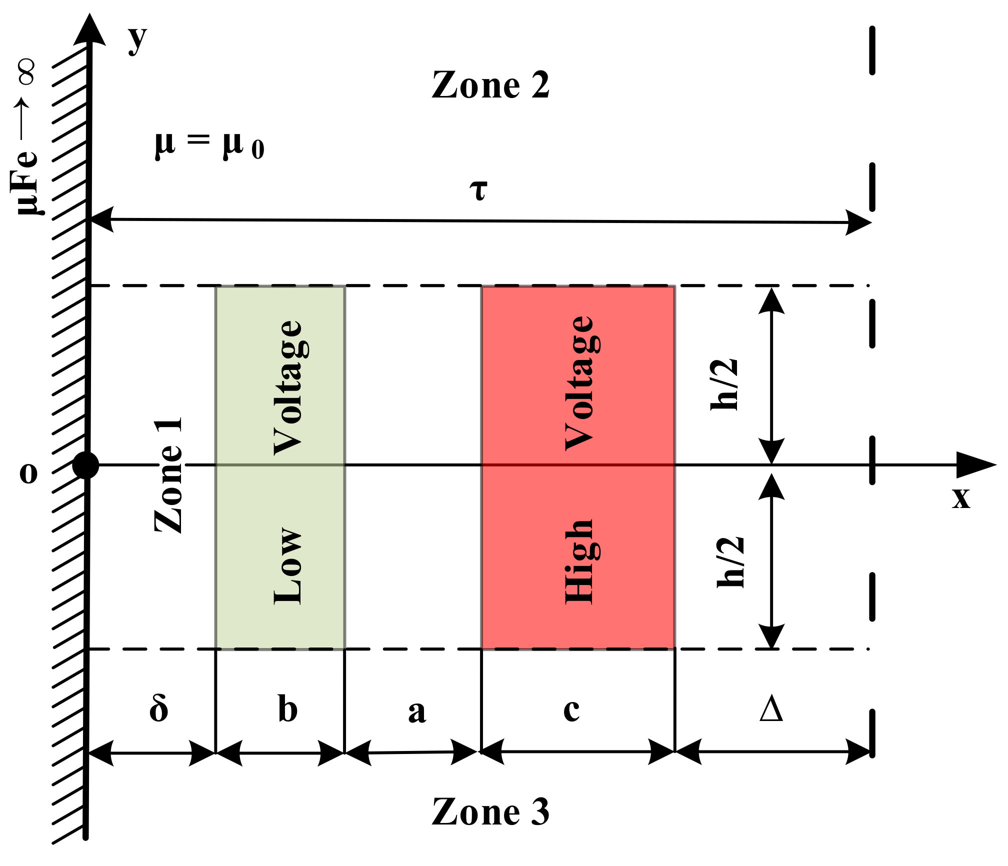
where
µ0 is the vacuum permeability,
D is the average diameter of the winding, and
N is the number of winding turns. The other geometric parameters are indicated in
Figure 2.
Due to the profound impact of leakage inductance on power converters, researchers are still actively looking into innovative methods for leakage inductance calculation [
11,
12,
13,
14,
15,
16]. In recent years, many studies have been reported on leakage inductance calculation that can be classified into numerical-based [
14,
15,
17] and analytical-based studies [
12,
13,
18,
19,
20,
21,
22]. Studies using numerical methods usually adopt finite element analysis and offer good accuracy; however, their computational cost is very high. The analytical methods, on the other hand, are easy to use with less computational effort and offer more flexibility in the design process of the transformer while still providing the estimation of leakage inductance with reasonable accuracy.
Compared with advanced complex methods, Rogowski’s equation offers an instinctual method for leakage inductance calculation. Nevertheless, Rogowski’s equation is only applicable to concentric winding transformers with windings of the same height. Moreover, the condition h/τ > 3.2 has to be met to ensure accuracy. To address the limitations of Rogowski’s equation, an analytical method is featured in this study that endeavors to develop a leakage inductance calculation equation using the winding dimension, spatial position, and magnetic medium of the field. The proposed method is intuitive, easy to use, and computationally efficient, and it can streamline the design process. The proposed method employs a double Fourier series for inductance calculation. It outperforms Rogowski’s solution, as it can be applied to transformers with double-group-overlapping windings and has no restriction against the length-to-width ratio of the field. Thus, it can be implemented in a wide range of applications.
2. Strategy Used to Develop Leakage Inductance Equation
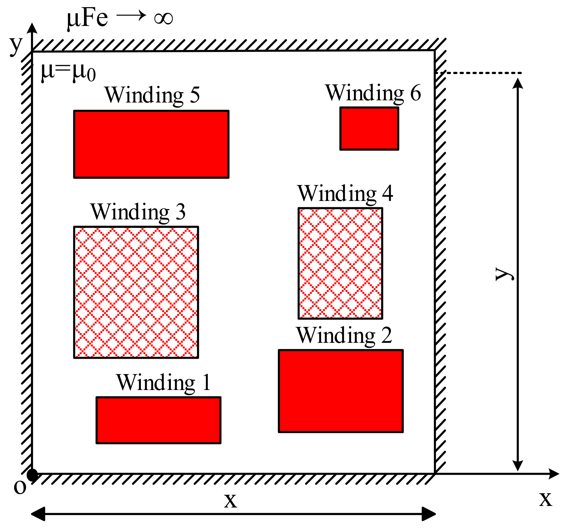
The fundamental concept for calculating the transformer leakage inductance given in this study was that the transformer leakage field could be simplified to a rectangular-plane field where the magnetic core window was located based on the axisymmetric characteristic of the transformer windings. The transformer working principle determined that the algebraic sum of the ampere-turns of the windings in this closed rectangular field was zero, i.e., ∑
N. I = 0. The windings were assumed to be uniformly distributed throughout the closed rectangular field depicted in
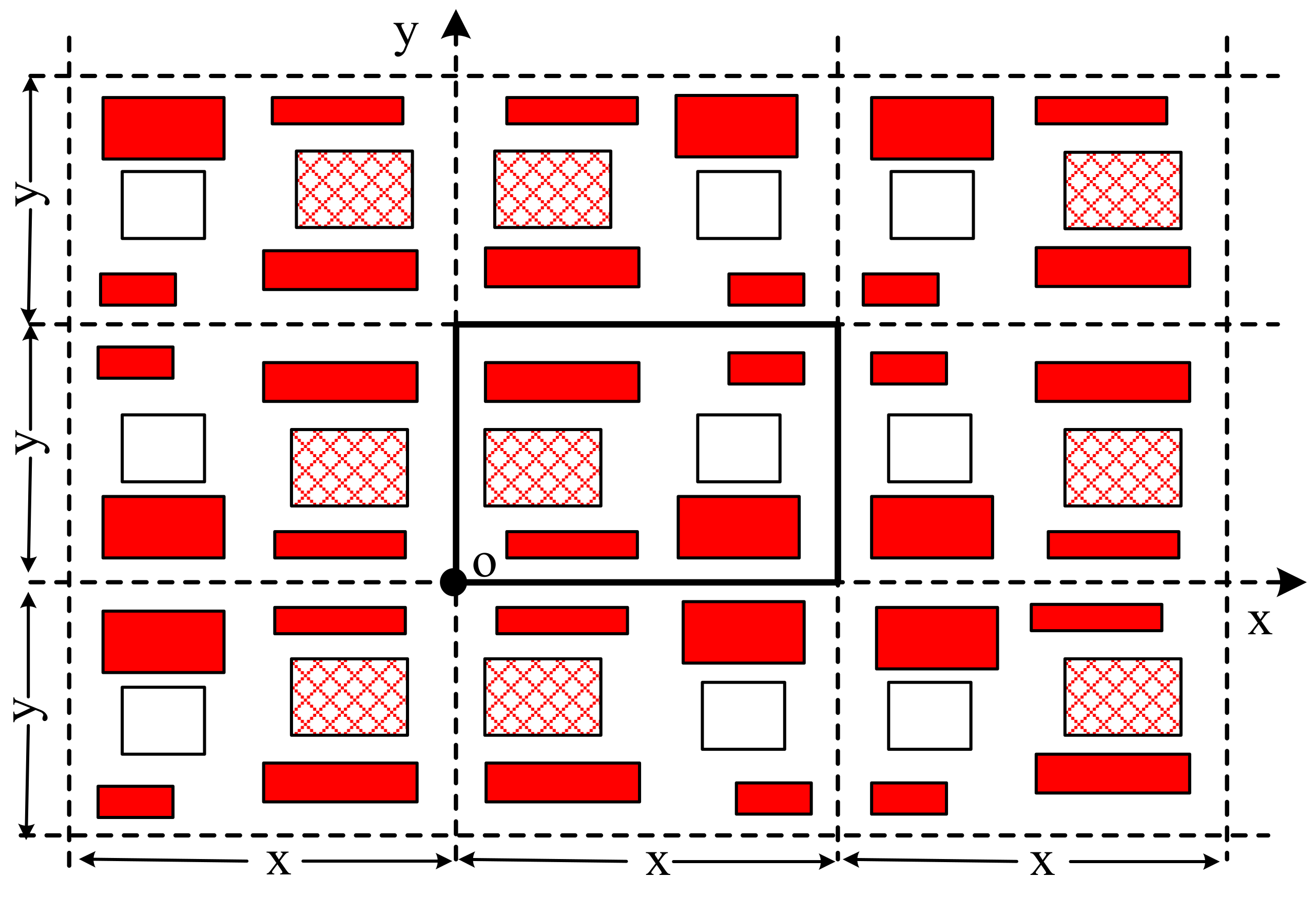
Figure 3 in order to ensure the broad applicability of the study. Hence, the closed rectangular field contained all the winding currents of the transformer. As indicated in
Figure 4, the winding current was mirrored toward the four sides of the magnetic core borders; thus, it formed a periodic current density distribution along the x- and y-axes. By expressing this discontinuous periodic current density distribution in a continuous current density distribution function using a double Fourier series, a unified magnetic vector potential of Poisson’s equation for the rectangular field could be developed. Then, the leakage inductance could be obtained by applying the boundary conditions of the magnetic core and the leakage field variable.
Compared to the single Fourier series method, the double Fourier series method featured in this paper did not require the division of the magnetic field into active and inactive zones. After expressing the discontinuous periodic current distribution with the double Fourier series, the whole closed rectangular field was equivalent to a unified active zone with continuous current density distribution, and a unified Poisson’s equation could be developed. The current density continued by mirroring the rectangular field to form a double periodic distribution in the orthogonal direction. The mirrored current density distribution and its expression with the double Fourier series are presented in the next subsection.
2.1. The Mirrored Current Density Distribution and Expression with Double Fourier Series
Assume there are
K windings in the rectangular field in
Figure 4. The area occupied by each winding is simplified to a rectangular area, and the current density of the
kth winding is
Jk. The double periodic current density distribution can be formed after this current density is mirrored several times, and it can be expressed with a double Fourier series as a general form [
10,
23]:
According to the constant magnetic field theory [
24], Poisson’s equation for magnetic vector potential
in the rectangular field is:
Determined by the form of the activation function on the right end of Poisson’s equation, the magnetic vector potential
Az (
x,y) also has the form of a double Fourier series, and the general form expression is:
According to the electromagnetic field theory [
24], the magnetic field does not have a tangential component on the magnetic border with
, and the boundary conditions of the four borders in the field can be determined:
The magnetic vector potential in the field can be solved according to (3)–(5):
2.2. Unified Expression of Leakage of Magnetic Field Energy and Leakage Inductance of Transformers
The magnetic field leakage is related to the winding current, but the leakage inductance is independent of the winding current. Assuming that the total number of turns of the winding is
N and the current is
I, the leakage inductance
Lσ can be obtained by applying the magnetic field energy equation
Wσ = ½(
Lσ × I2) after the leakage magnetic field energy is solved. According to the electromagnetic theory [
24], for a linear medium, the magnetic field energy of the three-dimensional space is:
Using the orthogonality of trigonometric function series, i.e., only the integrals of the products of the same cosine term are not zero, the unified expressions of the leakage magnetic field energy and the leakage inductance of transformers can be obtained:
The above unified expressions of the magnetic field energy and leakage inductance contain the coefficients of the double Fourier series. The current density distribution of a specific winding form can be transformed into the double Fourier series. Then, the leakage inductance expression of a specific winding can be calculated by substituting the coefficients into the leakage inductance equation.
3. Derivation of Leakage Inductance Equation for Transformers with Double Group Overlapping Windings
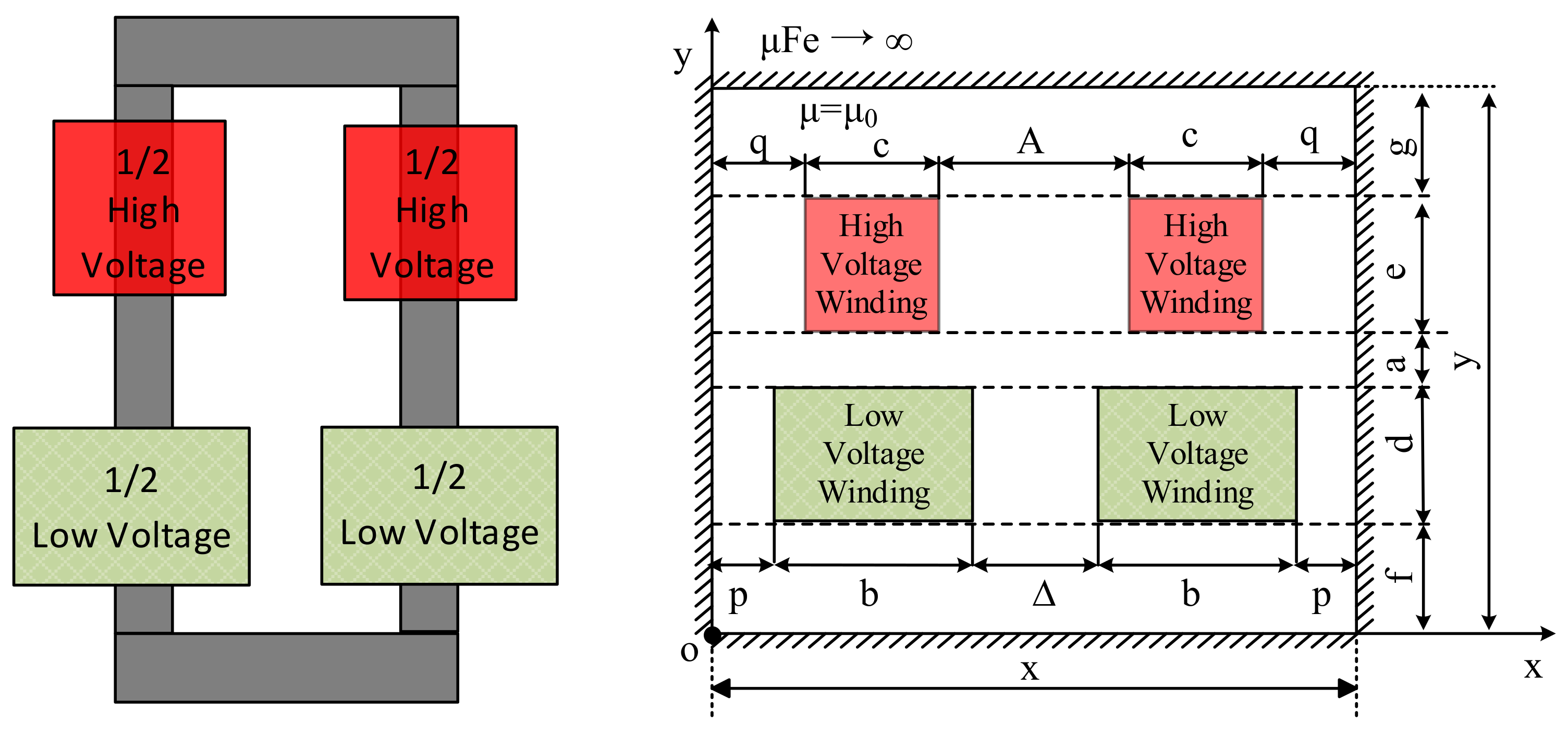
The structure of a transformer with double-group windings and its simplified plane field are indicated in
Figure 5, where important parameters impacting the leakage inductance value include X, Y, winding dimension, and parameter f. The f already incorporates the effect of other parameters, such as a and g. For instance, when parameter f varies while the other parameters are kept unchanged, parameter a varies accordingly, which is equal to the change in the distance between the windings. Similarly, if parameter g changes, parameter a varies accordingly, as depicted in
Figure 5.
Assume the number of turns of the high-voltage windings is
N, the current is
I, and the winding average diameter is
D, the current density of the high-voltage winding is
Jc = (−NI)/(2
ce), and the current density of the low-voltage winding is
Jb = (NI)/(2
bd). The coefficients of the double Fourier series of the current density distribution for the plane field shown in
Figure 5 can be calculated using (10)–(12). The calculation steps are as follows:
where:
where:
where:
The coefficients of the double Fourier series of the current density distribution are shown in (13)–(18). By substituting these coefficients in unified expression (9), expression (19) can be obtained, which is the final leakage inductance equation that can be used for calculation.
Expression (19) is the equation for calculating the transformer leakage inductance in the form of an infinite series, and convergence can be verified. The sum of the first n terms is taken as the approximate value for the transformer leakage inductance calculation. The convergence rate can differ for transformers with windings in different form factors or dimensions.
4. Simulation and Experimental Analysis
In this section, the leakage inductance of a double-group winding transformer calculated using the proposed method is verified against simulation and practical measurement results. The transformer dimension and the form of the windings were changed separately to make a sensitivity analysis and comparisons.
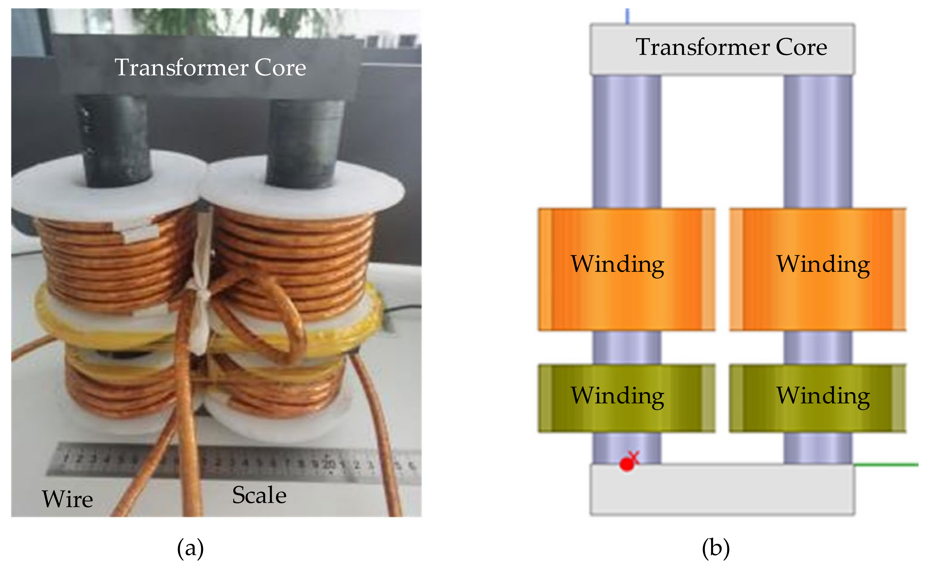
Figure 6 shows the real transformer and the simulation model built based on the transformer dimension parameters using Ansys software. The transformer used in the test had a magnetic core diameter of 40 mm, a magnetic core length Y of 230 mm, and a magnetic core window X of 70 mm. The wire used was a multi-strand wire with a diameter of 7.84 mm. The other parameters are outlined in
Table 1.
As can be seen in
Table 2, the results obtained from the proposed calculation method in this study were very close to the simulation results, yet the simulation and calculated results showed slight variations from the measurement results. The reason behind this variation was that the leakage magnetic field of the transformer was three-dimensional and was not strictly axisymmetric. This work made the axisymmetric field assumption for the leakage magnetic field, which facilitated calculation by simplifying the calculation procedure and provided an intuitive and easy method. Likewise, simplification was also conducted in different simulation methods to minimize the computational cost and simulation time. That is why the results obtained from the proposed method and the simulation showed minor differences from the actual measurements.
In addition, the value of leakage inductance also depended on different factors, such as f, X, Y, and the winding form. The impact of these factors on the leakage inductance value could be revealed by conducting a sensitivity analysis, which is discussed in the subsequent subsection.
4.1. Sensitivity Analysis for Change in Transformer Parameter f
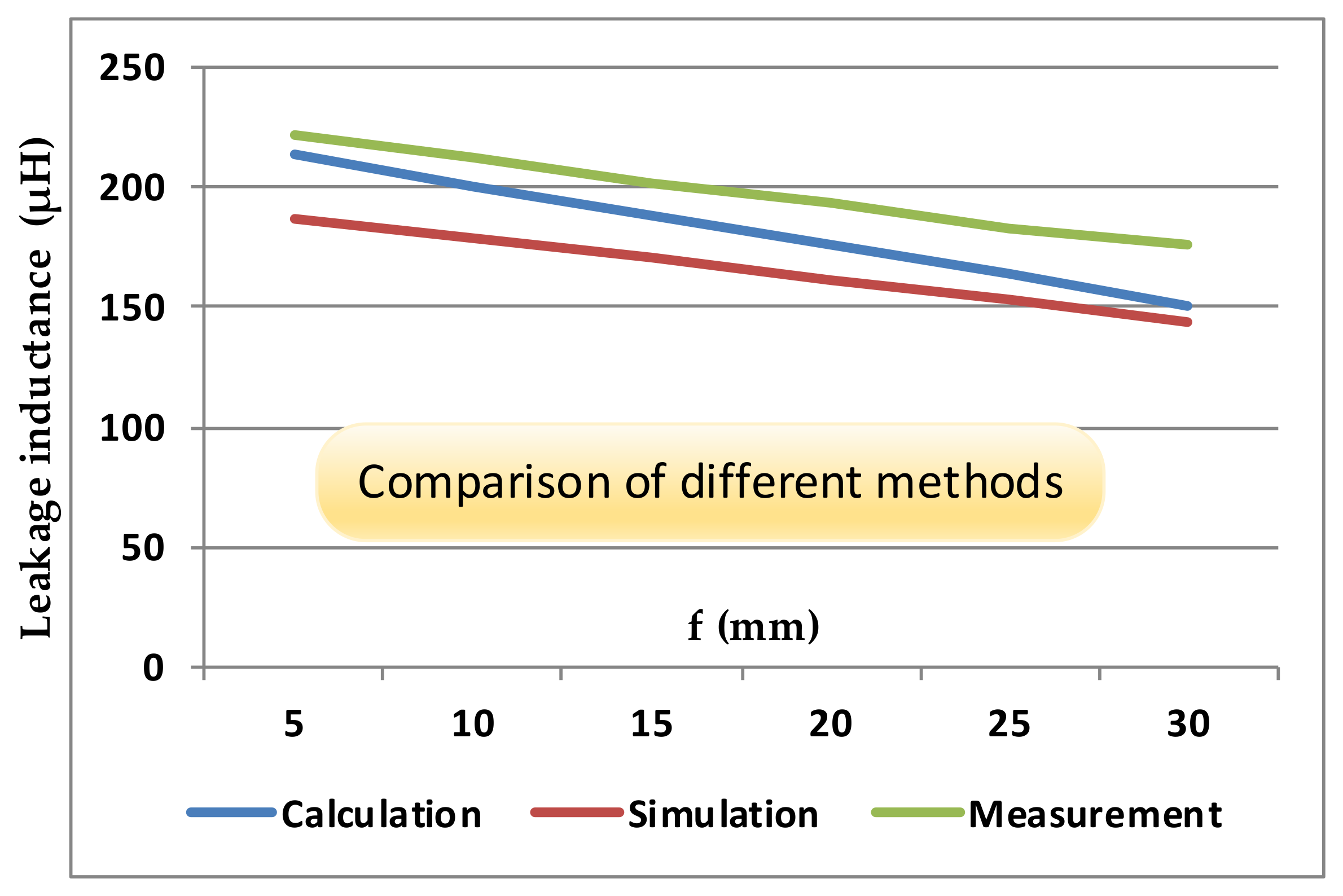
By changing the transformer parameter f and keeping the other parameters unchanged, the results of the calculation, simulation, and measurements are presented in
Table 3, revealing that all three methods showed a decrease in the inductance value with increasing parameter f. The trend of change in value for all the methods remained the same. The minor variation among the results of the different methods was due to the assumptions made in the simulation and calculation methods for simplification, as mentioned earlier in the discussion of the results of
Table 2.
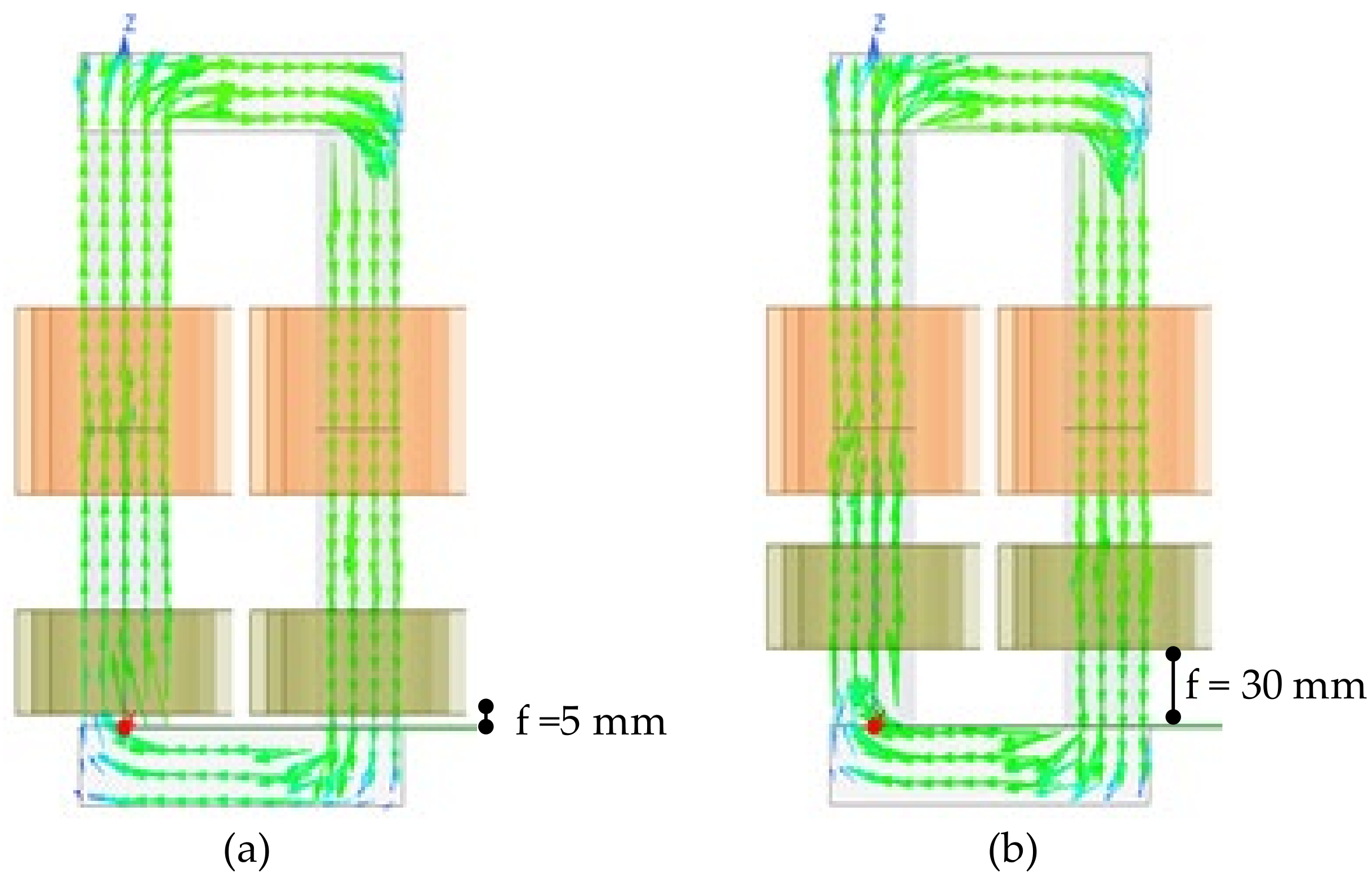
The transformer magnetic field intensity distributions with f = 5 mm and f = 30 mm are indicated in
Figure 7.
With the increase in parameter f, the visualization of the transformer magnetic field intensity distributions are depicted in
Figure 7. In addition, a comparison of leakage inductance values with different methods is presented in
Figure 8. With the increase in parameter f, the distance became shorter between the high-voltage and low-voltage coils; as a result, the value of the leakage inductance changed. It can be seen from
Figure 8 that the variation trend of the transformer leakage inductance remained the same for the calculation results, simulation results, and measurements. Hence, comparing different methods validated the efficacy of the proposed calculation method, even under variation in the f parameter.
4.2. Sensitivity Analysis for Change in Transformer Parameter X
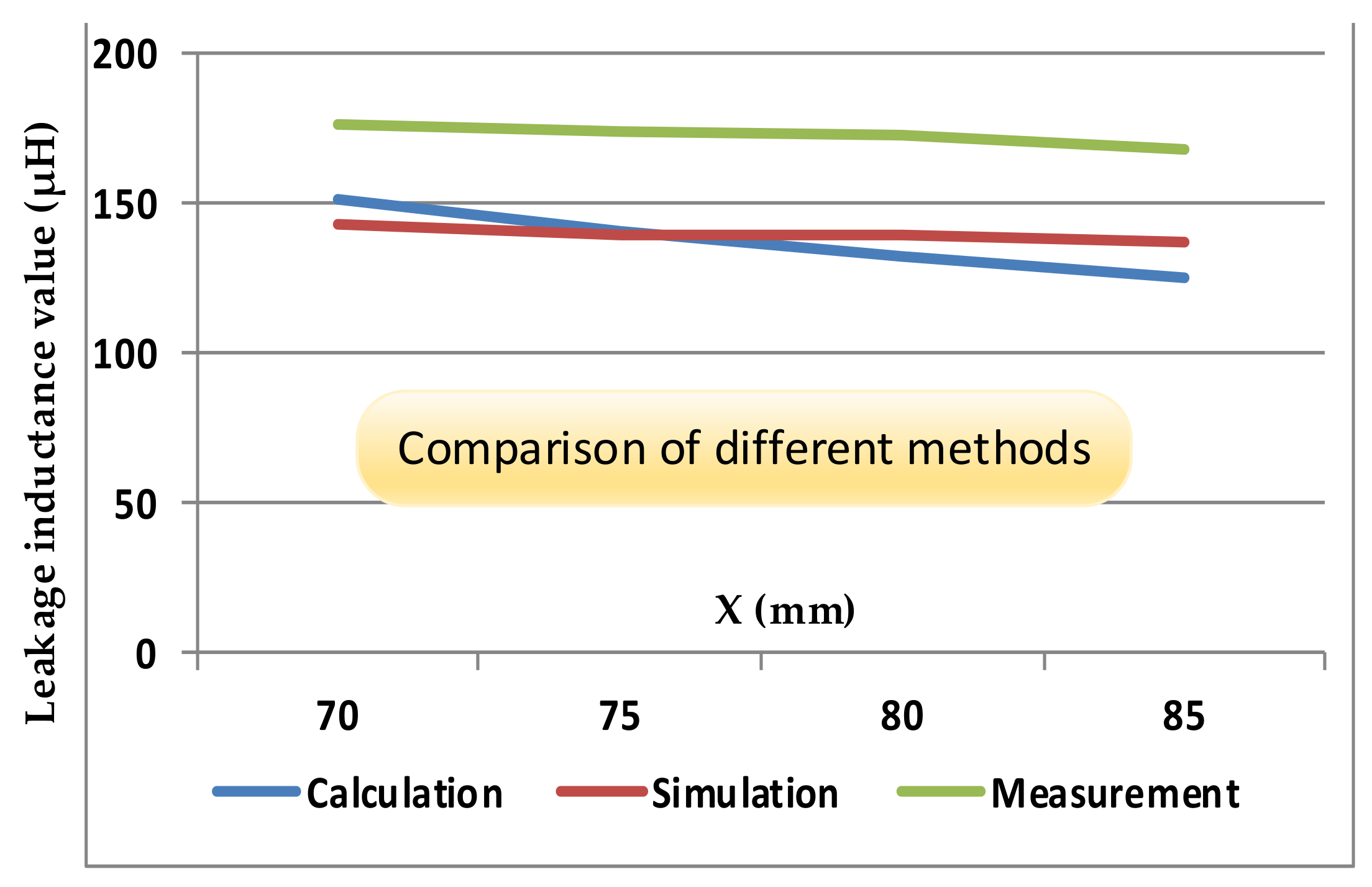
This subsection presents the calculation, simulation, and measurement results when changing the transformer parameter X and keeping the others unchanged. Parameter X dictated the dimension of the transformer along the x-axis. In transformer design, a smaller parameter X meant a smaller x dimension of the transformer. The transformer magnetic field intensity distributions with X = 70 mm and X = 85 mm are indicated in
Figure 9. The value of the transformer leakage inductance reduced with the increase in parameter X. With variation in parameter X, the leakage inductance value was calculated using the proposed calculation method and compared with simulation and measured results, and the results are outlined in
Table 4. To observe the trend, the results are plotted in
Figure 10, showing that the change in leakage inductance value with the proposed calculation method was consistent with the simulation and measured results. Therefore, the comparison of different methods validated the efficacy of the proposed calculation method under variation in the X parameter.
4.3. Sensitivity Analysis for Change in Transformer Parameter Y
To analyze the sensitivity of parameter Y on the leakage inductance value, parameter Y was gradually increased, keeping the other parameters unchanged. The calculation, simulation, and measurement results are outlined in
Table 5. The results showed that the change in parameter Y had a negligible impact on the transformer leakage inductance. Hence, it can be concluded that leakage inductance was almost independent of parameter Y. The proposed method’s conclusion was consistent with that of the other two methods.
4.4. Sensitivity Analysis for Change in the Form of Transformer Windings
This subsection presents the impact of form change in transformer windings on the leakage inductance value. Simulation models and experimental prototypes were built to study the form factor’s effect on the leakage inductance value, as shown in
Figure 11.
First, the leakage inductance value was calculated using the proposed method considering the change in the form of the transformer windings; then, the results were compared with simulation and experimental ones. The proposed calculation method indicated that, by 2× changing the form of the transformer windings (
N), the leakage inductance value changed almost 4×. As outlined in
Table 6, the simulation results and experimentally measured values showed almost 4.3× and 3.7× changes, respectively, in the leakage inductance values for 2× change in the form of the transformer windings (N), which was quite close to the estimation provided by the proposed method. Hence, the proposed calculation model offered a reasonable estimation of leakage inductance values, even under different parameter variations. The reason behind the minor difference in the values was that the leakage magnetic field of the transformer was three-dimensional and was not strictly axisymmetric. In this study, the leakage magnetic field was assumed to be an axisymmetric field, which simplified the calculation and provided an intuitive and easy method with less design and calculation effort for leakage inductance while still offering good estimation.
5. Conclusions
Double-group-overlapping winding transformers are often used as isolation transformers in power electronic transformers. In this paper, a model for calculating the leakage inductance of double-group winding transformers was derived using the double Fourier series method. The estimated transformer leakage inductance value using the proposed method was pretty close to the simulation and measurement results. Compared with other methods, the proposed method provided an intuitive and easy way with less design effort for leakage inductance calculation and still offered good accuracy.
Reviewing the whole process, the main cause of the difference between the calculation results and the actual value could be summarized as follows: the leakage magnetic field of the transformer was three-dimensional and was not strictly axisymmetric field. Especially with the impact of the magnetic yoke, the leakage magnetic field further deviates from the axisymmetric state. However, to simplify the mathematical calculation, the leakage magnetic field was assumed to be an axisymmetric field.
In practical engineering applications as a numerical analysis method, the double Fourier method for calculating transformer leakage inductance could be used as a reference design. Moreover, the double Fourier series method resolved the limitations of Rogowski’s equation, as it could be applied to transformers with different winding heights, increasing the range of applications.


