Article

Classification of Single Current Sensor Failures in Fault-Tolerant Induction Motor Drive Using Neural Network Approach

Department of Electrical Machines and Drives, Wroclaw University of Science and Technology, Wyb. Wyspianskiego 27, 50-370 Wroclaw, Poland
*
Author to whom correspondence should be addressed.
Energies 2022, 15(18), 6646; https://doi.org/10.3390/en15186646
Submission received: 29 July 2022 / Revised: 26 August 2022 / Accepted: 5 September 2022 / Published: 11 September 2022
(This article belongs to the Special Issue Frontiers in Automatic Control in Drives and Power Electronics)

Abstract

:
In the modern induction motor (IM) drive system, the fault-tolerant control (FTC) solution is becoming more and more popular. This approach significantly increases the security of the system. To choose the best control strategy, fault detection (FD) and fault classification (FC) methods are required. Current sensors (CS) are one of the measuring devices that can be damaged, which in the case of the drive system with IM precludes the correct operation of vector control structures. Due to the need to ensure current feedback and the operation of flux estimators, it is necessary to immediately compensate for the detected damage and classify its type. In the case of the IM drives, there are individual suggestions regarding methods of classifying the type of CS damage during drive operation. This article proposes the use of the classical multilayer perceptron (MLP) neural network to implement the CS neural fault classifier. The online work of this classifier was coordinated with the active FTC structure, which contained an algorithm for the detection and compensation of failure of one of the two CSs used in the rotor field-oriented control (DRFOC) structure. This article describes this structure and the method of designing the neural fault classifier (NN-FC). The operation of the NN-FC was verified by simulation tests of the drive system with an integrated FTC strategy. These tests showed the high efficiency of the developed fault classifier operating in the post-fault mode after compensating the previously detected CS fault and ensuring uninterrupted operation of the drive system.

1. Introduction

In recent years, there has been a growing interest in fault-tolerant drive systems. This is understood to be a guarantee of system operation at least for a short period of time, despite the failure of selected parts of the system [1,2,3]. A standard approach to achieve fault tolerance is to equip the control system with explicit fault detection and compensation capabilities. After detecting and isolating a damaged drive element, it is necessary to compensate for the damage in order to provide the system with full or partial functionality. In the case of the drive system, the converter, motor, and measuring sensors may be damaged. Therefore, in recent years, solutions have been sought that allow for not only damage detection but also compensation. A broad overview of FTC detection methods and FTC strategies, including structural and algorithmic solutions, referred to as converters, machines, and sensors, is presented in [4], with reference to PMSM drives. However, FTC’s strategies for the failure of frequency converters and sensors in particular are very similar for both PMSM and inductive drives. In general, FTC strategies can be classified as passive and active [1,2,3,4]. In the case of current sensor faults, which are considered in this research, only active methods are possible. They are based on controller reconfiguration or hardware and software redundancy.
As an example of reconfiguration of the control system, we can provide the switch from the IM vector control strategy to scalar control in the case of failure of both sensors of the stator phase currents in the drive system [5]. In this case, the drive system may work, but it does not have the previous properties provided by the vector control structure. The hardware solution in the event of CS failure consists of hardware redundancy in the form of an additional third or even fourth CS (in industrial IM drives, current measurement is usually performed only in two phases of the stator winding) [6]. The other approach consisting of reconstructing the stator phase current was also used on the basis of measuring the current in the DC bus of the VSI [7,8]. However, this solution also requires an additional current sensor in the DC circuit, which is not used in standard drives. In recent years, software solutions have been sought that can be used for the detection of damage to current sensors as well as for the location of damage and its compensation.
Active FTC methods require an FD system and then an fault compensation solution. In the case of CS faults, so far few fault detection methods have been developed [6,9,10,11,12,13,14,15,16]. One of the most popular CS FD solutions is that based on the mathematical model of IM [9,10,11,12,13]. For example, in [10], the authors propose an application of the observer to calculate stator currents and rotor resistance. The input of the observer is two measured phase currents, rotor speed, and stator voltage. The solution presented is based on a mathematical model written in the (d-q) frame. To detect a CS fault, the difference between the amplitudes of the estimated and measured currents is used. It should be noted that the presented method can only be used when one CS is healthy. Another solution based on a group of three rotor flux observers has been presented in [11]. In this research, every observer is based on two different phase currents. When some of the CSs are broken, two observers show the wrong values. This allows us to determine which CS is faulty. Another way to detect and localize the fault of CS is to calculate the difference [12] or the square of difference [13] between the measured and estimated stator currents.
Because IM is a symmetric receiver, the sum of the three phase values is equal to zero, so this relationship is one of the most commonly used in FD systems [6,15,16]. For example, the authors in [6] propose Cri markers based on different ways of converting phase values to the (α-β) frame. This solution can be used in the detection system [6,17,18] but requires the measurement of three phase currents, while most drive systems use two CS and three-phase symmetry conditions. When only two CSs are available in the control structure, detection is also possible [14]. In [14], the asymmetric index is used for the detection and localization of faults. The RMS values of two current sensors should be the same. When the difference between them is greater than the assumed threshold, this is information for the FTC system that a failure has occurred. Note that the presented method can only be used for gain errors.
Other methods used in FD for CS faults are based on neural networks (NN) [18,19,20,21]. In [19], fault detection is performed by NN and isolation is performed by the fuzzy logic technique. In [20], Time-Delay NN has been used to detect four types of faults: outlier, constant offset, constant noise, and stuck-at-zero. Two of them, constant offset and stuck-at-zero, have been detected properly, but noise sporadic and outliers have not. The authors in [21] presented NN for CSs fault detection. As the authors concluded, the presented NN has been trained only for totally broken CS and cannot detect all kinds of CS faults. On the other hand, work [18] shows an NN-based solution for PMSM drive with a relatively high detection effectiveness of CS faults. However, the authors propose four different MLP structures for four different CS faults (lack of signal, intermittent signal, noise, and gain error), so one NN detects only a certain fault. Therefore, this solution is not able to accurately classify any damage and, moreover, the proposed compensation method requires the use of three CS.
The method presented in [22] is directed at CS fault classification in the IM drive and consists of classifying the type of sensor damage in successive time windows using machine learning technology named the extreme learning method (ELM). If the damage could not be correctly classified in the first time window, then an attempt was made to diagnose it in the second, and so on. The presented method allowed detecting three types of current, speed, and voltage sensor damage: stuck, offset, and noise, in the traction drive for constant speed. The accuracy of this method is approx. 98%, and the average fault detection time is 10 ms. However, the learning method of the proposed algorithm highly depends on random initial conditions, and thus, the achieved accuracy and learning time can also be random. In addition, the presented method has not been used to detect gain-type defect of CS, and post-fault drive operation and fault compensation methods are not discussed.
On this occasion, it should be stated that the classification of CS-type failure is quite important in any drive system, as some failures can be easily compensated for, even without the use of complex mathematical models [10]. Therefore, in this article, the problem of classification of different types of CS faults constitutes the main goal of the research, and an NN-based fault classifier (NN-FC) is proposed.
To compensate for CS faults in drive systems, the most popular solution is based on the mathematical model of IM [9,12,23,24,25,26,27,28]. For example, to compensate for the loss of all phase currents, the flux-linkage observer [23] is proposed. However, the authors mention a high sensitivity to changes in the IM parameters. Another method, called a virtual current sensor (VCS), has been proposed in [24]. This solution is based on voltage and current models of the rotor and allows us to maintain of vector control strategy also in a situation when all CSs are faulty. Furthermore, VCS has been extensively experimentally studied in both control structures: DRFOC [24,25] and DTC [26]. Other methods that do not require the measurement of any phase current are based on the Luenberger observer [12,27] and its modified version [28]. Another way to compensate for the failure of CS is to use the stator current reference values and the transformation of the IM reference frame [29,30]. It should be noted that for this solution, the information of even one phase current is required.
The presented literature overview shows that there are several FTC solutions for IM drives in the event of a failure of the stator current sensors. Usually, the detection of sensor damage is based on the residuum determined on the basis of the measured and calculated current from the mathematical model [5,6,7,8,9,10,11,12,13,14,15,16,17], including a solution based on NNs (as these residuals are used in the input vectors of NN) [16,17,18,19,20,21]. The result of this detection is information about sensor damage, and it must be compensated by using hardware (with the use of an additional CS in DC link [7,8] or in the phase C [17,18]) or software [9,10,11,12,13,14,15,16,23,24,25,26,27,28,29,30] redundancy. On the other hand, the methods based on the IM mathematical model dominate among the damage compensation methods of CSs [23,24,25,26,27,28,29,30]. However, apart from the work [22], the literature lacks methods of assessing CS failures in the IM drive, especially one that operates in a wide range of speed and load torque changes.
Therefore, the main objective of the research presented in this article was to develop a neural classifier of the most common types of damage to stator current sensors (total signal loss, offset, saturation, gain change) in an inductive drive with DRFOC control, which would perform its task for variable operating conditions of the drive.
The article presents the following original achievements of the authors:
-
The original concept of the active FTC system, in which the classification of the type of damage to the current sensor takes place after the detection of a failure in any phase of the motor in the drive with vector control (DRFOC) and implementation of software redundancy, i.e., switching the control structure to work with estimated currents using the VCS algorithm, which allows eliminating the influence of CS damage on the control structure and limits the number of symptoms used in NN-FC;
-
The neural classifier developed using the MLP network, based on the estimated stator currents, which during the operation of the drive in the post-fault mode detects the type of CS damage (total lack of signal, gain change, saturation, and off-set) and the place of its occurrence in the time less than 1.5 the stator current period;
-
The on-line operation of the CS neural fault classifier was demonstrated, and the smooth operation of the drive system with vector control before and after failure detection was demonstrated.
The article consists of six sections. After this introduction, the mathematical description of the IM drive system and analyzed CS faults are presented in Section 2. Next, the concept of FTC strategy with CS fault detection and compensation algorithms are presented. The main part of the article constitutes Section 4 and Section 5. The proposed NN-based classifier of CS faults is presented in detail in Section 4, including the structure and training process of the MLP networks analyzed. On-line verification of the NN-FC is demonstrated in Section 5. The article ends with conclusions and an indication of future research plans.

2. Mathematical Model of Induction Motor Drive System with Current Sensor Faults

2.1. Mathematical Model of the Induction Motor

The implementation of simulation studies requires the use of a mathematical model of IM which is usually formulated with well-known assumptions on lumped and constant winding parameters, three-phase symmetry of the windings, sinusoidal distribution of the magnetic field in the motor air gap, hysteresis, and eddy current neglected. Therefore, the mathematical model of IM, written using the spatial vector notation in a stationary reference frame (α-β), can be written as follows [31,32]:
  • Voltage equation of the stator and rotor windings:
d d t Ψ s = ( u s r s i s ) 1 T N
d d t Ψ r = ( r r l r ( l m i s Ψ r ) + j ω m Ψ r ) 1 T N
  • Flux-current equations:
Ψ s = l s i s + l m i r
Ψ r = l r i r + l m i s
where ls = lm + lσs, lr = lm + lσr,
  • Equation of motion:
d d t ω m = ( t e m t L ) 1 T M
  • Electromagnetic torque:
t e m = ( Ψ s * i s )
where: TN = 1/(2πfsN).
This mathematical model will be next used in the DRFOC structure for modeling the controlled motor and for the development of the mathematical model of stator current estimation in the case of CS faults. This current estimation algorithm will be used in the proposed active FTC structure based on software redundancy [4,12,13,23,24,25,26,27,28,29,30].

2.2. Direct Rotor Flux Oriented Control Structure

The main idea of the DRFOC method consists of controlling the IM torque and rotor flux with the components of the stator current vector oriented with respect to the rotor flux vector in a synchronously rotating coordinate system (x-y). This makes it possible to control the electromagnetic torque with the isy component of the stator current vector according to:
t e m = l m l r Ψ r i s y
with simultaneous stabilization of the rotor flux amplitude by the isx current component.
Implementing this control method requires the use of transformations of the phase coordinate system to a stationary frame (α-β) and then to the rotating frame (x-y). Because the IM is a symmetric receiver, two CSs are used in most drive systems. Thus, these transformations of any state variable v are as follows:
-
Clarke transform:
[ v α v β ] = 1 3 [ 3 0 1 2 ] [ v A v B ]
-
Park transform (VT):
[ v x v y ] = [ cos γ Ψ sin γ Ψ sin γ Ψ cos γ Ψ ] [ v α v β ]
and the inverse transformations, respectively:
[ v A v B ] = 1 2 [ 2 0 1 3 ] [ v α v β ]
[ v α v β ] = [ cos γ Ψ sin γ Ψ sin γ Ψ cos γ Ψ ] [ v x v y ]
The schematic diagram of the classic DRFOC structure is shown in Figure 1.

2.3. Types of Current Sensor Faults and Their Modeling

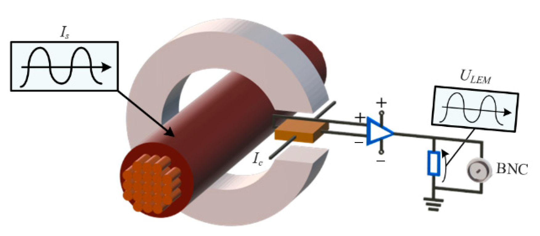
Contactless transducers of the LEM type are usually used to measure the stator current. An example of its structure is shown in Figure 2. This type of transducer uses the Hall effect—the magnetic flux created by the current flowing through the wire is concentrated in the magnetic core in a gap with a Hall plate placed there. A potential difference is created on the plate, and the current flowing through the plate is amplified by the electronic circuit. Finally, a resistor is used to measure the voltage drop, which then forms an analog signal ready to be converted to a digital value.
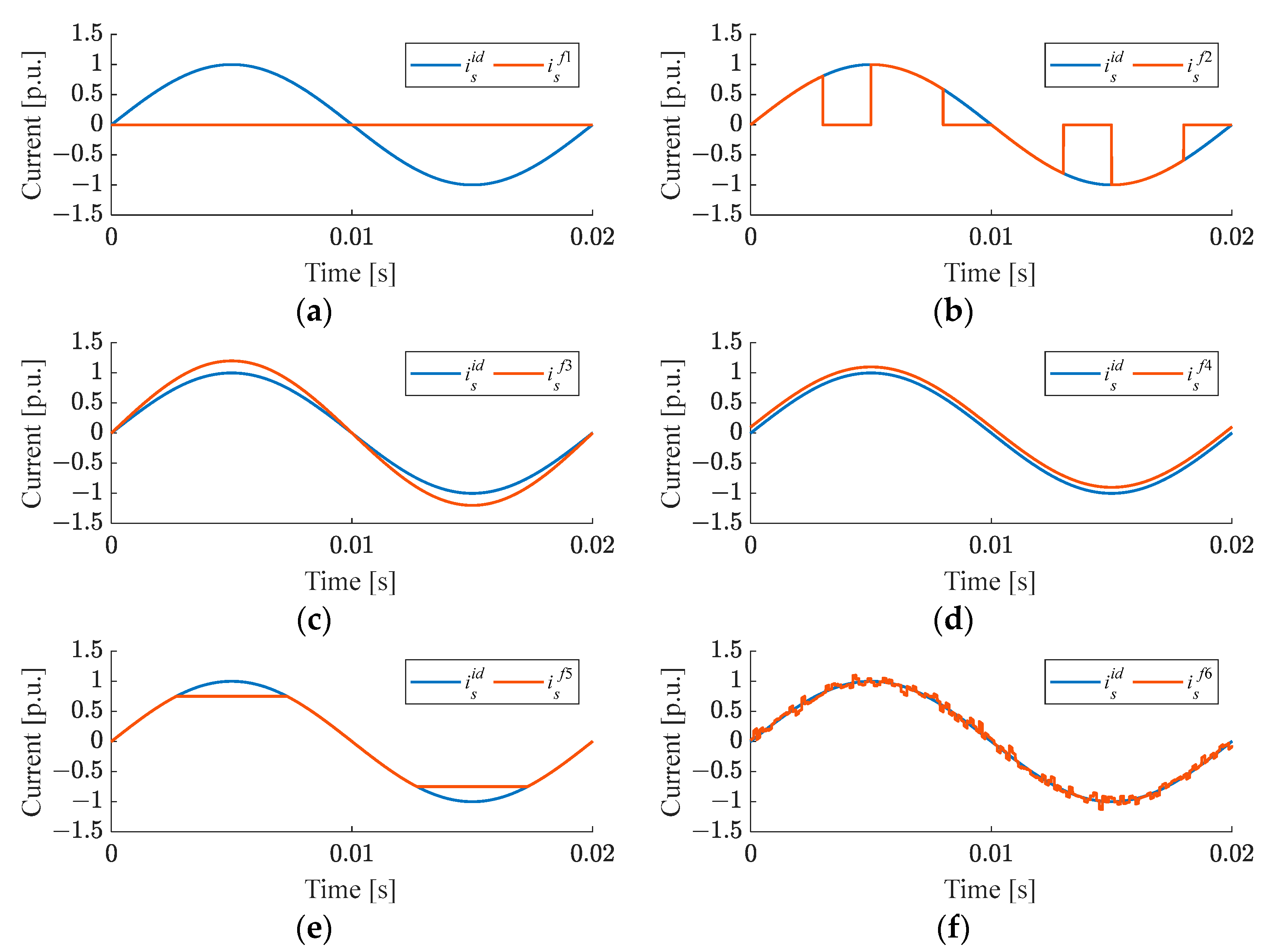
Due to their topology and operating principle, six types of transducer failures can be classified [33], which along with mathematical models of these failures are presented in Table 1.
Based on the mathematical models of the CS faults, the waveforms of ideal (superscript id) and faulty (superscript fi; where i is a fault number according to Table 1) stator current waveforms are presented in Figure 3.
As can be seen above, an open circuit and disconnections of the signal lead to zero value of the stator current. Noise always occurs in the real drive, and if it is within the prescribed limits, it usually does not have a significant effect on system performance. Due to this fact in this research, four types of CS fault have been classified: open circuit, gain change, offset, and saturation.

3. Current Sensor Fault Tolerant Control

3.1. General Description of Developed FTC Strategy

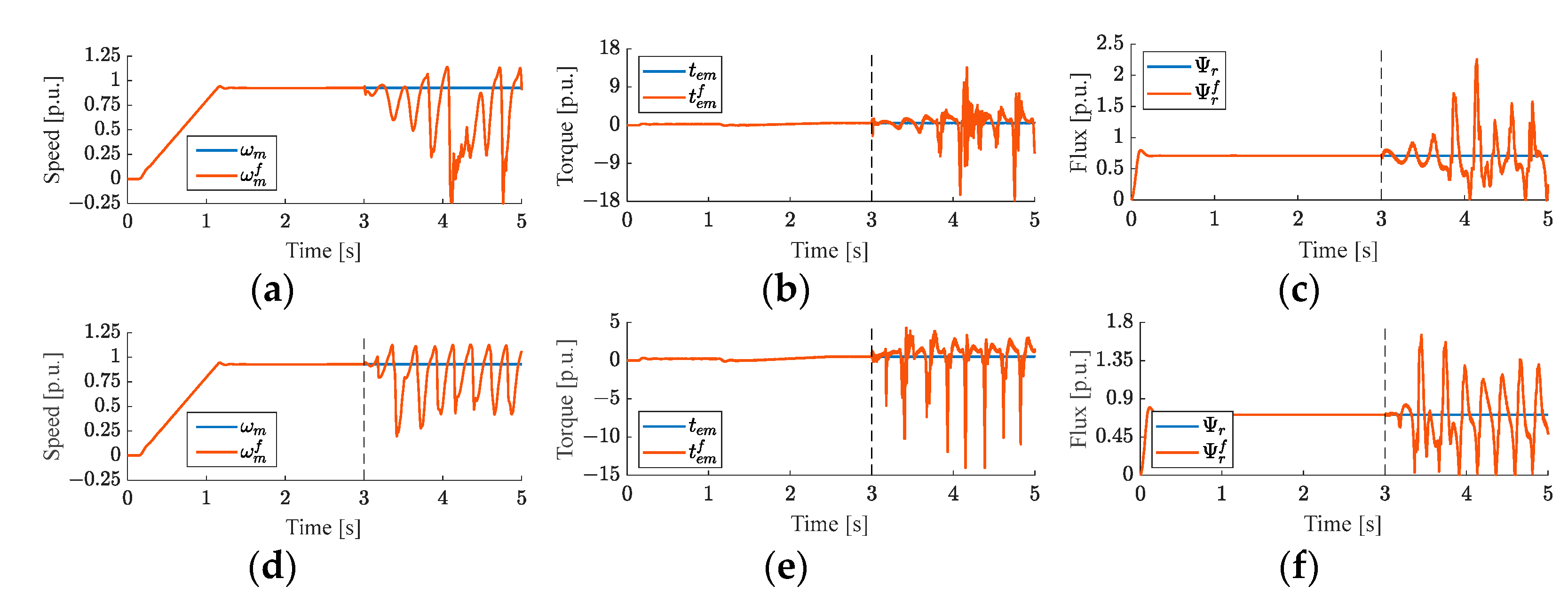
In the DRFOC structure, precise measurement of the stator current is essential for proper drive system operation. The occurrence of CS failure can even cause a loss of drive system stability. In Figure 4, the exemplary waveforms of the state variables in normal operation are compared with the waveforms of these variables in the case of a certain CS fault (index f). The influence of an open phase fault and CS saturation that occurred at t = 3s in phase A of the stator winding is shown in Figure 4.
As can be seen, the occurrence of CS damage causes very negative effects, forcing the need to compensate for the damage as soon as possible. In addition, fast compensation of the CS fault allows the closed-loop system to remain stable and operate properly in the industrial process. Accordingly, in the presented research, a three-stage FTC strategy has been proposed, which enables not only fault detection but also its compensation and fault type classification, as presented in Figure 5.
The first stage of the FTC procedure consists of the detection of the CS fault in any motor phase. The FD algorithm is based on the calculation of the residuals between the measured and estimated stator currents. The detailed algorithm will be described in the next subsection. Next, the measured stator currents are replaced by the estimated ones to ensure proper operation of the DRFOC structure and uninterrupted operation of the drive system. In the course of further operation of the drive with the use of the estimated stator currents, the third stage of the FTC procedure is carried out—classification of the type of CS fault using a neural network-based fault classifier. In all three stages, the stator current estimator called VCS [24] is used, which will be briefly described in the following subsection.

3.2. Virtual Current Sensor

For FTC operation of the analyzed drive system, the stator current estimator is required not only for the CS fault detection and fault compensation algorithms but also for the fault classification stage. In this investigation, the VSC algorithm proposed and tested in [24,25,26] is applied. It consists of the stator current estimator, which is supported by the rotor flux model [25]. In this algorithm, the components of the estimated current vector, i s e in the (α-β) frame are obtained as follows:
d d t i s α e = 1 l s σ ( u s α r s i s α e T N l m l r d d t Ψ r α i ) 1 T N
d d t i s β e = 1 l s σ ( u s β r s i s β e T N l m l r d d t Ψ r β i ) 1 T N
while the components of the rotor flux vector are calculated using well-known current model of the rotor flux, Ψ r i :
d d t Ψ r α i = ( r r l r ( l m i s α e Ψ r α i ) ω m Ψ r β i ) 1 T N
d d t Ψ r β i = ( r r l r ( l m i s β e Ψ r β i ) + ω m Ψ r α i ) 1 T N
where σ = 1 − lm2/(lslr) is the leakage factor.
To implement the above algorithm, it is necessary to know the actual values of the components of the stator voltage vector, which can be determined from the measurement of the DC bus voltage, uDC of the VSI and by duty cycle values dA, dB, and dC:
u s α = 1 3 ( 2 d A d B d C ) u D C
u s β = 3 3 ( d B d C ) u D C
In the VCS algorithm, an angular velocity measurement is also required. However, it is not a disadvantage of the presented solution, because it is directed to the FTC-type systems, and those are equipped with basic measuring equipment, such as an encoder for speed measurement or LEM-type transducers for current and voltage measurements. The schematic diagram of the VCS algorithm is shown in Figure 6.
As all IM model-based state estimators, VCS is also sensitive to changes in motor parameters. It was tested in detail in [25], and it was concluded that the rotor resistance has a major impact on the quality of the stator current estimation. The effect of changes in rotor resistance can be compensated by estimating this parameter in the control structure with VCS, as has been shown in [25,34].
Therefore, in further research, it was assumed that the rotor resistance sensitivity of the VCS was compensated by supplementary online parameter estimation.

3.3. Fault Detection and Compensation

The first task of the proposed FTC strategy, CS fault detection (FD), is realized by comparing the instantaneous values of the measured and estimated current signals. For this purpose, the sum of the estimation errors between the measured and estimated α-β components of the stator current vector is calculated:
ε α β ( k ) = ( i s α ( k ) i s α e ( k ) ) 2 + ( i s β ( k ) i s β e ( k ) ) 2
while the measured phase currents are transformed using (8), and the estimated α-β components are taken from VCS.
In each sampling time, the obtained value of εαβ is compared with the adopted threshold. When the error value exceeds an accepted limit, the detector indicates that a fault in any phase has occurred. In addition, the algorithm remembers the error information because when the phase current passes through the zero point, the error (18) also reaches values close to zero. Thus, the detection algorithm can be written as follows:
λ ( k ) = { 1 for ε α β ( k ) ϑ 0 for ε α β ( k ) < ϑ and λ ( k 1 ) 1
where 0—no fault (DRFOC structure operates with measured currents), and 1—CS fault (DRFOC structure operates with currents estimated by the VCS algorithm).
If the FD system detects a failure (λ = 1), the drive system enters the CS-FTC mode of operation, which means that the control structure is switched to the currents estimated by the VCS algorithm. This FD algorithm is illustrated in Figure 7.
In post-fault operation, the VCS algorithm is also used to estimate the rotor flux amplitude and position. When both CS are healthy, the rotor flux is estimated based on measured current (as per Figure 1).
To provide the best FTC solution, the type of damage must be further classified, so a fault classifier (FC) system must be designed. In our research, the NN-based FC (NN-FC) is proposed and presented in the next section.
In summary, the DRFOC structure with the described FTC solution can be illustrated as shown in Figure 8.

4. Neural Network Classifier

The operating principle of the CS fault classifier is strictly related to the actual technical condition of CS. Fault detection plays a key role in FTC systems, so the assessment of the type of CS fault plays a minor role compared to detection. Accordingly, the information to the control structure depends on the stage of the level of CS damage recognition.
The control structure of the motor drive used in the study operates based on two current sensors located in phase A and B. In connection with the above, the tasks of the neural classifier were:
-
Classification (assessment of the type of CS damage);
-
Localization (determination of phase with CS failure).
The development of an NN-based system is related to the proper selection of the input vector, the neuron connections (NN structure), and the algorithm of the training process.
The input vector of the network with twelve components is defined here as follows:
X = [ i s A ( k 8 ) , i s A ( k 4 ) , i s A ( k ) , i s B ( k 8 ) , i s B ( k 4 ) , i s B ( k ) , i s A e ( k 8 ) , i s A e ( k 4 ) , i s A e ( k ) , i s B e ( k 8 ) , i s B e ( k 4 ) , i s B e ( k ) ] T
where k represents the actual iteration of the measurement of the phase currents.
The sampling frequency of the data acquisition system was 8 kHz. To reduce the influence of measurement noise on detector operation, it was decided to select only every fourth sample of phase current signals. This solution increased the precision of the detection system while improving the characteristics of individual types of damage. If the frequency of the data acquisition system is different, fewer or more samples can be omitted. In general, down-sampling should be used to enhance the shape of the current signal waveform.
It should be noted that the proposed NN training process was based on the results of simulation tests of the DRFOC drive with different CS faults carried out for three different rotor speeds (0.1 ωmN, 0.5 ωmN, ωmN) and three different values of load torque (0, 0.5 tLN, tLN). For each of these nine operating conditions, CS damage was simulated in the form of a total loss of the sensor signal (open circuit), a change in signal gain, an additional constant value to the sensor measurements (offset), and a saturation fault. Moreover, the simulations were carried out separately for each phase, A and B. The NN was trained for 198 different current waveforms, depending on the operating point of the drive and the type of damage.
The research assumed that the output vector of the network contains only seven neurons that determine the type of damage and its location.
Y = [ Y 1 Y 2 Y 3 Y 4 Y 5 Y 6 Y 7 ] T
The first four output neurons determine the type of damage (Y1—complete loss of the signal, Y2—change in signal amplification (gain fault), Y3—appearance of a constant component in the signal (offset fault), Y4—signal saturation). The outputs Y5 and Y6 are responsible for the location of the fault in phases A and B, respectively. The state when there is no fault is signaled at the output Y7.
Achieving a high level of precision in diagnostic systems based on a multilayer perceptron (MLP) requires an appropriate selection of input information and structure parameters, such as the number of hidden layers or the number of neurons in individual layers. Most MLP applications in fault detection systems use a structure with only one hidden layer. This fact is related to the rule of universal approximation according to which each function can be approximated by an NN with at least one hidden layer. Nevertheless, a small number of layers does not always achieve the set goals, while too many harm the generalization capacity. Basic structure reduction sensitivity methods require a gradual analysis of the weight of neural connections and the removal of individual connections. Currently, the literature shows an increased interest in complex MLP structure optimization techniques using fuzzy logic, genetic algorithms, and principal component analysis (PCA), which is connected with greater demands regarding computing systems.
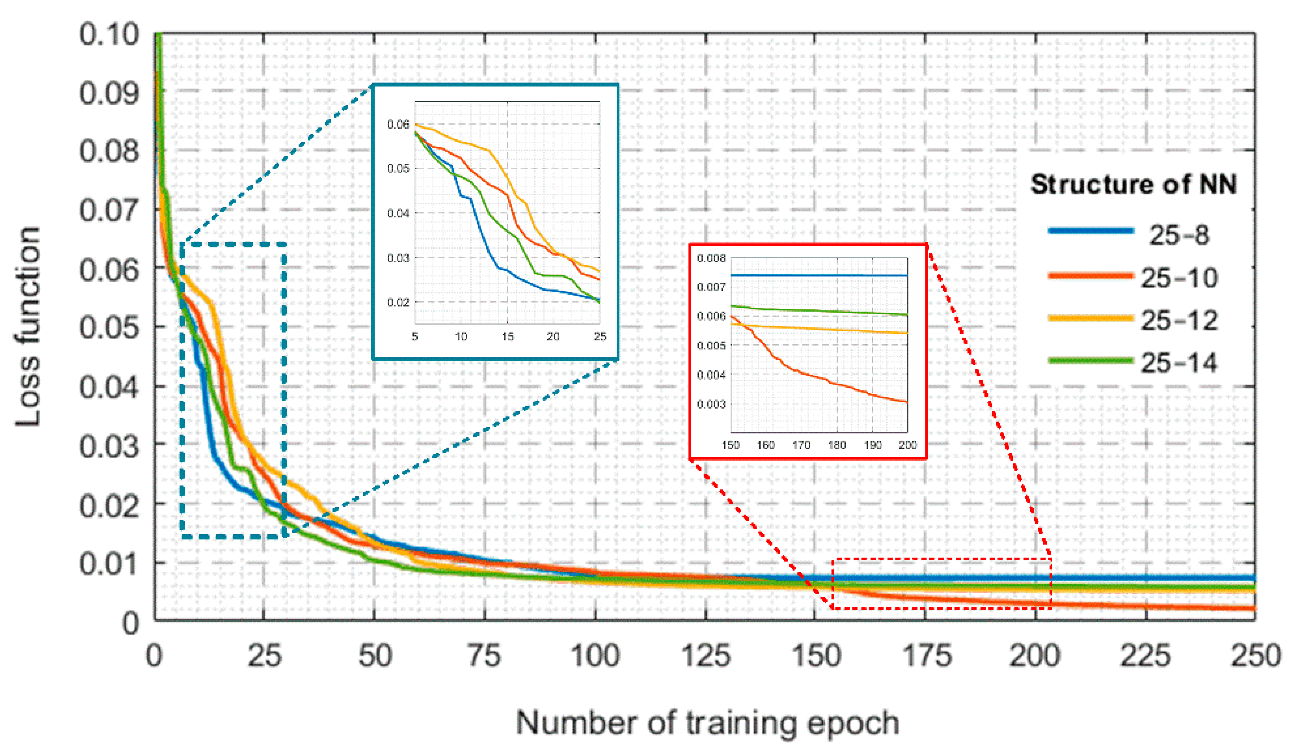
During this investigation, the structure of the MLP network with two hidden layers with 25 and 10 neurons, respectively, and the activation function was used in the form of a hyperbolic tangent. The output layer constitutes the softmax classifying function, which converts a vector into a probability distribution of possible outcomes. The structure of the network was chosen in such a way that there were 2N + 1 neurons in the first hidden layer, according to the MLP theory (where N means the number of elements in the input vector) [35]. In the second hidden layer, a number of 10 neurons was assumed (starting from the number of neurons larger than the size of the output vector size). Furthermore, to validate the proper selection of the structure, the learning curves were analyzed (Figure 9). The network training process based on the Levenberg–Marquardt (LM) algorithm was carried out for 600 teaching epochs, assuming an initial learning coefficient of 0.01.
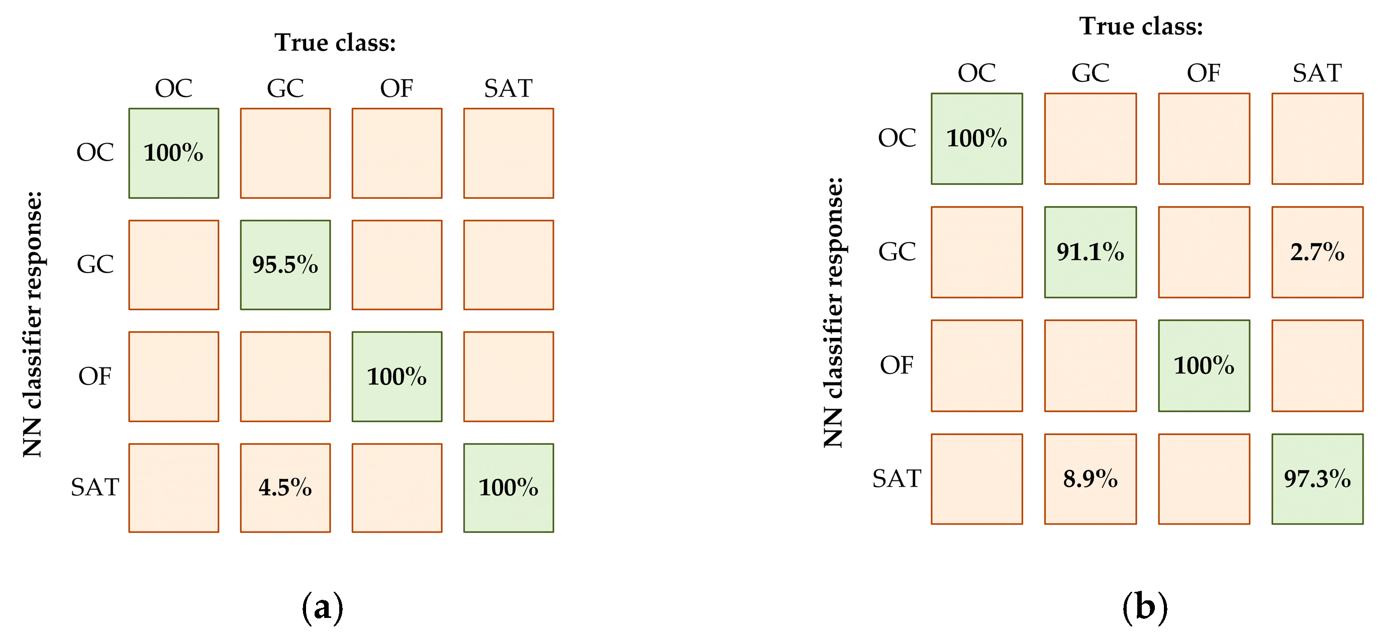
The analysis of the learning curves presented in Figure 9 clearly shows the correctness of selecting the MLP structure. The MLP with 25 and 10 neurons was characterized by the high dynamic of the training process as well as the lowest value of the loss function observed after 150 epochs. To present a clear comparison of the learning curves, the figure was limited to 250 epochs, while the entire training was carried out for 600 epochs. To verify the correctness of the training process and, in particular, the ability to assess the type of damage to CSs, network responses in the form of a confusion matrix were analyzed (Figure 10). The precision indices shown in the confusion matrices were calculated based on 224 cases for the eight categories of failures considered during various motor operating conditions.
The incorrect information that appears does not significantly affect the effectiveness of system classification, reaching 100%, except for gain change, which is 95.5% for the training data set (Figure 10a). The effectiveness of CS fault classification was estimated at 97.1% for the training data set.
The verification of the developed NN for the testing data (Figure 10b) was based on simulation data coming from five different rotor speed values (0.25ωmN, 0.30ωmN, 0.65ωmN, 0.75ωmN, 0.85ωmN) and for four different load torque values (0.2tLN, 0.4tLN, 0.6tLN, 0.8tLN). For these drive operating conditions, the reaction of the network was tested using an input vector containing 224 cases. It should be noted that the testing data were not used during the NN training.
The failure classifier verification was carried out in a manner analogous to that presented above for the training data. The analysis of the confusion matrix presented in Figure 10a confirms the very high precision of the CS fault classification system. Based on the network responsible for the test data set (Figure 10b), the classification efficiency was estimated at 98.9%. As in the case of responses to training data, the only erroneous MLP responses are observed between failure states: gain change (91.1%) and saturation fault (97.3%). Moreover, detailed analysis of NN responses allows us to observe that the MLP provides only correct information about the phase of CS damage (localization). The accuracy of the fault localization reached for the training and testing data sets was 100%.
The dependencies of the responses of the classification system on the actual technical condition of the CSs presented in Figure 10 indicate high MLP approximation abilities for the proposed input vector. In addition, it should be noted that errors that occur relate to the diagnosis of two types of damage: saturation and gain change. This fact results from a very similar influence of these damages on the signals of measured currents, making the classification process based on the analysis of consecutive samples of measured signals extremely difficult (Table 1, Equations f3 and f5). In the later stages of the investigation, the ability to detect and classify failures under the operation of the online drive system was verified.

5. Verification of NN-Based CS Fault Classifier in IM Drive System

In practical implementations, the operation of the CS failure detection and classification system is exposed to disturbances resulting from measurement noise, measurement system irregularities, or the impact of changes in machine operating conditions. The classification algorithm used in the investigation is based on the operation of a neural data approximator in the form of MLP, which, based on information about subsequent samples of measured signals, determines a given type of CS damage. Therefore, even single outlier samples may result in erroneous responses of the NN that do not reflect the actual technical condition of the CSs.
Due to the fact that the phase currents were analyzed by NN all the time (under on-line operation of the drive system), random disturbances appeared at its output, even in simulation tests (resulting from inverter supply of the IM). To eliminate them and improve the effectiveness of failure classification, it was decided to use the following algorithm. All tests were carried out for the IM drive modeled in MATLAB-Simulink, with the motor parameters presented in Appendix A (Table A1).
The authors developed a simple zero-crossing detection algorithm with an assumed hysteresis level. The algorithm is designed to detect the moment in time when the sign of the current changes. The simplest way is to compare the sign of the stator current and the previous measurement. Due to the current ripples near zero, an insensitive region (hysteresis level denoted by ith) was used, which is defined as follows:
i t h < i s < i t h
Zero crossing detection is indicated when the decreasing value of the measured current falls in the range ±ith. The current estimated by the VCS for phase A was monitored all the time. After the detection of the current signal crossing zero, the individual outputs of the network were individually summed up to the next zero crossing point. At the end of the half-period, the sums obtained were tested. The highest sum values for one of the analyzed MLP outputs mean that the type of CS damage assigned to this neuron occurs more frequently in the considered half-period. Due to the duration of the ratio of the saturation signal to the duration of the entire half-period, it was decided to amplify the Y4 output of the network responsible for this type of damage by multiplying it by the constant η value. In the simulations, the classification of the failure type started after the failure detection and its compensation by switching to the estimated current signals from VCS and lasted until the end of the simulation tests (purple line in the following figures).
The results of the classification of CS faults using the proposed MLP network are shown in Figure 11. The failures analyzed concern phase A (Figure 11a,c,e,g) and phase B (Figure 11b,d,f,h). The correct classification of the damage was carried out at the zero crossing of the estimated current in a given phase. During the simulation tests, the following fault scenarios for different motor speeds and loads and different CS faults were analyzed:
-
Complete loss of the current signal for 25% of the rated speed and 75% of the rated torque (Figure 11a,b);
-
Change of the CS gain equal to 1.35 for 75% of the rated speed and 25% of the rated torque (Figure 11c,d);
-
Constant component of the measured current (off-set) equal to 0.15 p.u. for 75% of the rated speed and 75% of the rated torque (Figure 11e,f);
-
Saturation at 0.34 p.u. for 25% of the rated speed and 75% of the rated torque (Figure 11g,h).
In order for the stator current waveforms and the operation of the neural fault classifier for the selected operating conditions of the drive to be legible, zooms were made on the timeline at intervals of ±0.05 s from the appearance of the simulated CS fault (t = 3 s) and its disappearance (t = 4 s).
As can be seen in the graphs, the NN correctly identified the selected types of CS damage regardless of the CS localization (stator current phase A or B). Due to the switch of the control structure to the stator currents estimated by VCS, failure symptoms can be identified more easily. Moreover, a detailed analysis of the simulation result showed that the CS fault in one of the phases does not affect the operation of the control structure. However, it should be noted that the classification time depends on the rotational speed of the IM and the sampling frequency. This fact results from the algorithm based on signal samples, and what is most important is the dependence of the classifier output information on the period of phase current signals. However, the proposed NN-based CS fault classification system can be successfully implemented in AC drive systems. It should be noted that the proposed method can be easily extended to detect damage to more than one sensor. This can be achieved by providing the appropriate training data for the designed MLP network.
Research was carried out on a simulation model of the IM drive. In future studies, the proposed classifier will be verified on the real object, also for multiple sensor faults and used to select the damage compensation method according to the idea of FTC.

6. Conclusions

The results of the investigations presented in this article allow us to conclude that the proposed neural fault classifier (NN-FC) of different CS failures is capable of differentiating the selected CS faults in real time. It is characterized by high effectiveness as well as a short reaction time to the damage that occurred. The results of tests during the online operation of the DRFOC drive system confirm that the fault classification time is similar for CS damages in phases A and B. The longest classification time was observed in the case of saturation fault. The time is then dependent on the actual operating frequency of the drive and should not be more than 1.5 current periods. However, it should be emphasized that due to the proposed three-stage FTC strategy, during the time dedicated to fault classification, the previously detected CS fault has been compensated by switching the control structure to the stator currents estimated by VCS, so it does not adversely affect the quality of the entire drive system operation. It should also be highlighted that the applied concept of the FTC system consists of the use of VSC not only at the stage of damage detection but also to compensate for the detected failure in any stator phase and ensure uninterrupted operation of the vector-controlled structure. This, in turn, made it possible to classify the type of damage using the proposed neural classifier during post-fault operation of the drive.
Moreover, due to such an accurate classification of the CS failures analyzed, the proposed solution allows the extension of the FTC system with methods to compensate for a detected type of damage. It should be noted that the proposed method can be easily extended to detect damage to more than one sensor. This can be achieved by providing the appropriate extended training data for the designed MLP network.
The advantage of the MLP network used in the study is the easy mathematical description which allows for the practical implementation of the proposed method, using generally available (low-cost) industrial processors (e.g., ARM). Future research will be connected with the experimental test of the MLP-based CS fault classification developed in the proposed FTC strategy also for multiple CS faults.

Author Contributions

All the authors contributed equally to the concept of the paper and proposed the methodology; investigation and formal analyses, M.S., K.T., M.A. and T.O.-K.; software and data curation, K.T. and M.A.; measurements, K.T. and M.S.; writing—original draft preparation, M.A., K.T. and M.S.; writing—review and editing, T.O.-K. and M.S.; supervision, project administration and funding acquisition, T.O.-K. All authors have read and agreed to the published version of the manuscript.

Funding

This work was supported by the National Science Centre Poland under grant number 2021/41/B/ST7/02971.

Institutional Review Board Statement

Not applicable.

Informed Consent Statement

Not applicable.

Data Availability Statement

Not applicable.

Conflicts of Interest

The authors declare no conflict of interest.

Nomenclature

All state variables and parameters are expressed in per unit system (p.u.).
State variables:
us spatial vector of stator voltage
is, ir spatial vectors of stator and rotor currents
Ψs, Ψr spatial vectors of stator and rotor fluxes
tem, tL electromagnetic and load torques
ωm angular rotor speed
ωs ψ angular synchronous speed of the rotor flux spatial vector
γψ angle between rotor flux vector and axis A of the stator winding
dABC duty cycles values
SABC logic states of the VSI switches
Parameters:
rs, rr stator and rotor windings resistances
lσs, lσr, lm stator and rotor leakage inductances and main inductance
TM mechanical time constant
fsN nominal stator frequency
Coordinate systems:
(A-B-C) three-phase frame
(α-β) stationary reference frame
(x-y) synchronously rotating reference frame (with rotor flux angular speed, ω)
Indexes:
refreference value
eestimated value
Abbreviations
CS current sensor
DRFOC direct rotor flux oriented control
FC fault compensation
FD fault detection
FTC fault-tolerant control
IM induction motor
MLP multilayer perceptron
NN neural network
NN-FC neural network-based fault classifier
PI PI controller
SVM space vector modulation
VSI voltage source inverter
VT vector transform

Appendix A

Table A1. Induction motor parameters.
Symbol(ph.u.)(p.u.)
Rated phase voltage, UN230 V0.707
Rated phase current, IN2.5 A0.707
Rated power, PN1.1 kW0.638
Rated speed, nN1390 rpm0.927
Rated torque, TeN7.56 Nm0.688
Number of pole pairs, pb2-
Rotor winding resistance, Rr4.968 Ω0.0540
Stator winding resistance, Rs5.114 Ω0.0556
Rotor leakage inductance, Lσr31.6 mH0.1079
Stator leakage inductance, Lσs31.6 mH0.1079
Main inductance, Lm541.7 mH1.8498
Rated rotor flux, ΨrN0.7441 Wb0.7187
Mechanical time constant, TM0.25 s-

References

  1. Isermann, R. Fault-Diagnosis Applications, Model-Based Condition Monitoring: Actuators, Drives, Machinery, Plants, Sensors, and Fault-Tolerant Systems; Springer: Berlin/Heidelberg, Germany, 2011. [Google Scholar]
  2. Isermann, R. Fault-Diagnosis Systems: An Introduction from Fault Detection to Fault Tolerance; Springer: Berlin, Germany, 2006. [Google Scholar]
  3. Muenchhof, M.; Beck, M.; Isermann, R. Fault-tolerant actuators and drives—Structures, fault detection principles and applications. Annu. Rev. Control. 2009, 33, 136–148. [Google Scholar] [CrossRef]
  4. Orlowska-Kowalska, T.; Wolkiewicz, M.; Pietrzak, P.; Skowron, M.; Ewert, P.; Tarchala, G.; Krzysztofiak, M.; Kowalski, C.T. Fault Diagnosis and Fault-Tolerant Control of PMSM Drives–State of the Art and Future Challenges. IEEE Access. 2022, 10, 59979–60024. [Google Scholar] [CrossRef]
  5. Dybkowski, M.; Klimkowski, K.; Orlowska-Kowalska, T. Speed and Current Sensor Fault-Tolerant-Control of the Induction Motor Drive. In Advanced Control of Electrical Drives and Power Electronic Converters; Kabzinski, J., Ed.; Springer: Berlin/Heidelberg, Germany, 2017; pp. 141–167. [Google Scholar]
  6. Dybkowski, M.; Klimkowski, K. Stator current sensor fault detection and isolation for vector controlled induction motor drive. In Proceedings of the IEEE International Power Electronics and Motion Control Conference (PEMC), Varna, Bulgaria, 25–28 September 2016; pp. 1097–1102. [Google Scholar]
  7. Ha, J.I. Current prediction in vector-controlled PWM inverters using single DC-Link current sensor. IEEE Trans. Ind. Electron. 2010, 57, 716–726. [Google Scholar]
  8. Kim, H.R.; Jahns, T.M. Current control for AC motor drives using a single dc-link current sensor and measurement voltage vectors. IEEE Trans. Ind. Appl. 2006, 42, 1539–1547. [Google Scholar] [CrossRef]
  9. Salmasi, F.R.; Najafabadi, T.A. An adaptive observer with online rotor and stator resistance estimation for induction motors with one phase current sensor. IEEE Trans. Energy Convers. 2011, 26, 959–966. [Google Scholar] [CrossRef]
  10. Najafabadi, T.A.; Salmasi, F.R.; Maralani, P.J. Detection and isolation of speed-, dc-link voltage-, and current-sensor faults based on an adaptive observer in induction-motor drives. IEEE Trans. Ind. Electron. 2011, 58, 1662–1672. [Google Scholar] [CrossRef]
  11. Romero, M.E.; Seron, M.M.; Dona, J.A.D. Sensor fault-tolerant vector control of induction motors. IET Control Theory Appl. 2010, 4, 1707–1724. [Google Scholar] [CrossRef]
  12. Azzoug, Y.; Sahraoui, M.; Pusca, R.; Ameid, T.; Romary, R.; Cardoso, A.J.M. Current sensors fault detection and tolerant control strategy for three-phase induction motor drives. Electr. Eng. 2021, 103, 881–898. [Google Scholar] [CrossRef]
  13. Adamczyk, M.; Orlowska-Kowalska, T. Current Sensors Fault Detection and Tolerant Control for Induction Motor Drive. In Proceedings of the IEEE 19th International Power Electronics and Motion Control Conference, PEMC 2021, Gliwice, Poland, 25–29 April 2021. [Google Scholar]
  14. Salmasi, F.R. A self-healing induction motor drive with model free sensor tampering and sensor fault detection, isolation, and compensation. IEEE Trans. Ind. Electron. 2017, 64, 6105–6115. [Google Scholar] [CrossRef]
  15. Yu, Y.; Zhao, Y.; Wang, B.; Huang, X.; Xu, D. Current Sensor Fault Diagnosis and Tolerant Control for VSI-Based Induction Motor Drives. IEEE Trans. Power Electron. 2018, 33, 4238–4248. [Google Scholar] [CrossRef]
  16. Tabbache, B.; Rizoug, N.; Benbouzid, M.E.H.; Kheloui, A. A control reconfiguration strategy for post-sensor FTC in induction motor based EVs. IEEE Trans. Veh. Technol. 2013, 62, 965–971. [Google Scholar] [CrossRef] [Green Version]
  17. Jankowska, K.; Dybkowski, M. A Current Sensor Fault Tolerant Control Strategy for PMSM Drive Systems Based on Cri Markers. Energies 2021, 14, 3443. [Google Scholar] [CrossRef]
  18. Jankowska, K.; Dybkowski, M. Design and Analysis of Current Sensor Fault Detection Mechanisms for PMSM Drives Based on Neural Networks. Designs 2022, 6, 18. [Google Scholar] [CrossRef]
  19. Adouni, A.; Hamed, M.B.; Flah, A.; Sbita, L. Sensor and actuator fault detection and isolation based on artificial neural networks and fuzzy logic applicated on Induction motor. In Proceedings of the International Conference on Control, Decision and Information Technologies CoDIT, Hammamet, Tunisia, 6–8 May 2013. [Google Scholar]
  20. Jäger, G.; Zug, S.; Brade, T.; Dietrich, A.; Steup, C.; Moewes, C.; Cretu, A.M. Assessing neural networks for sensor fault detection. In Proceedings of the 2014 IEEE International Conference on Computational Intelligence and Virtual Environments for Measurement Systems and Applications (CIVEMSA), Ottawa, ON, Canada, 5–7 May 2014; pp. 70–75. [Google Scholar]
  21. Dybkowski, M.; Klimkowski, K. Artificial Neural Network Application for Current Sensors Fault Detection in the Vector Controlled Induction Motor Drive. Sensors 2019, 19, 571. [Google Scholar] [CrossRef] [PubMed]
  22. Gou, B.; Xu, Y.; Xia, Y.; Wilson, G.; Liu, S. An Intelligent Time-Adaptive Data-Driven Method for Sensor Fault Diagnosis in Induction Motor Drive System. IEEE Trans. Ind. Electron. 2019, 66, 9817–9827. [Google Scholar] [CrossRef]
  23. Manohar, M.; Das, S. Current sensor fault-tolerant control for direct torque control of induction motor drive using flux linkage observer. IEEE Trans. Ind. Informat. 2017, 13, 2824–2833. [Google Scholar] [CrossRef]
  24. Adamczyk, M.; Orlowska-Kowalska, T. Virtual Current Sensor in the Fault-Tolerant Field-Oriented Control Structure of an Induction Motor Drive. Sensors 2019, 19, 4979. [Google Scholar] [CrossRef]
  25. Adamczyk, M.; Orlowska-Kowalska, T. Postfault Direct Field-Oriented Control of Induction Motor Drive using Adaptive Virtual Current Sensor. IEEE Trans. Ind. Electron. 2022, 69, 3418–3427. [Google Scholar] [CrossRef]
  26. Adamczyk, M.; Orlowska-Kowalska, T. Influence of the stator current reconstruction method on direct torque control of induction motor drive in current sensor postfault operation. Bull. Pol. Acad. Sci. Tech. Sci. 2022, 70, e140099. [Google Scholar]
  27. Azzoug, Y.; Pusca, R.; Sahraoui, M.; Ammar, A.; Ameid, T.; Romary, R.; Cardoso, A.J.M. An Active Fault-Tolerant Control Strategy for Current Sensors Failure for Induction Motor Drives Using a Single Observer for Currents Estimation and Axes Transformation. Eur. J. Electr. Eng. 2021, 23, 467–474. [Google Scholar] [CrossRef]
  28. Adamczyk, M.; Orlowska-Kowalska, T. Self-Correcting Virtual Current Sensor Based on the Modified Luenberger Observer for Fault-Tolerant Induction Motor Drive. Energies 2021, 14, 6767. [Google Scholar] [CrossRef]
  29. Chakraborty, C.; Verma, V. Speed and current sensor fault detection and isolation technique for induction motor drive using axes transformation. IEEE Trans. Ind. Electron. 2014, 62, 1943–1954. [Google Scholar] [CrossRef]
  30. Wang, W.; Feng, Y.; Shi, Y.; Cheng, M. Fault-tolerant control of primary permanent-magnet linear motors with single phase current sensor for subway applications. IEEE Trans. Power Electron. 2019, 34, 10546–10556. [Google Scholar] [CrossRef]
  31. Orlowska-Kowalska, T. Sensoless Induction Motor Drives; Wroclaw University of Technology Press: Wroclaw, Poland, 2003. [Google Scholar]
  32. Kazmierkowski, M.P.; Krishnan, R.; Blaabjerg, F. Control in Power Electronics-Selected Problems; Academic Press: Cambridge, MA, USA, 2002. [Google Scholar]
  33. Lee, K.S.; Ryu, J.S. Instrument fault detection and compensation scheme for direct torque controlled induction motor drives. IEE Proc. Control Theory Appl. 2003, 150, 376–382. [Google Scholar] [CrossRef]
  34. Adamczyk, M. Rotor resistance estimator based on virtual current sensor algorithm for induction motor drives. Power Electron. Drives 2020, 5, 143–156. [Google Scholar] [CrossRef]
  35. Bishop, M.C. Neural Networks for Pattern Recognition, 1st ed.; Oxford University Press: New York, NY, USA, 1996. [Google Scholar]
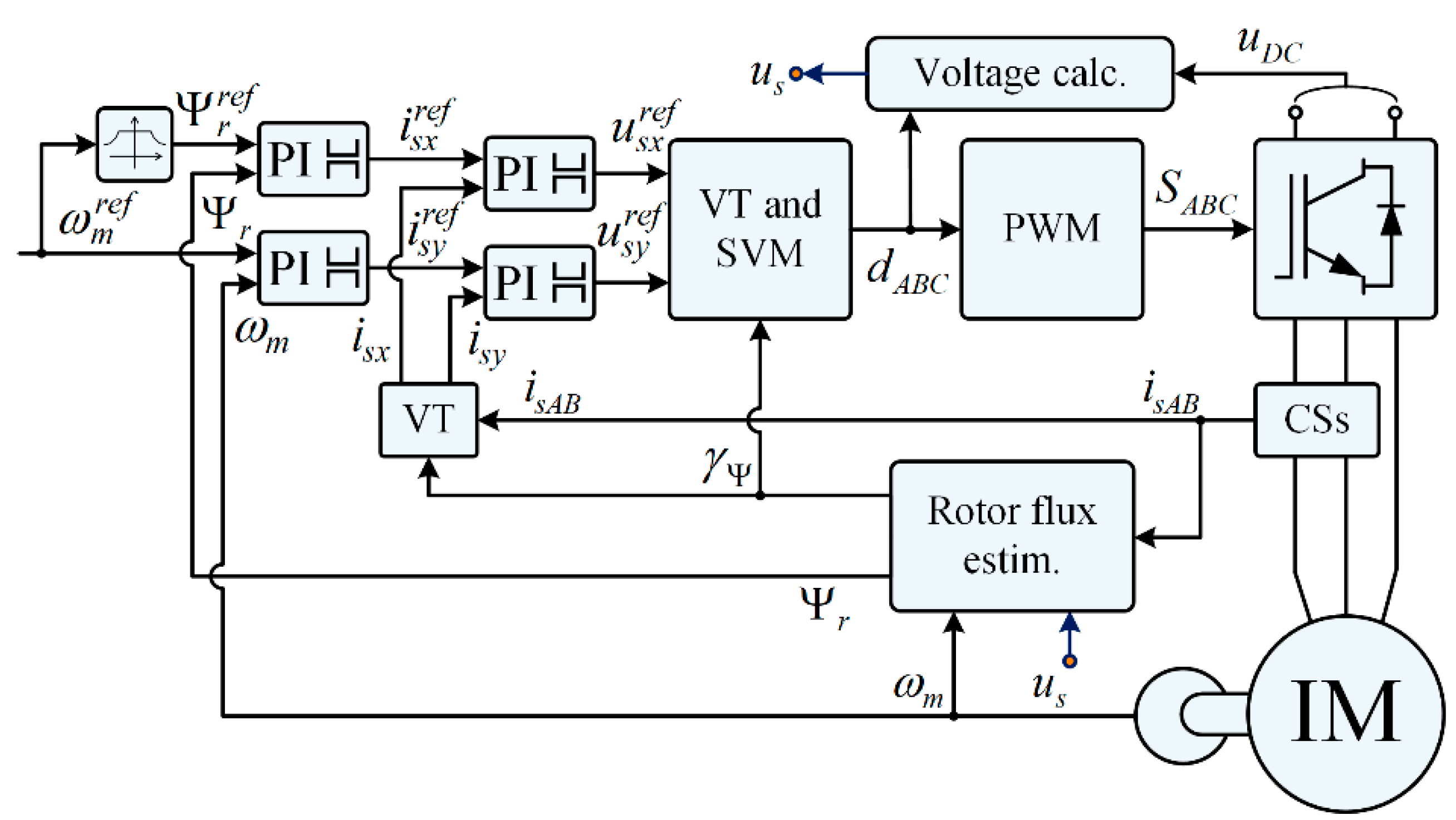
Figure 1. Schematic diagram of classic DRFOC structure.
Energies 15 06646 g001
Figure 2. Example of the LEM-type transducer.
Energies 15 06646 g002
Figure 3. Types of CS faults: open circuit (a), disconnections (b), gain change (c), offset (d), saturation (e), noise (f).
Energies 15 06646 g003
Figure 4. Waveforms of rotor speed (a,d), electromagnetic torque (b,e) and rotor flux (c,f), under open circuit fault (ac) and CS saturation (df) in phase A.
Energies 15 06646 g004
Figure 5. FTC three-stage strategy.
Energies 15 06646 g005
Figure 6. Scheme of the VCS algorithm.
Energies 15 06646 g006
Figure 7. Scheme of the fault detection and compensation algorithm.
Energies 15 06646 g007
Figure 8. Scheme of DRFOC structure with CS-FTC algorithm and NN classifier.
Energies 15 06646 g008
Figure 9. Training process of the multilayer perceptron—learning curves.
Energies 15 06646 g009
Figure 10. Verification of the MLP-based CS fault classifier—confusion matrices: training data set (a), testing data set (b); OC—signal loss, GC—gain change, OF—offset, SAT—saturation, ωm = 0 − ωN, tL = 0 − tLN.
Energies 15 06646 g010
Figure 11. Verification of the proposed CS fault classifier in the IM drive system: (a,b) signal loss: ωm = 0.25ωN, tL = 0.75tLN; (c,d) gain change: ωm = 0.75ωN, tL = 0.25tLN; (e,f) off-set: ωm = 0.75ωN, tL = 0.75tLN; (g,h) saturation: ωm = 0.25ωN, tL = 0.75tLN.
Energies 15 06646 g011
Table 1. Types of CS faults.
Fault NoFault TypeMathematical Description of CS Fault
f1Open circuit0
f2Disconnections [ 0 I m sin ( ω t ) ]
f3Gain change ε I m sin ( ω t )
f4Offset I m sin ( ω t ) + I o f f s e t
f5Saturation { I s a t for I m sin ( ω t ) I s a t I m sin ( ω t ) for | I m sin ( ω t ) | < I s a t I s a t for I m sin ( ω t ) I s a t
f6Noise I m sin ( ω t ) + n ( t )
where: Im—amplitude of the phase stator current, ω—pulsation.
Publisher’s Note: MDPI stays neutral with regard to jurisdictional claims in published maps and institutional affiliations.