Review

Evaluating Performance Indices of Electrostatic Precipitators

by
Mohamed Badran
* and
Abdallah Mahmoud Mansour
Department of Mechanical Engineering, The American University in Cairo, New Cairo 11835, Egypt
*
Author to whom correspondence should be addressed.
Energies 2022, 15(18), 6647; https://doi.org/10.3390/en15186647
Submission received: 21 June 2022 / Revised: 4 September 2022 / Accepted: 5 September 2022 / Published: 11 September 2022

Abstract

:
Utilizing electrostatic precipitators (ESPs) is an efficient particle removal method that sees a wide usage in industrial environments. This is mainly because of the low drop of the pressure flow, while retaining high collection efficiency, alongside being cost-effective. This paper reviewed previous works concerning optimizing the performance of single- and multi-stage ESPs by changing several design parameters and evaluating the effects on different performance indices, such as the corona power ratio, current-voltage characteristics, and overall collection efficiency. The review then goes through several modelling methodologies, showcasing their shortcomings and developments, as well as the relationship between the electrohydrodynamic (EHD) flow and the precipitation performance. The performance effects of using different electrode configurations and designs in terms of the number of electrodes, relative dimensions, spacings, channel lengths, and overall design were also reviewed.

1. Introduction

Electrostatic precipitators (ESPs), which cover a wide range on the spectrum of particles (0.01–1000 μm), are commonly used in the industry, especially as the atmosphere particle emission environmental regulations are consistently getting tighter and interest in the filtration of fine particle removal is at all-time high.
Electrostatic precipitators are a class of particle removal devices mainly used to remove particulate matter from a flowing gas. This process is conducted by utilizing an electrical field to ionize and transport the flow particles. This is in contrast to traditional methods that use, as an example, mechanical filtration. The working concept behind ESPs, however, is not new at all.
At around 600 B.C., the experimental fact that fibers can be attracted to a piece of amber after being rubbed was discovered by the Greeks. The characteristics of this force was later researched by Coulomb in the 18th century [1]. During 1600, the first observation directly related to ESPs was expressed by William Gilbert [2].
Hohlfeld experimented with precipitating fog inside with an electrified point in 1824. The first industrial attempt was performed in the 1880s, and it is attributed to Professor O. Lodge and Mr. J. Clark of Liverpool University [2].
This paper gives a brief background on the main ESP classification, alongside with the ESP working principles. It then discusses methods of assessing their performance and how each change in the geometric parameters affects this performance. Then, a summary of notable works that evaluate ESP performance is presented.

2. ESP Background

Electrostatic precipitators can be arranged based on their number of stages or by the geometric configuration of their collection plates. Both classifications are discussed in this section. The working principle of ESPs is also introduced.

2.1. ESP Classification: Collecting Electrodes Configuration

Electrostatic precipitators can be classified according to different criterion, such as the configuration of the collecting electrode or the number of stages [3]. Regardless of the chosen classification method, the key working principles of ESPs are consistent.
The configuration of the collecting electrodes can vary greatly from one ESP to another. Perhaps the most common is the wire-plate type, shown in Figure 1, which consists of flat parallel collection plates surrounding the emitting electrodes responsible for initiating the corona discharge. For this reason, these are also called the discharge electrodes. The radius of the emitting wire, rw, and the wire-to-wire spacing, s, are specified in this instance.
For both the wire-plate and transverse plate types, Wp and Lp are the main dimensions used to identify the width and length of the collection plate, respectively, while the plate-to-plate distance is designated by d. Transverse plate ESPs, shown in Figure 2, are another common type that, similar to the aforementioned wire-plate type ESP, rely on parallel collecting plates. However, these plates are arranged in a transverse configuration relative to the gas flow direction.
As for the wire-cylinder type ESP, defining the critical dimensions can aid with understanding the overall footprint of the ESP. These dimensions, also given in Figure 2, include the radius of the cylindrical collection plate, R, as well as the length of the emitting electrode.

2.2. ESP Classification: Number of Stages

The main advantage of single-stage ESPs is that they are less susceptible to particle re-entrainment compared to muti-stage ESPs. However, multi-stage ESPs generally have a larger collecting electrode surface area for the collection stage as a result of space reduction between the collecting electrodes, as well as dedicating a separate section for the particle collection [3] without sacrificing the more-compact footprint when compared to a single-stage ESP. The separation of charging and collection stages has other advantages in terms of improving the precipitation efficiency and the resiliency against variable inlet flow velocity [4,5], as well as aiding with corrosion resistance [6]. An HVDC power supply is used to power both the charging stage as well as the collection stage (with a polarity that is opposite to the charging stage), as shown in Figure 3, where flue gas flows by the charging stage first, followed by the collection stage.

2.3. Working Principle

The setup of an ESP consists of one or more discharge electrodes (thin wires) and a collecting electrode (cylindrical/flat plate). Its working principle can be understood by looking at the basic phenomena happening during particle collection: corona discharge, particle ionization, and particle transport. These steps are shown in Figure 4.
At the beginning, a high-voltage DC source, usually of a negative polarity, supplies discharge wires with power until a specific electric field value (threshold value) is achieved. As a result, corona discharge occurs (Figure 4b). The gas in regions close to discharge electrodes is then ionized as a result. The resulting ions are then attached to the flow particles (Figure 4c). The charging process consists of a diffusion charging region for particles <0.1 μm and a field charging region for particles >1 μm. In practice, however, particles experience both simultaneously [2].
Finally, these particles migrate to the collecting electrodes of an opposite polarity (Figure 4d). When the charged particles land on the collecting electrodes, ions must flow into them, passing through the dust layer and contributing to the importance of particle resistivity in ESP operation. The collected particles are then collected by either vibrating the collection plates, or ‘rapping’, or by washing the plates off with water. Dislodging the particles can also be performed by scraping the collection place. The collection process is necessary as already-collected particles can be re-entrained into the gas flow again, negatively impacting the collection efficiency [2].

3. Collection Efficiency and Performance Assessment Methods of an ESP

The performance of an ESP can be evaluated by assessing several parameters. Economically, a corona power ratio can give a general idea of the power consumption relative to the overall capacity of an ESP. An assessment of the current-voltage characteristics and the collection efficiency can also be used to determine the ESP performance.

3.1. Current-Voltage Characteristics

Another method of assessing the ESP performance is comparing the effect of changing geometric parameters on the resulting corona current-voltage (I–V) characteristics of an ESP [7,8,9,10,11,12,13]. This method involves measuring the value of the corona discharge at each voltage value, where higher corona current values imply more deposition. The corona discharge, however, is not linearly dependent on the applied voltage alone, with ion mobility playing an important role in affecting the amount of corona discharge [10,14]. Other parameters, including electrode designs and their respective layout, can also affect the corona discharge. Verifying numerical ESP models is another common use case for I–V characteristics through direct comparison at different geometries, as shown in Figure 5 both numerically [11] and experimentally [9]. It can also be seen that varying the number of discharge electrodes has a pronounced effect on I–V characteristics. The same holds true for other geometric parameters as well.

3.2. Corona Power Ratio

Power consumption can give a better understanding of an electrostatic precipitator from an economical point of view [15]. The corona power ratio, Pc (W·s/m3), is commonly used when evaluating the power consumption in a practical environment. It can be defined as the ratio of the total power consumed (P = IV) to the overall gas flow rate, Q [16].
P c = P / Q

3.3. Modelling Approaches of Collection Efficiency

The precipitation performance for a gas cleaning device can be evaluated simply by comparing the ratio of the precipitated dust mass concentration to the input dust mass concentration (general method) [7,17]. This ratio is known as the collection efficiency ( η ) , and can be evaluated as follows:
η = 1 m o u t m i n
where mout is the mass concentration of the precipitated dust, and min is the mass concentration of the input dust. It can also be expressed with the ratio between precipitated dust concentration Co and the input dust concentration Ci [18,19].
η = c o c i

3.3.1. Deutsch Method

A more-common method for assessing ESP efficiency is the Deutsch-Anderson model [7,20], expressed by:
η = 1 e x p ( A Q ω d )
where Q is the total processed gases flow rate, and A is the precipitator’s collection area. ωd is the effective particle drift velocity, and it can be estimated with [21]:
ω d = q p | E | C u 3 π μ d p
where qp is the charge of the particle, | E | is the magnitude of the electric field, Cu is the Cunningham slip factor, μ is the gas viscosity, and dp is the particle diameter. The drift velocity constant, ωd, can also be estimated with:
ω d = r E 0 E p 2 π μ
where r is the particle radius, and E0 and Ep are charging and precipitating fields, respectively. The main source of discrepancies between the Deutsch method and experimental results exists mainly due to allowing for complete mixing in planer slices transverse to the main direction flow, as proposed by this model, neglecting axial diffusion. The result is that the calculated effective migration velocity is 10% to 50% of the theoretical value [22].

3.3.2. Matts-Ohnfeldt Method

Another method is the Matts-Ohnfeldt formula, which is a modification of Deutsch’s general formula. This version allows the effective migration velocity (ωk) to become constant in relation to the total precipitation area [19]:
η = 1 e x p ( A Q ω k ) k
where k is dependent on the material collected from the flue gas. Finally, Peterson’s formula is based on the Stearn Catalytic model, where b is a collected material-dependent parameter, such as k. In the case of coal ash, for instance, k and b take values of 0.5 and 0.24, respectively. Here, ωb is the migration velocity as well [19]:
η = 1 ( 1 b A Q ω b ) 1 b

3.3.3. Cooperman Method

The Cooperman efficiency can be given by:
η = 1 e x p ( A Q ω d )
Compared to the Deutsch method, the main change is that Cooperman’s method correlates the precipitation efficiency with flow turbulence [23]. This method also takes into account the effective migration velocity without any special assumptions [23].

3.3.4. Zhibin and Guoquan Method

Precipitation efficiency in the Zhibin and Guoquan method is given by:
η = 1 v π   E y   L   0 d 2 e x p ( v ( y w v L ) 2 4   E y   L )   d y
where v is the gas velocity, d 2 is the discharge electrode-to-plate spacing, L is the channel length, Ey is the diffusion coefficient, and w is the theoretical migration velocity. The main advantage that this model has is that, when evaluating the particle transport, it considers the effects of electrostatic force [22]. It also takes turbulent diffusion into account, denoted with the coefficient Ey, which can be indirectly determined from a detailed measurement of the flow with:
E y = 1 8 C f v d S c
where v is the gas velocity, d is the plate-to-plate distance, and Sc is turbulent Schmidt number. Sc is given by [24], where RE is Reynolds number:
S c = 0.74   R E 0.04

3.3.5. Considerations for Transverse-Plate Type ESP

Note that the collection efficiency only applies to a certain particle diameter [8]. This is apparent when evaluating efficiency using the following method:
η = 1 c d , o u t l e t c d , i n l e t
where cd,outlet and cd,inlet are the outlet and inlet particles’ concentrations, respectively, with diameter d. This term is known as grade efficiency, which is a key parameter for evaluating the performance of an ESP [21].
In the case of transverse-plate type ESPs, the inertial forces need to be taken into consideration. If that is the case, the total combined efficiency, η t , is given by [25]:
η t = 1 ( 1 η e ) ( 1 η i )
where ηe is concerned with the current and voltage effect on the overall collection efficiency, and it is given by:
η e = V n I
Here, n is an empirical constant. V and I are the applied voltage and current, respectively.
ηi is the inertial particle classifier’s collection efficiency, where SSt is Stoke’s number [25]:
η t = f   ( S S t )
The methods discussed so far focus on particle collection efficiency, or effective consumption of electrical power [15]. Other parameters can be considered when assessing the performance of an ESP, depending on the specific needs of each application. Notable examples include electrical characteristics [7,8,9,10,26], electrohydrodynamic (EHD) flow characteristics [27,28,29,30,31], re-entrainment minimization [4,32], initial installation cost [33], and size constraints.

3.4. Material Considerations

In addition to power consumption, which is evaluated using the corona power ratio, industrial applications require special consideration for parameters such as discharge and collecting electrode materials [6,34,35]. Exploring alternative materials can be beneficial for corrosion-resistance by either using non-metallic materials or by applying special coatings. The electrical characteristics and precipitation performance of such precipitators are often compared with traditional precipitators. Such materials are usually polymeric, such as carbon-coated plastic (CPC), plastic-coated carbon (PCP) [6], and polyethylene terephthalate (PET) films [36].

4. Factors That Impact the Precipitation Performance

The performance of an electrostatic precipitator basically depends on several factors that can be categorized into geometry-dependent, flue gas-dependent, or power-dependent. This section starts by discussing the optimization of geometrical parameters, then moves to the effects of gas-flow velocity, and finally, the applied power variation is discussed both directly and by altering the number of emitting electrodes. A summary of works evaluating ESP designs is presented as a table at the end of this section. The summary shows the general layout and the design parameters of both numerical models and experimental ESPs.

4.1. Optmization of Geometrical Parameters

Optimizing the design and layout of both emitting and collection electrodes inside an ESP is the main factor affecting the voltage-current curve, a major ESP performance determinant when the temperature, pressure, and dust properties are constant [37]. Many of the reviewed research compared the performance of industrial plants and experimental setups [6,14,34,35,38,39,40,41,42] with numerical simulations, and good agreements often exist. It is worth mentioning, however, that the optimum design parameters are extremely sensitive depending on the surrounding environment and the specific application.
The effects of changing the diameter and the geometry of the discharge wires, as well as the wire-to-wire spacing, will be discussed, in addition to the negative influence of eccentric discharge wires in the wire-cylinder type ESPs. Similar parameters are of interest for the collecting electrodes, in the form of their geometry and spacing. Finally, changing the pre-charger stage length to collection stage length ratio effects will be evaluated for different particles.

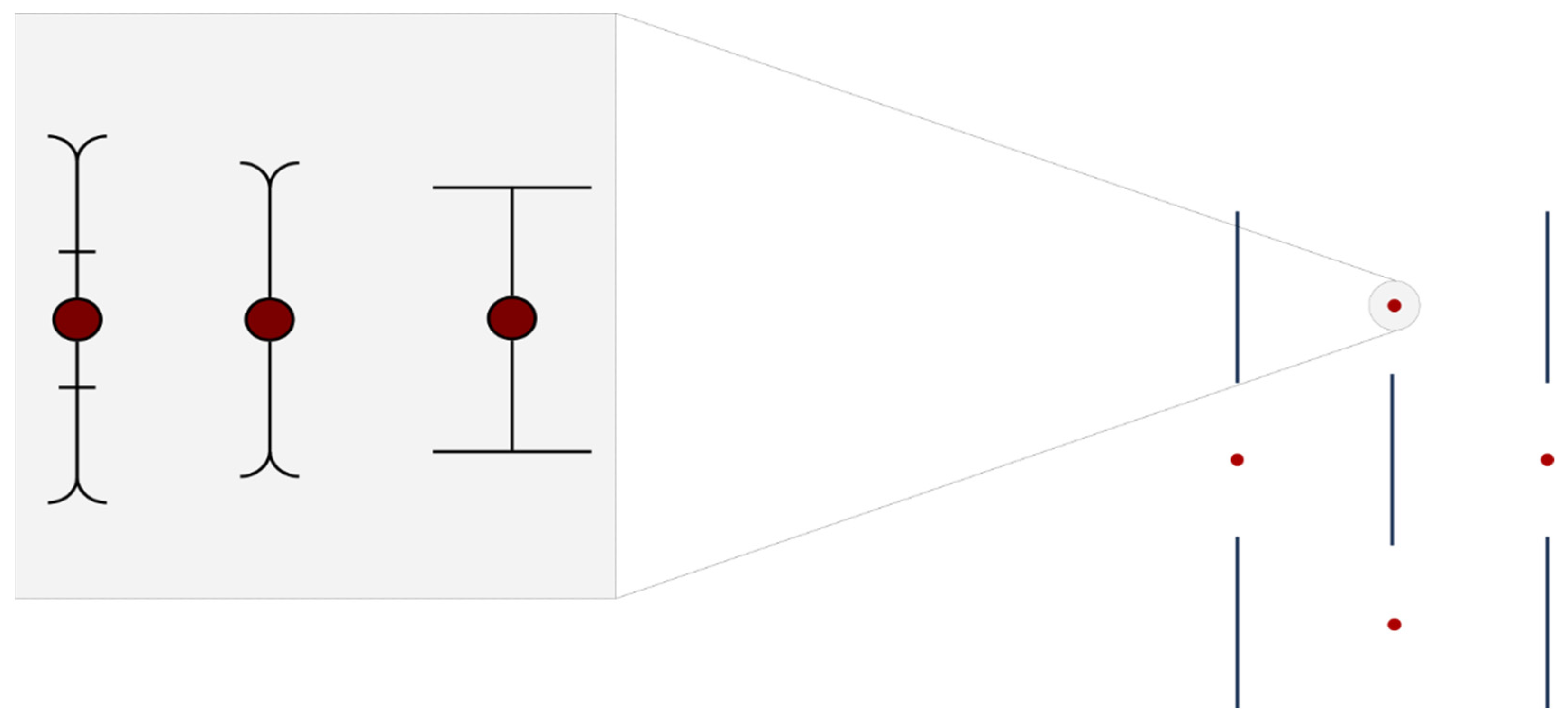
4.1.1. Discharge Electrode Geometry

Many efforts in optimizing the performance of single-stage ESPs focus on optimizing the geometry of critical components of an ESP. For instance, much of the work conducted investigated the effect of changing the emitting electrode geometry on performance and, more specifically, the effects that the barbed wires have.
For instance, as early as 1960, Lagarias [43] investigated different emitting electrode shapes, including square wire, cylindrical wire with spaced disks, and barbed wire, which were then compared. The findings confirmed that using barbed wires for the emitting electrode greatly increases the ESP’s collection efficiency, compared to that of one with a more-traditional smooth cylinder wire. The spacing between the barbs was found to be an important parameter in the collection efficiency as well. As such, the barbed and spiked discharge electrodes are some of the most researched topics in regard to optimizing the geometry for collection efficiency [14,19,37,43,44,45,46,47,48,49,50,51,52,53,54]. Some examples of these wires are shown in Figure 6. Similar designs are often used for discharge electrodes instead of the smooth wire-type discharge electrodes.
Other experimental works on barbed electrode wires investigated the barb length influence on the fractional efficiency of the ESP in two cases: constant voltage and constant electric power. It was determined that higher currents were yielded with longer barbs in the constant voltage case, making them the better choice in this case. However, when comparing lengths at constant electric power, the shorter barb configuration was superior. This happens because the lower current effect is mitigated by the fact that a higher electric field is generated because of the higher used voltage [37].
Changing the tip of the barb of a wire (or the needle geometry) can influence both the voltage-current characteristics, as well as the distribution of the current density [49]. More specifically, sharper tips yield a weaker onset field strength and more current compared to another that is blunter (less sharp).
Another factor that influences the fractional efficiency is the number of barbs and the spacing between them. It was found that, while the number of barbs increases the efficiency, this is only true to a certain point. This is the case because the electric field will eventually be homogenous, reducing its strength at the surface of the barb [37].
Other researchers have compared some unconventional emitting wire geometry, notably for industrial applications. Examples of these include star-shaped rods, saw-tooth spikes, and tubular spikes [38,55]. It is worth noting, however, that subtle changes of electrode designs have no significant influence on the specific power of the ESP [56].

4.1.2. Discharge Electrode Diameter and Wire-to-Wire Spacing

As for the discharge electrode diameter effect, the collection efficiency increases with increased radii if the current density at the collecting plate (for wire-plate ESP) is constant on average. The opposite is true when evaluating using a constant electric field [16]. This is the case because of the increase of the onset corona voltage and the decrease of the space charge effect [18]. It is worth noting that some of these models neglect the effects of the EHD flow [16]. Another aspect that should be taken into consideration is that the smaller the discharge wire radii, the sooner the corona discharge happens [57]. This is important for applications where low voltage levels are required.
Using the corona power ratio, however, as it is the main source of consumption within an ESP, shows that the change in the discharge electrode has no significant effect on the ESP performance [16]. This is further validated by cylinder-plate ESP simulations [56].
The ideal wire-to-wire spacing for the highest precipitation performance is, however, dependent on operating conditions, and there is no clear relationship between them. Zhibin and Guoquan’s model [22] has a close approximation for this case [58].

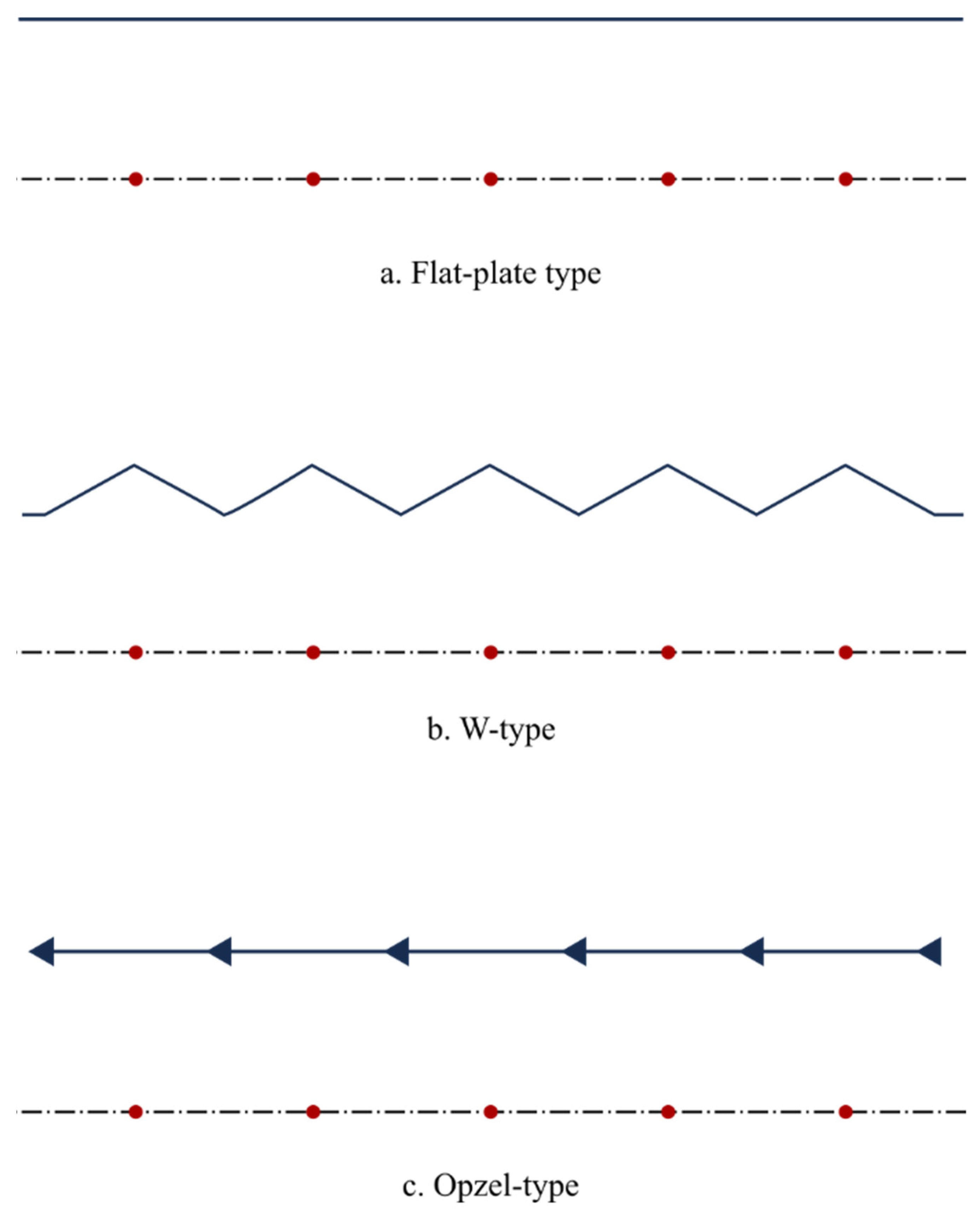
4.1.3. Collecting Electrode Geometry

Changing the collecting electrode geometry can alter the performance of an ESP significantly. This is because bending the collecting plate creates a region with a high-intensity electric field near the collecting plate [4,11,27,54]. Another benefit is that changing the design of the collection electrode improves the capturing process of the precipitated particles [4,27] in the case of C- and W-type collection plates, which is especially prevalent for two-stage ESPs.
Examples of different collecting plate designs are shown in Figure 7. The location of the collecting plates within an industrial ESP is shown in Figure 8 for a wire-plate ESP. The arrangement of opzel-type plates is parallel to the direction of the gas flow. In industrial plants, collection hoppers are often located below the collecting plates, while the transformers of the high-voltage power supplies are located at the top, alongside the control systems.
Evaluating this property is quite important for the optimization of the overall ESP geometry, as different plate geometries differ in their respective characteristics, such as electrical properties (I–V characteristics, current density uniformity, and electric field distribution) and gas flow disturbances. However, the formed ionic wind is usually very similar when neglecting the effects of the main flow [54].
In addition to the aforementioned geometries, the overall precipitation performance can also be influenced by other geometric parameters, such as the width of the collecting plates (channel length) [9]. Other variables, such as the existence of uneven collection plates, can affect the flow suppression in regions close to these plates [59].

4.1.4. Collecting Electrode Spacing

Unlike the effect that the discharge wire spacing has on collection efficiency, the effect of plate-to plate spacing is much more prominent [18,19], making it one of the more important criteria when evaluating the performance of an ESP. Generally, the collection efficiency is higher for narrower channel widths (less spacing) between subsequent plates (assuming constant current density) [5,11,16,18]. The effect is especially apparent in wire-plate type and transverse plate ESPs (Figure 1 and Figure 2, respectively).

4.1.5. Pre-Charger Length to Collection Stage Length Ratio (Multi-Stage ESP)

Some studies evaluated the effects that changing the length of pre-chargers (in case of multi-stage ESPs, Figure 4) has on the collection efficiency. Increasing the pre-charge stage length while shrinking the length of the collection stage increased the overall collection efficiency of sub-micron particles [5]. In the case of particles ≥0.1 μm, this had the opposite effect, as extending the collection stage allowed these particles an increased approaching time, allowing the collection efficiency to increase [5].

4.1.6. Discharge Electrode Eccentricity (Wire-Cylinder Type)

Some parameters are unique to the cylindrical-type ESP, such as the effect of emitting wire eccentricity from the center of the cylinder [56,60]. While smaller eccentricities do not really affect the overall behavior of the cylindrical ESP, more extreme shifts of the wire can cause vortices, as they severely disturb the radial movement of the dust particles [61].
Refer to Table 1 for a summary of works regarding ESP geometry optimization. Major design parameters such as ESP type, and emitting and collecting electrode geometries and dimensions are specified, as well as the flow speed and the properties and concentration of the collected particles. Barbed wires and different collecting electrode geometries are some of the well-researched areas.

4.2. Electrohydrodynamic Flow

Electrohydrodynamic (EHD) flow is a fluidic flow given rise to by the coupling of the primary flow and the “ionic wind”, which is the result of the collision between ions and neutral particles, resulting in a momentum transfer to neutral particles. The ionic wind takes place within the electrode gap of an ESP and, thus, has a prominent effect on particle transport within an ESP. Many works used the EHD flow characteristics as a performance parameter for ESPs [15,27,28,29,30,31]. Experimental models that use Particle Image Velocimetry (PIV) [62,63,64,65] and numerical models were developed to study these effects [28,66], where a classification system based on the number of vortexes and their structure was proposed [66].

4.2.1. EHD Flow Effects on Flow Profile Collection Efficiency

Neglecting the effect of EHD flow of the ESP fluid flow will result in a constant flow velocity close to the precipitator boundary [29]. When considering it, however, the flow velocity becomes unstable close to the plate, and high-velocity vortexes are formed [29] because of the ionic wind effect that drives the gas particle from the discharge electrode to the collection plates.
The aforementioned effects contribute to a lower collection efficiency when EHD is considered; this is because the increased flow near the collection electrode can cause particles to escape. These negative effects are especially detrimental for the collection efficiency of smaller particles with lower mass, as their reduced inertia makes them more susceptible to the variation of flow [29].

4.2.2. EHD Flow Effects on Particle Deposition Rate

EHD flow can negatively impact the deposition rate of particles, regardless of the flow velocity [29]. This effect, however, is more prominent when the flow velocity is lower [29,67]. Expanding on the effects on flow velocity, it can be deduced that disregarding EHD effect will lead to a less-turbulent flow.
A special case that can be considered is that of barbed discharge electrodes with a needle tip pointing in the collecting plate direction, as the discharge ions cannot reach the base of the barb, where it is considered an ion-free region [29]. More particles are charged when passing near the discharge electrode if we considered EHD flow, as it makes the particles circulate near the non-ionic region at the base of the barb [29]. This leads to an increase of the overall collection efficiency, an effect that is more prominent at lower velocities [29].

4.3. The Effect of Gas-Flow Velocity

Gas flow velocities can also affect the precipitation efficiency [5,18,68]. It is generally accepted that a reduced gas inlet velocity increases the overall precipitation efficiency [18]. This is the case because any increase in the flow velocity will lead to a reduction of the particle charging time [69]. Gas-flow velocities over the current limit of about 1.5 m/s will lead to substantially reduced precipitation performance [70]. If the effect of gas velocity is of interest, it is preferable to use the model of Zhibin and Guoquan [22], as it is the closest to experimental data in this regard [58].

4.4. The Effect of Power Consumption and Number of Emitting Electrodes

There is a direct relation between ESP collection efficiency and its power input. A greater input power yields a higher efficiency, which is initially apparent when a small increase in power input results in a great improvement in the collection efficiency. However, when a larger amount of input power is used, the improvement in the collection efficiency is not as prominent due to the back-corona initiation [43,71]. Some works investigated the effect of using additional emitting electrodes, and it was found that this method can increase the precipitation efficiency, while consuming less power [15].
Table 1. Summary of papers evaluating ESP performance based on specific geometric parameters.
Author, Reference NumberESP TypeEmitting Electrode, Diameter, Spacing/LengthCollecting Electrode Geometry, SpacingFlow SpeedParticle Type, Size, ConcentrationCollection Efficiency, Equation Number
Lagarias [43]Wire-plate typeSquare profile/spaced disks/ barbed, variable diameter, 203.2 mmFlat plate, 152.4 mmN/AN/A, 10 µm, N/ADeutsch-White model, Equation (3)
Fujishima [72]Wire-plate typeBarbed wires, 0.2 mm, 50 mmFlat plate, 80 mm0.1, 0.5, 1 m/sDust, 11–11.5 µm, variableN/A
Heng [27]Wire-plate typeSmooth cylinder, 5 mm, 24 0 mmFlat plate, rod-curtain, W-, C-, and opzel types, 250 mm0.5–1 m/sN/AN/A
Abdel-Sattar [18]Wire-plate type0.254 mm, 0.2 m, unity surface factorFlat plate, 200 mm10 m/sSpherical, N/A, constant concentrationGeneral method, Equation (2)
Miller [37]Wire-plate typeBarbed, 10 mm, 75–175 mmFlat plate, N/AN/ALimestone dust, 6 µm, 0.1 g/m3Fractional efficiency
Farnoosh [73]Wire-plate typeSmooth cylinder, N/A, single wire/100 mmFlat plate, 100 mm1 m/sSpherical, 0.3–90 µm, 998.2 kg/m3General method, Equation (2)
Farnoosh [46]Wire-plate typeSpiked wire (single- and double- sided spikes), 10 mm, single wire/200 mmFlat plate, 100 mm0.6 m/sN/A, 0.25–1.5 µm, 998.2 kg/m3General method, Equation (2)
Ning [15]Wire-plate typeSmooth cylinder, 0.09 mm, 0.1–0.2 mFlat plate, 200–400 mm0.2 m/sSpherical, 20 nm to 6.35 µm, variable General method, Equation (2)
He [74]Wire-plate typeSmooth cylinder, 1 mm, 40–60–80 mmFlat plate, variableStatic, 1–3.37 m/sVariable, 2.5–10 µm, variable (100–200–300 µg/m3)Experimental (DRX-1, DRX-2)
Hao [55]Wire-plate type0.2–1.6, 2.2–3.5 mm, 300–333 mmFlat plate, 300 mm0.25 m/sN/AN/A
Navarrete [19]Wire-plate typeBarbed, N/AFlat plate, 300–400 mm0.8–1.8 m/sAsh, variable, variableGeneral method, Equation (2)
Kim [58]Wire-plate typeSmooth cylinder, 1 mm, 37.5 mmFlat plate, 300 mm1 m/sVariable, 0.2–200 µm, variableN/A
Kasdi [9]Wire-plate typeSmooth cylinder, 0.4–0.8 mm, 40–60–80 mmFlat plate, 100 mmN/AN/AN/A
Chibane [75]Wire-plate typeSmooth cylinder, 0.25 mm, 40–60–80 mmC-, tri-, w-, corrugated, crenelated and flat types, 200 mm0–1 m/s1–10 µm, 3900 kg/m3General method, Equation (2)
Choi [76]Wire-plate typeSmooth cylinder, 0.1 mm, 100 mmSeveral wavy types, flat type, 50 mm2 m/sN/AGeneral method, Equation (2)
Ruttanachot [77]Wire-plate typeN/A, 64, 85 mmFlat plate, 50–75 mm0.063 m/sN/A, 0.68 µm, variable (average 498.1 mg/m3)Deutsch-Anderson model, Equation (3)
Zhu [59]Wire-plate typeSmooth cylinder, 1 mm, 200 mmC-, tri-, w-, corrugated, crenelated and flat types, 200 mm0–1 m/s1–10 µm, 3900 kg/m3General method, Equation (2)
Pal [70]Wire-plate typeCup-type, 5 mm, 240 mmFlat plate, w-type, 200 mm1 m/sN/AGeneral method, Equation (2)
Yan [14]Wire-plate typeBarbed, 20 mm, 480 mmC-type plate, 400 mm0.4–0.8 m/sN/AGeneral method, Equation (2)
Lee [38]Wire-plate typePipe-and-spike electrode, N/A, 20 mmFlat plate, 50 mm0–1 m/sN/AGeneral method, Equation (2)
Lee [6]Plate-plate type, 2-stageSpiked edge-type electrode, N/AFlat plate, 10 mm1 m/sOil mist, 2.5 µm, N/AGeneral method, Equation (2)
Gao [67]Wire-plate type, 2-stageSmooth cylinder, square (90°/45° config.), needle wire, 3.5 mmFlat plate, BE-type plate, 400 mm1 m/s0.05–10 µm, N/AGeneral method, Equation (2)
Gao [5]Wire-plate type, 2-stageSmooth cylinder, 0.22 mm, single wireFlat plate, 10–50 mm0.5–2 m/s0.4–4 µm, 2200 kg/m3General method, Equation (2)
Zhu [4]Wire-plate type, 2-stageSmooth cylinder, 0.1 mm, single wireW-type plate, 6 mm0–2.5 m/s0.3–1 µm, 1.225 kg/m3General method, Equation (2)
Shen [69]Transverse-plate typeSmooth cylinder, N/ACurved transverse, 100 mm~0.2–1.7 m/s16 nm–10 µm, 1000 kg/m3General method, Equation (2)
Yi [78]Transverse-plate typeSmooth cylinder, N/ADouble C-plate, 40 mm3.5 m/sAsh, ≤60 µmN/A
Xiang [25]Transverse-plate typeSmooth cylinder, 2 mm, 400 mmSimple transverse, 200 mm1–1.5 m/sDust, 25.405 µm, 500–1300 mg/m3General method, Equation (2)
Chang [7]Transverse-plate typeBarbed, 20 mm, 480 mmC-plate, 480 mm0.8 m/sTalcum powder, 11.6 µm, variableCombined, Equation (13)
Zhuang [79]Wire-cylinder type0.3–0.5 mm, N/ACylindrical, 15 mm radius, 150 mm long0.35–0.7 m/sVarious, 0.5–50 µm, variableGeneral method, Equation (2)
Yamamoto [42]Wire-cylinder type6.35 mm, 416 mm longCylindrical, 25 mm radius, 416 mm long1.9–2.1 m/sDiesel emissions, 0.2–2.5 µm, N/AGeneral method, Equation (2)
Niewulis [61]Wire-cylinder type0.23 mm, 100 mm longCylindrical, 12.75 mm radius, 200 mm long0.9 m/sN/AN/A
Bacher [56]Wire-cylinder typeCylindrical/barbed, 0.2 mm, N/ACylindrical, 125 mm radius, 5000 mm long1.36 m/s0.082 µm (mean), N/AMass-related separation method
Hwang [39]Wire-cylinder type“Sawtooth”, 35–75 mm, 20–100 mmCylindrical, 100 mm radius, 555 mm long1 m/sVariableGeneral method, Equation (2)

5. Discussion and Conclusions

This review presented the main elements of single-stage electrostatic precipitators, along with different methods used to assess the performance of the ESP. Starting with the collection efficiency, this can be evaluated using several approaches. The majority of the models are based on the Deutsch model. While this model is easy to adapt, it is flawed due to the assumption of uniform diffusion within the flow. Modifications such as the Zhibin and Guoquan model tried to solve this by considering the effect of diffusion. More complex models considered the type of precipitated materials or inertial forces in the case of transverse-plate ESPs.
The geometry of discharge electrodes greatly affects the precipitator’s performance. The design variation of discharge wires, such as sawtooth discharge plates and barbed wires, as opposed to smooth cylindrical wires, enjoy a wide adaption in the industry. Using barbed discharge can greatly increase the precipitation performance, with shorter barbs/spikes being more effective in achieving better efficiency. Increasing the number of spikes increases the collection efficiency, except when the spikes are too close, which can result in a homogenous electric field. Smaller discharge wire radii allow for the corona discharge to occur faster. Using more emitting electrodes increases the collection efficiency while consuming less power. As for collecting plates, bending to them leads to an increase in the electric field intensity, which in turn can improve the collection efficiency. Changing the design of the collection electrode can also help with capturing and limiting the re-entrainment of particles. Precipitation performance can increase with decreased spacing between subsequent collection plates.
An increasingly important metric is the corona power ratio. It can measure the power consumption with respect to the gas flow rate, which is one of the economic considerations for industrial precipitators. Additionally, industrial precipitators can benefit from using non-traditional materials that are more resistant to corrosive environments that are common in the industry. Evaluating current-voltage characteristics is another method of assessing the performance of the ESP by monitoring the change in I–V characteristics when changing one or more element. These changes are often verified experimentally against industrial precipitators or lab setups. The impact of changing each of the main design elements of the discharge and collecting electrodes has been assessed through previous works.
Collisions of charged and neutral particles produce an EHD flow within the ESP electrode gap, meaning that EHD flow can greatly influence particle transport. This behavior was studied through several numerical models. The resulting turbulent flow profile is unstable, with vortexes within it contributing to lower collection efficiencies. Regarding the deposition rate of particles, EHD flow contributes to higher deposition rates at a lower flow velocity, increasing the overall collection efficiency.
As for gas flow velocity, lower gas inlet velocities generally yield higher precipitation efficiencies, as increasing the flow velocity will lead to a reduction of the particle charging time. Power consumption is another factor that affects the precipitation efficiency. A greater input power yields a higher efficiency, at least until a certain threshold, because after this limit, larger input power values do not continue to increase the efficiency linearly. Using additional emitting electrodes with a lower input power can aid with increasing the precipitation efficiency.

6. Future Work

Further optimization for the geometry of both discharge electrodes and collecting plates is needed to maximize the precipitation performance of electrostatic precipitators. This can mainly be achieved through utilizing a numerical simulation, where new models are still being actively developed [38,67,76]. Some progress has already been made in this regard [38,39], but it is still yet to be applied for specific operating conditions.
More advanced numerical models will also be beneficial in further optimizing geometries of ESPs to surpass the current gas flow velocity limit of about 1.5 m/s [70]. Additionally, these models can aid with overcoming high-voltage requirements of ESPs, lowering the operation cost and partially negating the need for special anti-corrosion electrode materials. As most models use simplifications such as neglecting electrohydrodynamic flow, the diffusion effect on gas flow due to concentration variation, or particle distribution patterns, developing more complete models will help with designing ESP geometries with higher collection efficiencies for sub-micron particulate matter [59,76]. The optimized geometries should focus on limiting charged particle re-entrainment and consider the interaction between the secondary EHD flow and the main flow [59].
Another area that requires further research is the selection of optimum discharge and collecting electrode materials in terms of corrosion compliance for long-term operation. This is especially relevant in industrial applications, where ESPs are susceptible to corrosive materials. The use of multiple stages can partially aid with achieving this goal [6,34].

Author Contributions

Conceptualization, M.B. and A.M.M.; methodology, M.B. and A.M.M.; investigation, M.B. and A.M.M.; writing—original draft preparation, A.M.M.; writing—review and editing, M.B.; visualization, M.B. and A.M.M.; supervision, M.B. All authors have read and agreed to the published version of the manuscript.

Funding

The APC is supported by The American University in Cairo (AUC) Grant no: SSE-MENG-M.B.-MG-Type B-FY23.

Data Availability Statement

Not applicable.

Conflicts of Interest

The authors declare no conflict of interest.

References

  1. White, H.J. Fifty Years of Electrostatic Precipitation. J. Air Pollut. Control. Assoc. 1957, 7, 166–177. [Google Scholar] [CrossRef]
  2. Parker, K.R. Applied Electrostatic Precipitation; Blackie: London, UK, 1997; ISBN 978-0-7514-0266-7. [Google Scholar]
  3. Mizuno, A. Electrostatic Precipitation. IEEE Trans. Dielect. Electr. Insul. 2000, 7, 615–624. [Google Scholar] [CrossRef]
  4. Zhu, Y.; Chen, C.; Shi, J.; Shangguan, W. Enhancement of Air Purification by Unique W-Plate Structure in Two-Stage Electrostatic Precipitator: A Novel Design for Efficient Capture of Fine Particles. Adv. Powder Technol. 2020, 31, 1643–1658. [Google Scholar] [CrossRef]
  5. Gao, M.; Zhu, Y.; Yao, X.; Shi, J.; Shangguan, W. Dust Removal Performance of Two-Stage Electrostatic Precipitators and Its Influencing Factors. Powder Technol. 2019, 348, 13–23. [Google Scholar] [CrossRef]
  6. Lee, Y.; Sung, J.-H.; Han, B.; Kim, Y.-J.; Kim, H.-J. Particle Removal Performance of a Two Stage Electrostatic Precipitator with Carbon Based Nonmetallic Collection Plates for Oil Mist. In Proceedings of the 2020 IEEE Industry Applications Society Annual Meeting, Detroit, MI, USA, 10–16 October 2020; pp. 1–7. [Google Scholar]
  7. Chang, Y.; Jia, P.; Shi, L.; Xiang, X. Corona Discharging and Particle Collection of Bipolar Transverse Plate ESP. J. Electrost. 2018, 96, 104–110. [Google Scholar] [CrossRef]
  8. Nikas, K.S.P.; Varonos, A.A.; Bergeles, G.C. Numerical Simulation of the Flow and the Collection Mechanisms inside a Laboratory Scale Electrostatic Precipitator. J. Electrost. 2005, 63, 423–443. [Google Scholar] [CrossRef]
  9. Kasdi, A. Computation and Measurement of Corona Current Density and V–I Characteristics in Wires-to-Plates Electrostatic Precipitator. J. Electrost. 2016, 81, 1–8. [Google Scholar] [CrossRef]
  10. Conesa, A.J.; Sanchez, M. The Current–Voltage Characteristics of Corona Discharge in Wire to Cylinder in Parallel Electrode Arrangement. IEEE Trans. Plasma Sci. 2018, 46, 3022–3030. [Google Scholar] [CrossRef]
  11. Mansour, A.; Badran, M. Modelling and Simulating the Effect of the Different Geometric Parameters on Voltage-Current Characteristics for Wire-Plate Electrostatic Precipitator with Different Collector Configurations. In Proceedings of the 2020 21st International Conference on Thermal, Mechanical and Multi-Physics Simulation and Experiments in Microelectronics and Microsystems (EuroSimE), Cracow, Poland, 5–8 July 2020; pp. 1–8. [Google Scholar]
  12. Ait Said, H.; Aissou, M.; Nouri, H.; Zebboudj, Y. Analysis of the Current-Voltage Characteristic during the Corona Discharge in Wires-To-Planes Electrostatic Precipitator under Variable Air Humidity. Acta Phys. Pol. A 2019, 135, 320–325. [Google Scholar] [CrossRef]
  13. Khaled, U.; Beroual, A.; Alotaibi, F.; Khan, Y.; Al-Arainy, A. Experimental and Analytical Study on the Performance of Novel Design of Efficient Two-Stage Electrostatic Precipitator. IET Sci. Meas. Technol. 2018, 12, 486–491. [Google Scholar] [CrossRef]
  14. Yan, D.; Zhang, Z.; Gong, H.; Ya, Y. Effect of Barbed Tubular Electrode Corona Discharge EHD Flow on Submicron Particle Collection in a Wide-Type ESP. J. Electrost. 2021, 109, 103545. [Google Scholar] [CrossRef]
  15. Ning, Z.; Podlinski, J.; Shen, X.; Li, S.; Wang, S.; Han, P.; Yan, K. Electrode Geometry Optimization in Wire-Plate Electrostatic Precipitator and Its Impact on Collection Efficiency. J. Electrost. 2016, 80, 76–84. [Google Scholar] [CrossRef]
  16. Chang, C.-L.; Bai, H. Effects of Some Geometric Parameters on the Electrostatic Precipitator Efficiency at Different Operation Indexes. Aerosol Sci. Technol. 2000, 33, 228–238. [Google Scholar] [CrossRef]
  17. Jaworek, A.; Krupa, A.; Czech, T. Modern Electrostatic Devices and Methods for Exhaust Gas Cleaning: A Brief Review. J. Electrost. 2007, 65, 133–155. [Google Scholar] [CrossRef]
  18. Abdel-Sattar, S. Influence of Geometrical Parameters upon Electrostatic Precipitator Efficiency. Compel 1991, 10, 27–43. [Google Scholar] [CrossRef]
  19. Navarrete, B.; Cañadas, L.; Cortés, V.; Salvador, L.; Galindo, J. Influence of Plate Spacing and Ash Resistivity on the Efficiency of Electrostatic Precipitators. J. Electrost. 1997, 39, 65–81. [Google Scholar] [CrossRef]
  20. Gouri, R.; Zouzou, N.; Tilmatine, A.; Moreau, E.; Dascalescu, L. Collection Efficiency of Submicrometre Particles Using Single and Double DBD in a Wire-to-Square Tube ESP. J. Phys. D Appl. Phys. 2011, 44, 495201. [Google Scholar] [CrossRef]
  21. Neimarlija, N.; Demirdžić, I.; Muzaferija, S. Numerical Method for Calculation of Two-Phase Electrohydrodynamic Flows in Electrostatic Precipitators. Numerical. Heat Transfer. Part A Appl. 2011, 59, 321–348. [Google Scholar] [CrossRef]
  22. Zhibin, Z.; Guoquan, Z. New Model of Electrostatic Precipitation Efficiency Accounting for Turbulent Mixing. J. Aerosol Sci. 1992, 23, 115–121. [Google Scholar] [CrossRef]
  23. Cooperman, P. A New Theory of Precipitator Efficiency. Atmos. Environ. 1971, 5, 541–551. [Google Scholar] [CrossRef]
  24. EL-Rifai, M. Dispersion and Transport in Turbulent Pipe Flow; The University of Oklahoma: Norman, OK, USA, 1965; ISBN 9798659904091. [Google Scholar]
  25. Xiang, X.; Chang, Y.; Nie, Y. Investigation of the Performance of Bipolar Transverse Plate ESP in the Sintering Flue Control. J. Electrost. 2015, 76, 18–23. [Google Scholar] [CrossRef]
  26. Dong, M.; Zhou, F.; Zhang, Y.; Shang, Y.; Li, S. Numerical Study on Fine-Particle Charging and Transport Behaviour in Electrostatic Precipitators. Powder Technol. 2018, 330, 210–218. [Google Scholar] [CrossRef]
  27. Shen, H.; Yu, W.; Jia, H.; Kang, Y. Electrohydrodynamic Flows in Electrostatic Precipitator of Five Shaped Collecting Electrodes. J. Electrost. 2018, 95, 61–70. [Google Scholar] [CrossRef]
  28. Zhao, L.; Adamiak, K. Numerical Simulation of the Effect of EHD Flow on Corona Discharge in Compressed Air. IEEE Trans. Ind. Applicat. 2013, 49, 298–304. [Google Scholar] [CrossRef]
  29. Guo, J.; Ye, X.; Wang, S.; Guo, B.; Zhang, C.; Su, Y. The Influence of Electrohydrodynamic Secondary Flow on the Collection Efficiency and Deposition Pattern in ESP. Math. Probl. Eng. 2019, 2019, 8923030. [Google Scholar] [CrossRef]
  30. Feng, Z.; Long, Z.; Adamiak, K. Numerical Simulation of Electrohydrodynamic Flow and Vortex Analysis in Electrostatic Precipitators. IEEE Trans. Dielect. Electr. Insul. 2018, 25, 404–412. [Google Scholar] [CrossRef]
  31. Monrolin, N.; Praud, O.; Plouraboué, F. Electrohydrodynamic Ionic Wind, Force Field, and Ionic Mobility in a Positive Dc Wire-to-Cylinders Corona Discharge in Air. Phys. Rev. Fluids 2018, 3, 063701. [Google Scholar] [CrossRef]
  32. Zheng, C.; Liang, C.; Liu, S.; Yang, Z.; Shen, Z.; Guo, Y.; Zhang, Y.; Gao, X. Balance and Stability between Particle Collection and Re-Entrainment Inawide Temperature-Range Electrostatic Precipitator. Powder Technol. 2018, 340, 543–552. [Google Scholar] [CrossRef]
  33. Soldati, A. Cost-Efficiency Analysis of a Model Wire-Plate Electrostatic Precipitator via DNS Based Eulerian Particle Transport Approach. Aerosol Sci. Technol. 2003, 37, 171–182. [Google Scholar] [CrossRef]
  34. Sung, J.-H.; Kim, S.; Kim, M.; Lee, Y.; Kim, Y.-J.; Han, B.; Kim, H.-J. Maintaining the PM Removal Efficiency of a Two-Stage ESP With External Ion-Injection Discharge via a Water Film on the Collection Plate and Cleaning of the Ionizer. IEEE Trans. Ind. Applicat. 2022, 58, 792–799. [Google Scholar] [CrossRef]
  35. Kim, H.-J.; Han, B.; Woo, C.G.; Kim, Y.-J. Ozone Emission and Electrical Characteristics of Ionizers with Different Electrode Materials, Numbers, and Diameters. IEEE Trans. Ind. Applicat. 2017, 53, 459–465. [Google Scholar] [CrossRef]
  36. Mo, J.; Tian, E.; Pan, J. New Electrostatic Precipitator with Dielectric Coatings to Efficiently and Safely Remove Sub-Micro Particles in the Building Environment. Sustain. Cities Soc. 2020, 55, 102063. [Google Scholar] [CrossRef]
  37. Miller, J.; Hoferer, B.; Schwab, A.J. The Impact of Corona Electrode Configuration on Electrostatic Precipitator Performance. J. Electrost. 1998, 44, 67–75. [Google Scholar] [CrossRef]
  38. Lee, G.-H.; Hwang, S.-Y.; Cheon, T.-W.; Kim, H.-J.; Han, B.; Yook, S.-J. Optimization of Pipe-and-Spike Discharge Electrode Shape for Improving Electrostatic Precipitator Collection Efficiency. Powder Technol. 2021, 379, 241–250. [Google Scholar] [CrossRef]
  39. Hwang, S.-J.; Hwang, S.-Y.; Kim, H.-J.; Yook, S.-J. Optimization of Sawtooth Electrode for Improving Collection Efficiency of Electrostatic Precipitator. In Proceedings of the 2021 IEEE Industry Applications Society Annual Meeting (IAS), Vancouver, BC, Canada, 10–14 October 2021; pp. 1–8. [Google Scholar]
  40. Kim, Y.-J.; Han, B.; Woo, C.G.; Kim, H.-J. Ultrafine Particle Collection Performance of a Two-Stage ESP With a Novel Mixing-Type Charging Stage Using Different Geometries and Electrical Conditions. IEEE Trans. Ind. Applicat. 2017, 53, 5859–5866. [Google Scholar] [CrossRef]
  41. Jaworek, A.; Sobczyk, A.T.; Marchewicz, A.; Krupa, A.; Czech, T.; Śliwiński, Ł.; Ottawa, A.; Charchalis, A. Two-Stage vs. Two-Field Electrostatic Precipitator. J. Electrost. 2017, 90, 106–112. [Google Scholar] [CrossRef]
  42. Yamamoto, T.; Maeda, W.; Ehara, Y.; Kawakami, H. Development of EHD-Enhanced Plasma Electrostatic Precipitator. In Proceedings of the 2011 IEEE Industry Applications Society Annual Meeting, Orlando, FL, USA, 9–13 October 2011; pp. 1–7. [Google Scholar]
  43. Lagarias, J.S. Discharge Electrodes and Electrostatic Precipitators. J. Air Pollut. Control. Assoc. 1960, 10, 271–274. [Google Scholar] [CrossRef]
  44. Adamiak, K.; Atten, P. Numerical Simulation of the 2-D Gas Flow Modified by the Action of Charged Fine Particles in a Single-Wire ESP. IEEE Trans. Dielect. Electr. Insul. 2009, 16, 608–614. [Google Scholar] [CrossRef]
  45. Karwat, B.; Nocun, M.; Machnik, R.; Niedzwiedzki, J. Modelling and Study the Effect of Selected Design Features for the Operating Parameters. Eksploat. Niezawodn. 2016, 18, 325–332. [Google Scholar] [CrossRef]
  46. Farnoosh, N.; Adamiak, K.; Castle, G.S. Numerical Calculations of Submicron Particle Removal in a Spike-Plate Electrostatic Precipitator. IEEE Trans. Dielect. Electr. Insul. 2011, 18, 1439–1452. [Google Scholar] [CrossRef]
  47. Farnoosh, N.; Adamiak, K.; Castle, G.S.P. Three-Dimensional Analysis of Electrohydrodynamic Flow in a Spiked Electrode-Plate Electrostatic Precipitator. J. Electrost. 2011, 69, 419–428. [Google Scholar] [CrossRef]
  48. Fujishima, H.; Morita, Y.; Okubo, M.; Yamamoto, T. Numerical Simulation of Three-Dimensional Electrohydrodynamics of Spiked-Electrode Electrostatic Precipitators. IEEE Trans. Dielectr. Electr. Insul. 2006, 13, 160–167. [Google Scholar] [CrossRef]
  49. Guo, B.Y.; Guo, J.; Yu, A.B. Simulation of the Electric Field in Wire-Plate Type Electrostatic Precipitators. J. Electrost. 2014, 72, 301–310. [Google Scholar] [CrossRef]
  50. Guo, B.-Y.; Yu, A.-B.; Guo, J. Numerical Modeling of Electrostatic Precipitation: Effect of Gas Temperature. J. Aerosol Sci. 2014, 77, 102–115. [Google Scholar] [CrossRef]
  51. Guo, B.; Yu, A.; Guo, J. Numerical Modelling of ESP for Design Optimization. Procedia Eng. 2015, 102, 1366–1372. [Google Scholar] [CrossRef]
  52. Atten, P.; Dumitran, L.; Blanchard, D. Numerical Simulation of Fine Particles Charging and Collection in an Electrostatic Precipitator with Regular Barbed Electrodes. In Electrostatics 2003; Morgan, H., Ed.; Taylor & Francis: Oxford, UK, 2004; Volume 178, pp. 199–205. ISBN 978-0-7503-0949-3. [Google Scholar]
  53. Yamamoto, T.; Sparks, L.E. Numerical Simulation of Three-Dimensional Tuft Corona and Electrohydrodynamics. IEEE Trans. Ind. Applicat. 1986, IA-22, 880–885. [Google Scholar] [CrossRef]
  54. Chen, B.; Guo, Y.; Li, H.; Liu, B.; He, Y.; Zhao, H. Insights into the Effect of the Shape of Collecting Plates on Particle Precipitation Processes in Electrostatic Precipitator. J. Air Waste Manag. Assoc. 2020, 70, 892–903. [Google Scholar] [CrossRef]
  55. Hao, J.; He, K.; Chao, H. Calculation of Electric Field Strength Distributions for New Electrostatic Precipitator Discharge Electrode Designs. J. Air Waste Manag. Assoc. 1990, 40, 1510–1513. [Google Scholar] [CrossRef]
  56. Bacher, C.; Lebedynskyy, V.; Fischer, S.; Riebel, U. Discharge Electrode Geometry and Energy Efficiency in a One-Stage Wire–Tube Electrostatic Precipitator Operating at High Concentrations of Submicron Liquid Aerosol. Environ. Technol. 2020, 41, 2096–2108. [Google Scholar] [CrossRef]
  57. Conesa, A.J.; Sánchez, M.; León, M.; Cabrera, Á. Some Geometrical and Electrical Aspects on the Wire-to-Cylinder Corona Discharge. J. Electrost. 2019, 100, 103355. [Google Scholar] [CrossRef]
  58. Kim, S.H.; Lee, K.W. Experimental Study of Electrostatic Precipitator Performance and Comparison with Existing Theoretical Prediction Models. J. Electrost. 1999, 48, 3–25. [Google Scholar] [CrossRef]
  59. Zhou, W.; Jiang, R.; Sun, Y.; Chen, B.; Liu, B. Study on Multi-Physical Field Characteristics of Electrostatic Precipitator with Different Collecting Electrodes. Powder Technol. 2021, 381, 412–420. [Google Scholar] [CrossRef]
  60. Tirumala, R.; Go, D.B. Comparative Study of Corona Discharge Simulation Techniques for Electrode Configurations Inducing Non-Uniform Electric Fields. J. Electrost. 2014, 72, 99–106. [Google Scholar] [CrossRef]
  61. Niewulis, A.; Podli, J. Influence of Electrode Geometric Arrangement on the Operation of Narrow Circular Electrostatic Precipitator. Int. J. Plasma Environ. Sci. Technol. 2014, 8, 60–71. [Google Scholar]
  62. Hamdi, M.; Havet, M.; Rouaud, O.; Tarlet, D. Comparison of Different Tracers for PIV Measurements in EHD Airflow. Exp. Fluids 2014, 55, 1702. [Google Scholar] [CrossRef]
  63. Podlinski, J.; Berendt, A.; Mizeraczyk, J. Electrohydrodynamic Secondary Flow and Particle Collection Efficiency in Spike-Plate Multi-Electrode Electrostatic Precipitator. IEEE Trans. Dielect. Electr. Insul. 2013, 20, 1481–1488. [Google Scholar] [CrossRef]
  64. Podlinski, J.; Niewulis, A.; Shapoval, V.; Mizeraczyk, J. Electrohydrodynamic Secondary Flow and Particle Collection Efficiency in a One-Sided Spike-Plate Type Electrostatic Precipitator. IEEE Trans. Dielect. Electr. Insul. 2011, 18, 1401–1407. [Google Scholar] [CrossRef]
  65. Mizeraczyk, J.; Kocik, M.; Dekowski, J.; Dors, M.; Podliński, J.; Ohkubo, T.; Kanazawa, S.; Kawasaki, T. Measurements of the Velocity Field of the Flue Gas Flow in an Electrostatic Precipitator Model Using PIV Method. J. Electrost. 2001, 51–52, 272–277. [Google Scholar] [CrossRef]
  66. Feng, Z.; Long, Z.; Cao, S.; Adamiak, K. Characterization of Electrohydrodynamic (EHD) Flow in Electrostatic Precitators (ESP) by Numerical Simulation and Quantitative Vortex Analysis. J. Electrost. 2018, 91, 70–80. [Google Scholar] [CrossRef]
  67. Gao, W.; Wang, Y.; Zhang, H.; Guo, B.; Zheng, C.; Guo, J.; Gao, X.; Yu, A. Numerical Simulation of Particle Migration in Electrostatic Precipitator with Different Electrode Configurations. Powder Technol. 2020, 361, 238–247. [Google Scholar] [CrossRef]
  68. Ait Said, H.; Nouri, H.; Zebboudj, Y. Effect of Air Flow on Corona Discharge in Wire-to-Plate Electrostatic Precipitator. J. Electrost. 2015, 73, 19–25. [Google Scholar] [CrossRef]
  69. Shen, Y.; Tong, Y.; Zhao, Y.; Zhang, L.; Bu, S.; Xu, W.; Pan, C.; Ding, H.; Yang, Z. Experimental and Computational Study on the Separation Performance of an Electrostatic Precipitator with Curved Transvers Collecting Plates. Adv. Powder Technol. 2021, 32, 1858–1868. [Google Scholar] [CrossRef]
  70. Pal, A.; Dixit, A.; Srivastava, A.K. Design and Optimization of the Shape of Electrostatic Precipitator System. Mater. Today Proc. 2021, 47, 3871–3876. [Google Scholar] [CrossRef]
  71. Darby, K. Pulse Energisation. An Alternative to Conditioning for Highly Resistive Dusts. In Proceedings of the 2nd International Conference on Electrostatic Precipitation, Air Pollution Control Association, Tokyo, Japan, November 1984; pp. 575–584. [Google Scholar]
  72. Fujishima, H.; Ueda, Y.; Tomimatsu, K.; Yamamoto, T. Electrohydrodynamics of Spiked Electrode Electrostatic Precipitators. J. Electrost. 2004, 62, 291–308. [Google Scholar] [CrossRef]
  73. Farnoosh, N.; Adamiak, K.; Castle, G.S. 3-D Numerical Simulation of Particle Concentration Effect on a Single-Wire ESP Performance for Collecting Poly-Dispersed Particles. IEEE Trans. Dielect. Electr. Insul. 2011, 18, 211–220. [Google Scholar] [CrossRef]
  74. He, Z.; Dass, E.T.M.; Karthik, G. Design of Electrostatic Precipitator to Remove Suspended Micro Particulate Matter from Gas Turbine Inlet Airflow: Part I. Experimental Study. J. Aerosol Sci. 2017, 108, 14–28. [Google Scholar] [CrossRef]
  75. Chibane, O.; Rahmani, A.; Smili, K.; Bendahmane, B.; Dascalescu, L.; Kasdi, A. Experimental Characterization of Multi-Wire Corona Electrode Configurations. J. Electrost. 2021, 111, 103575. [Google Scholar] [CrossRef]
  76. Choi, H.Y.; Park, Y.G.; Ha, M.Y. Numerical Simulation of the Wavy Collecting Plate Effects on the Performance of an Electrostatic Precipitator. Powder Technol. 2021, 382, 232–243. [Google Scholar] [CrossRef]
  77. Ruttanachot, C.; Tirawanichakul, Y.; Tekasakul, P. Application of Electrostatic Precipitator in Collection of Smoke Aerosol Particles from Wood Combustion. Aerosol. Air Qual. Res. 2011, 11, 90–98. [Google Scholar] [CrossRef]
  78. Chengwu, Y.; Peng, D.; Chundu, W.; Hongxiang, O.; Wenming, Q.; Shuai, M. Experimental Study of Transportion Characteristic of Charged Particle in a Laboratory Scale High Velocity Electrostatic Precipitator. In Proceedings of the 2010 International Conference on Mechanic Automation and Control Engineering, Wuhan, China, 26–28 June 2010; pp. 2038–2042. [Google Scholar]
  79. Zhuang, Y.; Kim, Y.J.; Lee, T.G.; Biswas, P. Experimental and Theoretical Studies of Ultra-Fine Particle Behavior in Electrostatic Precipitators. J. Electrost. 2000, 48, 245–260. [Google Scholar] [CrossRef]
Figure 1. Single-channel wire-plate ESP.
Energies 15 06647 g001
Figure 2. Schematic of two distinct collecting electrode configurations: (a) transverse plate type ESP; (b) wire-cylinder type ESP.
Energies 15 06647 g002
Figure 3. A typical two-stage ESP separates the charging and collection stages, which allows for increased collection efficiency and more compact packaging.
Energies 15 06647 g003
Figure 4. The main stages of particle collection of an ESP, starting with the corona discharge and gas ionization, to particle transport.
Energies 15 06647 g004
Figure 5. Corona current-voltage characteristics of various ESPs with 3 and 5 discharge electrodes per channel.
Energies 15 06647 g005
Figure 6. The cross-section view of three distinct profiles of barbed discharge electrodes with sharp tips to aid with inducing higher current values.
Energies 15 06647 g006
Figure 7. Various collecting plate designs for a wire-plate type ESP.
Energies 15 06647 g007
Figure 8. Opzel-type collecting plate layout of a single-stage ESP in a cross-sectional view.
Energies 15 06647 g008
Publisher’s Note: MDPI stays neutral with regard to jurisdictional claims in published maps and institutional affiliations.

