
Forces and Stresses in the Windings of a Superconducting Fault Current Limiter


Abstract
:1. Introduction
2. The Design of the Limiter
2.1. Concept
2.2. Cryogenic System
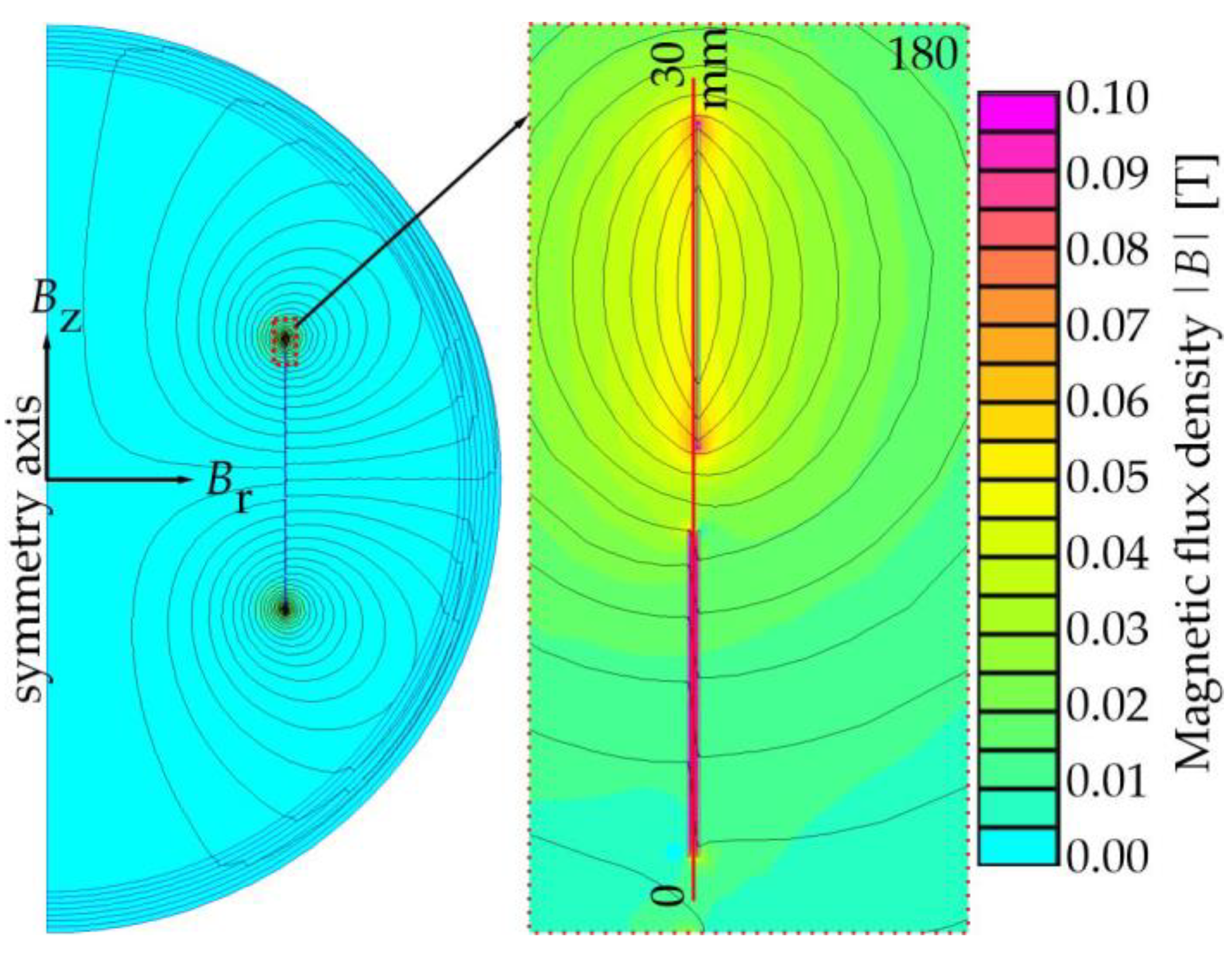
2.3. Numerical Calculation
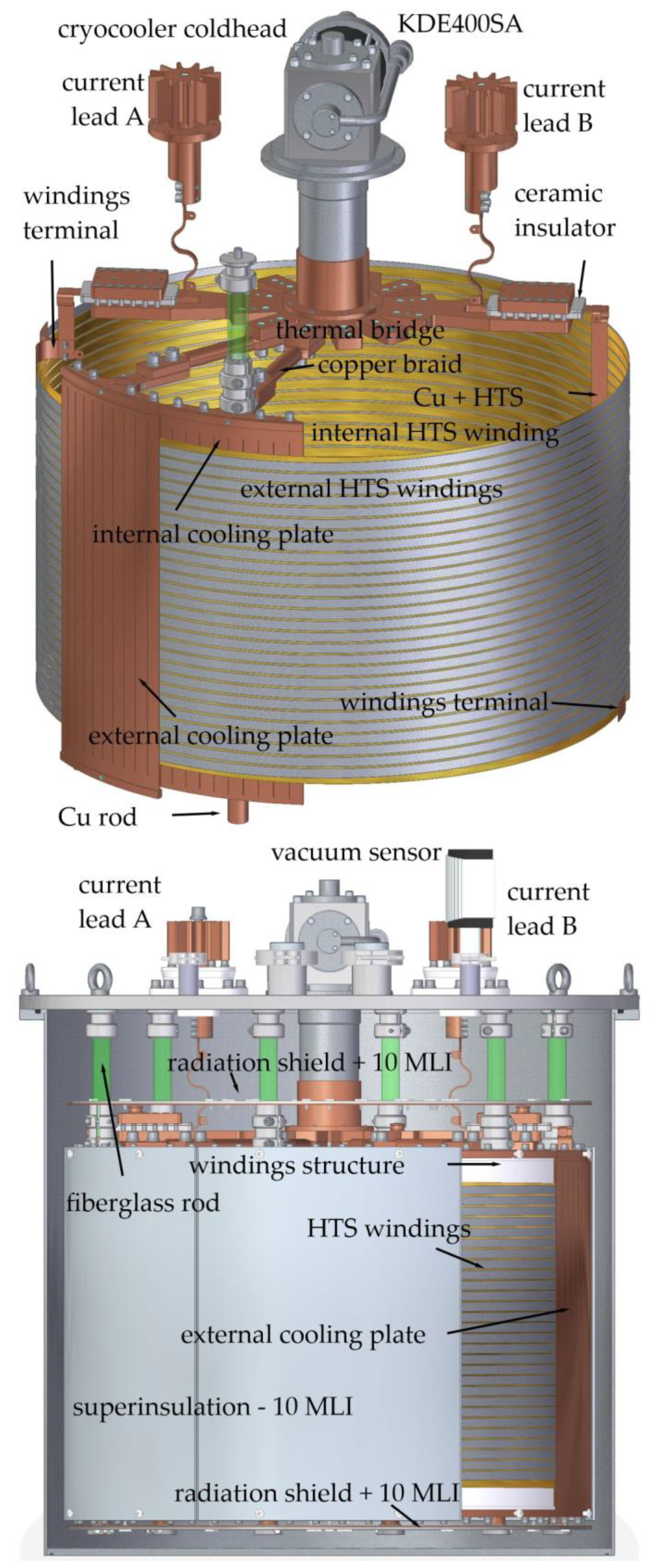
2.4. Design
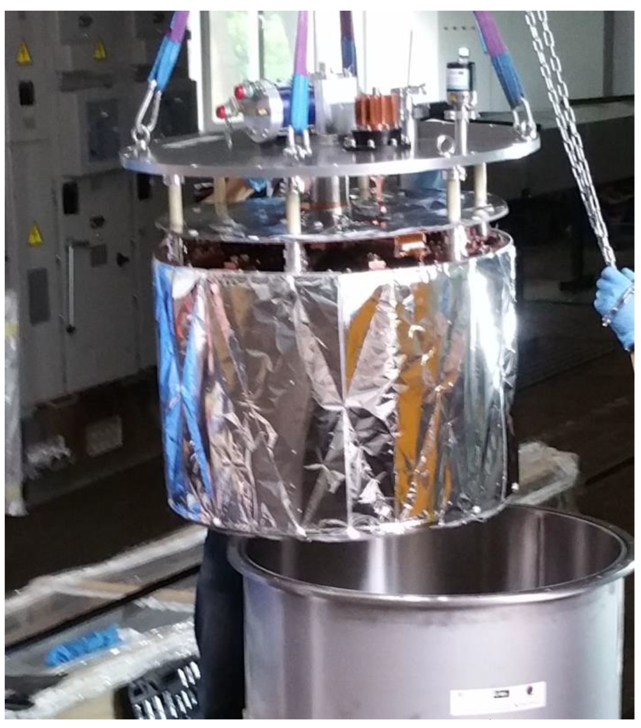
2.5. Manufacturing
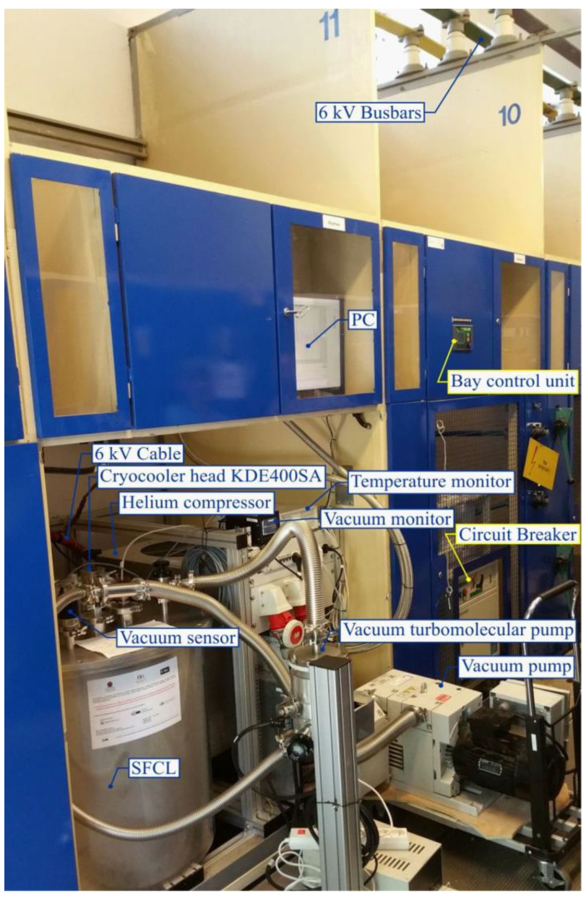
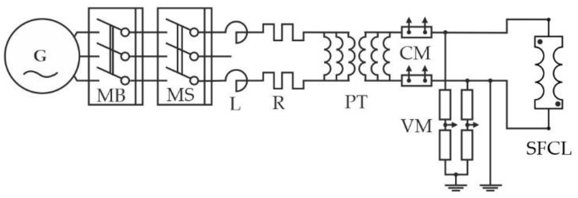
3. Test Setup
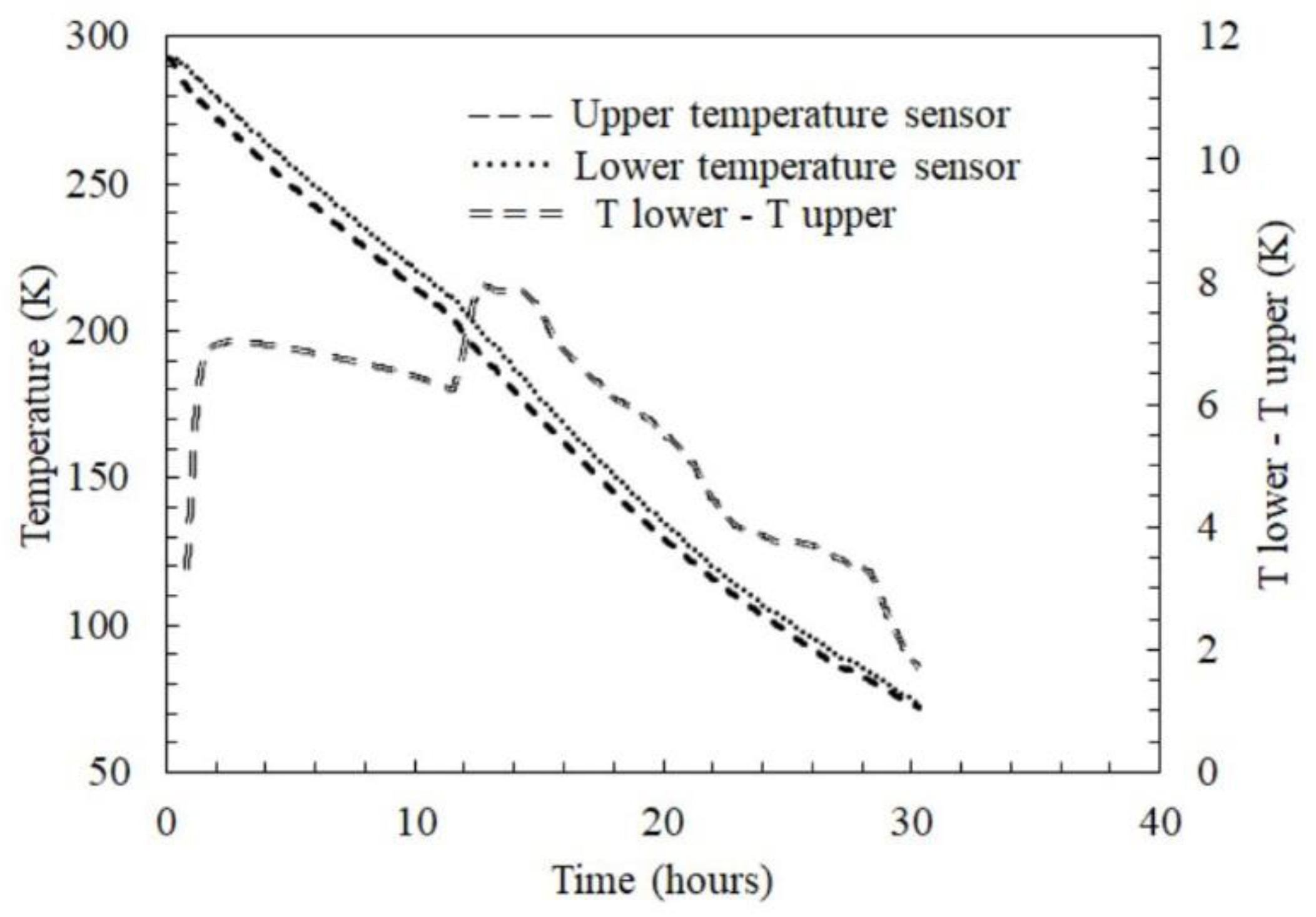
3.1. Cooling the Limiter
3.2. Temperature Measurements
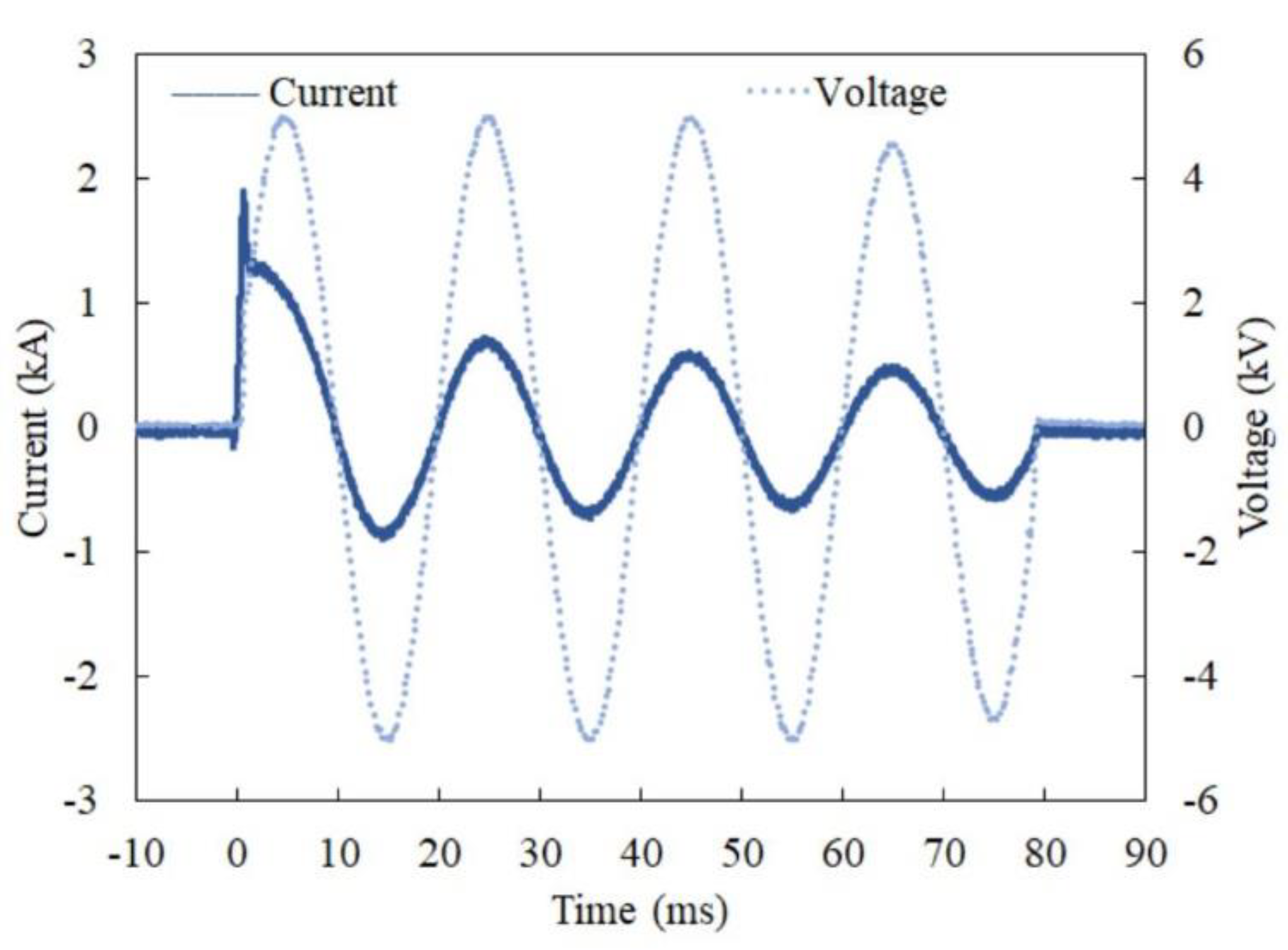
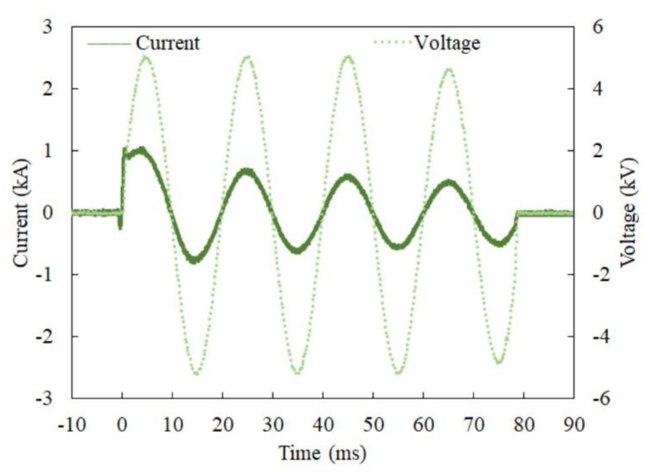
3.3. Measurements of SFCL Parameters
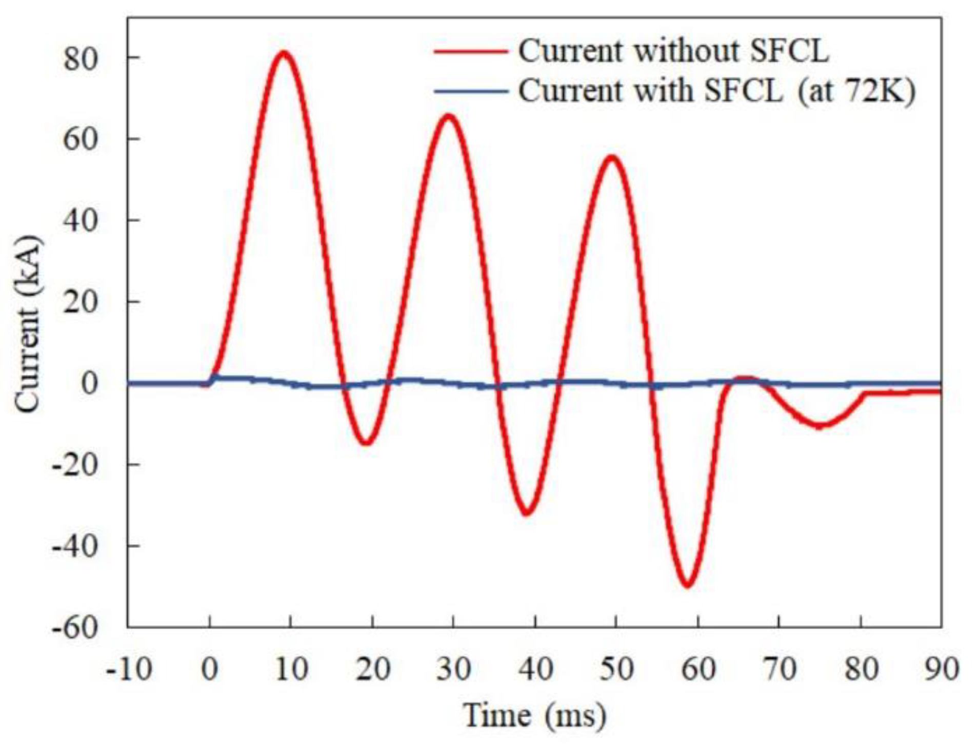
3.4. Fault Current Limiting Tests
4. Test Results
4.1. Limiting Performance
4.2. Response Time
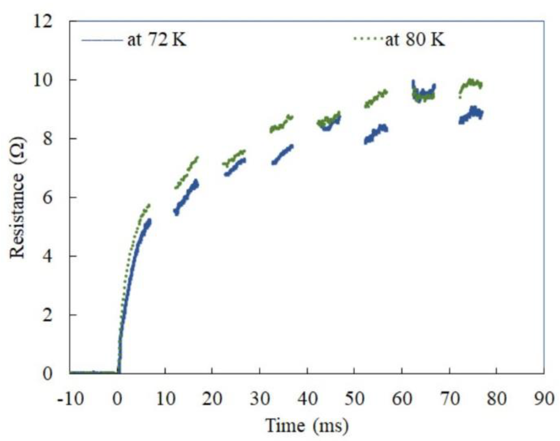
4.3. Limiter Resistance
4.4. Power
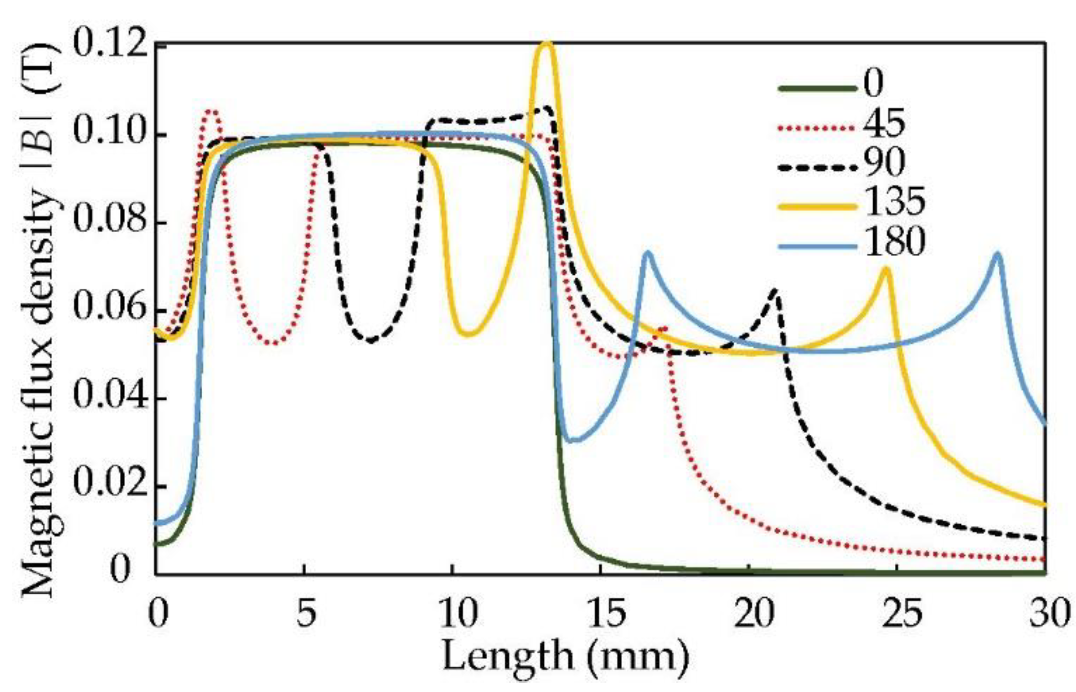
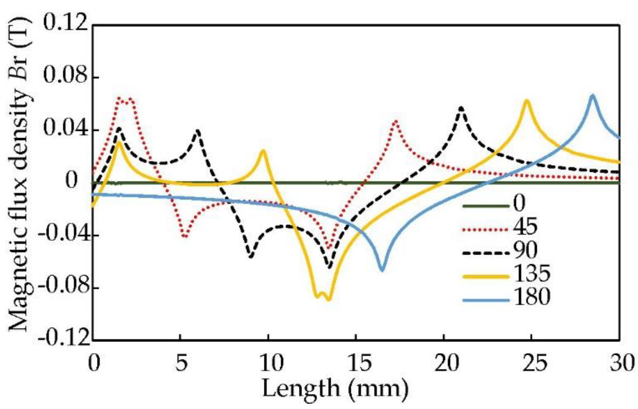
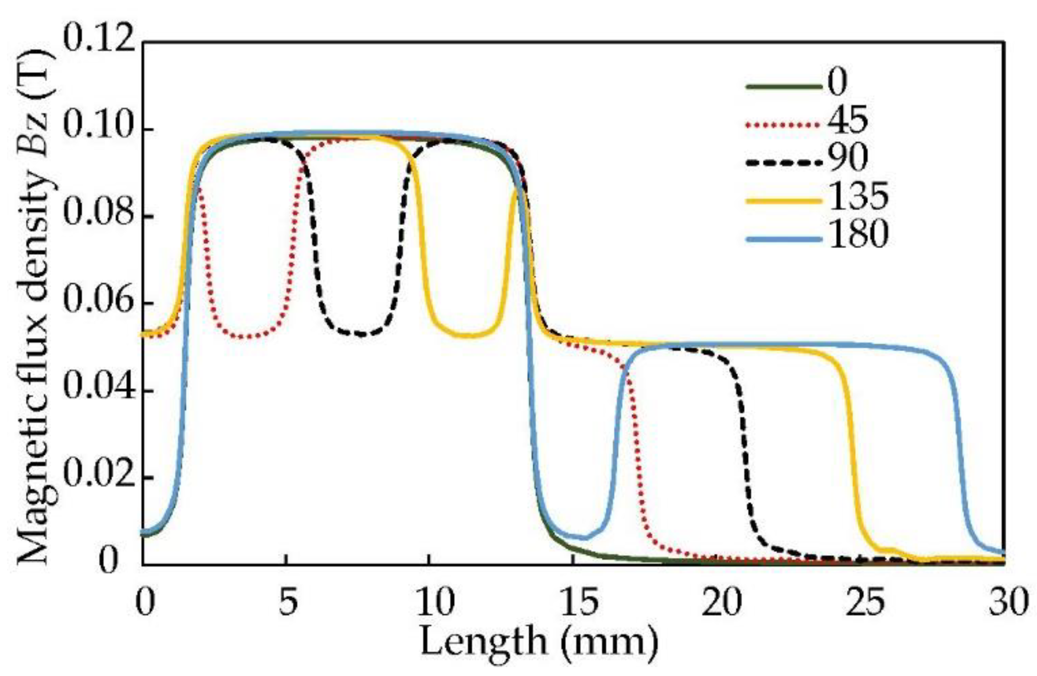
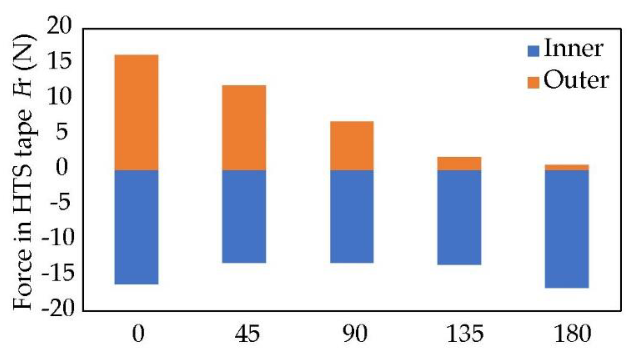
5. Forces and Stresses
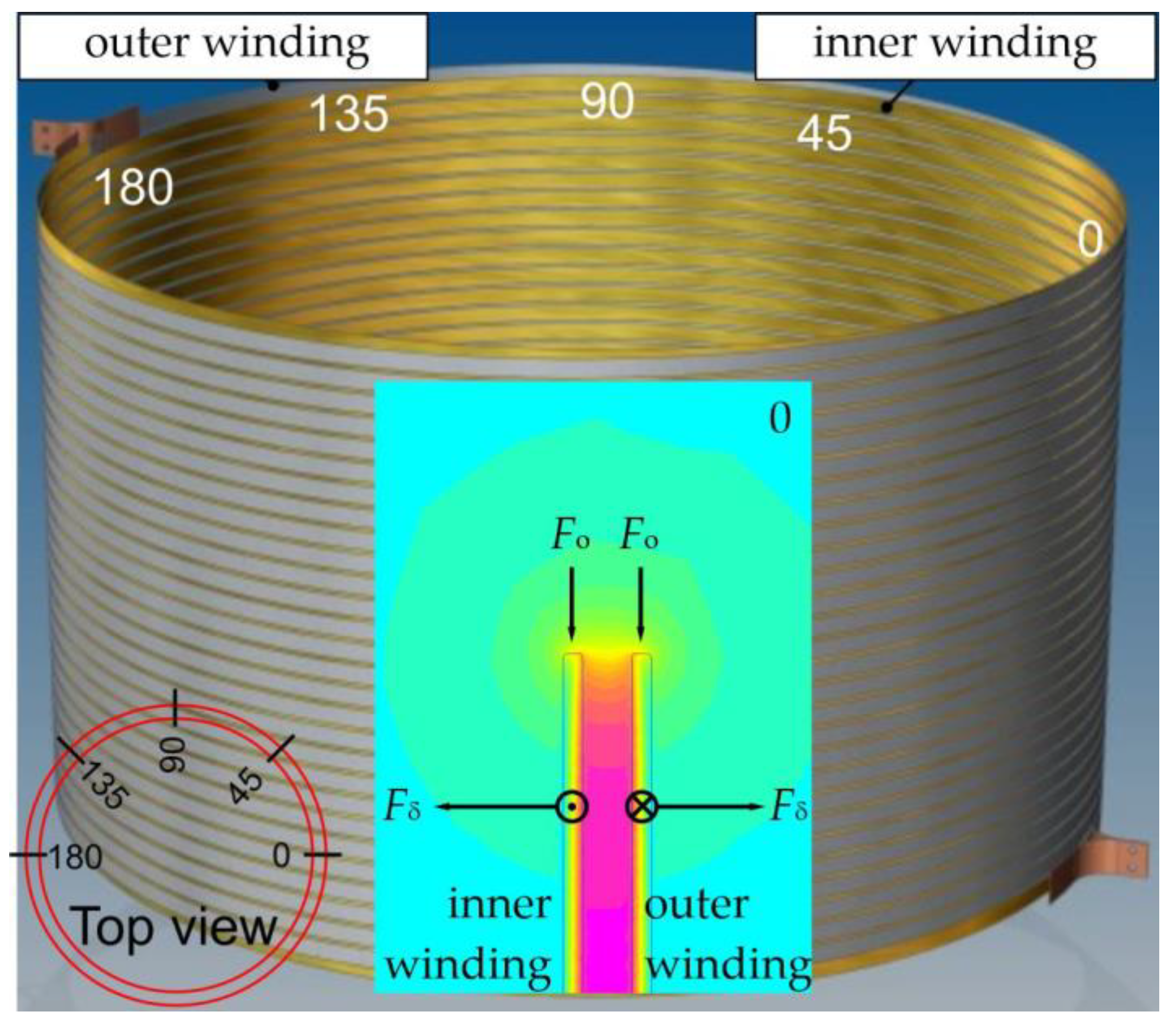
5.1. Forces Acting on Windings
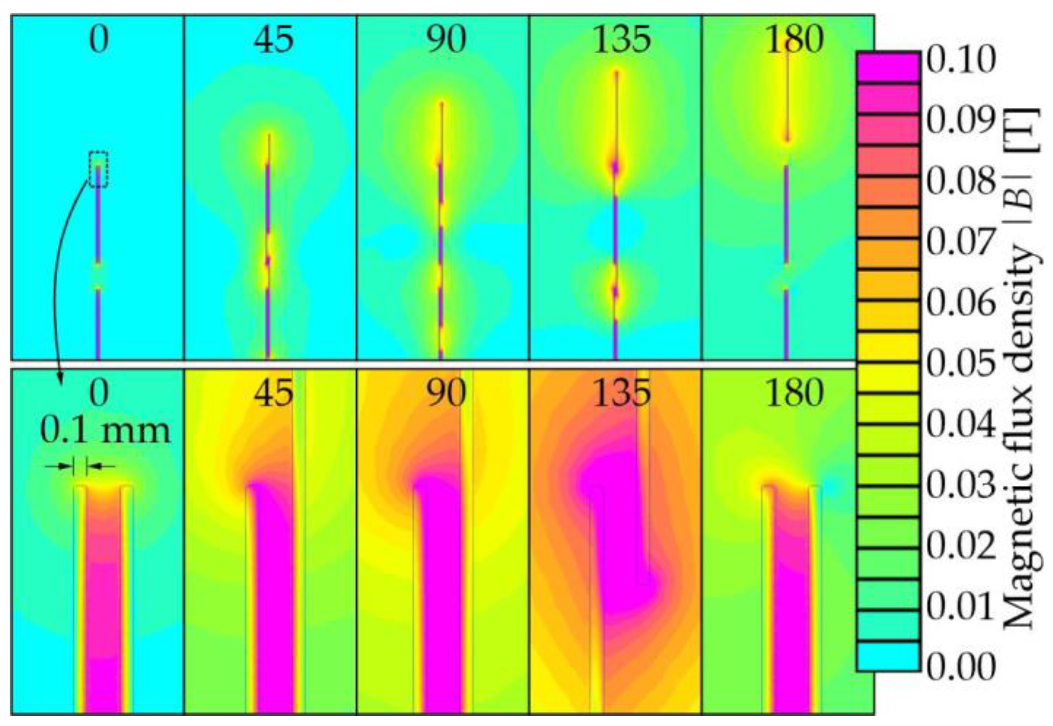
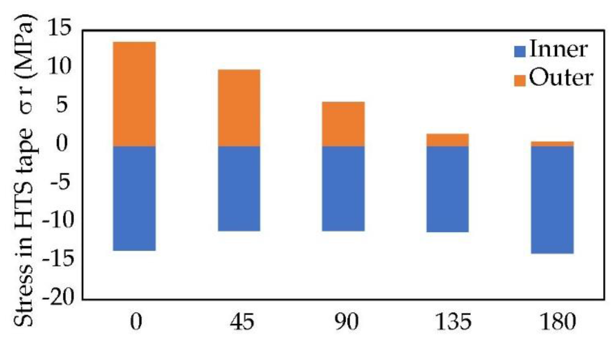
5.2. Radial Forces
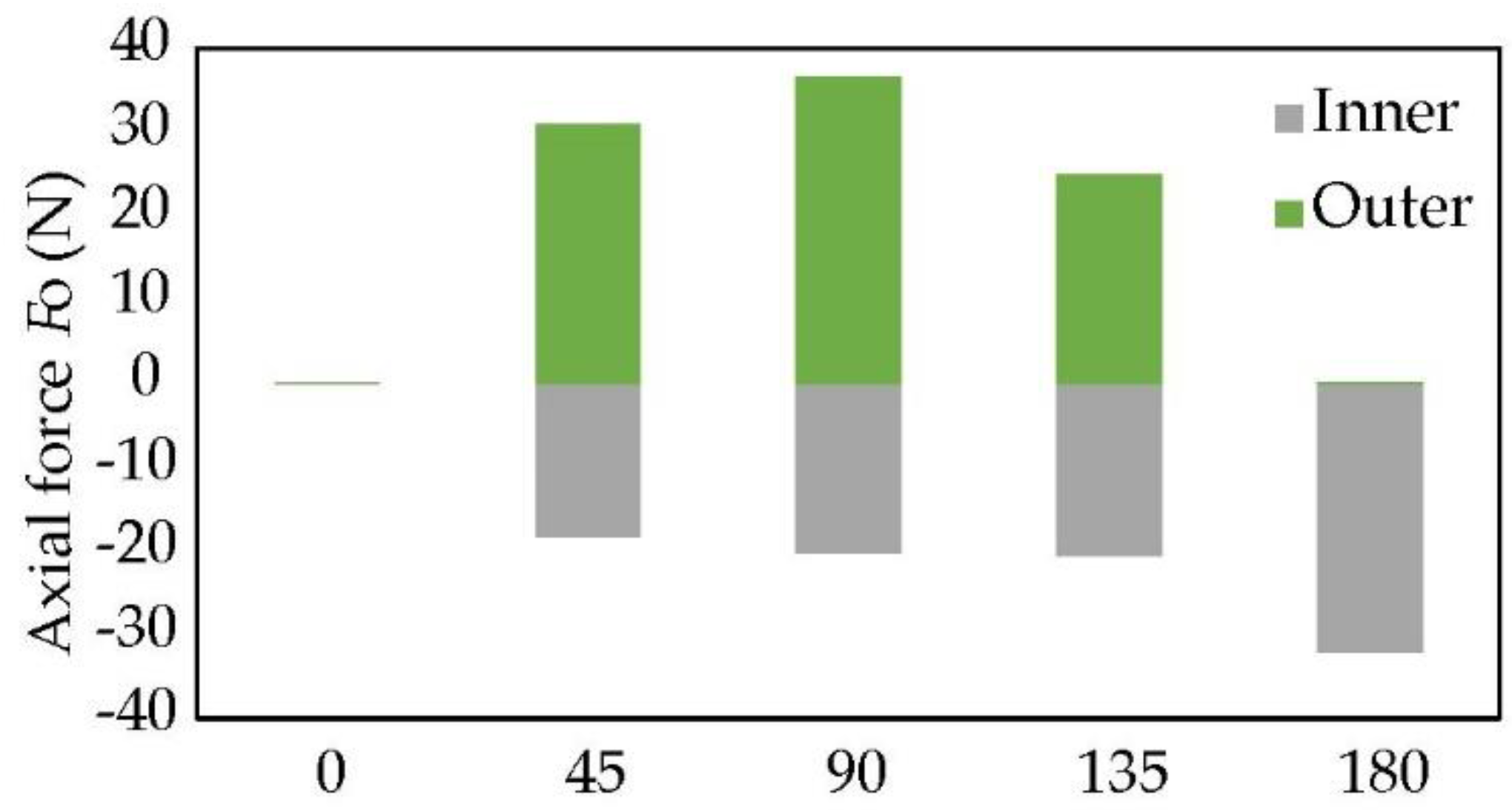
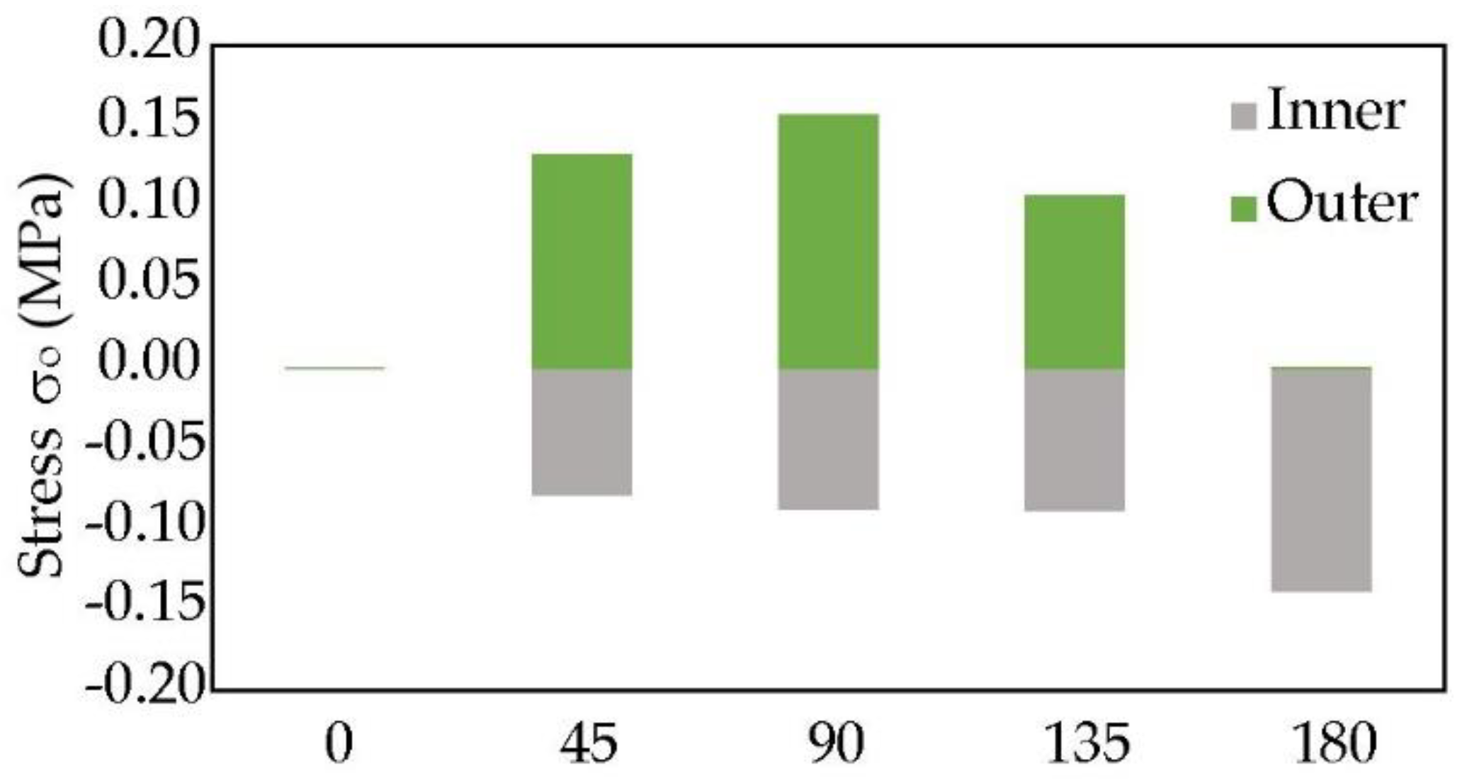
5.3. Axial Forces
6. Conclusions
Funding
Institutional Review Board Statement
Informed Consent Statement
Data Availability Statement
Conflicts of Interest
References
- Kozak, J.; Majka, M.; Kozak, S. Experimental Results of a 15 kV, 140 A Superconducting Fault Current Limiter. IEEE Trans. Appl. Supercond. 2017, 27, 5600504. [Google Scholar] [CrossRef]
- Kozak, J.; Majka, M.; Blazejczyk, T.; Berowski, P. Tests of the 15-kV Class Coreless Superconducting Fault Current Limiter. IEEE Trans. Appl. Supercond. 2016, 26, 5600804. [Google Scholar] [CrossRef]
- Majka, M.; Kozak, J.; Kozak, S.; Wojtasiewicz, G.; Janowski, T. Design and Numerical Analysis of the 15 kV Class Coreless Inductive Type SFCL. IEEE Trans. Appl. Supercond. 2014, 25, 5601005. [Google Scholar] [CrossRef]
- Kozak, J.; Majka, M.; Janowski, T.; Kozak, S.; Wojtasiewicz, G.; Kondratowicz-Kucewicz, B. Tests and Performance Analysis of Coreless Inductive HTS Fault Current Limiters. IEEE Trans. Appl. Supercond. 2011, 21, 1303–1306. [Google Scholar] [CrossRef]
- Naeckel, O.; Noe, M. Design and Test of an Air Coil Superconducting Fault Current Limiter Demonstrator. IEEE Trans. Appl. Supercond. 2013, 24, 5601605. [Google Scholar] [CrossRef]
- Kado, H.; Ickikawa, M. Performance of a high-Tc superconducting fault current limiter-design of a 6.6 kV magnetic shielding type superconducting fault current limiter. IEEE Trans. Appl. Supercond. 1997, 7, 993–996. [Google Scholar] [CrossRef]
- Heydari, H.; Abrishami, A.A.; Bidgoli, M.M. Comprehensive Analysis for Magnetic Shield Superconducting Fault Current Limiters. IEEE Trans. Appl. Supercond. 2013, 23, 5604610. [Google Scholar] [CrossRef]
- Nackel, O.; Noe, M. Conceptual Design Study of an Air Coil Fault Current Limiter. IEEE Trans. Appl. Supercond. 2012, 23, 5602404. [Google Scholar] [CrossRef]
- Heydari, H.; Sharifi, R. Three-Dimensional Pareto-Optimal Design of Inductive Superconducting Fault Current Limiters. IEEE Trans. Appl. Supercond. 2010, 20, 2301–2311. [Google Scholar] [CrossRef]
- Sharifi, R.; Heydari, H. Viable Inductive Superconducting Fault-Current Limiters Using Autotransformer-Based Hybrid Schemes. IEEE Trans. Appl. Supercond. 2011, 21, 3514–3522. [Google Scholar] [CrossRef]
- Jingye, Z.; Dai, S.; Wang, Z.; Zhang, D.; Zhang, Z.; Zhang, F.; Xu, Z.; Zhu, Z.; Zhang, G.; Xu, X.; et al. Design, fabrication, and tests of three HTS coils for a model fault current limiter. IEEE Trans. Appl. Super-Cond. 2010, 20, 1135–1138. [Google Scholar] [CrossRef]
- Kozak, J.; Majka, M.; Kozak, S.; Janowski, T. Design and Tests of Coreless Inductive Superconducting Fault Current Limiter. IEEE Trans. Appl. Supercond. 2012, 22, 5601804. [Google Scholar] [CrossRef]
- Hekmati, A.; Hosseini, M.; Vakilian, M.; Fardmanesh, M. A novel method of flat YBCO rings development for shield-type superconducting fault current limiters fabrication. Phys. C Supercond. 2012, 472, 39–43. [Google Scholar] [CrossRef]
- Kvitkovic, J.; Pamidi, S.V.; Graber, L.; Chiocchio, T.; Steurer, M.; Usoskin, A. AC loss and magnetic shielding measurements on 2G HTS inductive fault current limiter prototype modules. IEEE Trans. Appl. Supercond. 2014, 24, 5600604. [Google Scholar] [CrossRef]
- de Sousa, W.T.B.; Nackel, O.; Noe, M. Transient Simulations of an Air-Coil SFCL. IEEE Trans. Appl. Supercond. 2014, 24, 5601807. [Google Scholar] [CrossRef]
- Kozak, J.; Majka, M.; Janowski, T.; Kozak, S. Superconducting coreless inductive fault current limiter for medium-voltage systems. Prz. Elektrotech. 2012, 88, 245–248. [Google Scholar]
- Kozak, J.; Majka, M.; Janowski, T.; Kozak, S. Design and Development of the First Polish Superconducting Fault Current Limiter For MV Distribution Systems. Phys. Procedia 2012, 36, 845–848. [Google Scholar] [CrossRef]
- Majka, M.; Kozak, J.; Janowski, T.; Kozak, S. Performance analysis of coreless inductive superconducting fault current limiters made of the first and second generation HTS tape. Prz. Elektrotech. 2012, 88, 32–35. [Google Scholar]
- Li, B.; Wang, C.; Wei, Z.; Xin, Y.; Li, B.; He, J. Technical Requirements of the DC Superconducting Fault Current Limiter. IEEE Trans. Appl. Supercond. 2018, 28, 5602805. [Google Scholar] [CrossRef]
- Hong, H.; Su, B.; Niu, G.J.; Cui, J.B.; Tian, B.; Li, Q.; Wang, L.Z.; Wang, Z.H.; Zhang, K.; Xin, Y. Design, fabrication, and operation of the cryogenic system for a 220 kV/300 MVA saturated iron-core su-perconducting fault current limiter. IEEE Trans. Appl. Supercond. 2014, 24, 9002204. [Google Scholar] [CrossRef]
- Li, B.; Jing, F.; Li, B.; Chen, X.; Jia, J. Study of the Application of Active Saturated Iron-Core Superconductive Fault Current Limiters in the VSC-HVDC System. IEEE Trans. Appl. Supercond. 2018, 28, 5602906. [Google Scholar] [CrossRef]
- Ma, T.; Dai, S.; Song, M.; Li, C. Electromagnetic Design of High-Temperature Superconducting DC Bias Winding for Single-Phase 500 kV Saturated Iron-Core Fault Current Limiter. IEEE Trans. Appl. Supercond. 2017, 28, 5200805. [Google Scholar] [CrossRef]
- Noe, M.; Hobl, A.; Tixador, P.; Martini, L.; Dutoit, B. Conceptual Design of a 24 kV, 1 kA Resistive Superconducting Fault Current Limiter. IEEE Trans. Appl. Supercond. 2011, 22, 5600304. [Google Scholar] [CrossRef]
- Yan, S.; Tang, Y.; Ren, L.; Xu, Y.; Wang, Z.; Liang, S.; Zhang, Z. Design and Verification Test of a Flux-Coupling-Type Superconducting Fault Current Limiter. IEEE Trans. Magn. 2018, 24, 9000105. [Google Scholar] [CrossRef]
- Han, T.-H.; Ko, S.-C.; Lim, S.-H.; Ko, S.-C. Fault Current Limiting Characteristics of Transformer-Type Superconducting Fault Current Limiter Due to Winding Direction of Additional Circuit. IEEE Trans. Appl. Supercond. 2018, 28, 5601906. [Google Scholar] [CrossRef]
- Kozak, J.; Majka, M.; Kozak, S.; Janowski, T. Comparison of Inductive and Resistive SFCL. IEEE Trans. Appl. Supercond. 2012, 23, 5600604. [Google Scholar] [CrossRef]
- Didier, G.; Bonnard, C.; Lubin, T.; Lévêque, J. Comparison between inductive and resistive SFCL in terms of current limitation and power system transient stability. Electr. Power Syst. Res. 2015, 125, 150–158. [Google Scholar] [CrossRef]
- Morandi, A. State of the art of superconducting fault current limiters and their application to the electric power system. Phys. C Supercond. 2013, 484, 242–247. [Google Scholar] [CrossRef]
- Kempski, A.; Rusinski, J. A study of the Superconducting Fault Current Limiter application in a MV network with distributed energy sources. In Proceedings of the 2017 Progress in Applied Electrical Engineering (PAEE), Koscielisko, Poland, 25–30 June 2017. [Google Scholar]
- Rebizant, W.; Solak, K.; Brusilowicz, B.; Benysek, G.; Kempski, A.; Rusiński, J. Coordination of overcurrent protection relays in networks with superconducting fault current limiters. Int. J. Electr. Power Energy Syst. 2018, 95, 307–314. [Google Scholar] [CrossRef]
- Hayakawa, N.; Maeno, Y.; Kojima, H. Fault Current Limitation Coordination in Electric Power Grid with Superconducting Fault Current Limiters. IEEE Trans. Appl. Supercond. 2018, 28, 5602304. [Google Scholar] [CrossRef]
- Rusiński, J. Impact of superconducting fault current limiter on the distributed energy source work. IET Gener. Transm. Distrib. 2017, 12, 310–317. [Google Scholar] [CrossRef]
- Olejnik, B. Adaptive Zero-Sequence Overcurrent Criterion for Earth Fault Detection for Fault Current Passage Indicators in Resistor Grounded Medium Voltage Networks. IEEE Access 2021, 9, 63952–63965. [Google Scholar] [CrossRef]
- Xu, Z.; Li, X.; Stojanovic, V. Exponential stability of nonlinear state-dependent delayed impulsive systems with appli-cations. Nonlinear Anal. Hybrid Syst. 2021, 42, 101088. [Google Scholar] [CrossRef]
- Zhang, X.; Wang, H.; Stojanovic, V.; Cheng, P.; He, S.; Luan, X.; Liu, F. Asynchronous Fault Detection for Interval Type-2 Fuzzy Nonhomogeneous Higher Level Markov Jump Systems With Uncertain Transition Probabilities. IEEE Trans. Fuzzy Syst. 2021, 30, 2487–2499. [Google Scholar] [CrossRef]
- Tsotsopoulou, E.; Karagiannis, X.; Papadopoulos, P.; Dysko, A.; Yazdani-Asrami, M.; Booth, C.; Tzelepis, D. Time-Domain Protection of Superconducting Cables Based on Artificial Intelligence Classifiers. IEEE Access 2022, 10, 10124–10138. [Google Scholar] [CrossRef]
- García, G.; Marene Larruskain, D.; Etxegarai, A. Modelling of Resistive Type Superconducting Fault Current Limiter for HVDC Grids. Energies 2022, 15, 4605. [Google Scholar] [CrossRef]
- Kozak, J.; Majka, M.; Kozak, S. Design Considerations on a Resistive Superconducting Fault Current Limiter. Acta Phys. Pol. A 2020, 138, 710–714. [Google Scholar] [CrossRef]
- Kozak, S. Superconducting Surge Current Limiter. Energies 2021, 14, 6944. [Google Scholar] [CrossRef]
- Data from Superpower Inc. Available online: https://superpower-inc.com (accessed on 30 July 2022).


| Parameter | Value | |
|---|---|---|
| Nominal voltage | UN | 6 kV |
| Nominal current | IN | 140 A |
| Overload current | IOverload | 420 A |
| Voltage on the limiter @ IN | USCFL | 0.2 V |
| Voltage on the limiter @ IOverload | USCFLOverload | 0.6 V |
| Prospective peak current | ipeak | 81 kA |
| First peak limiting | ip | 1.9 kA |
| Limitation time | tlim | 80 ms |
| Response time of the surge current limitation | tresponse | 0.6 ms |
| Operating temperature | T | 72 K |
| Cryostat height | H | 1 m |
| Cryostat diameter | O.D. | 0.87 m |
| Weight | m | 340 kg |
Publisher’s Note: MDPI stays neutral with regard to jurisdictional claims in published maps and institutional affiliations. |
© 2022 by the author. Licensee MDPI, Basel, Switzerland. This article is an open access article distributed under the terms and conditions of the Creative Commons Attribution (CC BY) license (https://creativecommons.org/licenses/by/4.0/).
Share and Cite
Kozak, J. Forces and Stresses in the Windings of a Superconducting Fault Current Limiter. Energies 2022, 15, 6519. https://doi.org/10.3390/en15186519
Kozak J. Forces and Stresses in the Windings of a Superconducting Fault Current Limiter. Energies. 2022; 15(18):6519. https://doi.org/10.3390/en15186519
Chicago/Turabian StyleKozak, Janusz. 2022. "Forces and Stresses in the Windings of a Superconducting Fault Current Limiter" Energies 15, no. 18: 6519. https://doi.org/10.3390/en15186519
APA StyleKozak, J. (2022). Forces and Stresses in the Windings of a Superconducting Fault Current Limiter. Energies, 15(18), 6519. https://doi.org/10.3390/en15186519