Article

Investigation on Flow Maldistribution and Thermo-Hydraulic Performance of PCHEs with Spoiler Perforated Boards

1
School of Energy Science and Engineering, Harbin Institute of Technology, Harbin 150001, China
2
School of Environment, Harbin Institute of Technology, Harbin 150001, China
3
State Key Laboratory of Advanced Welding and Joining, Harbin Institute of Technology, Harbin 150001, China
*
Author to whom correspondence should be addressed.
Energies 2022, 15(18), 6518; https://doi.org/10.3390/en15186518
Submission received: 12 August 2022 / Revised: 31 August 2022 / Accepted: 2 September 2022 / Published: 6 September 2022
(This article belongs to the Special Issue Numerical Simulation on Heat Transfer Technique)

Abstract

:
In this study, the effects of the maldistribution coefficient on the thermo-hydraulic performance of discontinuous fin printed circuit heat exchanger (DF-PCHE) entrance head and channels are numerically investigated. To improve the flow uniformity at the entrance head, the flow in the exchanger with three types of spoiler perforated boards (SPBs) having 3 × 3, 4 × 4, and 5 × 5 holes and three kinds of hole diameters (Φd = 30, 25, and 20 mm), respectively, are compared to the flow in an exchanger with no SPB. The results show that a small maldistribution coefficient for the inlet velocity field is beneficial for the thermo-hydraulic performance of the DF-PCHE channels, and a maldistribution coefficient of 0.7 is an acceptable velocity distribution for the PCHE channel inlet. Using the 3 × 3 SPB with Φd = 30 mm, the maldistribution coefficient becomes 0.7, the fastest among all the SPB application cases at ΔL = 150 mm. Moreover, its heat transfer coefficient and pressure drop increase by 22.46% and decreases by 47.2% compared to those of the exchanger without SPB, respectively.

1. Introduction

Printed circuit heat exchanger (PCHE) fabrication involves microchannel chemical etching and metal diffusion welding processes, i.e., PCHEs do not contain any joints, instead they possess welds that result in high stability performance under high-pressure and high-temperature working conditions [1,2]. In addition, owing to the large heat transfer coefficient and high specific surface area that is provided by the microchannels, PCHEs are more compact and light weight than traditional heat exchangers (HEs) [3]. Due to the aforementioned advantages, PCHEs have received increasing attention for application in many industrial fields, such as supercritical carbon dioxide systems [4], compressed gas energy storage [5], nuclear stations [6], liquified hydrogen, hydrogen refueling stations [7], liquified natural gas regasification, and cryogenic applications [8].
Despite their many advantages, PCHEs have two characteristics that are a cause of concern: a large pressure drop and nonuniform flow rates in the microchannel inlets. The large pressure drop that is mainly produced in the microchannels has been extensively investigated. It has been found that substitution of the traditional continuous fins (straight and zigzag fins) by discontinuous fins (DFs) (S-type and airfoil fins) is an effective method for reducing the pressure drop; four typical types of fins are shown in Figure 1 [9]. Tsuzuki et al. [10] first proposed a new discontinuous S-shaped fin, and found that an S-type fin channel has one-fifth the pressure drop of the conventional continuous zigzag fin channel with the same thermo-hydraulic performance. Kim et al. [11] first determined that using NACA-0020 airfoil fins (AFs) in PCHE channels reduces the pressure drop to one-twentieth of that of a zigzag channel while maintaining a similar heat transfer performance.
Due to the plenty of microchannel inlets for PCHE, as shown in Figure 2, the nonuniform flow is unavoidable. The flow tends to concentrate at the core channels; whereas the flow rates in the surrounding channels are very low. The maldistribution of the flow rate can cause an extremely large pressure drop at the core channels and little or no heat exchange in the surrounding channels. For the traditional tubular HEs, many studies have proven that improving the inlet maldistribution performance is advantageous for their thermo-hydraulic properties. Lalot et al. [12] experimentally determined that gross flow maldistribution leads to an effectiveness loss of approximately 7% for condensers and counterflow HEs and up to 25% for crossflow exchangers, for velocity ratios up to 15. Yang et al. [13] numerically studied the flow maldistribution for a parallel-plate fin HE, and demonstrated that a quasi-S header configuration is effective for improving HE performance. Wen et al. [14,15] found that using a baffle with three types of small holes in a plate fin HE can reduce the ratio of the maximum flow velocity to the minimum flow velocity from 3.44–3.04 to 1.57–1.68 for various Reynolds numbers. The improved header configuration could effectively improve the thermo-hydraulic performance of the HE. Habib et al. [16] numerically evaluated the flow maldistribution in an air-cooled HE. The results showed that reducing the nozzle diameter by 25% caused a 25% increase in the flow maldistribution. A reduction of 62.5% in the standard deviation of the mass flow rate inside the tubes was achieved by increasing the number of nozzles from two to four. Chu et al. [17] changed the shape of the entrance header of a straight-channel PCHE to improve the flow uniformity. They found that a streamline profile-modified hyperbolic inlet header can reduce the flow nonuniformity by 46% compared with the current practical manufactured model and simultaneously increase the overall performance of the PCHE by 39.5%. In summary, the aforementioned studies confirmed that improvement in the flow maldistribution is beneficial for the overall thermo-hydraulic performance of HEs.
In this study, the discontinuous fin PCHE was used for a micro gas turbine recuperator for extended-range electric vehicles. In order to satisfy the high requirements on heat transfer, pressure drop, and compactness simultaneously, the flow fields in the entrance head is optimized by a spoiler perforated board (SPB), which can improve the flow maldistribution in the entrance. There are three types of SPBs with 3 × 3, 4 × 4, and 5 × 5 holes and three kinds of hole diameters (Φd = 30, 25 and 20 mm) that are compared based on their ability to improve the overall performance of the PCHE. The velocity contours, heat transfer coefficient, and pressure drop are examined in detailed to clarify the mechanism of the flow features in the entrance head containing the SPB and the effect of the maldistribution coefficient on the thermo-hydraulic performance of the DF-PCHE.

2. Mathematical Approach

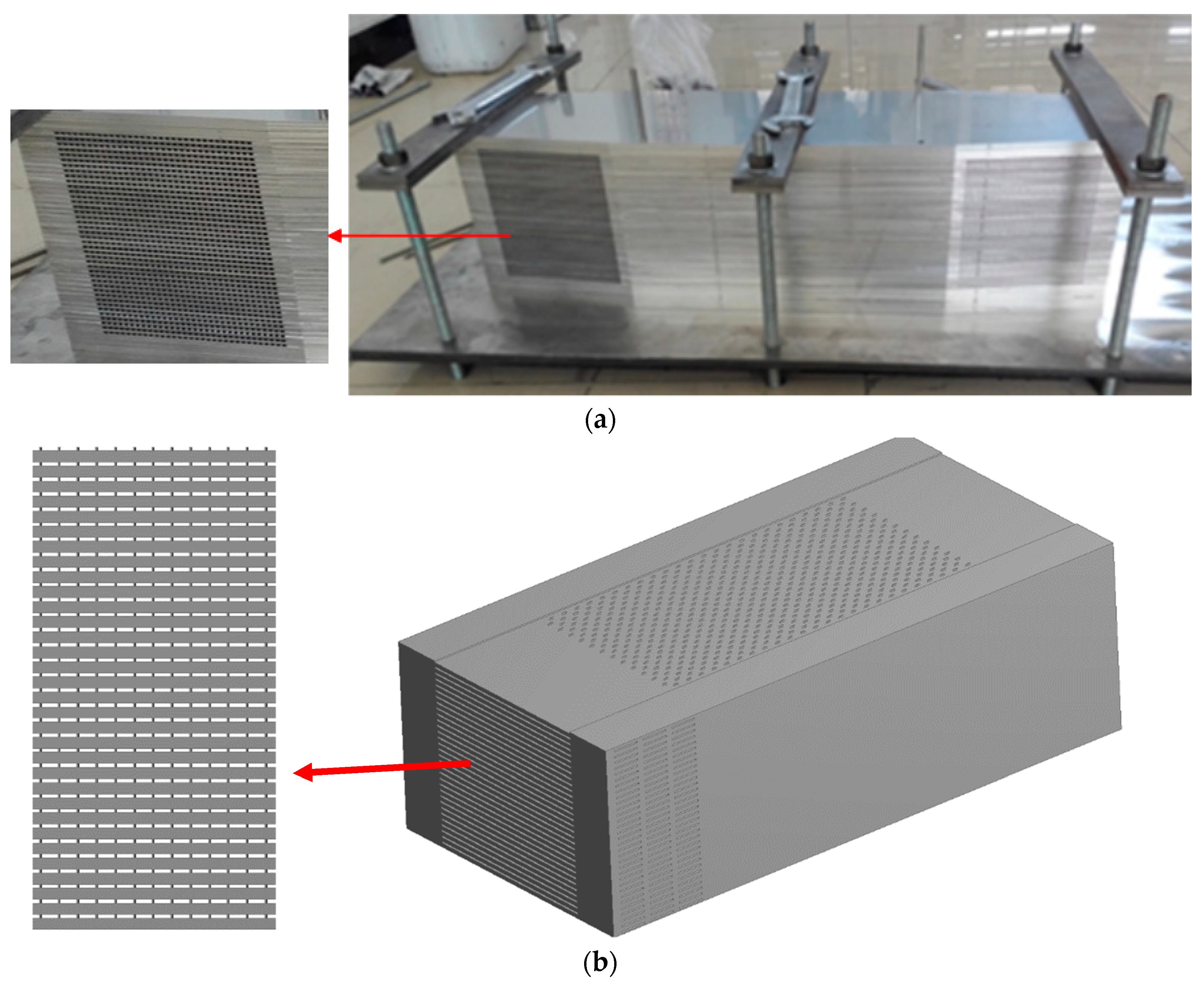
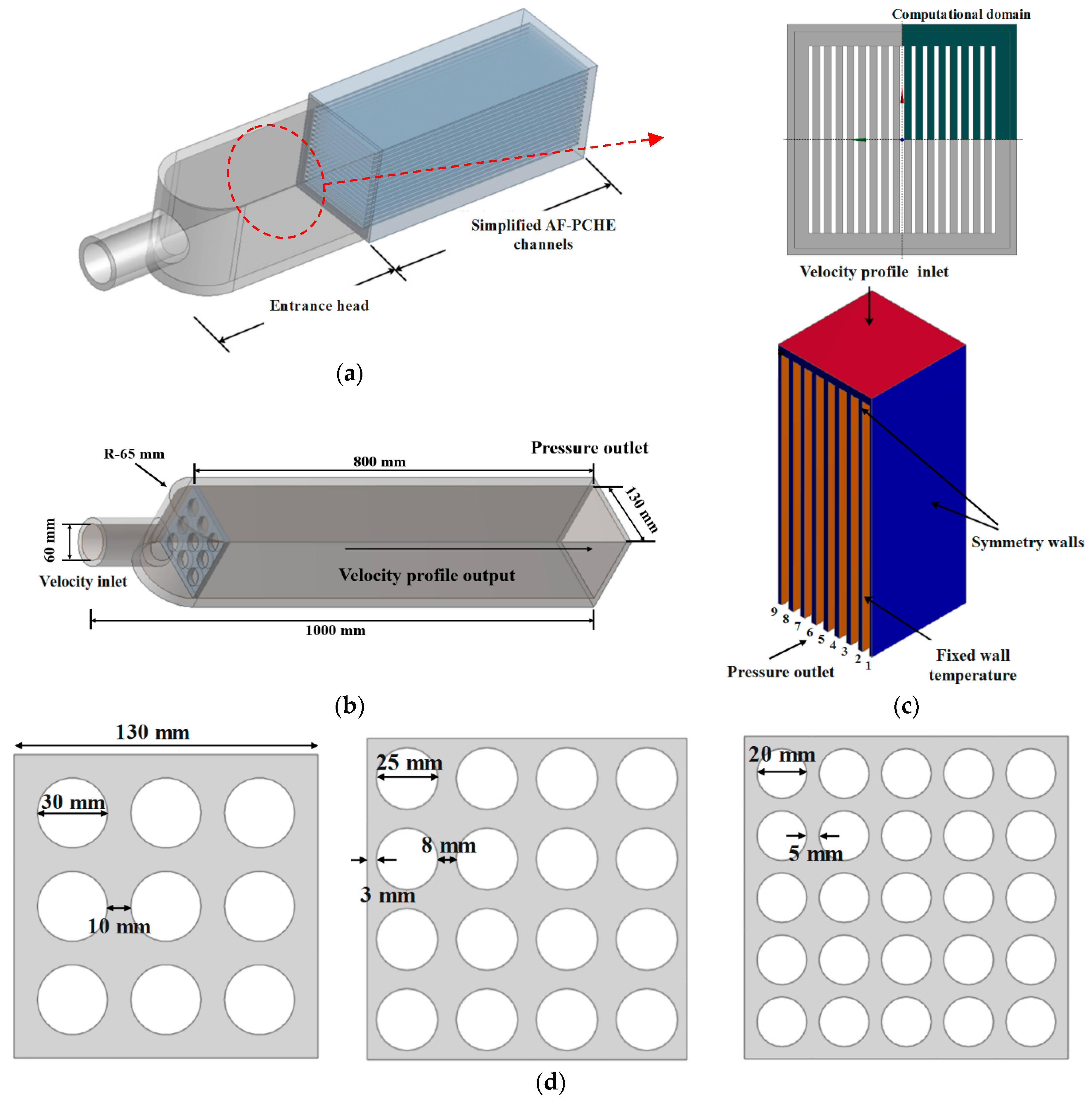
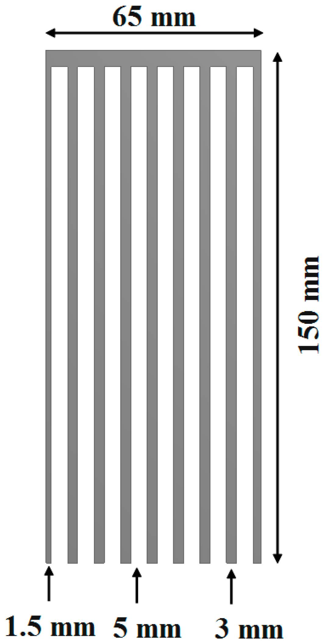
2.1. Physical Model and Boundary Conditions

In this study, the thermo-hydraulic performances of a PCHE entrance head and DF channels were numerically investigated separately, to simplify the model design and improve the calculation efficiency. In order to eliminate the effect of the coupling of the two parts, we take a long enough of entrance head, and extracted the velocity profiles of different cross sections. A complete schematic of the DF-PCHE entrance head and channels is shown in Figure 3a. An SPB was added in the entrance head to decrease the maldistribution of the flow fields; the DF channels were simplified as smooth plate channels without fins.
The computation domain and boundary conditions of the entrance head and the simplified DF-PCHE channels are shown in Figure 3b,c. The perforated board is arranged at the dotted line that is shown in Figure 3d. The entrance head has only a velocity inlet, a pressure outlet, and no-slip walls, without heat transfer. In addition, we select the velocity profiles at different cross-sections, and provide it to the velocity inlet of the DF-PCHE channels. For the channels, a quarter of the overall structure was selected as the computational domain, and the symmetry wall condition was set for the two internal cutting surfaces. The velocity profile inlet (Tin = 630 K) and pressure at the outlet of Pout = 0.15 MPa were employed, which is decided by the actual working condition of the micro gas turbine recuperator; the channel walls were set as fixed-temperature conditions (Twall = 650 K) because thermal boundaries have little effect on the turbulent heat transfer coefficient. Moreover, the two outside walls are considered to be in adiabatic conditions. The working fluid is micro gas turbine recuperator cold-side air, which is considered as incompressible; the thermal properties of the fluid only vary with temperature, as summarized in Table 1.
The structural parameters of the entrance head and the three types of SPBs are shown in Figure 3. The structural parameters of the DF-PCHE channels are shown in Figure 4.
An unstructured grid was used as the computational grid in the geometrical model. A grid refinement was performed near the walls, with the y plus less than 1, as shown in Figure 5. There are three types grids (2,730,000, 4,150,000, and 5,260,000) that are used for grids independence test, the α values for 3 × 3 SPB at ΔL = 100 mm are 1.393, 1.267, and 1.254, respectively. According to the α values results, the total number of grids is determined to be 4,150,000.

2.2. Governing Equations and Numerical Approach

In this study, the realizable k-ε model was employed [18,19], which is an improved version of the standard k-ε model, and has better substantial for complex channel prediction. The governing equations are as follows [20].
The continuity equation:
( ρ u i ) x i = 0
The momentum equation:
x j ( ρ u i u j ) = P x i + x j [ μ ( u i x j + u j x i 2 3 δ i j u j x j ) ] + x j ( ρ u i u j ¯ )
The energy equation:
x i [ u i ( ρ E + P ) ] = x i [ ( λ + c P μ t Pr t ) T x j + μ u i ( u i x j + u j x i 2 3 δ i j u j x j ) ]
where E is the total energy, E = C P T P / ρ + u 2 / 2 , and λ is the thermal conductivity.
The k equation:
x j ( ρ k u j ) = x j [ ( μ + μ t σ k ) k x j ] + G k ρ ε
The ε equation:
x j ( ρ ε u j ) = x j [ ( μ + μ t σ ε ) ε x j ] + ρ C 1 S ε ρ C 2 ε 2 k + ν ε
where Gk represents the production of the turbulent kinetic energy and is modeled as G k = μ t S 2 . μt represents the eddy viscosity and is modeled as μ t = ρ C μ k 2 / ε [21].
Moreover, C 1 = max [ 0.43 , η η + 5 ] , S = 2 S i j S i j , S i j = 1 2 ( u i x j + u j x i ) , C 2 = 1.9 , σ k = 1.2 , and σ ε = 1.2 [22].
The semi-implicit method for pressure-linked equations (SIMPLE) algorithm is used to solve the velocity and pressure equations, and the second-order upwind scheme is used for the energy and momentum equations. The scaled residuals for all the solutions should be less than 10−6 [23,24].

2.3. Data Reduction

The convective heat transfer coefficient (h), and pressure drop per unit length (ΔPL) are used to evaluate the heat transfer rate and pressure drop of the recuperator AF-PCHE entrance head and channels, respectively [25].
h = q T w a l l 0.5 ( T i n + T o u t )
Δ P L = Δ P / L
where q denotes the average heat flux, L denotes the channel length, and △P denotes the pressure drop between the inlet and the outlet. In addition, in this study, a maldistribution coefficient (α) is defined to represent the nonuniformity of the flow distribution in the different cross-sections. A large α implies a high nonuniformity degree, and α = 0 corresponds to a uniform flow.
α = ( | u l o c a l u a v e u a v e | ) d A c / A c
where ulocal is the local streamwise velocity value, uave is the average streamwise velocity value, and Ac denotes the cross-section area.

2.4. Numerical Model Validation

The present numerical model was validated using the experimental data of Ishizuka et al. [26]. The validation case uses a zigzag-type PCHE channel, with the hot side channel pitch pl = 9 mm, angle α = 115°, and a radius r = 0.95 mm, respectively, and the corresponding cold side values of 7.24 mm, 100°, and 0.9 mm, respectively. The working fluid on both sides is supercritical CO2, with a hot side inlet temperature, pressure, and mass flow rate of 553.05 K, 2.52 MPa, and 0.867 g/s, respectively, and the corresponding cold side values of 381.05 K, 8.28 Mpa, and 0.9456 g/s, respectively. The comparison of the experimental data and numerical results is summarized in Table 2. The maximum error is less than ±5%; the cold side error is larger than the hot side one.

3. Results and Discussion

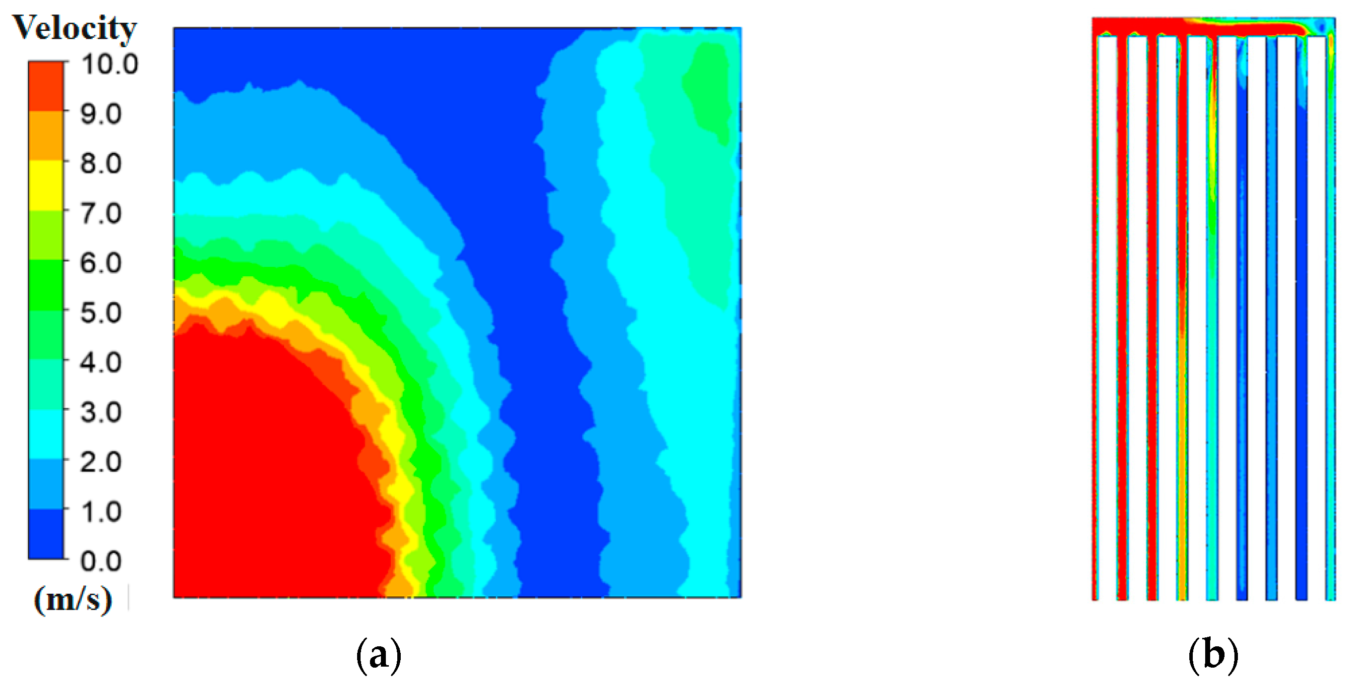
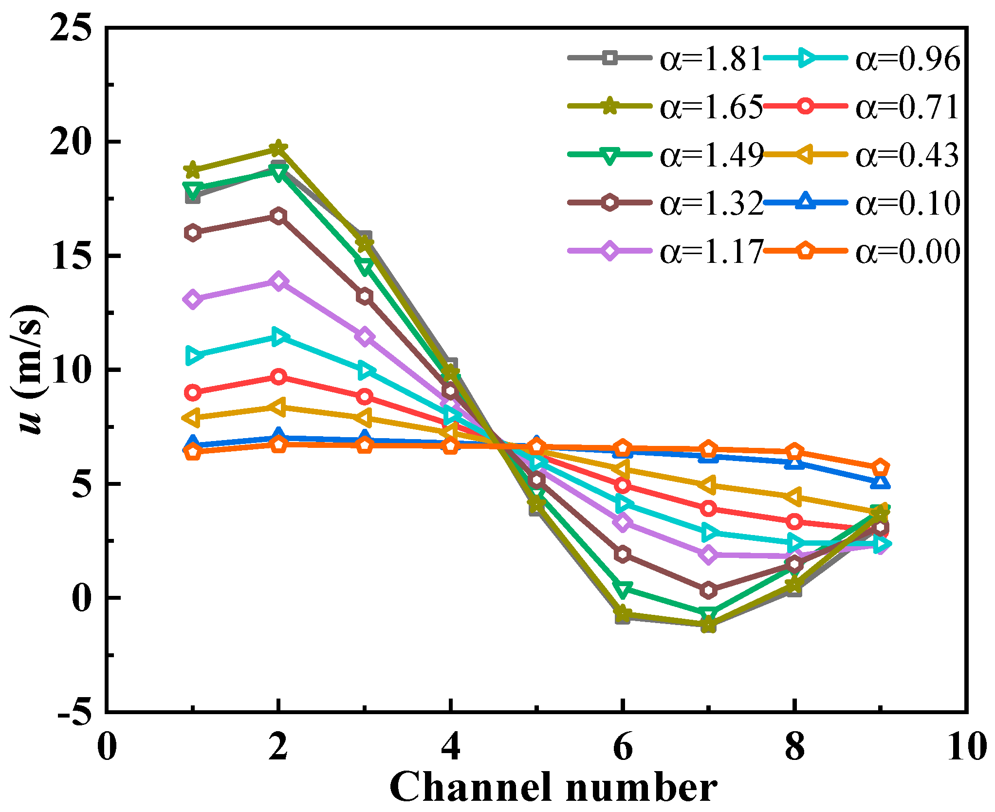
3.1. Thermo-Hydraulic Performance of DF-PCHE without SPBs

The flow distribution in the entrance head without SPBs and its five cross-sections are shown in Figure 6. The flow presents nonuniformity at the point where the entrance head abruptly expands and gradually becomes uniform with the increase in ΔL (distance between the current location and the SPB location). The α values are 1.81, 1.66, 1.24, 0.71, and 0.11 corresponding to ΔL = 100, 200, 300, 400, and 500 mm, showing that α declines rapidly when ΔL = 200–500 mm.
As examples, a quarter velocity profile at ΔL = 100 mm (α = 1.81) is shown in Figure 7a and the channel velocity distribution after imposing the velocity profile is displayed in Figure 7b. The red part velocity is the core of PCHE head. The up and right sides are the edge of PCHE head, which present a small velocity distribution that is caused by the flow field inhomogeneity. Notably, the flow rates are concentrated in the middle parts and the channels. This type of velocity profile inlet can mainly cause two disadvantages: an extremely large pressure drop at the middle channels, resulting in channel blockage, and an extremely low heat transfer rate of the surrounding channels and an ineffective heat transfer area.
The velocity distributions at the nine channels under different maldistribution coefficients are shown in Figure 8. Notably, a large α implies a significantly deteriorated uniformity. When α < 0.71, the uniformity at the nine channels is apparently acceptable. The heat transfer coefficient (h) and pressure drop (ΔPL) variations with the maldistribution coefficient (α) for the DF-PCHE channels without an SPB are shown in Figure 9. The results also indicate that when α > 0.7, h decreases, and ΔPL significantly increases with the increase in α; when α < 0.7, h decreases and ΔPL slightly increases with the increase in α. Therefore, ΔL = 400 mm (α = 0.71) can be selected as the fully developed length of the entrance head.

3.2. Thermo-Hydraulic Performance of DF-PCHE with SPBs

To shorten the fully developed length of the entrance head, an SPB is positioned in the entrance head; three types (3 × 3, 4 × 4, and 5 × 5) are compared. The flow distributions in the entrance heads with the three types of SPBs are shown in Figure 10. Notably, the flow in these entrance heads with SPBs tends to rapidly become uniform compared to the flow in the entrance head without an SPB (as Figure 6). The flow becomes nearly completely uniform at ΔL = 500, 400, 300, and 400 mm corresponding to the entrance heads with the 3 × 3, 4 × 4, and 5 × 5 SPBs, respectively.
The maldistribution coefficient (α) variations with ΔL for the four entrance heads that were studied are shown in Figure 11. The α values also present a significant decline with the SPBs. At ΔL = 100 mm, α decreases with an increase in perforations. In the ΔL = 100–175 mm range, α of the entrance head with the 3 × 3 SPB decreases most rapidly. This is because the secondary flow that is produced after 3 × 3 SPB is much larger than that after 4 × 4 and 5 × 5 SPB. Therefore, it causes a violent velocity fluctuation and α value variation. By contrast, in the ΔL = 175–300 mm range, α of the entrance head with the 4 × 4 SPB decreases most rapidly and its flow is the first to become completely uniform. The α values of the entrance heads with the 3 × 3 and 4 × 4 SPBs have two intersections at ΔL = 122 and 206 mm, respectively. In addition, the α values of the 5 × 5 SPB case are overall inferior to those of the entrance head with the 4 × 4 SPB.
Based on the results that were discussed in Section 3.1, α = 0.7 is an acceptable velocity profile for the DF-PECH inlet. The velocity profiles at ΔL = 150 mm for the four cases are extracted and applied to the DF-PECH inlet, because the entrance head with the 3 × 3 SPB at ΔL = 150 mm first reaches 0.7, as shown in Figure 11. The α values of the four cases at the ΔL = 150 mm cross-section and the corresponding thermos-hydraulic performance of the DF-PCHE channels are summarized in Table 3. H for the DF-PCHE channels with the 3 × 3, 4 × 4, and 5 × 5 SPBs increase by 22.46%, 18.72%, and 18.64%, respectively, compared to that of the channels without an SPB. The corresponding ΔPL decrease by 47.2%, 40.28%, and 39.63% compared to that of the channel without an SPB. The lowest α value of 0.7 (3 × 3 SPB) corresponds to the largest h and the lowest ΔPL, which can satisfy the thermo-hydraulic performance, size, and metal consumption requirements simultaneously.

3.3. Mechanism Analysis

The velocity contours at the SPB cross section (ΔL = 0) for the four cases are shown in Figure 12. Notably, the fluid is mainly concentrated at the center of the entrance head. The SPBs largely direct the fluid to the perforations, and mixing occurs after the fluid is sprayed from the SPBs. The 3 × 3 SPB case presents a significant flow around the perforations, whereas this flow is remarkably decreased with the 4 × 4 and 5 × 5 SPBs, which is a disadvantage for the uniform mixing of the fluid.
The streamlines of the entrance heads with the four types of SPBs in the longitudinal section are shown in Figure 13. They indicate that a long vortex zone is produced in the entrance head without an SPB, which is decreased after installation of the SPBs. The vortex zone length reaches 450, 210, 250, and 350 mm for the entrance heads without an SPB and with 3 × 3, 4 × 4, and 5 × 5 SPBs, respectively. This trend is explained as follows: a vortex flow is produced by each jet port, and with the increase in the perforations, the number of vortexes is also increased, causing a more chaotic flow field after the SPBs.

3.4. Effects of Hole Diameter on 3 × 3 SPB

There are three kinds of hole diameters (Φd = 30, 25 and 20 mm) of 3 × 3 SPBs that are compared. The velocity contours at SPB cross-section (ΔL = 0 and 150 mm) and longitudinal section are shown in Figure 14 and Figure 15. It is shown that with the decrease of hole diameters, the velocity magnitude at the holes increased significantly, which lead to a larger intensity of the secondary flow after the SPB, as shown in Figure 15. The velocity contours at cross-section (ΔL = 150 mm) also show that the maldistribution increases with the decrease in the hole diameter.
The thermo-hydraulic performance of the DF-PCHE channels with three kinds of hole diameter 3 × 3 SPBs using ΔL =150 mm cross-section as inlets are shown in Table 4. The results show that, the α values for Φd = 30 and 25 mm are nearly the same, which is obviously better than Φd = 20 mm. Besides, the thermal--hydraulic performance (h and ΔPL) of DF-PCHE channels for Φd = 30 mm is slightly better than that for Φd = 25 mm, and significantly better than that for Φd = 20 mm.

4. Conclusions

In this study, the thermo-hydraulic performances of a DF-PCHE entrance head and channels are numerically investigated. The effects of the maldistribution coefficient on the heat transfer performance and the pressure drop are examined in detail. To improve the uniformity in the entrance head, three types of SPBs (3 × 3, 4 × 4, and 5 × 5) and hole diameters (Φd = 30, 25, and 20 mm) are compared. The main conclusions are summarized as follows:
(1)
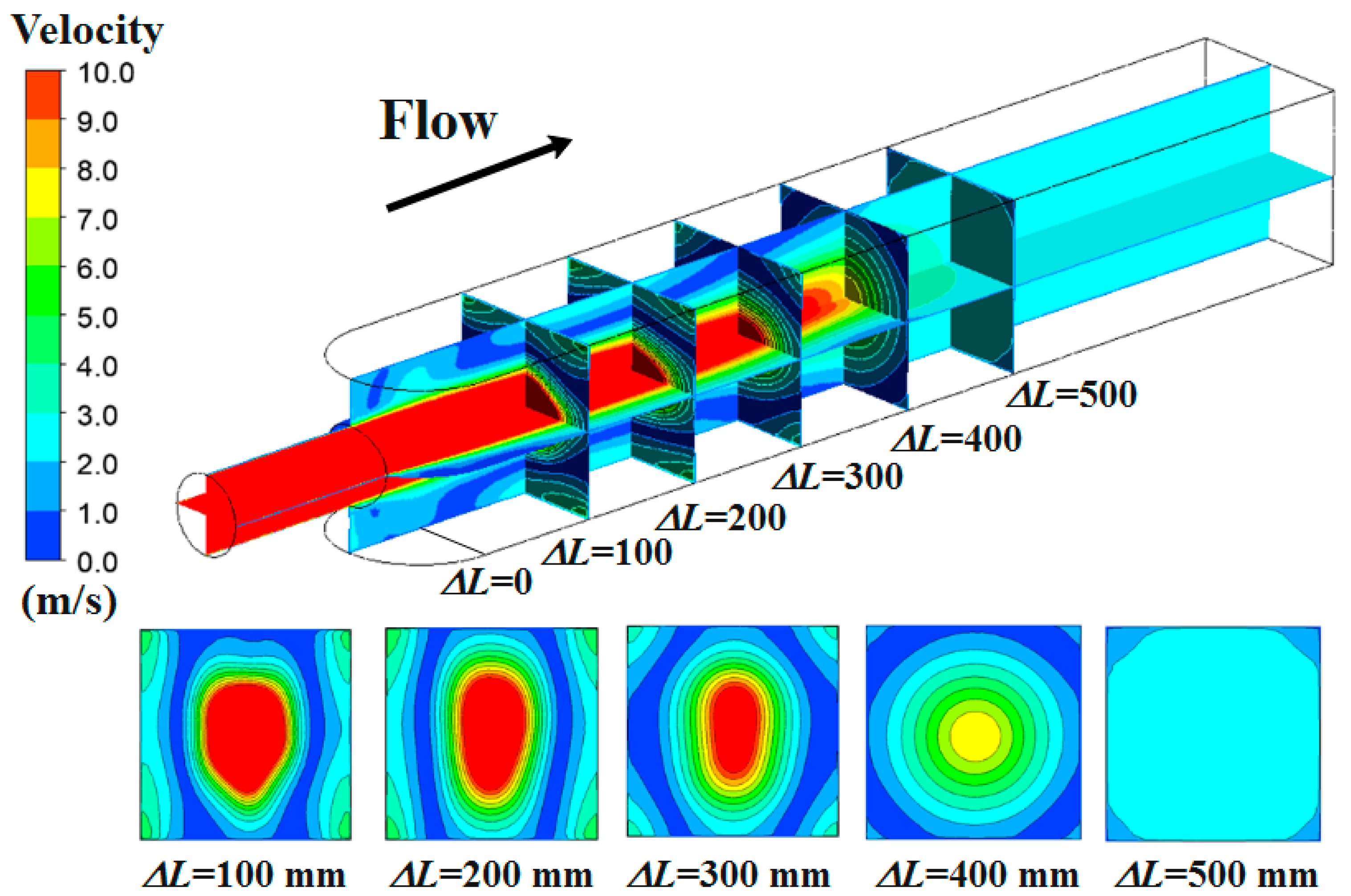
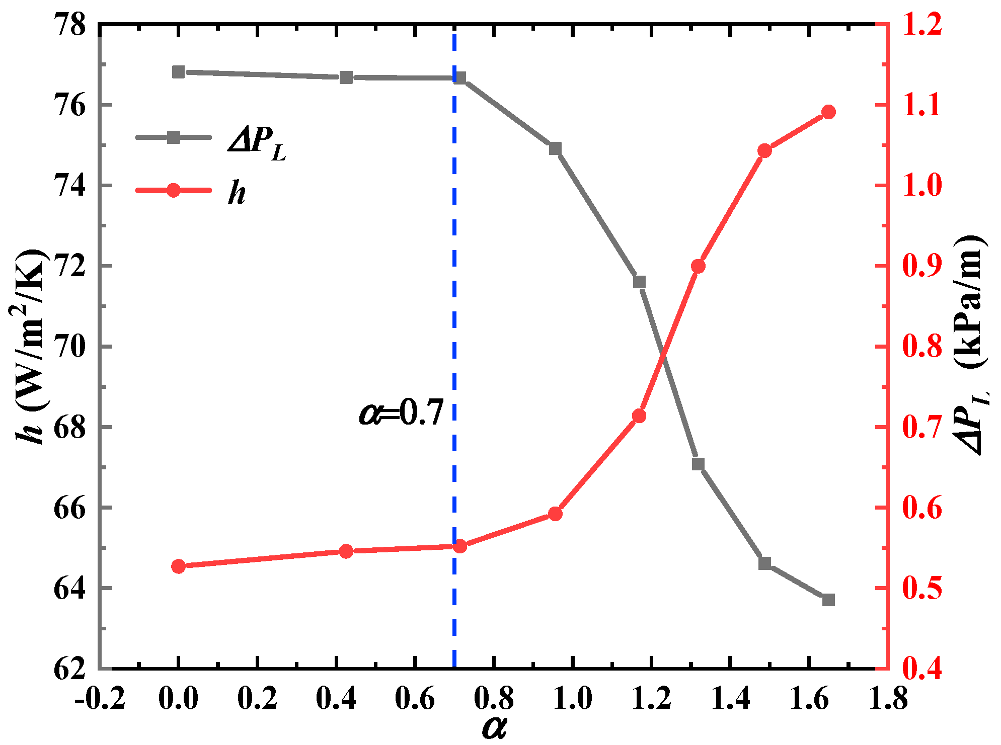
A small maldistribution coefficient (α) for the DF-PCHE channels inlet velocity field is beneficial for the heat transfer performance and the pressure drop; α = 0.7 is an acceptable velocity profile for the inlet.
(2)
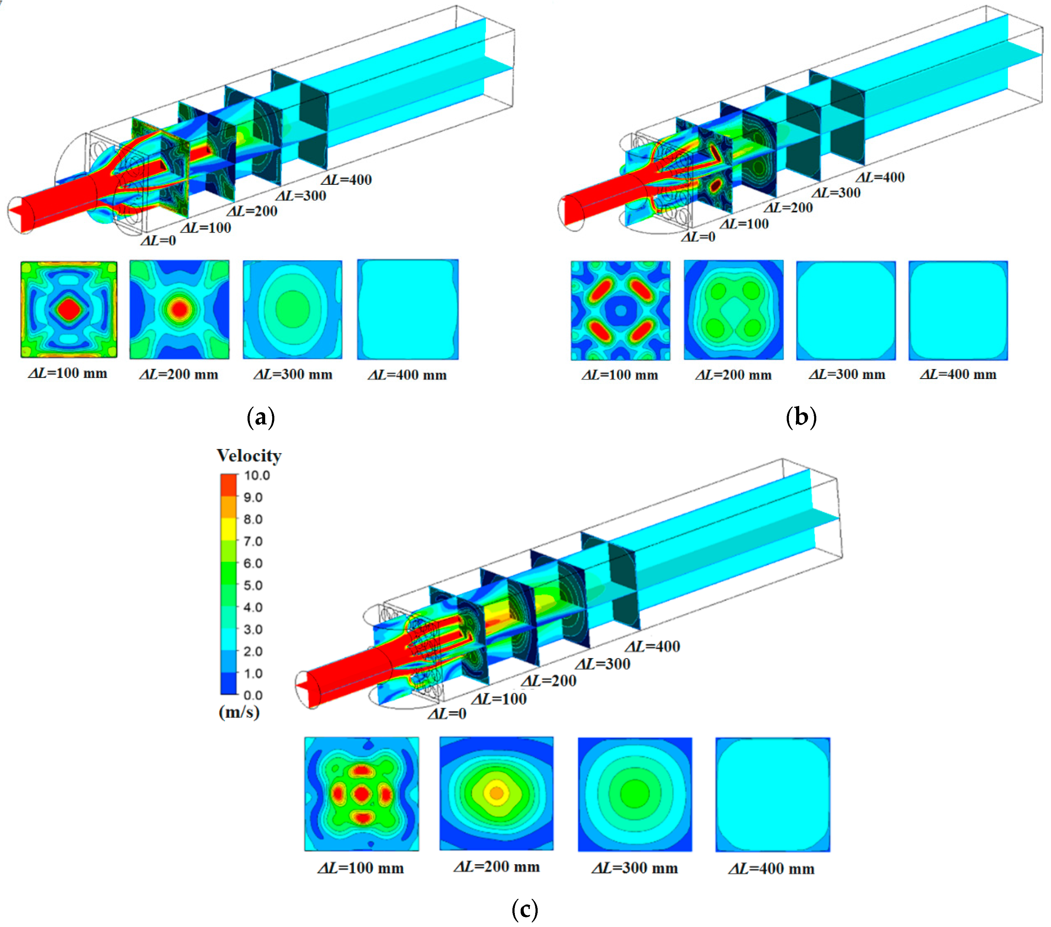
The SPBs rapidly decrease α for the velocity fields, and the 3 × 3 SPB causes α to first reach 0.7 among all the SPBs at ΔL = 150 mm.
(3)
Applying the velocity profile at the inlet, the h values for the 3 × 3, 4 × 4, and 5 × 5 SPB cases increase by 22.46%, 18.72%, and 18.64%, respectively, compared to that for the case without SPB. Moreover, their ΔPL values correspondingly decrease by 47.2%, 40.28%, and 39.63%, respectively, compared to that for the case without SPB.
(4)
The hole diameter Φd = 30 and 25mm are all acceptable, while the Φd = 20 mm causes larger secondary flow and poor thermo-hydraulic performances.

Author Contributions

Conceptualization, W.W. and B.L.; methodology, W.W. and Y.S.; software, W.W. and M.N.; validation, M.N.; formal analysis, W.W. and Y.T.; investigation, W.W.; resources, W.W.; data curation, W.W.; writing—original draft preparation, W.W.; writing—review and editing, W.W.; visualization, W.W.; supervision, W.W.; project administration, W.W.; funding acquisition, W.W. All authors have read and agreed to the published version of the manuscript.

Funding

This study is supported by National Natural Science Foundation of China (52106082), China Postdoctoral Science Foundation (2019M661279), Heilongjiang Provincial Postdoctoral Science Foundation (LBH-Z19162), and Heilongjiang Province Science and Technology Major Project (2020ZX10A03).

Informed Consent Statement

Not applicable.

Conflicts of Interest

The authors declare no conflict of interest.

Nomenclature

AcArea (m2)
C1, C2Realized k-ε model constants
CpSpecific heat capacity (J/kg/K)
DFDiscontinuous fins
EInternal energy (J/kg)
hHeat transfer coefficient (W/m2/K)
HEHeat exchanger
LLength (m)
TTemperature (K)
PPressure (Pa)
PCHEPrinted circuit heat exchanger
qHeat flux (W)
SPBSpoiler perforated board
u, v, wStreamwise, transverse, and vertical velocity component (m/s)
Greek letters
αMaldistribution coefficient
εTurbulence dissipation rate (m3/s2)
λThermal conductivity (W/m/K)
μDynamic viscosity (kg/m/s)
ρDensity of fluid (kg/m3)
ΦdHole diameter (mm)
Subscripts
in, outInlet and outlet
i, j, kDirections of the coordinate system
wallWall

References

  1. Kim, J.H.; Baek, S.; Jeong, S.; Jung, J. Hydraulic performance of a microchannel PCHE. Appl. Therm. Eng. 2010, 30, 2157–2162. [Google Scholar] [CrossRef]
  2. Wang, W.; Li, B.; Tan, Y.; Li, B.; Shuai, Y. Multi-objective optimal design of NACA airfoil fin PCHE recuperator for micro-gas turbine systems. Appl. Therm. Eng. 2022, 204, 117864. [Google Scholar] [CrossRef]
  3. Meshram, A.; Jaiswal, A.K.; Khivsara, S.D.; Ortega, J.D.; Ho, C.; Bapat, R.; Dutta, P. Modeling and analysis of a printed circuit heat exchanger for supercritical CO2 power cycle applications. Appl. Therm. Eng. 2016, 109, 861–870. [Google Scholar] [CrossRef]
  4. Xu, X.; Ma, T.; Li, L.; Zeng, M.; Chen, Y.; Huang, Y.; Wang, Q. Optimization of fin arrangement and channel configuration in an airfoil fin PCHE for supercritical CO2 cycle. Appl. Therm. Eng. 2014, 70, 867–875. [Google Scholar] [CrossRef]
  5. Huang, C.; Cai, W.; Wang, Y.; Liu, Y.; Li, Q.; Li, B. Review on the characteristics of flow and heat transfer in printed circuit heat exchangers. Appl. Therm. Eng. 2019, 153, 190–205. [Google Scholar] [CrossRef]
  6. Chen, M.; Sun, X.; Christensen, R.N.; Shi, S.; Skavdahl, I.; Utgikar, V.; Sabharwall, P. Experimental and numerical study of a printed circuit heat exchanger. Ann. Nucl. Energy 2016, 97, 221–231. [Google Scholar] [CrossRef]
  7. Chang, H.; Lian, J.; Ma, T.; Li, L.; Wang, Q. Design and optimization of an annular air-hydrogen precooler for advanced space launchers engines. Energy Convers. Manag. 2021, 241, 114279. [Google Scholar] [CrossRef]
  8. Pan, J.; Wang, J.; Tang, L.; Bai, J.; Li, R.; Lu, Y.; Wu, G. Numerical investigation on thermal-hydraulic performance of a printed circuit LNG vaporizer. Appl. Therm. Eng. 2020, 165, 114447. [Google Scholar] [CrossRef]
  9. Yoon, S.H.; No, H.C.; Kang, G.B. Assessment of straight, zigzag, S-shape, and airfoil PCHEs for intermediate heat exchangers of HTGRs and SFRs. Nucl. Eng. Des. 2014, 270, 334–343. [Google Scholar] [CrossRef]
  10. Tsuzuki, N.; Kato, Y.; Ishiduka, T. High performance printed circuit heat exchanger. Appl. Therm. Eng. 2007, 27, 1702–1707. [Google Scholar] [CrossRef]
  11. Kim, D.E.; Kim, M.H.; Cha, J.E.; Kim, S.O. Numerical investigation on thermal–hydraulic performance of new printed circuit heat exchanger model. Nucl. Eng. Des. 2008, 238, 3269–3276. [Google Scholar] [CrossRef]
  12. Lalot, P.F.S.; Lang, S.K.; Bergles, A.E. Flow maldistribution in heat exchangers. Appl. Therm. Eng. 1999, 19, 847–863. [Google Scholar] [CrossRef]
  13. Yang, H.; Wen, J.; Gu, X.; Liu, Y.; Wang, S.; Cai, W.; Li, Y. A mathematical model for flow maldistribution study in a parallel plate-fin heat exchanger. Appl. Therm. Eng. 2017, 121, 462–472. [Google Scholar] [CrossRef]
  14. Wen, J.; Li, Y. Study of flow distribution and its improvement on the header of plate-fin heat exchanger. Cryogenics 2004, 44, 823–831. [Google Scholar] [CrossRef]
  15. Wen, J.; Li, Y.; Zhou, A.; Zhang, K.; Wang, J. PIV experimental investigation of entrance configuration on flow maldistribution in plate-fin heat exchanger. Cryogenics 2006, 46, 37–48. [Google Scholar] [CrossRef]
  16. Habib, M.A.; Ben-Mansour, R.; Said, S.A.M.; Al-Qahtani, M.S.; Al-Bagawi, J.J.; Al-Mansour, K.M. Evaluation of flow maldistribution in air-cooled heat exchangers. Comput. Fluids 2009, 38, 677–690. [Google Scholar] [CrossRef]
  17. Chu, W.X.; Bennett, K.; Cheng, J.; Chen, Y.-T.; Wang, Q.-W. Numerical study on a novel hyperbolic inlet header in straight-channel printed circuit heat exchanger. Appl. Therm. Eng. 1999, 146, 805–814. [Google Scholar] [CrossRef]
  18. Fernández, I.; Sedano, L. Design analysis of a lead–lithium/supercritical CO2 Printed Circuit Heat Exchanger for primary power recovery. Fusion Eng. Des. 2013, 88, 2427–2430. [Google Scholar] [CrossRef]
  19. Wang, W.; Shuai, Y.; Li, B.; Li, B.; Lee, K.-S. Enhanced heat transfer performance for multi-tube heat exchangers with various tube arrangements. Int. J. Heat Mass Transf. 2021, 168, 120905. [Google Scholar] [CrossRef]
  20. ANSYS Inc. ANSYS Fluent Theory Guide; ANSYS Inc.: Canonsburg, PA, USA, 2011; Volume 15317, pp. 724–746. [Google Scholar]
  21. Shih, T.-H.; Liou, W.W.; Shabbir, A.; Yang, Z.; Zhu, J. A new k-ϵ eddy viscosity model for high reynolds number turbulent flows. Comput. Fluids 1995, 24, 227–238. [Google Scholar] [CrossRef]
  22. Malalasekere, W.; Versteeg, H.K. An Introduction to Computational Fluid Dynamics: The Finite Volume Method, 2nd ed.; Prentice Hall: Harlow, UK, 2007. [Google Scholar]
  23. Wang, W.; Zhang, Y.; Li, B.; Han, H.; Gao, X. Influence of geometrical parameters on turbulent flow and heat transfer characteristics in outward helically corrugated tubes. Energy Convers. Manag. 2017, 136, 294–306. [Google Scholar] [CrossRef]
  24. Chen, J.; Hai, Z.; Lu, X.; Wang, C.; Ji, X. Heat-transfer enhancement for corn straw slurry from biogas plants by twisted hexagonal tubes. Appl. Energy 2020, 262, 114554. [Google Scholar] [CrossRef]
  25. Wang, W.; Shuai, Y.; Ding, L.; Li, B.; Sundén, B. Investigation of complex flow and heat transfer mechanism in multi-tube heat exchanger with different arrangement corrugated tube. Int. J. Therm. Sci. 2021, 167, 107010. [Google Scholar] [CrossRef]
  26. Ishizuka, T. Thermal-Hydraulic Characteristics of a Printed Circuit Heat Exchanger in a Supercritical CO2 Loop. In Proceedings of the 11th International Topical Meeting on Nuclear Reactor Thermal-Hydraulics, Avignon, France, 2–6 October 2005. [Google Scholar]
Figure 1. Four typical types of continuous and discontinuous fin PCHE channels.
Energies 15 06518 g001
Figure 2. Entrance inlets of two types of PCHEs, (a) entrance inlets of continuous fin PCHE, and (b) entrance inlets of discontinuous fin PCHE.
Energies 15 06518 g002
Figure 3. Computational domain and parameters of simplified the DF-PCHE entrance head and channels, (a) schematic of the DF-PCHE entrance head and channels, (b) computational domain and boundary conditions of entrance head, (c) computational domain and boundary conditions of simplified DF-PCHE channels, and (d) structures and parameters of SPBs of 3 × 3, 4 × 4, and 5 × 5.
Energies 15 06518 g003
Figure 4. Structure and parameters of the DF-PCHE channels.
Energies 15 06518 g004
Figure 5. Computational grid of the entrance head with 3 × 3 SPB.
Energies 15 06518 g005
Figure 6. Flow distribution in the entrance head without SPB and its five cross-sections.
Energies 15 06518 g006
Figure 7. A quarter velocity profiles at cross-section and DF-PCHE channels for ΔL = 100 mm (α = 1.81), (a) quarter velocity profiles at ΔL = 100 mm (α = 1.81), and (b) velocity distribution at PCHE channels.
Energies 15 06518 g007
Figure 8. Velocity distributions at nine channels under different maldistribution coefficients.
Energies 15 06518 g008
Figure 9. Heat transfer coefficient and pressure drop variations with maldistribution coefficients for DF-PCHE channels without SPB.
Energies 15 06518 g009
Figure 10. Flow distributions in entrance heads with three types of SPBs and their four cross-sections, (a) 3 × 3 SPB, (b) 4 × 4 SPB, (c) 5 × 5 SPB.
Energies 15 06518 g010
Figure 11. Maldistribution coefficient (α) varition of the entrance head with four kinds of SPB.
Energies 15 06518 g011
Figure 12. Velocity contours at SPB cross-section (ΔL = 0) for four cases, (a) without SPB, (b) 3 × 3 SPB, (c) 4 × 4 SPB, and (d) 5 × 5 SPB.
Energies 15 06518 g012
Figure 13. Streamlines of entrance heads with four types of SPBs in longitudinal section, (a) without SPB, (b) 3 × 3 SPB, (c) 4 × 4 SPB, and (d) 5 × 5 SPB.
Energies 15 06518 g013
Figure 14. Velocity contours at the SPB cross-section (ΔL = 0) for three kinds of hole diameters, (a) Φd = 30 mm, (b) Φd = 25 mm, and (c) Φd = 20 mm.
Energies 15 06518 g014
Figure 15. Velocity contours at the longitudinal section and cross-section (ΔL = 150 mm) for three kinds of hole diameters, (a) Φd = 30 mm, (b) Φd = 25 mm, and (c) Φd = 20 mm.
Energies 15 06518 g015
Table 1. Thermo-physical properties of air for the micro gas turbine (600–720 K).
f ( T ) = c 1 T 2 + c 2 T + c 3
ρ (kg/m3)Cp (J/kg/K)λ (W/m/K)μ (kg/m/s)
c14.801 × 10−64.46 × 10⁻⁵−1.432 × 10⁻⁸−1.235 × 10⁻¹¹
c2−0.0092750.17777.462 × 10−55.021 × 10⁻⁸
c35.969929.50.0056785.191 × 10−6
Table 2. Numerical model validation using experimental data [26].
Experimental DataNumerical ResultError
Pressure drop on the cold side (Pa)73,22076,832.0−4.9%
Pressure drop on the hot side (Pa)24,18024,381.6−0.83%
Temperature difference on the cold side (K)140.38146.8−4.6%
Temperature difference on the hot side (K)169.6171.3−1.0%
Table 3. Thermo-hydraulic performance of DF-PCHE channels with four types of SPBs using ΔL = 150 mm cross-section as inlet.
αh (W/m2/K)ΔPL (Pa/m)
Without board1.7763.28983.73
3 × 3 SPB0.7077.50519.50
4 × 4 SPB0.8675.13587.46
5 × 5 SPB0.9175.08593.88
Table 4. Thermo-hydraulic performance of the DF-PCHE channels with three kinds of hole diameter 3 × 3 SPBs using ΔL = 150 mm cross-section as inlet.
αh (W/m2/K)ΔPL (Pa/m)
Φd = 30 mm0.7077.50519.50
Φd = 25 mm0.7276.73523.62
Φd = 20 mm0.8374.87554.74
Publisher’s Note: MDPI stays neutral with regard to jurisdictional claims in published maps and institutional affiliations.

