1. Introduction
LFW is a unique solid state bonding process in which one workpiece oscillates while both workpieces are under a large compressive load [
1,
2], joined via the application in that LFW is a solid-state joining process which is currently an under researched topic in the field of welding [
3,
4]. With that being said, several studies have been performed to analyze the phenomena of LFW and how to best model it. Jedrasiak, Shercliff, McAndrew, and Colegrove [
5] conducted a thermal simulation study for the joining of Ti-64 to Ti-64. They used a commercial simulation software for finite element analysis (FEA) called ABAQUS to study how to accurately model the thermal field across the weld area utilizing a 2D modeling approach. Their research showed that a 2D multizone modeling approach is adequate for accurately simulating the thermal development during LFW. Their work was expanded by Lee, McAndrew, Buhr, Beamish, and Colegrove [
6] to model both the thermal and strain aspects of Ti-64 T joints under a 2D modeling approach. McAndrew [
7] went on to perform extensive work developing both numerical and FEA modeling approaches for Ti-6l-4V bonding under LFW.
This study focuses on the weldability and subsequent decoupled thermomechanical modeling of the dissimilar bonding of Ti-64 to CCM via LFW. This is novel in the field as previous literature predominantly focuses on same material bonding. In addition, the materials examined in this study are commonly used to produce medical implants. While both materials are used as medical implants, they both lack certain properties that prevent them from being ideal for joint implants. For example, both metals have large elastic moduli compared to bone tissue; this can cause failure at the implant–tissue interface in the form of stress-shielding [
8,
9]. As such, the ideal implant would need to possess good resistivity against fatigue, wear, and corrosion [
10]. For reference, the mechanical properties of commonly used implant materials can be seen in
Table A1 in
Appendix A. As both Ti-64 and CCM exhibit good mechanical properties, this study seeks to investigate their weldability. Thus, this study can examine the scope of LFW literature in the medical field.
The purpose of this study is to investigate the weldability of the joints and subsequently model the dissimilar bonding of ASTM F136 Ti-6-4-Al-4V ELI to Co-Cr-Mo Alloy 1 via LFW. From this study, it was found that bonding was successful for samples under small oscillation amplitudes but the weld strength produced was less than that of the parent materials. This study suggests that given ideal process parameters, bonding with weld strengths greater than that of the parent materials is possible.
2. Materials and Methods
2.1. Experimental Procedure
The materials selected in this study consisted of using ASTM F136 Ti-6Al-4V ELI (Ti-64) and ASTM F1537 Co-Cr-Mo Alloy 1 (CCM) that were received in rod form with a thickness of 20 mm. Ti-64 was chosen as it a well-documented material used in LFW [
11]. It has excellent biocompatibility with bone tissue [
12], in addition to being a well-established material for medical implants [
13]. Similarly, CCM was chosen as it is highly corrosion resistant, biocompatible, and is also a well-established material for medical implants [
14]. The chemical composition provided by the manufacturer for Ti-64 and CCM can be seen in
Table 1 and
Table 2, respectively. The mechanical properties of said alloys as given by the manufacturers can be seen in
Table 3.
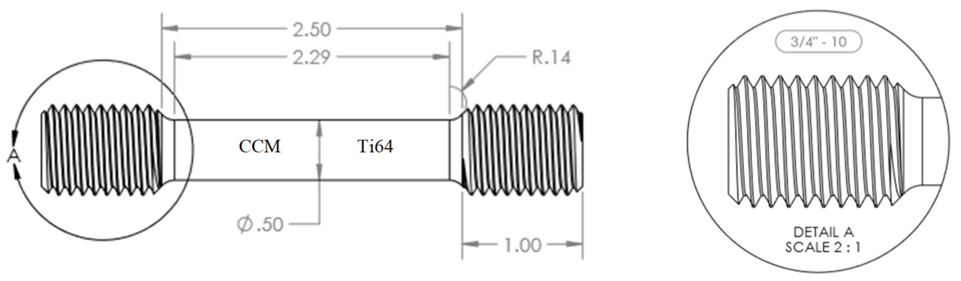
Ti-64 and CCM stock of 10 mm radius were machined into identical workpieces with a gauge length of 58 mm and diameter of 12.7 mm, meeting standard ASTM E8 specifications [
15,
16]. Before placing the workpieces in the welding fixture, the flaying surfaces at the joint interface were lightly polished and cleaned to minimize the presence of potential contaminates during the LFW process.
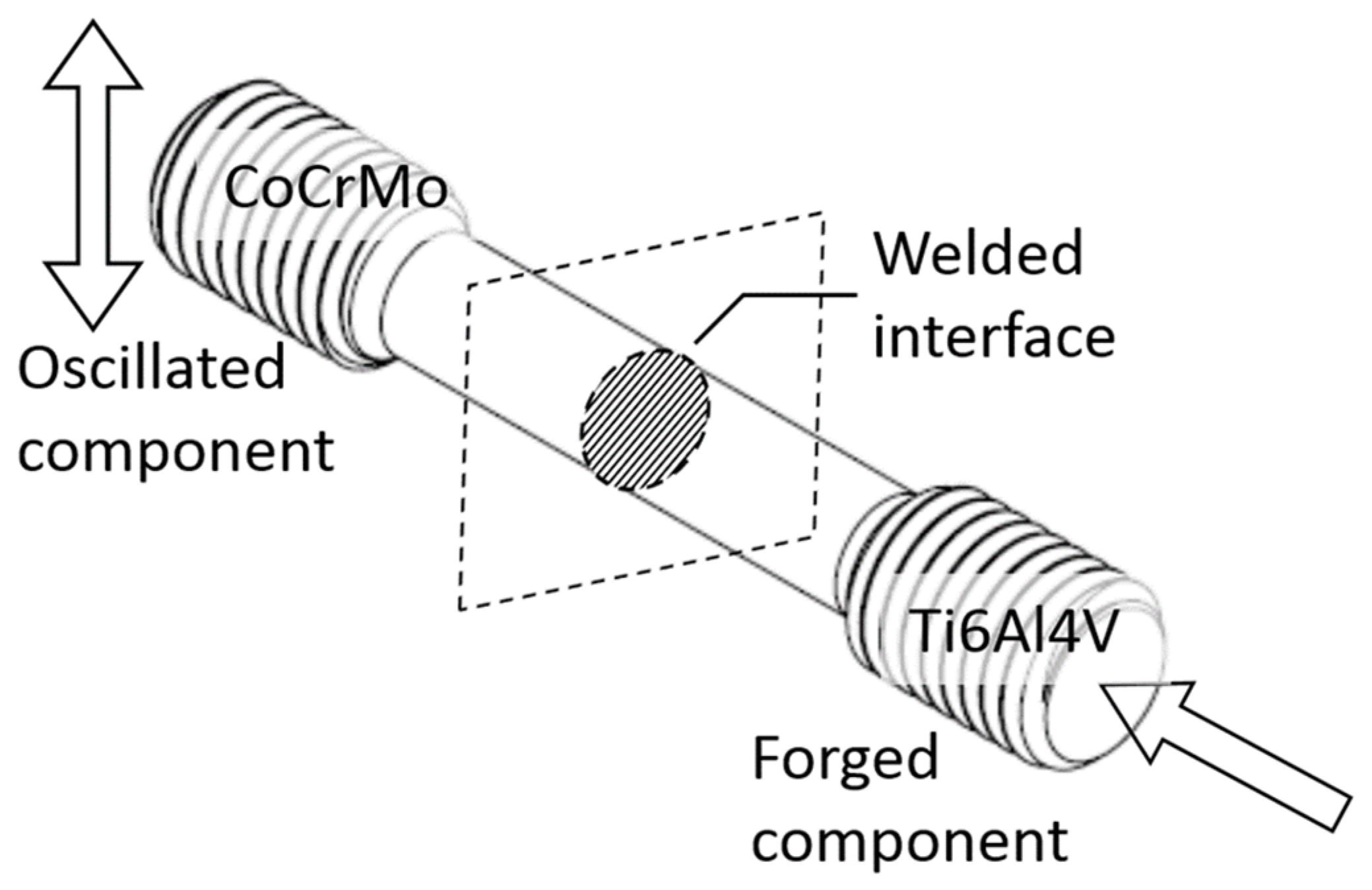
Specimens were orientated such that the CCM specimen was the oscillator while the Ti-64 specimen was restricted to axial movement. An illustration of the LFW process can be seen in
Figure 1, with
Figure 2 showing the dimensions of the workpieces used. The weld tests were divided into two groups based on the forging pressure applied. Additionally, within each group, the burn-off distance was increased with each specimen in the group. This was done to determine the effect that increasing the burn-off distance at different forging pressures has on the resultant bonding strength. The process parameters used for testing the weldability via LFW can be seen in
Table 4.
Temperature history of the welding process was captured via the use of the FLIR A655sc thermal imaging camera. The use of IR camera technology builds upon previous works, in which a high-speed camera was used to visually capture the individual phases of the LFW process for later analysis [
18]. The IR camera was mounted on an extendable tripod and placed in front of the friction welding machine. Before the welding procedure began, the IR camera was calibrated to and focused on the workpieces using FLIR Software following the standard FLIR IR camera calibration procedure (B). As the IR camera is stationary relative to the welding machine, the calibration process was only performed on the first set. The IR camera was considered calibrated for all sets following the first calibration. FLIR Software was also utilized to record, store, and analyze the thermal data. The postprocessing analysis of IR thermal data was performed to determine the time maximum recorded temperature and the time at which it occurred. The welded specimens were rested in ambient for 5 min to ensure the fusion. Afterwards, the flash diameter and axial shortening were measured. Following their measurement, the specimens were prepared for tensile testing. Once the specimens were prepared, tensile testing was conducted in accordance with ASTM E8 standards [
15,
16]. This was done to determine the ultimate tensile strength of the newly welded specimens. The tension was applied at a speed of 4 mm/min corresponding to a strain rate of 0.08 s
−1. To ensure precise strain measurement, a strain gauge was installed at the weld interface.
2.2. Simulation Model
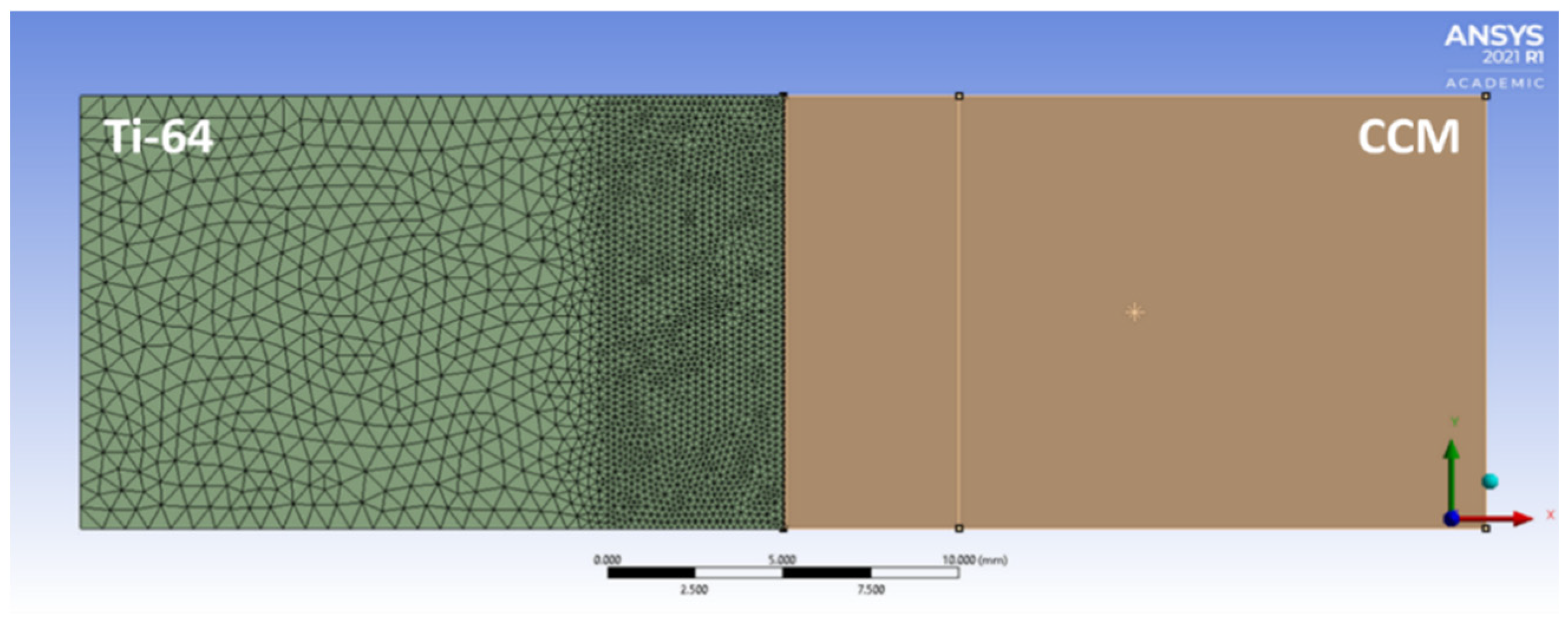
The finite modeling software utilized in this study was ANSYS Workbench 19.1, utilized as the FEA simulation software. A two-dimensional model was implemented, as it can adequately approximate the physics of the problem with reasonable processing times [
19,
20]. The process can be separated into a thermal and a mechanical problem, where the results from the thermal model are applied to the mechanical model [
5,
21]. The geometry size for both models was identical, with the dimensions being 12.7 mm by 40 mm. A fine mesh with an element size of 0.2 mm was used in the thermal model to capture the thermal gradient in detail. To increase the computational efficiency of the model, a triangular mesh was used in the structural model with a fine element size of 0.15 mm along the heat affected zone (HAZ) roughly 5 mm from the weld interface which transitioned into a courser mesh of 1.2 mm for the bulk body. To further increase the computational efficiency, the CCM side was considered rigid as it was the oscillator during the weld process and the bulk of the flash generation was made by the Ti-64. The structural mesh can be seen below in
Figure 3.
2.2.1. Material Properties
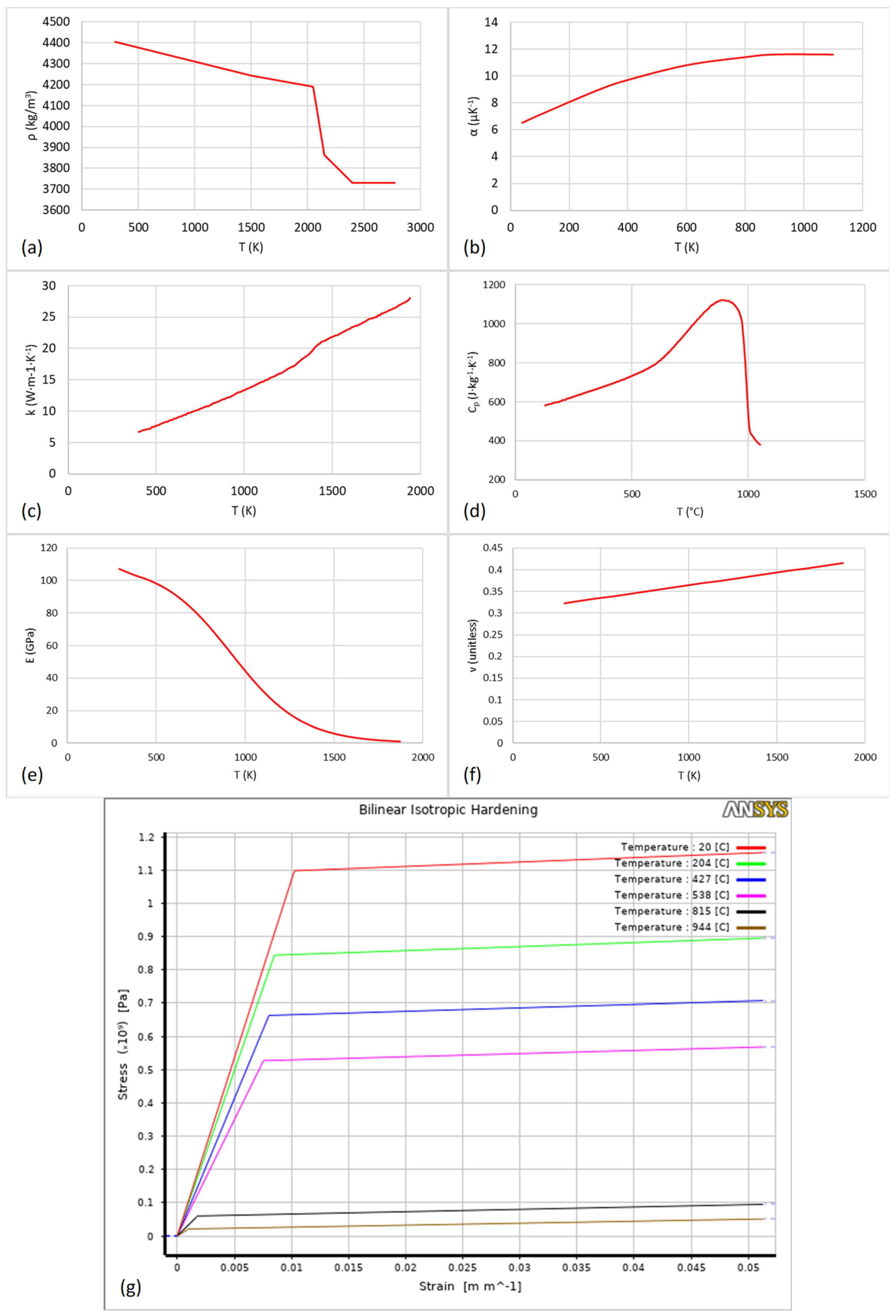
Most material properties are a function of temperature and Ti-64 is no exception. The following plots,
Figure 4a through
Figure 4g, show a graphical summary of the mechanical material properties of Ti-64. The emissivity of Ti-64 was approximated to 0.40. These properties were utilized in both the thermal and structural models.
Cobalt Chrome Molybdenum (CoCrMo) is typically referred to as CCM. Due to CCM’s high wear-resistance, corrosion resistance, and biocompatibility, it is often utilized in the medical industry to produce medical implants [
14]. Typically, it is in the form of artificial joints such as knee and hip joints. It is also utilized in the dental field where it typically serves as the metal framework of partial dentures. Its uses in the non-medical applications are typically limited to areas where high resistance to both corrosion and wear are needed such as wind turbines and engine components. As currently there is virtually no literature detailing the temperature-dependent properties of CCM at elevated temperatures, the material properties of CCM were assumed to be constant. Known thermal and mechanical properties of CCM can be seen below in
Table 5.
2.2.2. Thermal Model
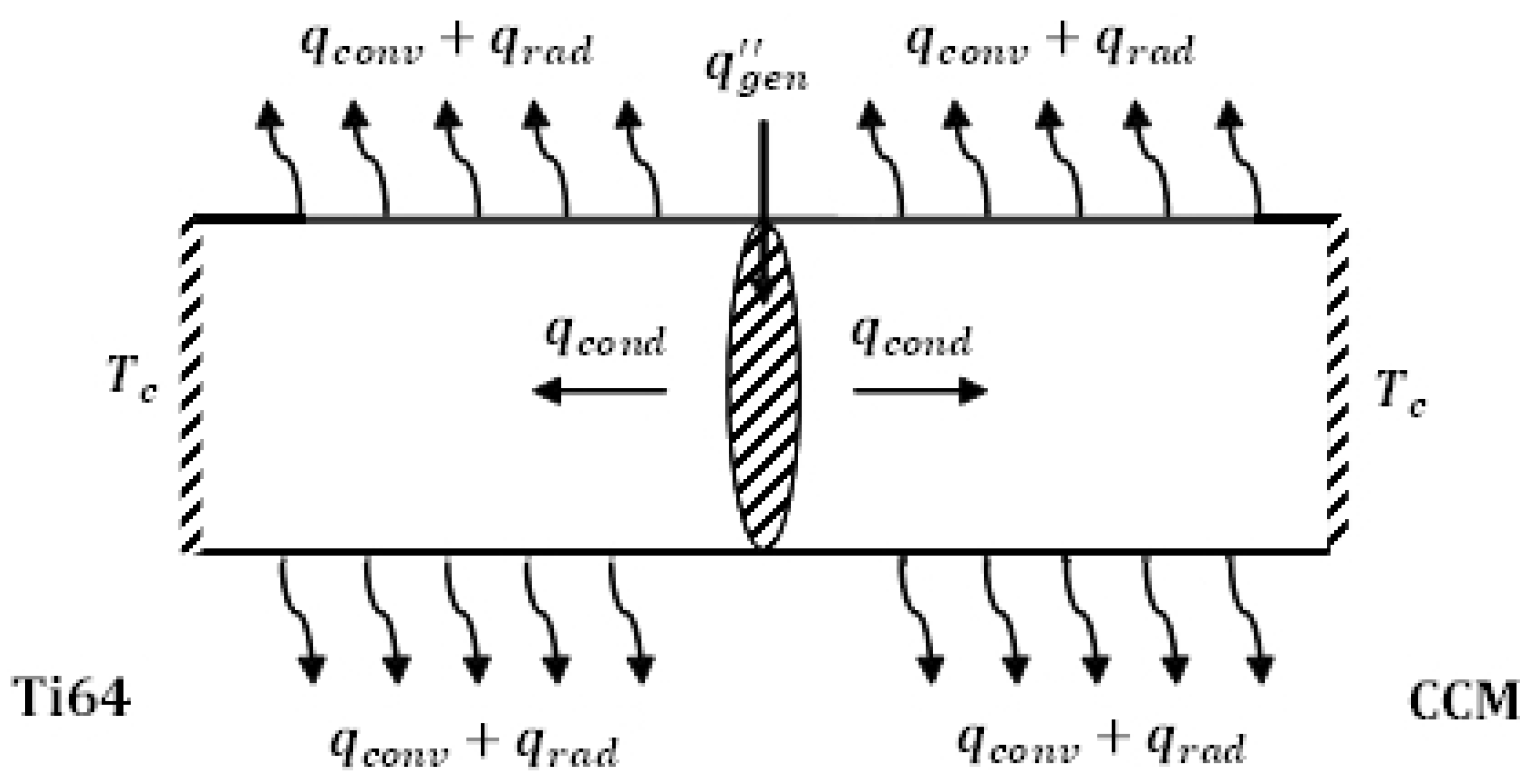
To ensure that the thermal model is accurate and representative of the real-world welding process, the model considers conduction, convection, radiation, and a friction-based heat flux at the weld interface. The ambient temperature was set to 20 °C. As the depth of which the heat flux affects the bulk material temperature is limited, a constant temperature value of 130 °C was applied to the left and rightmost sides of the geometry. The top and bottom edges were subject to heat loss via convection and radiation. The frictional heat flux occurs at the weld interface. An illustration of these thermal boundaries can be found below in
Figure 5.
2.2.3. Structural Model
The compressive loads for the friction and the forging phase were applied as separate loads. The CCM portion was considered rigid and oscillated in the y direction with Ti-64 being fixed in the x direction. The Ti-64 portion was constrained such that the HAZ was allowed to oscillate in the y direction and to compress in the x direction, but the rest of the Ti-64 was only allowed to move the x direction. A compressive load was applied to the Ti-64 section to simulate the axial load that was constantly applied during the weld process. As only the Ti-64 is deforming, only the thermal history of the Ti-64 was imported into the structural model. This allows for the Ti-64 surface to deform around the CCM surface as observed experimentally.
2.2.4. Simulation Model Validation
To ensure the validity and accuracy of the developed model, grid convergence tests were performed on both the thermal and structural portion of the thermomechanical model.
The grid convergence was done by varying the element size and comparing results with those results. The element sizes chosen for the thermal portion were 0.2 mm as the baseline, 0.4 mm for the upper limit, and 0.15 mm for the lower limit. The use of 0.15 mm instead of 0.1 mm was due to software having a limit on the maximum allowable elements for the student version of software. As the error values were well within ±5% for both the thermal and structural grid convergence tests, the model passed was considered stable. The results of the thermal and structural grid convergence tests can be seen in
Table 6 and
Table 7, respectively.
3. Results and Discussion
3.1. Experimental Data
Postprocessing analysis of IR thermal data was performed to determine the time maximum recorded temperature and the time at which it occurred. The IR thermal data was also analyzed to determine the longitudinal thermal profile across the weld interface at all points in time during the welding process.
Figure 6a shows the infrared imaging of the weld joint captured using the FLIR software. The detailed measuring procedure is given in
Appendix B. From that set of thermal profiles at various times, a single thermal profile was chosen to be used as a reference to determine the accuracy of the thermal portion of the coupled thermomechanical simulation model. The thermal profile at which the maximum recorded temperature occurred was chosen to be the reference. This was done to ensure that the maximum temperatures in the thermomechanical model would not exceed the maximum temperatures recorded during the experiment. The plot of the chosen thermal profile can be seen in
Figure 6c.
Both the pressure and axial-shortening during welding were measured by the welding machine during operation. For the purposes of this study, axial shortening was assumed to be identical to burn-off. The pressure and axial shortening for test set 1 can be seen in
Figure 7. It shows a clear delineation between the three stages of the welding process under consideration. Stage 1 is characterized by the generation of zero burn-off. Stage 1 ends at 1.2 s. It is followed by a brief transition of exponential growth ending at 1.5 s. It is followed by stage 2 which is characterized by linear burn-off rates for each sample. Stage 3 is the forging stage, which similar to stage 1 is characterized by zero burn-off. Unlike stage 1, stage 3 has an additional forging pressure load with no oscillation. Unlike the other stages, the starting point of stage 3 varies for each sample as the oscillation amplitude dictates the starting time of stage 3.
After all workpieces were welded, the newly joined workpieces were taken for visual inspection to check for failed welds. From the visual inspection, it was determined that the extruded flash was composed of the plasticized Ti-64. This occurred because Ti-64 undergoes a phase transformation at its β-transus temperature, which occurs around 1000 °C, and therefore softened Ti-64 and produced the flash [
25]. This assertion was verified by examining the CCM phase diagrams which indicate that no such phase transformation occurs within the maximum measured weld temperature. This implies that the majority of extruded plasticization is generated by the Ti-64. The plasticized Ti-64 is then warped around the joint area during the forging phase of the LFW process and quickly solidified. Specimens with extruded radial flash can be seen in
Figure 8.
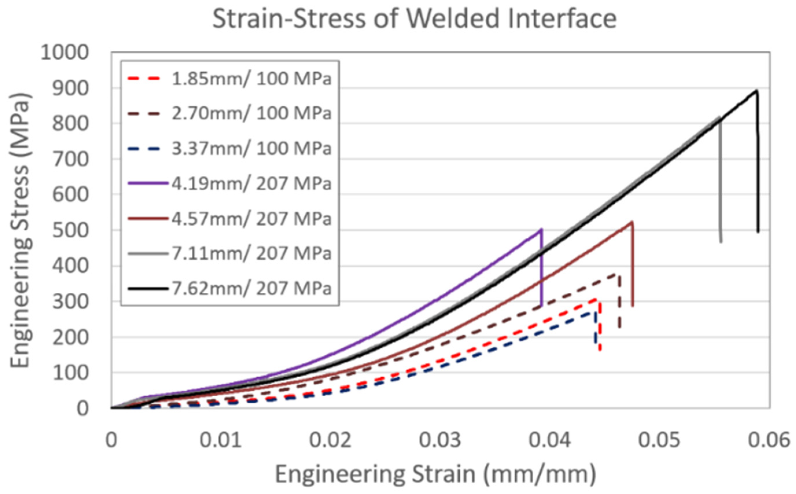
Subsequently, the welded specimens were subject to tensile testing. While none of the specimens had tensile strength exceeding that of the parent materials, specimens 3 and 4 of test set 2 were close to parity with that of Ti-64, with σ
u values of approximately 810 MPa and 895 MPa, both of which are far closer to the Ti-64’s σ
u of 1000 MPa than the other specimens. When comparing specimens 1 and 4, the percent error of specimen 7 is a vast improvement to that of specimen 1 with a 62.5% decrease in error. In addition, the weld strength of specimen 7 is 231.48% greater than that of specimen 1. This indicates that with further parameter optimization, the bonding of Ti-64 to CCM is possible at small amplitudes such as 2 mm, but it requires large forging pressure and a high amount of burn-off.
Figure 9 illustrates the tensile testing results for both test sets.
3.2. Simulation Results
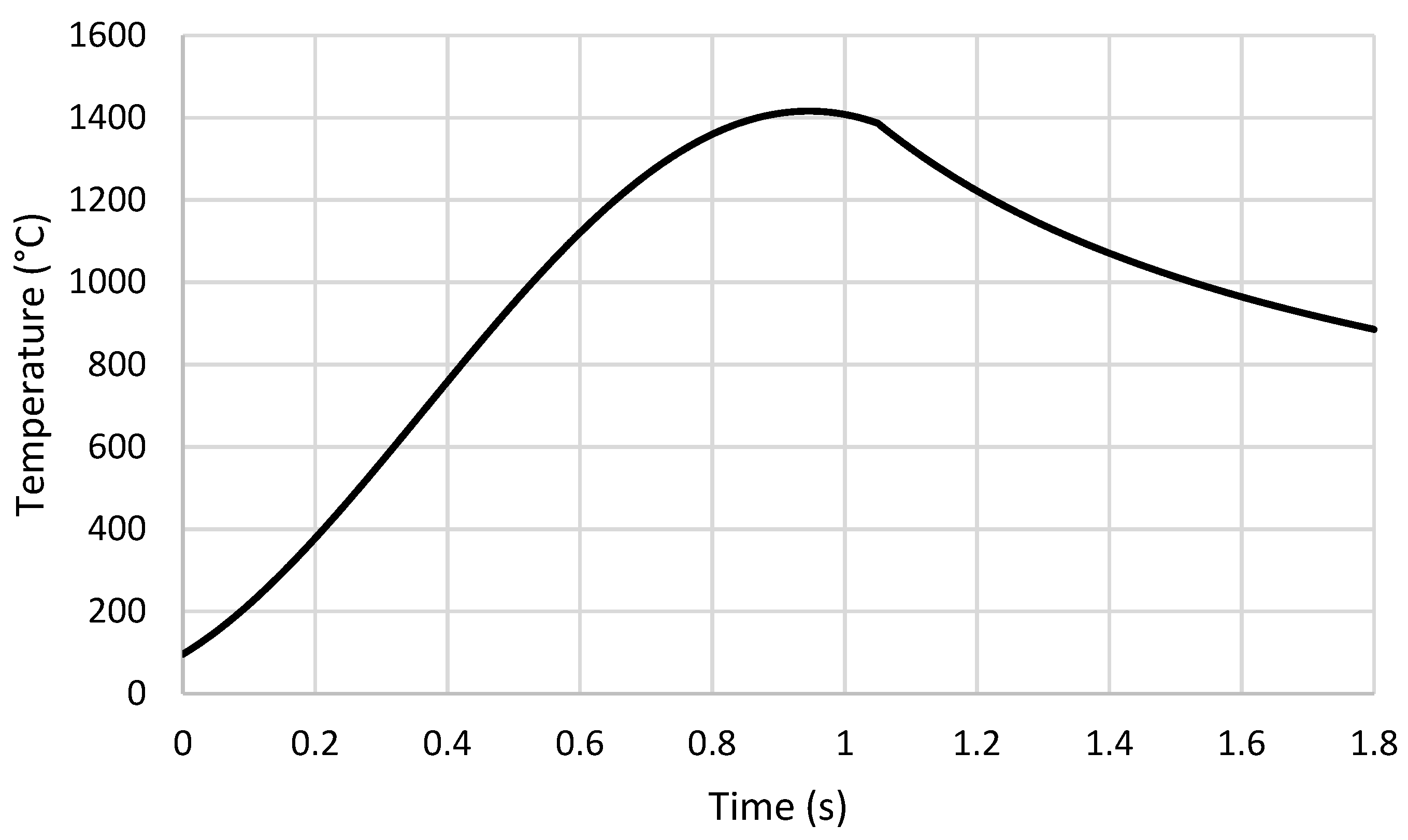
The development of the maximum temperature can be seen in
Figure 10.
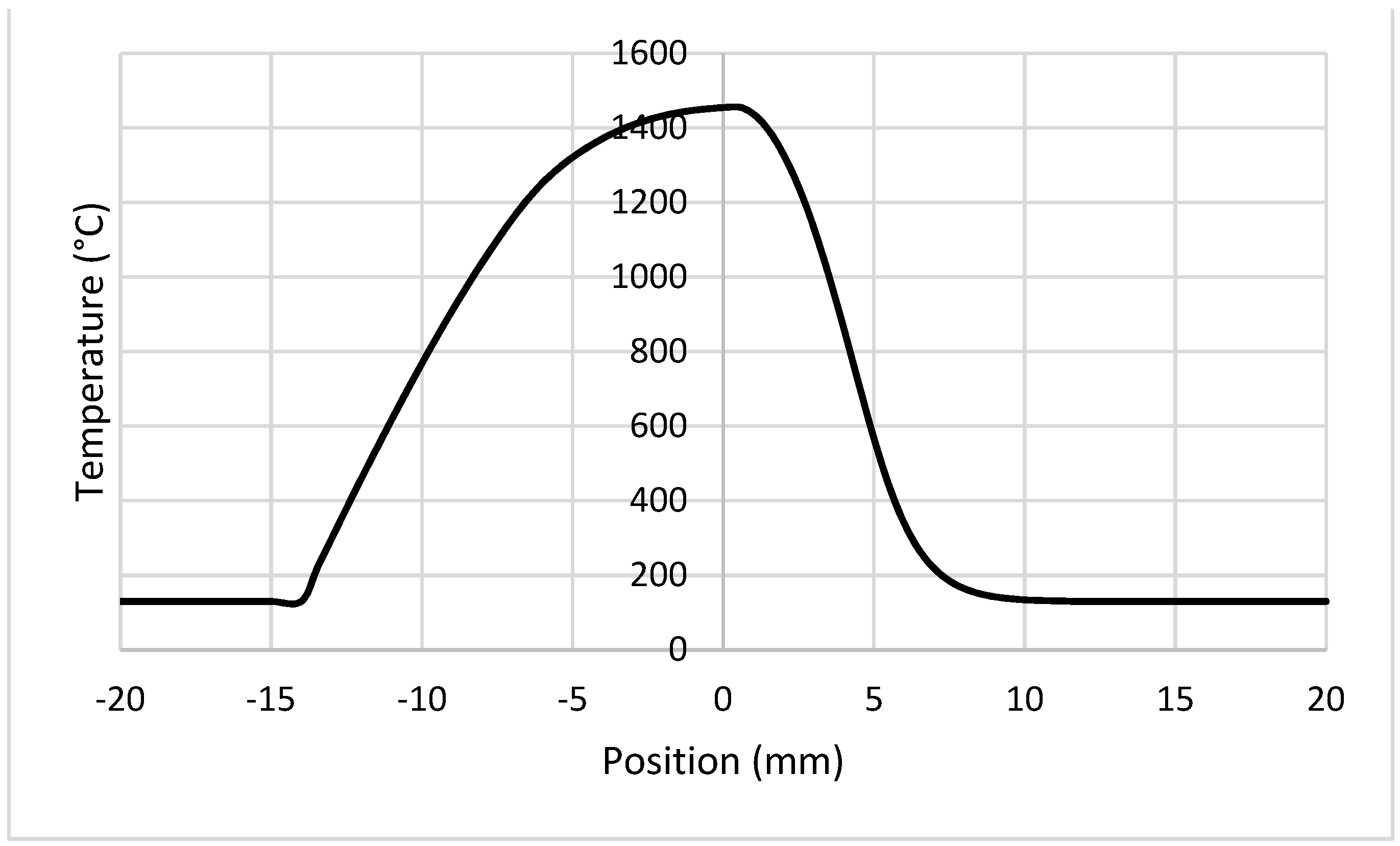
Figure 11 displays the thermal profile across the workpiece at 1.2 s in the simulation.
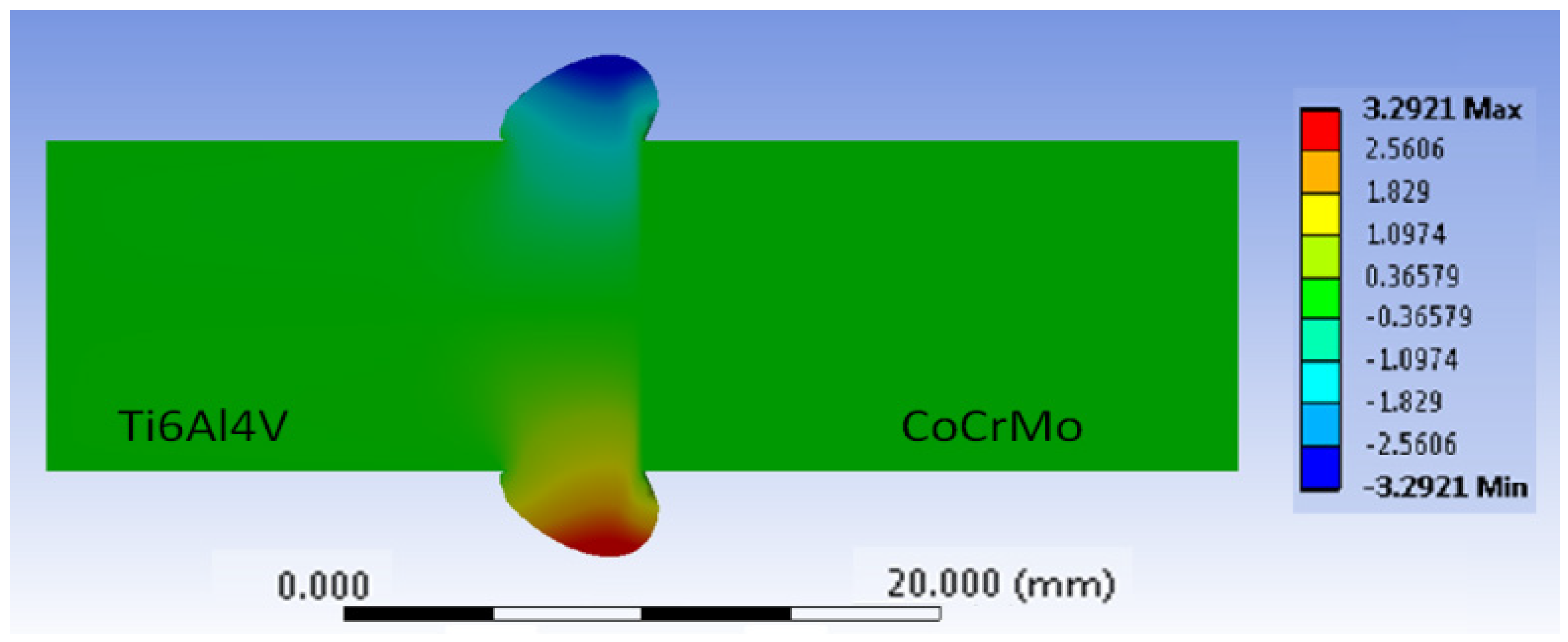
While the structural portion of the simulation model is less computationally efficient than thermal model, it produces results that fall within 5% error compared to experimental results. Therefore, this coupled thermal-structural stress model is suitable as a starting point for generating small-strain thermomechanical modeling. The final deformation field throughout the part can be seen below in
Figure 12.
3.3. Comparative Analysis to Experimental Data
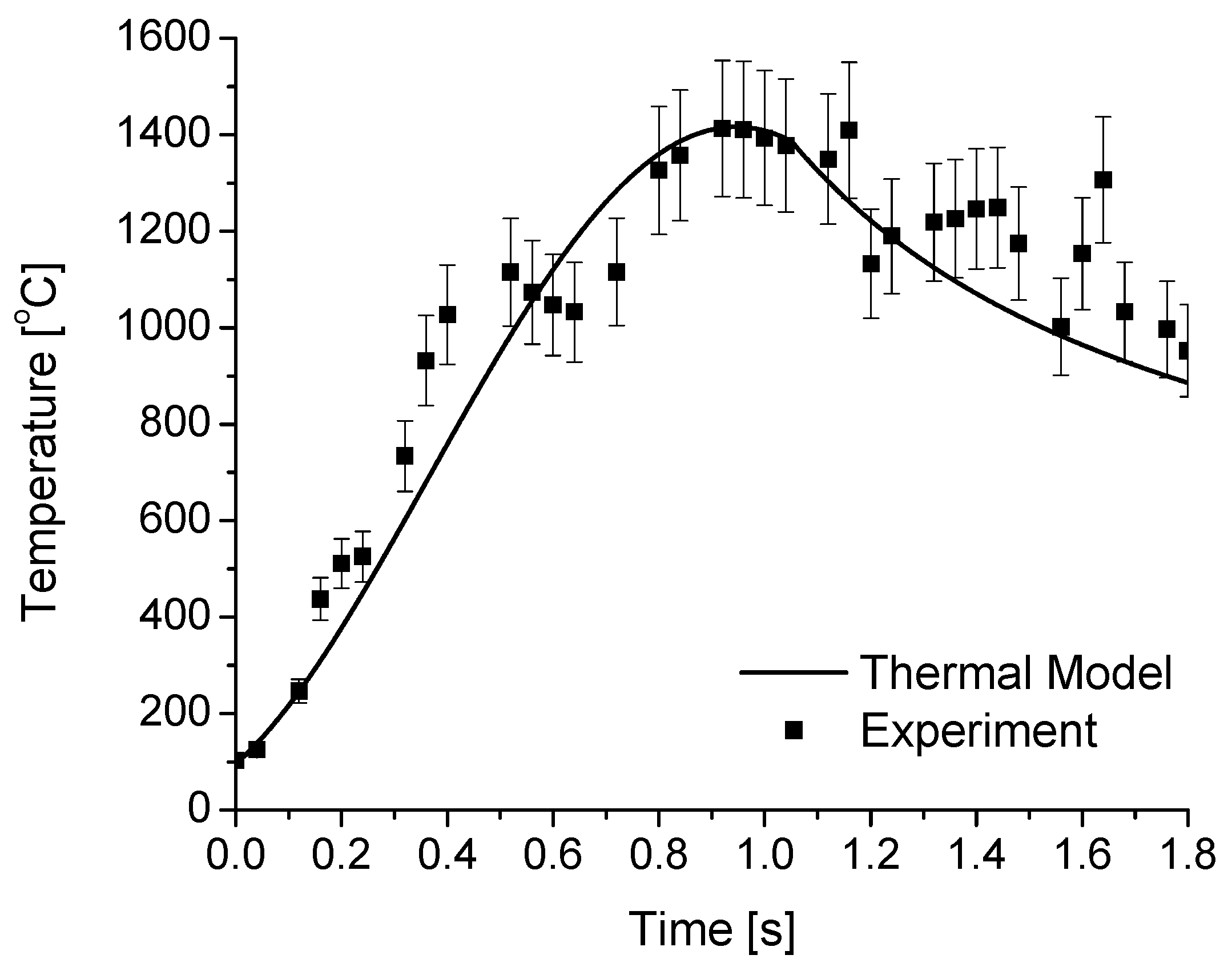
The simulated development of the maximum temperature along the weld interface works well as a trendline of the thermal development data collected during the welding experiment. The comparison between the experimental thermal data and the simulated thermal development can be seen in
Figure 13.
Figure 14 displays the comparison between the thermal data and the simulated cross-sectional thermal profile. Both the simulated thermal development and thermal profile match the thermal data very well. From these figures, it is clear that the thermal model is both laterally and longitudinally accurate. Both figures also show that the profiles fall within 5% of the experimental data. This is of great importance because the thermal model utilizes several approximations to allow for simulation times under 15 min. This also bolsters the assertion that FEA modeling of dissimilar metals undergoes LFW without restrictively long simulation times.
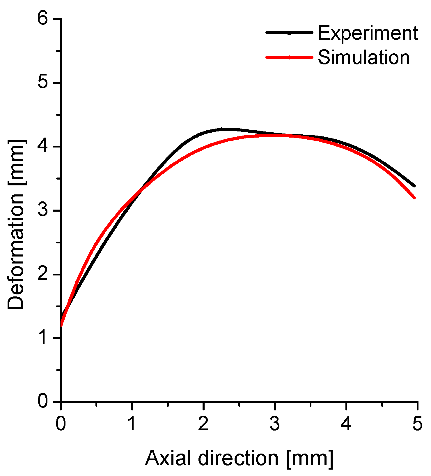
The structural portion of the simulation model, while less computationally efficient, does produce results that fall within 5% error compared to experimental results. Both the simulated and experimental flash profile can be seen below in
Figure 15. Therefore, this coupled thermal-structural stress model is suitable as a starting point for generating small-strain thermomechanical modeling.
4. Conclusions
In the present study, experimental and simulation studies were performed to analyze the weldability of Ti-64 to CCM via LFW. Tensile testing was performed on the test sets to determine if bonding was successful and to compare the weld strength to that of the parent materials. While bonding was successful for all samples, none had weld strengths equal to or exceeding that of their parent materials. Although, specimen 4 was close to parity with the UTS of Ti-64. When comparing specimens 1 and 4, it was found that increased forging pressure greatly improved weld strength, with specimen 4 having a 231.48% increase in weld strength compared to that of test set 1.
A transient simulation analysis was conducted to predict temperature profiles both longitudinal and lateral to the weld interface. The simulation results suggest that: (1) a decoupled 2D thermomechanical model is capable of generating both thermal and deformation results that can match that of experimental data within a 5% error boundary; (2) the structural simulation results indicate that the use of single body/rigid surface is sufficient for producing deformation results within 5% error under a decoupled 2D thermomechanical modeling approach.
The thermal portion of the transient analysis accounted for heat transfer via conduction, convection, and radiation in addition to the heat flux generated by the frictional oscillation. The structural portion accounted for oscillation frequency, amplitude, compressive load, and the forging pressure. The transient analysis did not account for the loss of material via burn-off, instead approximating the material loss to be a part of the material extruded via deformation during the welding process. As both the thermal and structural simulation results fall in line with their respective experimental counterparts, it can be deduced that the exclusion of material loss via burn-off is a valid assumption for this modeling approach.
Author Contributions
Conceptualization, K.C.; methodology, K.C., A.G., J.A.D.-D.l.P. and J.J.R.; software, A.G.; validation, K.C., A.G., J.A.D.-D.l.P. and J.J.R.; formal analysis, K.C., A.G., J.A.D.-D.l.P. and J.J.R.; investigation, K.C., A.G., J.A.D.-D.l.P. and J.J.R.; resources, K.C., A.G., J.A.D.-D.l.P. and J.J.R.; data curation, K.C., A.G., J.A.D.-D.l.P. and J.J.R.; writing—original draft preparation, K.C., A.G., J.A.D.-D.l.P. and J.J.R.; writing—review and editing, K.C., A.G., J.A.D.-D.l.P. and J.J.R.; visualization, K.C., A.G., J.A.D.-D.l.P. and J.J.R.; supervision, K.C.; project administration, K.C.; funding acquisition, K.C. and J.J.R. All authors have read and agreed to the published version of the manuscript.
Funding
This research received no external funding.
Institutional Review Board Statement
Not applicable.
Informed Consent Statement
Not applicable.
Data Availability Statement
Data sharing is not applicable to this article.
Acknowledgments
The authors would like to offer their sincerest gratitude to Frank Deley and Michael Gaskill from Taylor-Winfield (Youngstown, OH), for providing technical support and specimen preparation. The authors also express their sincere gratitude and appreciation to Center for Excellence program (Youngstown State University), for providing financial support.
Conflicts of Interest
The authors declare no conflict of interest.
Appendix A
Table A1.
Mechanical properties of metallic implant materials [
9,
24].
Table A1.
Mechanical properties of metallic implant materials [
9,
24].
| Materials | σy (MPa) | σu (MPa) | E (GPa) |
|---|
| Ti6Al4V (F136) | 924 | 1000 | 116 |
| CoCrMo (F1537) | 958 | 1338 | 210 |
| TiMo-β (F2066) | 483 | 690 | 78 |
| Ti45Nb | 480 | 546 | 62 |
| Human cortical bone | - | - | 25.8 |
Appendix B
IR Camera Calibration Procedure
Assemble camera and power it on.
Open FLIR IR camera software on laptop.
Activate IR camera from with software.
Set frame rate to 20 fps set thermal range to -10 to 150 Celsius.
Open camera calibration settings with software.
Place an object of known temperature on or near object of interest, then select autofocus in the software.
If the object of interest is still out of focus manually adjust the focus of camera with the settings panel.
Once object of interest is focused on, set thermal range to desired range for the experiment.
Go to camera settings and set camera capture method to start/stop.
References
- Bertrand, S. Finite Element Modeling of the Linear Friction Welding Process. Ph.D. Thesis, Université du Québec, Montreal, QC, Canada, 2019. [Google Scholar]
- Flipo, B.; Beamish, K.; Humphreys, B.; Wood, M.; Shilton, A. Linear Friction Welding of TI 6AL 4V for Aerostructure Applications. In Trends in Welding Research, Proceedings of the 10th International Conference, Tokyo, Japan, 11–14 October 2016; TWI: Cambridge, UK, 2016. [Google Scholar]
- McAndrew, A.R.; Colegrove, P.; Bühr, C.; Flipo, B.C.; Vairis, A. A literature review of Ti-6Al-4V linear friction welding. Prog. Mater. Sci. 2018, 92, 225–257. [Google Scholar] [CrossRef]
- Chamanfar, A.; Jahazi, M.; Cormier, J. A Review on Inertia and Linear Friction Welding of Ni-Based Superalloys. Met. Mater. Trans. A 2015, 46, 1639–1669. [Google Scholar] [CrossRef]
- Jedrasiak, P.; Shercliff, H.; McAndrew, A.; Colegrove, P. Thermal modelling of linear friction welding. Mater. Des. 2018, 156, 362–369. [Google Scholar] [CrossRef]
- Lee, L.A.; McAndrew, A.; Buhr, C.; Beamish, K.A.; Colegrove, P.A. 2D Linear Friction Weld Modelling of a Ti-6Al-4V T-Joint. J. Eng. Sci. Technol. Rev. 2015, 8, 44–48. [Google Scholar] [CrossRef]
- McAndrew, A.R. Modelling of Ti-6Al-4V Linear Friction Welds. Ph.D. Thesis, Cranfield University, Bedfordshire, UK, 2015. [Google Scholar]
- Avval, P.T.; Samiezadeh, S.; Klika, V.; Bougherara, H. Investigating stress shielding spanned by biomimetic polymer-composite vs. metallic hip stem: A computational study using mechano-biochemical model. J. Mech. Behav. Biomed. Mater. 2015, 41, 56–67. [Google Scholar] [CrossRef] [PubMed]
- Rho, J.-Y.; Tsui, T.Y.; Pharr, G.M. Elastic properties of human cortical and trabecular lamellar bone measured by nanoindentation. Biomaterials 1998, 18, 1325–1330. [Google Scholar] [CrossRef]
- Oladokun, A.; Pettersson, M.; Bryant, M.; Engqvist, H.; Persson, C.; Hall, R.; Neville, A. Fretting of CoCrMo and Ti6Al4V alloys in modular prostheses. Tribol.-Mater. Surf. Interfaces 2015, 9, 165–173. [Google Scholar] [CrossRef] [Green Version]
- McAndrew, A.R.; Flipo, B.C.D. Linear Friction Welding for Near Net Shape Manufacturing of Titanium Alloy Ti-6Al-4V Aerospace Components. In Proceedings of the 2018 9th International Conference on Mechanical and Aerospace Engineering (ICMAE), Budapest, Hungary, 10–11 July 2018. [Google Scholar] [CrossRef]
- Semlitsch, M. Titanium alloys for hip joint replacements. Clin. Mater. 1987, 2, 1–13. [Google Scholar] [CrossRef]
- Kunčická, L.; Kocich, R.; Lowe, T.C. Advances in metals and alloys for joint replacement. Prog. Mater. Sci. 2017, 88, 232–280. [Google Scholar] [CrossRef]
- Moghadasi, K.; Isa, M.S.M.; Ariffin, M.A.; Jamil, M.Z.M.; Raja, S.; Wu, B.; Yamani, M.; Bin Muhamad, M.R.; Yusof, F.; Jamaludin, M.F.; et al. A review on biomedical implant materials and the effect of friction stir based techniques on their mechanical and tribological properties. J. Mater. Res. Technol. 2022, 17, 1054–1121. [Google Scholar] [CrossRef]
- ASTM Standard. Standard Test Methods for Tension Testing of Metallic Materials; ASTM International: West Conshohocken, PA, USA, 2013. [Google Scholar]
- ASTM Standard. Standard Specification for Wrought Cobalt-28Chromium-6Molybdenum Alloys for Surgical Implants; ASTM International: West Conshohocken, PA, USA, 2011. [Google Scholar]
- Irwin, D.; Seydlorsky, C.; Gautam, A.; Glaspell, A.W.; Choo, K.; Ryu, J. Dissimilar linear friction welding technology for manufacturing of functional materials: Bi-metallic Ti6Al4V-CoCrMo joint implants. In Proceedings of the Summer Biomechanics, Bioengineering, and Biotransport Conference, Seven Springs, PA, USA, 25–28 June 2019. [Google Scholar]
- Geng, P.; Qin, G.; Li, C.; Wang, H.; Zhou, J. Study on the importance of thermo-elastic effects in FE simulations of linear friction welding. J. Manuf. Process. 2020, 56, 602–615. [Google Scholar] [CrossRef]
- McAndrew, A.R.; Colegrove, P.A.; Addison, A.C.; Flipo, B.C.; Russel, M.J.; Lee, L.A. Modelling of the workpiece geometry effects on Ti–6Al–4V linear friction welds. Mater. Des. 2015, 87, 1087–1099. [Google Scholar] [CrossRef] [Green Version]
- Turner, R.; Ward, R.M.; March, R.; Reed, R.C. The Magnitude and Origin of Residual Stress in Ti-6Al-4V Linear Friction Welds: An Investigation by Validated Numerical Modeling. Met. Mater. Trans. A 2012, 43, 186–197. [Google Scholar] [CrossRef]
- Jedrasiak, P.; Shercliff, H. Modelling of heat generation in linear friction welding using a small strain finite element method. Mater. Des. 2019, 177, 107833. [Google Scholar] [CrossRef]
- ANSYS. Ti-6AL-4V Material Properties; ANSYS, Inc.: Canonsburg, PA, USA, 2021. [Google Scholar]
- Boivineau, M.; Cagran, C.; Doytier, D.; Eyraud, V.; Nadal, M.-H.; Wilthan, B.; Pottlacher, G. Thermophysical Properties of Solid and Liquid Ti-6Al-4V (TA6V) Alloy. Int. J. Thermophys. 2006, 27, 507–529. [Google Scholar] [CrossRef]
- Glaspell, A.; Seydlorsky, C.; Son, J.; Ryu, J.J.; Choo, K. Thermal Stress Simulation Model of Dissimilar Linear Friction Welding (LFW) Technology for Manufacturing of Bi-Metallic Biomedical Implants. In Proceedings of the ASME International Manufacturing Science and Engineering Conference, Online, 3 September 2020. [Google Scholar] [CrossRef]
- Lu, X.; Lin, X.; Chiumenti, M.; Cervera, M.; Li, J.; Ma, L.; Wei, L.; Hu, Y.; Huang, W. Finite element analysis and experimental validation of the thermomechanical behavior in laser solid forming of Ti-6Al-4V. Addit. Manuf. 2018, 21, 30–40. [Google Scholar] [CrossRef]
| Publisher’s Note: MDPI stays neutral with regard to jurisdictional claims in published maps and institutional affiliations. |
© 2022 by the authors. Licensee MDPI, Basel, Switzerland. This article is an open access article distributed under the terms and conditions of the Creative Commons Attribution (CC BY) license (https://creativecommons.org/licenses/by/4.0/).


