Article

Optimal Scheduling of Reconfigurable Microgrids in Both Grid-Connected and Isolated Modes Considering the Uncertainty of DERs

1
Department of Electrical Engineering, University of Zanjan, Zanjan 45371-38791, Iran
2
School of Engineering, Newcastle University, Newcastle, Upon Tyne NE1 7RU, UK
3
School of Electrical and Electronic Engineering, University College Dublin, D04 V1W8 Dublin, Ireland
*
Author to whom correspondence should be addressed.
Energies 2022, 15(15), 5369; https://doi.org/10.3390/en15155369
Submission received: 20 June 2022 / Revised: 8 July 2022 / Accepted: 21 July 2022 / Published: 25 July 2022
(This article belongs to the Special Issue Distributed Generation Power Systems)

Abstract

:
In this study, an operation strategy is introduced for distributed energy resources (DERs) in reconfigurable microgrids (MGs) to improve voltage profiles, minimize power losses, and boost the system performance. The proposed methodology aims to minimize power loss and energy not supplied (ENS) in MGs with an intelligent share of DERs and network reconfiguration in grid-connected and islanded modes. Due to the inherent uncertain nature of renewable DERs, these sources’ power output is considered as an uncertain parameter, and its effect on the system characteristics is analyzed. The state-of-the-art information gap decision theory (IGDT) approach is utilized to explore different decision-making strategies in the energy scheduling of reconfigurable MGs to deal with such uncertainty. To validate the effectiveness of the proposed method, the IEEE 33-bus radial system is utilized as the test MG. The simulation results show the importance of energy storage systems and reconfiguration in dealing with uncertainty and improving system reliability.

1. Introduction

A microgrid (MG) is represented by a group of interconnected loads and distributed energy resources (DERs) within defined electrical boundaries, which act as a single controllable entity that can operate in both grid-connected and disconnect modes (known as “islanding”) [1]. Different control strategies should be designed for each operating mode; therefore, a high-velocity off-grid algorithm must adjust the control strategy. In an on-grid state, the MG is electrically connected to the upstream electricity network, and according to the load capacity and grid conditions, power is exchanged with the main grid. In the grid-connected mode, the voltage and frequency of the MG are governed by a central controller, while the distributed generations (DGs) within the MG inject predetermined capacities. On the other hand, an islanding state may occur due to either intentional or unintentional contingencies or in cases with lower access to the main grid. Under such circumstances, regulating the voltage, frequency, and supply of MG loads is the responsibility of internal DSRs. MGs are essentially an active distribution network, thanks to composed DERs with different capacities in the distribution of voltage levels [2]. They can contribute to loss reduction and manage blackouts by shortening the gap between production and consumption and significantly facilitating the maintenance process [3].
As stated, DERs play a crucial role in the supply of power systems, with considerable operational and technical advantages for MGs, especially those in rural areas with lower access to the main network. Meanwhile, the efficient performance of such units is more likely to be affected by their location and capacity in the grid [4]. Consequently, various goals, reducing power losses, and improving voltage stability and reliability, for instance, could be followed by installing DERs [5]. Among the DERs, the utilization of renewable DG units is proliferating worldwide due to the environmental and economic advantages that they provide for the system. Renewable energy has become attractive due to its great potential in cutting down greenhouse gas emissions. In many countries, electricity consumers are encouraged to harness renewable energy. Renewable energy sources in microgrids have been actively used in several applications including residential [6], industries [7], university districts [8], and logistics facilities [9].
Optimal DG allocation provides the best DG location and size for optimizing MG scheduling considering DG capacity constraints. This allocation scheme is an effective measure to decrease an MG’s power and energy loss and improve its reliability [10]. However, such green energy resources suffer from a dramatic drawback, which is the fluctuation of their output. Known as uncertainty, such variability in the generated power brings about several challenges for the system operators. Under such circumstances, other kinds of DERs, such as energy storage systems (ESSs), can augment the penetration of renewable DG in the MGs.
A wide variety of research has been conducted to analyze several aspects of the optimal scheduling of MGs under the influence of different technologies and methods. Reference [11] addressed an integrated energy management strategy for next generation green ports. The problem defined by the authors aims at minimizing the total lateness cost of operation and total energy costs considering hourly energy price while taking into account the uncertainty of renewable power generation. In [12], a new MOEA/D based approach is presented to optimally design a PV/Wind/Diesel Hybrid Microgrid considering load uncertainty for a real case study in the city of Yanbu, Saudi Arabia. The authors in [13] presented a new approach for the optimal allocation of DG and ESSs in MGs. A dynamic capacity adjustment algorithm is incorporated in a matrix real-coded genetic algorithm framework to deal with the non-smooth cost functions. With the increasing integration of DERs in the power grid, a decentralized approach becomes essential for scheduling and allocating resources in a smart grid. Reference [14] presented a systematic review of the application of multi-agent systems for economic dispatch and unit commitment in a smart grid. The integration of DERs into a grid requires a decentralized control strategy to incorporate these resources and maintain grid resiliency. The multi-agent technology is a promising and scalable platform to implement distributed resource scheduling and allocation using various computational techniques. In [15], a general exploration of MGs has been provided, including economic analysis as a key factor in evaluating the system’s performance. The authors in [16,17] presented a fault detection, localization, and categorization method for DC MGs which are supplied by PVs.
Despite the significant advantages of renewable energy sources (RESs), their uncertain output is a stumbling block against their high penetration in power systems. To deal with the uncertainty of renewable power generation, in [18], a two-stage stochastic programming approach is presented for optimal scheduling of resilient MGs, considering various uncertainties such as wind energy, electric vehicle availability, and market price. Kumar et al. [19] investigated the uncertainty in RESs’ power availability and load estimation in an MG environment, potentially extending the work to other areas such as customer preferences, demand-side management, reliability, etc. However, the methods that have been utilized for handling the uncertainty require a lot of information about the uncertain parameters and upset the computation time. One of the effective methodologies for decision-making under uncertainty is information gap decision theory (IGDT) [20]. The IGDT is a decision-making method that has been utilized in various power system applications such as generation asset allocation [21], day-ahead scheduling of electric vehicle aggregators [22], transmission planning [23], bidding strategy [24], restoration of distribution networks [25], and distribution network congestion management [26].
Along with the installation of DERs in the MGs, the possibility of changing the status of system switches, known as system reconfiguration, is regarded as another potential modernization of small-scale grids [27]. Network reconfiguration is defined as the process of making changes in the network topology using tie-switches and sectionalizers, known as ‘normally open’ and ‘normally close’ switches, respectively [28,29]. Network reconfiguration is a hybrid non-linear problem that is limited according to the operational limitations of the power system. The goal of utilizing network reconfiguration is to improve characteristics of the system, such as power loss reduction, by identifying the best switch combination in an optimal manner.
The methods in network reconfiguration models can be divided into three groups: innovative methods, mathematical methods, and meta-heuristic methods. These methods differ in finding the best answer, convergence speed, accuracy, and precision [30]. In [31], a method of accurate revision of the minimum grid losses based on mixed integer convex programming is presented. In [32], a harmonic search algorithm is proposed, while in [33], the effect of optimal scatter distribution replacement on active power losses has been extended. In [34], a new load restoration method is proposed to facilitate resilient grids after natural disasters. The MG formulation and reconfiguration are considered and coordinated by sectionalizing the switches so that operational flexibility can be better exploited to enhance electricity supply continuity.
Due to the significance of network reconfiguration in improving system performance, it could be utilized in MGs optimally and efficiently, using sectionalizing and tie-switches. In [35], different MG reconfiguration methods have been explored, categorizing them based on the objective functions, constraints, optimization techniques, and uncertainty handling techniques. The authors in [34] developed a new analytical model to estimate real-time variations in frequency and voltage in an MG resulting from network reconfiguration.
The taxonomy of previous literature on MG scheduling is given in Table 1. To the best of the authors’ knowledge, several methods have been proposed for the optimal allocation of DG and network reconfiguration in distribution grids to minimize losses. However, little research has been conducted to reconfigure the MG both in grid-connected and isolated modes to reduce losses and improve reliability. Accordingly, in this study, a comprehensive mathematical method is introduced to reconfigure MGs in both islanded and grid-connected modes. The uncertainty of DERs is taken into account using the well-known IGDT technique. The model follows multiple goals, making a trade-off between active power loss reduction and energy not supplied and using the weighted sum technique. The introduced model is mixed integer non-linear programming (MINLP), tested on an IEEE 33-bus as the MG test system. Generally, the main highlighting features of this study are:
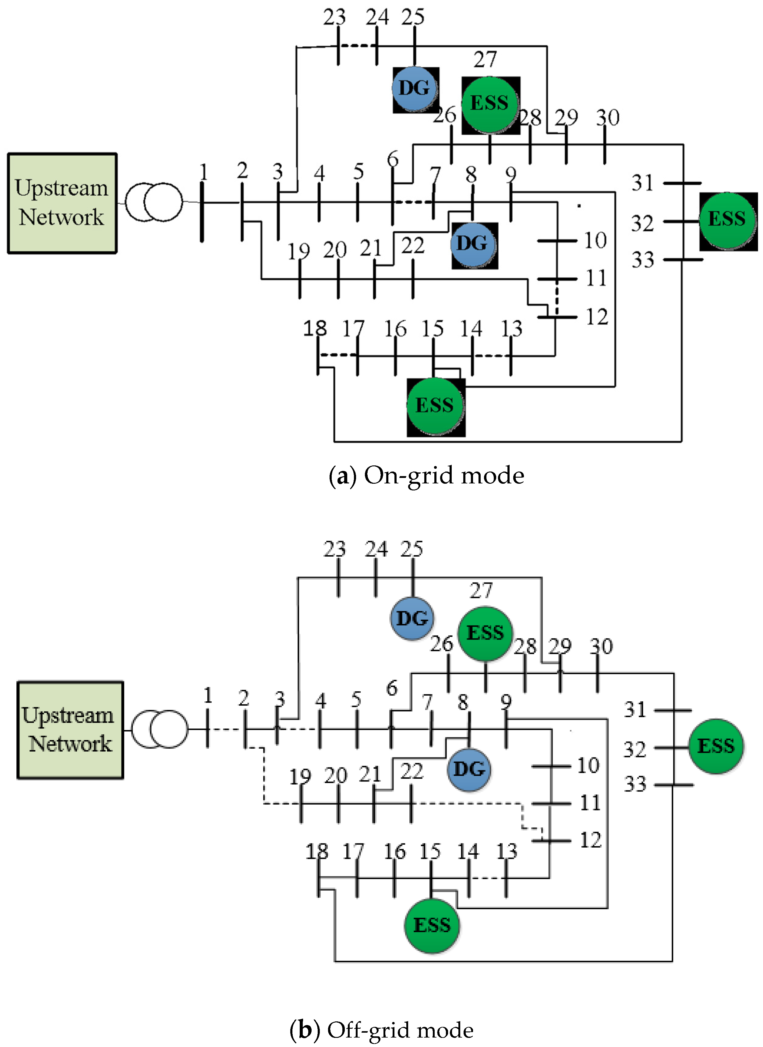
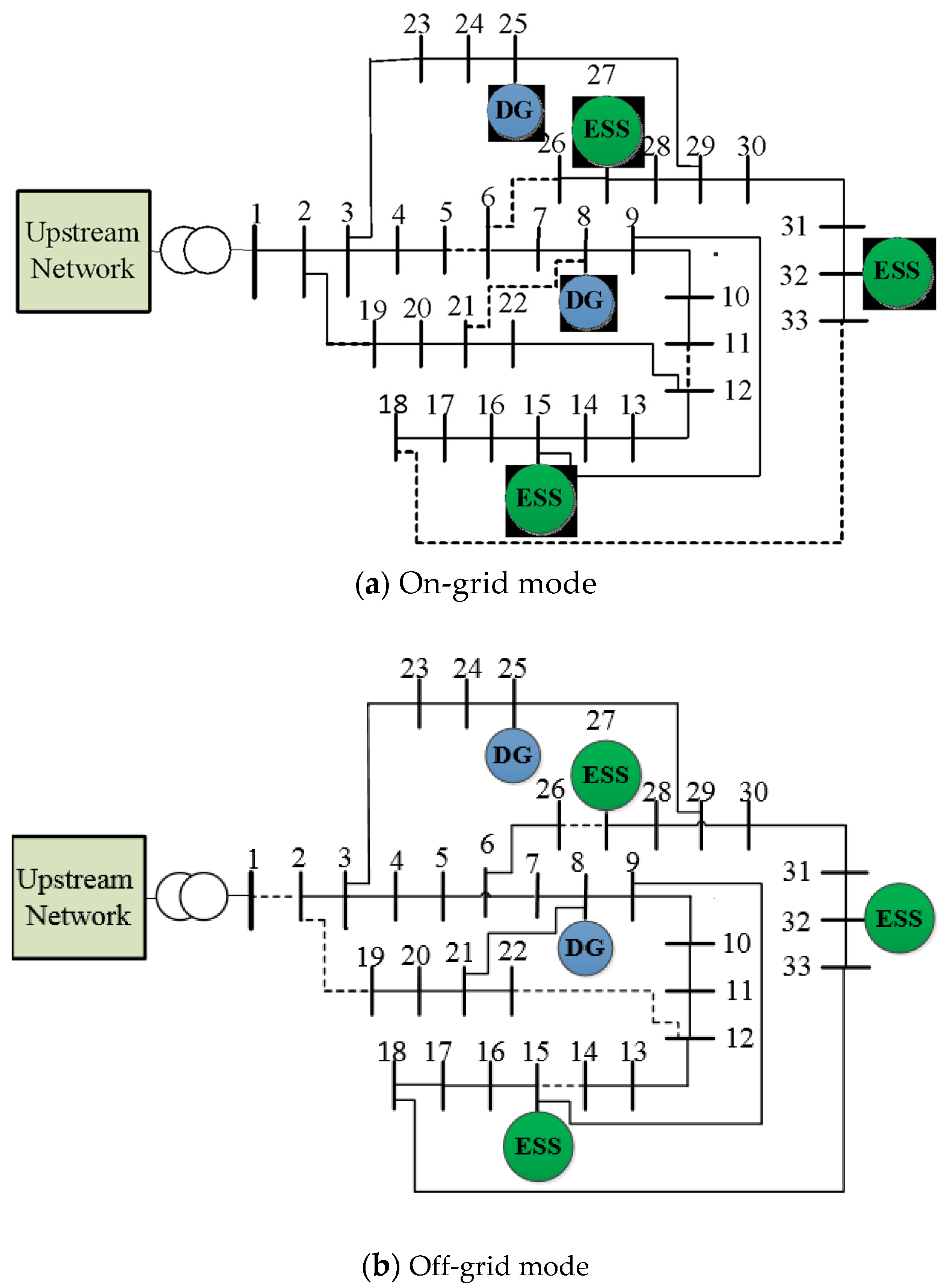
  • Proposing a comprehensive mathematical model for reconfiguration of MGs in both grid-connected and islanded modes.
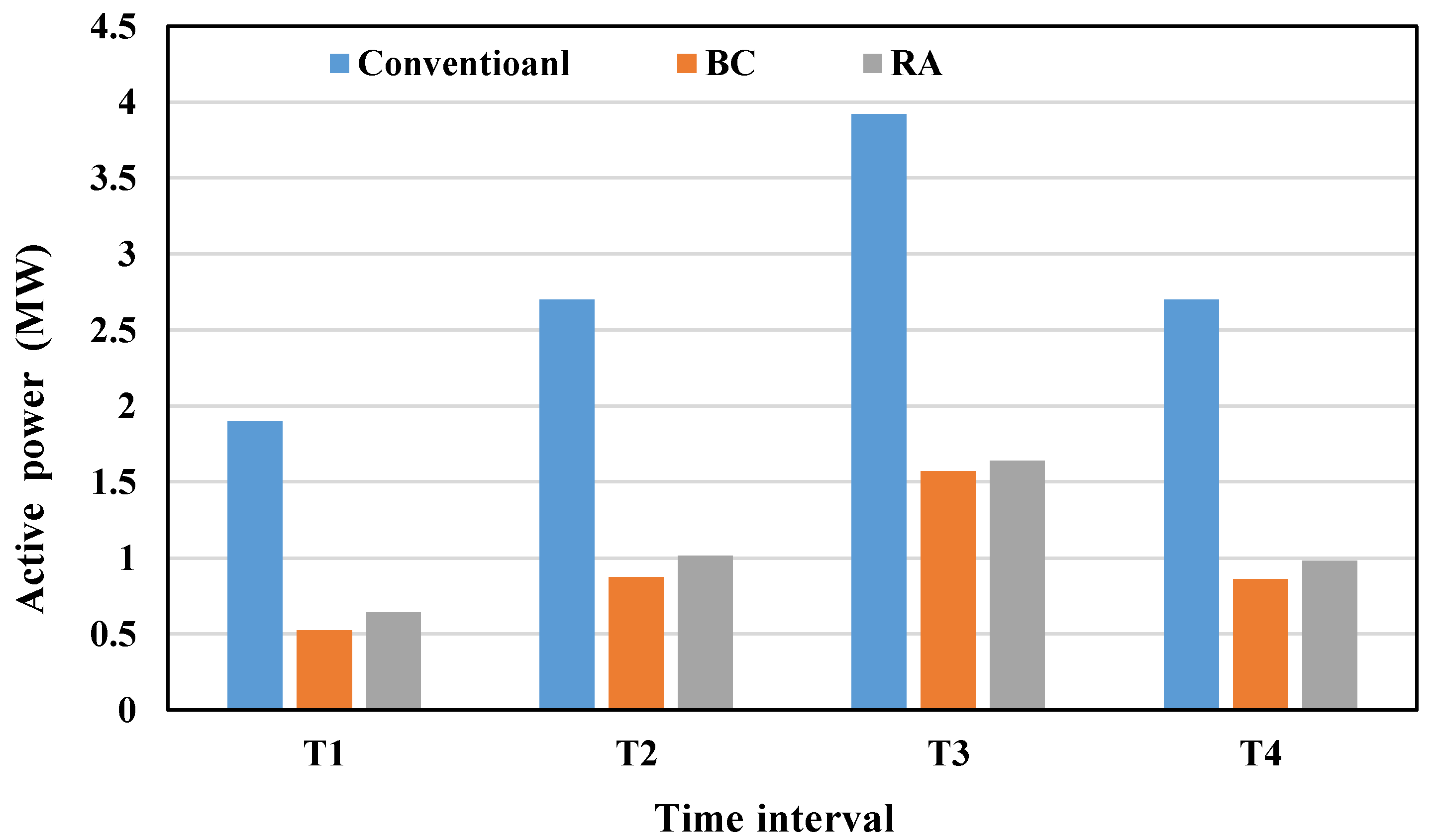
  • Analyzing the active power losses and energy not supplied simultaneously in MG scheduling, in both grid-connected and isolated operation modes.
The remainder of this paper is organized as follows. Section 2 presents the uncertainty modeling technique. Problem formulation is presented in Section 3. Section 4 analyzes the simulation results. Finally, the main conclusion of the paper is given in Section 5.

2. Uncertainty Modeling

Various models have been created to deal with existing uncertainties. Various approaches have been used in distribution grid studies to model uncertainty from a wide range of methods, including probabilistic, possibilistic, hybrid (probabilistic–possibilistic), IGDT, and robust optimization [37]. The main difference between these methods is the use of different solutions to define the uncertainty of input parameters. For example, the probabilistic distribution function is used in stochastic approaches, while a membership is adopted in the fuzzy method to model the uncertainty of input parameters. This study uses the IGDT technique to investigate the influence of the uncertainty on the research hypothesis followed by the model. The IGDT method is a decision-making method that aims to maximize system robustness in the face of severe uncertainties.

Principles of Information Gap Decision Theory

IGDT is an efficient method of describing uncertainty [37], as it does not require much information about the uncertain parameter, enabling it to be utilized to model the uncertainty of different phenomena with unknown practical knowledge about their behavior. Moreover, this method benefits from considerably lower computational time than other techniques such as stochastic optimization [38]. This method seeks to determine the maximum allowable radius of uncertainty for uncertainty entities such as parameters, vectors, or functions. The answer obtained from the IGDT method is accurate and efficient. In the following, this method is briefly explained.
As an optimization problem, this method contains objective function, equality, and inequality constraints, as follows:
o f = m i n x ( f ( X , γ ) )
G j ( X , γ ) = 0
H i ( X , γ ) 0
γ Γ
where Γ describes the set of uncertain parameters and X is the set of decision variables. The objective function shown in Equation (1) is optimized based on both the decision variable X and the uncertainty parameter γ . Equations (2) and (3) represent the equality and inequality constraints, respectively. The mathematical description of uncertainty is as follows:
Γ = Γ ( γ _ , α ) = { γ : | γ γ _ γ _ | α }
where γ _ is the predicted value of the uncertain parameter; α is the maximum possible deviation of the predicted uncertainty parameter from its predicted value, which is referred as the radius of uncertainty.
In order to evaluate the effect of uncertainty using the IGDT method, there is a need to obtain the solution in a base case (BC), according to the predicted value of input parameters. Then, the second level of optimization can follow various decision-making strategies. The BC optimization problem is described by (1)–(4) and assumes that the uncertain parameter has no deviation from its predicted value.
o f b = m i n x ( f ( X , γ _ ) )
G j ( X , γ _ ) = 0
H i ( X , γ _ ) 0  
Based on the output obtained from Equations (6)–(8), the BC value of the objective function is obtained. In other words, assuming the uncertain parameter is precisely equal to the predicted value, the objective function is obtained. If uncertain parameters are different from their predicted value, decision-makers are faced with two different strategies, namely, risk-averse strategy and opportunity seeker strategy.
Risk-averse (RA) strategy: In this case, the decision-maker assumed that the uncertainty has an adverse effect on the objective function and control variables of the problem. To face such negative effects, the decision-maker has to spend a specific cost through worsening the objective function from its BC. In other words, the uncertainty parameter increases the objective function compared with the BC (in minimization problems). Hence, this strategy for a predetermined value and the worsening of the objective function from its BC finds the maximum tolerable radius of the uncertainty of input parameters. This means that optimal levels of decision variables are determined so that the maximum tolerable level of uncertainty is achieved for a certain amount of increase in the objective function.
Risk-seeker strategy: The decision-making in this strategy is undertaken optimistically. Therefore, the decision-maker assumes that the actual realization of the uncertain parameters may not have an undesirable effect on the results, but the uncertain parameter’s actual value can help achieve a better objective function compared to the BC value.
Meanwhile, in the power system, which is under high penetration of renewable energies, optimistic decision-making can impose unrecoverable damages to the system. Accordingly, to increase the system’s robustness against uncertainty, the RA strategy is chosen in this study. This strategy makes the objective function robust against the possibility of error in predicting the uncertain parameter.
To perform risk-averse decision-making, the set of decision variables must be obtained so that the actual objective function f optimally increases to face the deviation of the uncertain parameter (i.e.,   γ ) from its predicted value (i.e.,   γ _ ). The decision-maker will be sure that the value of the objective function would not exceed the virtual limit intended to determine the uncertainty radius. The mathematical equations describing this strategy are defined as follows:
m a x X α
G j ( X , γ _ ) = 0
H i ( X , γ _ ) 0  
m a x γ   f ( X , γ ) Δ C
Δ C = f b × ( 1 + β ) ,   γ Γ
  | γ γ _ γ _ | α
0 β 1
where in (9), α is the maximum radius of uncertainty which is optimized subject to the changes in the uncertain parameter γ in (14). Furthermore, the value of the objective function should not exceed the allowable range specified in Equation (12). Δ C is the critical value of the objective function (i.e., the maximum allowable value of increasing the objective function from the BC value), which is determined by the decision-maker. This is defined by a parameter β which is defined as the degree of tolerance of increasing the objective function. As shown in Equation (15), the value of β is defined between 0 and 1. The decision-maker is responsible for choosing the value of β . Indeed, this value is defined based on the budget considered for increasing the system robustness in face of uncertainty.

3. Problem Formulation

To express the objective function, the network is examined in two scenarios.
  • ScenarioS1: In this scenario, the considered grid is connected to the upstream grid. Since there is no load supply problem, in this case, the objective function of this scenario is power loss minimization. Minimizing active power losses is one of the essential goals expressed in Equation (16).
    m i n P s 1 l o s s = i Ω b t Ω T [ ( P i , t , s 1 D G + P i , t , s 1 G + P i , t , s 1 l s h ) ( P i , t d + P i , t , s 1 c h P i , t , s 1 d c h ) ]
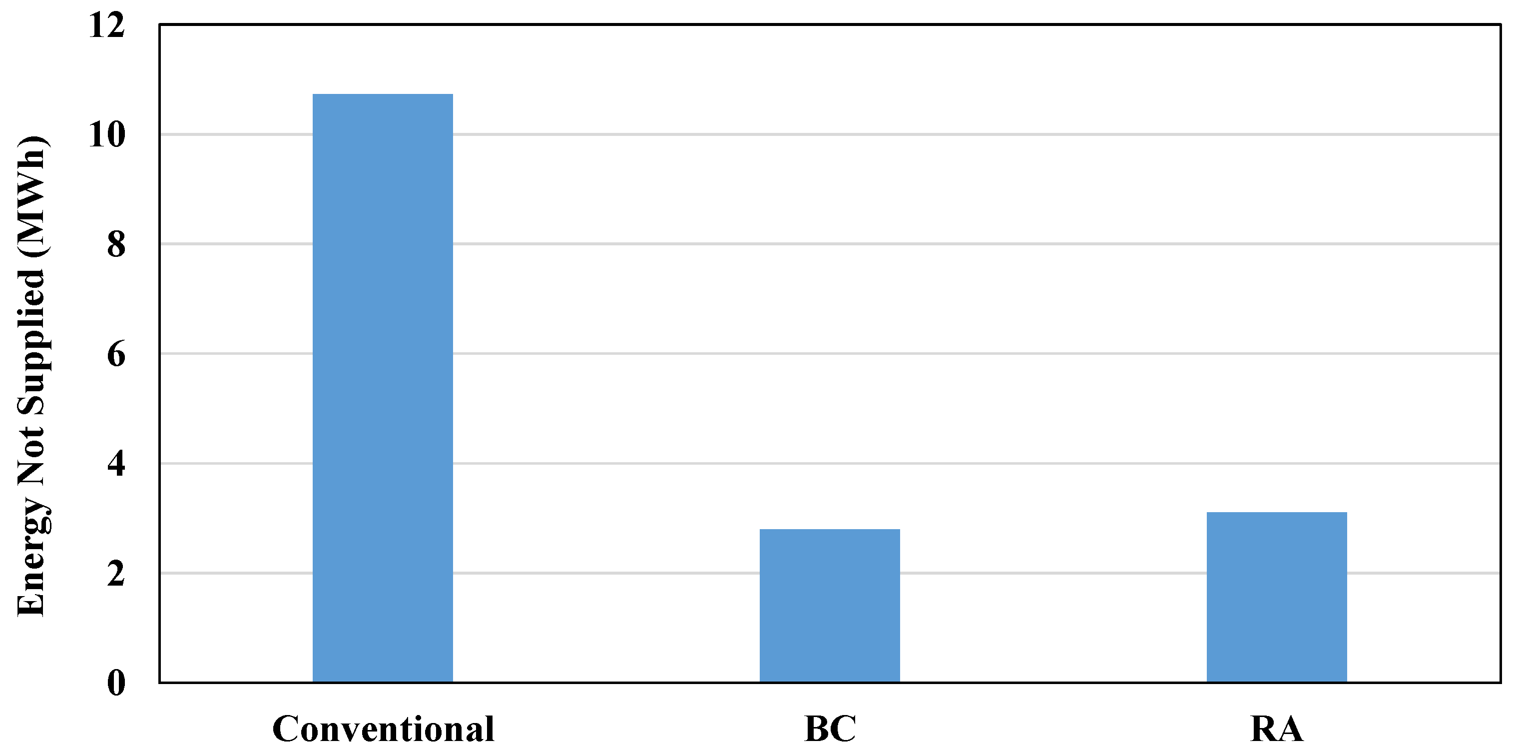
  • ScenarioS2: The MG is disconnected from the upstream grid in this scenario. Therefore, to supply system load as much as possible, in Scenario S2, the goal is to minimize the energy not supplied (ENS) of the grid.
    m i n E N S S 2 = i Ω b t Ω T P i , t , s 2 l s h

3.1. General Objective Function

In this case, the decision-maker tries to optimize active power losses and ENS simultaneously using the weighted sum method, as follows:
m i n O F = w s 1 × P s 1 l o s s + ( 1 w s 1 ) × E N S s 2
where w s is a weight coefficient which varies between 0 and 1 for different scenarios.
In the following, a novel model is introduced for the optimization constraints, which can handle both scenarios of the grid operation simultaneously.

3.2. Power Flow Constraints

The power flow constraints are an essential part of the MG operation [39]. In this study, these constraints are adopted by adding power output of different DERs, the grid operations in both connected and islanded mode, and the system’s configuration in each scenario.
  P i , t , s D G + P i , t , s G + P i , t , s l s h ( P i , t d + P i , t , s c h P i , t , s d c h ) = j Ω b ( X i j , t , s × P i j , t , s )       ;     i Ω b , t Ω T , s Ω S
Q i , t , s D G + Q i , t , s G + Q i , t , s l s h Q i , t d = j Ω b ( X i j , t , s × Q i j , t , s )                         ;     i Ω b , t Ω T , s Ω S
V m i n V i , t , s V m a x                         ;   i Ω b , t Ω T , s Ω S
P i j , t , s = + V i , t , s 2 g i j V i , t , s V j , t , s ( g i j c o s ( θ i j , t , s ) + b i j s i n ( θ i j , t , s ) )     ;     i Ω b , t Ω T , s Ω S
Q i j , t , s = V i , t , s 2 b i j V i , t , s V j , t , s ( g i j s i n ( θ i j , t , s ) b i j c o s ( θ i j , t , s ) )     ;     i Ω b , t Ω T , s Ω S
0 P i j , t , s 2 + Q i j , t , s 2 ( S i j m a x ) 2 ; i Ω b , t Ω T , s Ω S
X i j , t , s { 0 , 1 }           ;   ( i j ) Ω b
Constraints (19) and (20) show each bus’s active and reactive power balance, respectively. In these constraints, the index s represents the state of a system either in grid-connected or islanded mode. Constraint (21) indicates the voltage amplitude limit for each bus in different scenarios and operation periods. Constraints (22) and (23) represent the active and reactive power flowing through the lines. Constraint (24) limits the apparent power flow through the system branches. The binary variable X i j , t , s defined in (25) is the system’s configuration in each scenario of grid operation. It is worth mentioning that the binary variable X i j , t , s   in (25) plays a critical role as it defines the system’s configuration in different grid operation modes.

3.3. DG Capacity Constraints

The objective function of each scenario considers the capacity constraints of DGs.
0 P i , t , s D G P i D G C a p   i Ω d g , t Ω T , s Ω S
ε i D G × P i D G C a p Q i , t , s D G ε i D G × P i D G C a p     i Ω d g , t Ω T , s Ω S
where (26) limits the active power output of DGs. Considering the possibility of reactive power support by the DGs, the reactive power limits of DGs are shown in (27).

3.4. ESS Capacity Constraints

The state of charge, as well as charge/discharge constraints, of the ESSs are considered as follows in order to reduce losses and as well as energy not supplied.
S O C i , t , s = S O C i , ( t 1 ) , s + η c h   P i , t , s c h P i , t , s d c h η d c h     i Ω b , t Ω T , s Ω S
0 P i , t , s c h Z i , t , s c h × P i , t , s m a x     i Ω b E S S , t Ω T , s Ω S
0 P i , t , s d c h Z i , t , s d c h × P i , t , s m a x     i Ω b E S S , t Ω T , s Ω S
Z i , t , s c h + Z i , t , s d c h 1                                   i Ω b E S S , t Ω T , s Ω S
S O C i , t , s m i n S O C i , t , s S O C i , t , s m a x     i Ω b E S S , t Ω T , s Ω S
where (28) is charge/discharge and state of charge constraint of the ESS. Moreover, the maximum charge/discharge capacities of the ESS are given by (29) and (30), respectively. Z i , t , s c h and Z i , t , s d c h are binary variables that are equal to one and zero at the time of charging and discharging, respectively. Furthermore, (31) also states that the battery cannot be charged and discharged simultaneously. Finally, (32) is the charging capacity of ESSs.

3.5. Radiality Constraints

Due to the advantages of radial configuration, the MG operator tries to keep the radiality in both scenarios. The following two necessary conditions must be established to ensure a radial configuration for the MG.
  • No loops are formed in the grid.
  • All loads should be supplied.
To satisfy these conditions for both grid-connected and off-grid modes, this study utilizes the binary variable X i j , t , s , which defines the state of a line between buses i and j. To meet the first criterion of radiality, Equation (33) is adopted in this study [40].
1 2 i j Ω l X i j , t , s = n b 1
Moreover, the second condition is satisfied through the power flow constraints given in (19)–(25).

3.6. Uncertainty Handling

This part consists of two sections; first, in Section 3.6.1, the base case model is introduced, considering the objective function along with all constraints.
Then, in Section 3.6.2, the risk-averse model is introduced, considering the objective function and constraints.

3.6.1. Base Case Model

As aforementioned, the first optimization level solves the model in a base case, assuming that the uncertain parameter has no deviation from its predicted value. Therefore, for the proposed model of this study, the BC mathematical description is given as
O F b = m i n { ( w s 1 × P s 1 l o s s + ( 1 w s 1 ) × E N S s 2 ) } P i , t , s D G = P _ i D G i   Ω d g
Subject to (19)–(33)
where in (34), the objective function is minimized for both scenarios of grid operations, assuming that the forecasted value of DG capacity would not experience any deviation.

3.6.2. Risk-Averse Strategy

In the risk-averse strategy, the uncertainty of the uncertain parameter has an undesirable effect on the objective function of the problem. In other words, the actual realization of the uncertain parameter may increase the objective function of its base value. Therefore, this strategy seeks to find the maximum radius value of uncertainty parameters for the maximum and predetermined value for worsening objective function from its base. This means that the optimal values of the decision variables are determined so that the maximum possible uncertainty radius for the uncertain parameter is obtained for a certain amount of increase in the objective function.
All the equations are expressed in the state without uncertainty and are equal to their forecasted values. According to the RA strategy, decreasing DGs’ power outputs from their forecasted value changes objective function.
In fact, in this case, the aim is to see how much the radius of uncertainty can be magnified so the objective function does not get worse than a certain limit.
As mentioned, the parameter β is defined as the degree of tolerance of increasing the objective function relative to the base value due to undesirable uncertainties, the value of which is determined by the decision-maker.
For indicating the radius of the uncertainty parameter, which is considered as DGs’ output power in this paper, the risk-averse strategy should be used as follows:
m a x   Subject   to   ( 19 ) ( 33 )
O F O F b × ( 1 + β )
P i , t , s D G = ( 1 α ) × P _ i D G     i   Ω d g

4. Case Studies and Data

4.1. Data and Assumptions

The simulation results are presented in this section for different scenarios of grid operation. The model was simulated in GAMS software [41] using an SBB solver. The IEEE 33-bus network has been used as the test MG to investigate the model. The single-line diagram of the test MG is shown in Figure 1. This grid had a nominal voltage level of 12.66 kV and a total active and reactive load consumption of 3715 kW and 2300 kVAr, respectively. The minimum and maximum voltage magnitudes at each bus were 0.90 pu and 1.10 pu, respectively. The MG was connected to the upstream grid through Bus 1. It had 32 lines equipped with sectionalizers and five communication switches that are normally open. Based on the radiality constraint given in (33), the system reconfiguration always results in five open switches. The entire operation horizon was divided into four intervals, which is considered for the optimal scheduling of the system in grid-connected and off-grid modes. The grid load profile for each interval is depicted in Figure 2. The values given in this figure were multiplied to the aforementioned nominal demand of the MG. In this paper, two DGs and three energy storage units were considered. The locations of DGs were Buses 8 and 25 and the ESSs were connected to Buses 15, 27, and 32. The data of ESSs are given in Table 2, and DG capacity was equal to 1 MW.
Furthermore, in the RA case, the allowable deterioration in the objective function with respect to its BC value, i.e., β, was assumed to be 10%, which means the uncertainty of DGs’ output power is allowed up to the point where the objective function does not violate the threshold defined by (36).

4.2. Studied Cases

The performance of the proposed model is evaluated in different case studies:
First case study: This case optimizes the MG operation without consideration of network reconfiguration and impact of DERs (i.e., DGs and ESSs). This case is equivalent to the conventional energy scheduling models for MGs. Thus, it is called conventional for the rest of this paper. Note that this case study is only applicable when the MG is connected to the upstream network.
Second case study: This case study considers the network reconfiguration and impact of DERs in the BC (i.e., without considering uncertainty).
Third case study: The uncertainty of DG output affects the optimal results in this case study. This case study is the RA strategy.
In the following, the RA strategy is benchmarked against the conventional and BC approaches to show the importance of the study hypothesis. The performance of the model in both scenarios of grid-connected and off-grid modes is discussed.

5. Results and Discussion

In this section, first the simulations and numerical results are presented by assuming that the production of available resources equals the corresponding predicted value. Then, the results including DG and storage are given by considering the uncertainty on the predicted patterns, and finally, the evaluation of the obtained results in two cases, with and without uncertainty has been presented.
In the base case state, the DG power outputs are considered to be equal to the predicted values. The values of the objective function for the given value of ws are as follows:
In this case, from the first scenario (i.e., on-grid operation condition), the total energy loss will be 0.104 MWh and from the second scenario (i.e., the isolated operation mode) the ENS = 2.833 MWh.
In the risk averse case, the radius of uncertainty must be maximized to such an extent that the objective function increases to the tolerable level and becomes somewhat worse.
In this case, from the first scenario, energy loss will be 0.114 MWh and from the second scenario, ENS = 3.112 MWh. Given that the objective function has been deteriorated by 10%, the radius of the uncertainty parameter will be 0.04. Energy losses of the MG in on-grid mode are depicted for different case studies in Figure 3. As shown in Figure 3, in the presence of DERs, as well as a reconfiguration possibility in BC and RA cases, the losses decreased significantly compared to the conventional state, where there are no DERs and reconfiguration possibility in the on-grid operation mode of the MG. On the other hand, increasing the system robustness required importing power from the main grid, resulting in a slight increase in the power losses of the third case study, compared to case two.
The value of ENS for different case studies is shown in Figure 4. This figure demonstrates that the capability of the proposed framework in decreasing the ENS. A considerable reduction in ENS is obtained in both BC and RA cases. Moreover, it is evident from this figure that the value of ENS in the RA mode is more than that of the BC, which means that the decision-maker has to curtail some loads in order to improve the system robustness.
Figure 5 shows the optimal configuration of the studied network in the BC condition, both in on-grid and off-grid operation modes. Figure 5a reveals that in on-grid mode, the reconfiguration for reducing losses and reducing energy not supplied is associated with opening lines 6–7, 11–12, 13–14, 17–18, and 23–24. While in off-grid mode, as shown in Figure 5b, lines 2–19, 3–4, 12–22, and 13–14 are switched off, as in the off-grid mode, there is no connection to the upstream network by opening the line 1–2. This figure demonstrates how the network configuration can be changed in different operational circumstances.
In RA mode, the considered uncertainties are DG powers that appear as a coefficient ( 1 α ) in the existing DG output powers. In this case, the uncertainty radius (i.e., α) equals 0.04. The results given in Figure 6a show that the reconfiguration to reduce losses and reduce energy not supplied is associated with opening lines 26–6, 5–6, 21–8, 11–12, and 33–18 in the on-grid state. Furthermore, in Figure 6b, the network topology in off-grid mode is shown, where the lines 2–19, 12–22, 14–15, and 26–27 are disconnected, in addition to the main line 1–2. Furthermore, comparing Figure 5 and Figure 6 shows the effect of uncertainty on the optimal configuration of the network in different conditions.
The active power derived from the upstream network is compared for different case studies in Figure 7. As shown in this figure, a considerably higher amount of energy is imported from the upstream network in the conventional method (i.e., totally 11.22 MWh), compared to other BC and RA strategies with total imported energies of 3.83 and 4.28 MWh, respectively. This shows the importance of DGs in the load supply of MGs. Moreover, the amount of power derived from the main grid in the RA strategy is higher than that of the BC in all intervals. These results demonstrate that the system operator needs to import more active power from the main grid to improve the system robustness in the face of intermittency of renewable generation.
There is a similar analysis for the reactive power. According to the results obtained in Figure 8 for on-grid operation mode, the reactive power injected from the upstream network to the MG in the conventional case is higher than both BC and RA cases. In the conventional case, there are no DERs and network reconfiguration capability, but in both BC and RA cases, the MG is equipped with DERs and the network reconfiguration in on-grid mode is possible. These results also demonstrate the effect of the uncertainty in the DGs’ active power generations on the reactive power derived from the upstream network such that more reactive power is imported in the RA strategy compared to BC.
When the MG is disconnected from the main grid, DGs are the main source of power supply, while the flexibility in the ESS can increase the utilization of these energy sources. The energy output of DGs in the on-grid and off-grid modes is summarized in Table 3 for both BC and RA cases. It is obvious that more energy is supplied by these units in the off-grid mode. The output energy of DGs in this mode in the BC equals 8 MWh, while it is 7.68 MWh in the RA case. This means that increasing the system robustness requires more participation of loads in the RA case. Moreover, these results show a need to improve the system robustness even when the MG is operating in the islanded mode.
As mentioned, the SOC shows the available energy level of the battery and the amount of residual performance. Table 4 summarizes the state of charge of the ESS in different connection modes for the second and third case studies. In the case of being connected to the upstream network and BC, the available energy level of the battery is equal to 7%. This means that in this case, 93% of the battery energy was used. In the RA mode, the available energy level of the battery is 95%. This means that in this case, 5% of the battery energy was used. In this case, most of the network power is supplied through the upstream network. In other words, the decision-maker seeks a more robust source of energy supply in the RA case.
In the isolated, BC mode, the SOC of the battery is 36%, which indicates that 64% of the battery energy has been used, which is due to the disconnection of the network from the upstream network, showing that a large part of the power is supplied through the battery. In the RA mode, the SOC is zero. It means that almost 100% of the battery power was used, which was also predictable due to the uncertainty of the output power of DGs and their reduced power output.
Finally, the voltage profile of the MG (in the on-grid mode) for different operation periods is shown in Figure 9. It is observed that the voltage profile is decreased in the RA mode, which means the decrease in the output power of DGs in the RA mode affects the voltage profile inversely. Considering the radial topology of the network, reducing the output power of DGs in the RA mode affects the voltage profile.

6. Conclusions

In this paper, the operation of MGs in both on-grid and off-grid modes was studied. The uncertainty of DGs’ power output is handled by the IGDT approach. Reconfiguration of the network along with management of ESSs were considered as the flexibility options in the proposed method. This method gives the optimal configuration of the MG in both on-grid and off-grid modes.
According to the importance of the energy not supplied index in distribution grids and the effect of grid configuration on ENS, in addition to reducing losses, the problem of reconfiguration for reducing energy not supplied in the off-grid state was also investigated in this paper. Furthermore, the ESSs’ optimal charge/discharge was undertaken to reduce losses in the on-grid state and reduce the energy not supplied in the off-grid condition.
It was observed that by considering the uncertainty of the output power of DGs in the RA case, the voltage profile will decrease compared to the BC state, which is due to the supply of more power by the upstream network and consequently the voltage drop across the feeder. Unsupplied energy also increases, and power loss decreases in the RA case compared to the BC. The effect of uncertainty on other system parameters (e.g., market price and weather forecast) on the grid characteristics can be considered as a future study.
The following subjects will be the focus of future works in this area:
  • Considering the possibilistic nature of the loads and comparing the results obtained from the IGDT technique with other methods of modeling uncertainty, such as the possibilistic programming method.
  • Examining the use of other flexibilities such as demand response as an option to reduce the unsupplied energy.
  • Considering the voltage dependent load model for all demand types, as in off-grid operation mode the behavior of loads is an important factor.

Author Contributions

Conceptualization, A.R.; methodology, S.R. and A.R.; software, S.R. and N.B.; validation, A.R. and S.N.; formal analysis, S.R., N.B., S.N. and A.R.; investigation, A.R. and S.N.; resources, A.R.; data curation, A.R.; writing—original draft preparation, S.R.; writing—review and editing, A.R., S.N. and A.S.; visualization, S.R. and A.R.; supervision, A.R. and A.S.; project administration, A.R. All authors have read and agreed to the published version of the manuscript.

Funding

This research received no external funding.

Data Availability Statement

Data are contained within the article.

Conflicts of Interest

The authors declare no conflict of interest.

Nomenclature

Sets
Ω b Set of all nodes
Ω b E S S Set of buses equipped with ESS
Ω T Set of operation period
Ω s Set of scenarios (on-grid, off-grid)
Ω l Set of branches
Ω d g Set of DG installed buses
Indices
i,jIndex of System buses
sIndex for Scenario (on-grid and off-grid)
TIndex of Operation period
Variables and Parameter
P i , t , s l s h Active power of load disconnected from the grid in MG’s isolated mode
Q i , t , s l s h Reactive power of load disconnected from the grid in MG’s isolated mode
E N S Energy not supplied
P s l o s s Active power losses
P i , t , s G Active power generated by the post
Q i , t , s G Reactive power generated by the post
P i , t d Active load of bus i
Q i , t d Reactive load of bus i
P i , t , s D G Generation power of the DG installed in the bus i
Q i , t , s D G Reactive power generated by the buses connected to the DG
P i D G c a p Capacity of DGs
ε i D G Maximum limit of reactive power exchange by the DG unit located in i-th bus
P _ i D G Maximum predicted value of active power in DG connected bus
β Degree of tolerance of increasing the objective function relative to the base value
P i , t , s c h Battery charge capacity
P i , t , s d c h Battery discharge capacity
P i , t , s m a x Maximum limit of battery capacity
S O C i , t , s Energy level available in the battery
P i , t , s m i n Minimum limit of battery capacity
η c h Charging efficiency of ESS
η d c h Discharging efficiency of ESS
Z i , t , s c h Binary variable to model charging state of ESS
Z i , t , s d c h Binary variable to model discharging state of ESS
P i j , t , s Active power flow of ij-th branch
Q i j , t , s Reactive power flow of ij-th branch
V i , t , s Voltage amplitude of i-th bus
V m i n Minimum voltage amplitude
V m a x Maximum voltage amplitude
g i j Conductance of ij-th branch
b i j Susceptance of the ij-th branch
X i j , t , s The binary variable representing the status of the line between buses i and j

References

  1. Yin, C.; Wu, H.; Locment, F.; Sechilariu, M. Energy management of DC microgrid based on photovoltaic combined with diesel generator and supercapacitor. Energy Convers. Manag. 2017, 132, 14–27. [Google Scholar] [CrossRef]
  2. Dulău, L.I.; Bică, D. Optimization of generation cost in a microgrid. Procedia Manuf. 2018, 22, 703–708. [Google Scholar] [CrossRef]
  3. Palizban, O.; Kauhaniemi, K.; Guerrero, J. Microgrids in active network management—Part I: Hierarchical control, energy storage, virtual power plants, and market participation. Renew. Sustain. Energy Rev. 2014, 36, 428–439. [Google Scholar] [CrossRef] [Green Version]
  4. Nikkhah, S.; Rabiee, A. A Joint Energy Storage Systems and Wind Farms Long-Term Planning Model Considering Voltage Stability. In Operation, Planning, and Analysis of Energy Storage Systems in Smart Energy Hubs; Springer: Cham, Switzerland, 2018; pp. 337–363. [Google Scholar] [CrossRef]
  5. Li, Y.; Feng, B.; Li, G.; Qi, J.; Zhao, D.; Mu, Y. Optimal distributed generation planning in active distribution networks considering integration of energy storage. Appl. Energy 2018, 210, 1073–1081. [Google Scholar] [CrossRef] [Green Version]
  6. Del Granado, P.C.; Wallace, S.W.; Pang, Z. The value of electricity storage in domestic homes: A smart grid perspective. Energy Syst. 2014, 5, 211–232. [Google Scholar] [CrossRef]
  7. Zhang, K.; Li, J.; He, Z.; Yan, W. Microgrid energy dispatching for industrial zones with renewable generations and electric vehicles via stochastic optimization and learning. Phys. A Stat. Mech. Appl. 2018, 501, 356–369. [Google Scholar] [CrossRef]
  8. Del Granado, P.C.; Pang, Z.; Wallace, S.W. Synergy of smart grids and hybrid distributed generation on the value of energy storage. Appl. Energy 2016, 170, 476–488. [Google Scholar] [CrossRef] [Green Version]
  9. Iris, Ç.; Lam, J.S.L. A review of energy efficiency in ports: Operational strategies, technologies and energy management systems. Renew. Sustain. Energy Rev. 2019, 112, 170–182. [Google Scholar] [CrossRef]
  10. Rahmani-Andebili, M. Simultaneous placement of DG and capacitor in distribution network. Electr. Power Syst. Res. 2016, 131, 1–10. [Google Scholar] [CrossRef]
  11. Iris, Ç.; Lam, J.S.L. Optimal energy management and operations planning in seaports with smart grid while harnessing renewable energy under uncertainty. Omega 2021, 103, 102445. [Google Scholar] [CrossRef]
  12. Chen, C.; Duan, S. Optimal allocation of distributed generation and energy storage system in microgrids. IET Renew. Power Gener. 2014, 8, 581–589. [Google Scholar] [CrossRef] [Green Version]
  13. Nair, A.S.; Hossen, T.; Campion, M.; Selvaraj, D.F.; Goveas, N.; Kaabouch, N.; Ranganathan, P. Multi-Agent Systems for Resource Allocation and Scheduling in a Smart Grid. Technol. Econ. Smart Grids Sustain. Energy 2018, 3, 15. [Google Scholar] [CrossRef] [Green Version]
  14. Phommixay, S.; Doumbia, M.L.; St-Pierre, D.L. Review on the cost optimization of microgrids via particle swarm optimization. Int. J. Energy Environ. Eng. 2019, 11, 73–89. [Google Scholar] [CrossRef] [Green Version]
  15. Bouchekara, H.R.E.-H.; Javaid, M.S.; Shaaban, Y.A.; Shahriar, M.S.; Ramli, M.A.M.; Latreche, Y. Decomposition based multiobjective evolutionary algorithm for PV/Wind/Diesel Hybrid Microgrid System design considering load uncertainty. Energy Rep. 2020, 7, 52–69. [Google Scholar] [CrossRef]
  16. Zakir, M.; Sher, H.A.; Arshad, A.; Lehtonen, M. A fault detection, localization, and categorization method for PV fed DC-microgrid with power-sharing management among the nano-grids. Int. J. Electr. Power Energy Syst. 2021, 137, 107858. [Google Scholar] [CrossRef]
  17. Zakir, M.; Arshad, A.; Sher, H.A.; Al-Durra, A. Design and implementation of a fault detection method for a PV-fed DC-microgrid with power control mechanism. IET Electr. Power Appl. 2022. [Google Scholar] [CrossRef]
  18. Gholami, A.; Shekari, T.; Aminifar, F.; Shahidehpour, M. Microgrid Scheduling With Uncertainty: The Quest for Resilience. IEEE Trans. Smart Grid 2016, 7, 2849–2858. [Google Scholar] [CrossRef]
  19. Kumar, K.P.; Saravanan, B. Recent techniques to model uncertainties in power generation from renewable energy sources and loads in microgrids—A review. Renew. Sustain. Energy Rev. 2017, 71, 348–358. [Google Scholar] [CrossRef]
  20. Ben-Haim, Y. Info-Gap Decision Theory: Decisions under Severe Uncertainty; Academic Press: Cambridge, MA, USA, 2006. [Google Scholar]
  21. Majidi, M.; Mohammadi-Ivatloo, B.; Soroudi, A. Application of information gap decision theory in practical energy problems: A comprehensive review. Appl. Energy 2019, 249, 157–165. [Google Scholar] [CrossRef] [Green Version]
  22. Zhao, J.; Wan, C.; Xu, Z.; Wang, J. Risk-Based Day-Ahead Scheduling of Electric Vehicle Aggregator Using Information Gap Decision Theory. IEEE Trans. Smart Grid 2015, 8, 1609–1618. [Google Scholar] [CrossRef]
  23. Sarhadi, S.; Amraee, T. Robust dynamic network expansion planning considering load uncertainty. Int. J. Electr. Power Energy Syst. 2015, 71, 140–150. [Google Scholar] [CrossRef]
  24. Kazemi, M.; Mohammadi-Ivatloo, B.; Ehsan, M. Risk-based bidding of large electric utilities using Information Gap Decision Theory considering demand response. Electr. Power Syst. Res. 2014, 114, 86–92. [Google Scholar] [CrossRef]
  25. Chen, K.; Wu, W.; Zhang, B.; Sun, H. Robust Restoration Decision-Making Model for Distribution Networks Based on Information Gap Decision Theory. IEEE Trans. Smart Grid 2014, 6, 587–597. [Google Scholar] [CrossRef]
  26. Murphy, C.; Soroudi, A.; Keane, A. Information Gap Decision Theory-Based Congestion and Voltage Management in the Presence of Uncertain Wind Power. IEEE Trans. Sustain. Energy 2015, 7, 841–849. [Google Scholar] [CrossRef] [Green Version]
  27. Kavousi-Fard, A.; Zare, A.; Khodaei, A. Effective Dynamic Scheduling of Reconfigurable Microgrids. IEEE Trans. Power Syst. 2018, 33, 5519–5530. [Google Scholar] [CrossRef]
  28. Acosta, J.A.; Cornick, K.J. Computer Models for Complex Plant & System Based on Terminal Measurements. IEEE Power Eng. Rev. 1989, 9, 101. [Google Scholar]
  29. Baran, M.E.; Wu, F.F. Network Reconfiguration in Distribution Systems for Loss Reduction and Load Balancing. IEEE Power Eng. Rev. 1989, 9, 101–102. [Google Scholar] [CrossRef]
  30. Zin, M.; Ferdavani, A.K.; Bin Khairuddin, A.; Naeini, M.M. Two Circular-Updating Hybrid Heuristic Methods for Minimum-Loss Reconfiguration of Electrical Distribution Network. IEEE Trans. Power Syst. 2012, 28, 1318–1323. [Google Scholar] [CrossRef]
  31. Jabr, R.A.; Singh, R.; Pal, B.C. Minimum Loss Network Reconfiguration Using Mixed-Integer Convex Programming. IEEE Trans. Power Syst. 2012, 27, 1106–1115. [Google Scholar] [CrossRef]
  32. Rao, R.S.; Narasimham, S.V.L.; Raju, M.R.; Rao, A.S. Optimal Network Reconfiguration of Large-Scale Distribution System Using Harmony Search Algorithm. IEEE Trans. Power Syst. 2010, 26, 1080–1088. [Google Scholar] [CrossRef]
  33. Srinivasa Rao, R.; Ravindra, K.; Satish, K.; Narasimham, S.V.L. Power Loss Minimization in Distribution System Using Network Reconfiguration in the Presence of Distributed Generation. IEEE Trans. Power Syst. 2013, 28, 317–325. [Google Scholar] [CrossRef]
  34. Ding, T.; Lin, Y.; Bie, Z.; Chen, C. A resilient microgrid formation strategy for load restoration considering master-slave distributed generators and topology reconfiguration. Appl. Energy 2017, 199, 205–216. [Google Scholar] [CrossRef]
  35. Thakar, S.; Vijay, A.S.; Doolla, S. System reconfiguration in microgrids. Sustain. Energy Grids Netw. 2019, 17, 100191. [Google Scholar] [CrossRef]
  36. Park, J.-Y.; Kim, Y.-J.; Lu, X. New Analytical Model of Microgrid Frequency and Voltage Variations Due to Network Reconfiguration. IEEE Trans. Smart Grid 2020, 12, 905–908. [Google Scholar] [CrossRef]
  37. Soroudi, A.; Amraee, T. Decision making under uncertainty in energy systems: State of the art. Renew. Sustain. Energy Rev. 2013, 28, 376–384. [Google Scholar] [CrossRef] [Green Version]
  38. Rabiee, A.; Nikkhah, S.; Soroudi, A.; Hooshmand, E. Information gap decision theory for voltage stability constrained OPF considering the uncertainty of multiple wind farms. IET Renew. Power Gener. 2017, 11, 585–592. [Google Scholar] [CrossRef]
  39. Nikkhah, S.; Nasr, M.-A.; Rabiee, A. A Stochastic Voltage Stability Constrained EMS for Isolated Microgrids in the Presence of PEVs Using a Coordinated UC-OPF Framework. IEEE Trans. Ind. Electron. 2020, 68, 4046–4055. [Google Scholar] [CrossRef]
  40. Lavorato, M.; Franco, J.F.; Rider, M.J.; Romero, R. Imposing radiality constraints in distribution system optimi-zation problems. IEEE Trans. Power Syst. 2011, 27, 172–180. [Google Scholar] [CrossRef]
  41. Soroudi, A. Power System Optimization Modeling in GAMS; Springer: Cham, Switzerland, 2017; pp. 1–295. [Google Scholar] [CrossRef]
Figure 1. Single-line diagram of the test MG.
Energies 15 05369 g001
Figure 2. Grid load profile in different time intervals.
Energies 15 05369 g002
Figure 3. Energy losses in different case studies (on-grid mode).
Energies 15 05369 g003
Figure 4. Energy not supplied in different case studies (off-grid).
Energies 15 05369 g004
Figure 5. Optimal configuration of the network in BC: (a) on-grid operation mode; (b) off-grid operation mode.
Energies 15 05369 g005
Figure 6. Optimal configuration of the network in RA: (a) on-grid operation mode; (b) off-grid operation mode.
Energies 15 05369 g006
Figure 7. Imported active power from the main grid in different cases (on-grid operation mode).
Energies 15 05369 g007
Figure 8. Imported reactive power from the main grid in different cases (on-grid operation mode).
Energies 15 05369 g008
Figure 9. Voltage profile of the MG in BC and RA case studies (on-grid): (a) interval T1; (b) interval T2; (c) interval T3; (d) interval T4.
Energies 15 05369 g009
Table 1. Taxonomy of available literature on MG scheduling.
Ref.ReconfigurationDER PlacementObjective FunctionsUncertainty Modeling ApproachMG State
DGESSPower LossReliabilityOn-GridOff-Grid
[1]
[2]
[13]
[14]
[15]
[18]
[19]
[27]
[36]
This study
Table 2. The data of ESS units.
Parameter S O C i , t , s m a x   ( MWh ) S O C i , t , s m i n   ( MWh ) η c h η d c P i , t , s m a x   ( MW )
Value0.500.000.950.950.10
Table 3. Total energy outputs of DGs for different operation modes of MGs.
Energy Injection (MWh)
Case StudyBCRA
On-grid7.006.61
Off-grid8.007.68
Table 4. State of charge of the ESS in different connection modes for different case studies.
Case StudyBCRA
On-grid7%95%
Off-grid36%0%
Publisher’s Note: MDPI stays neutral with regard to jurisdictional claims in published maps and institutional affiliations.

