Abstract
This paper deals with the proposition of improvement in the performance of a heat source by modification of its structure and by deriving a dedicated control system. Traditional heat sources consist of a single heater of high nominal power, but slow dynamics, that is regulated by a single closed loop control system. In this paper, an existing heater serially-connected with a supplemental heater with low nominal power but fast dynamics is proposed. A dedicated control system was derived with two active disturbance rejection controllers (ADRC) implemented in the habituating control structure. The proposed solution was validated using a virtual commissioning procedure where the heating system was simulated in the SIEMENS® Simit v10.3 industrial software, and ADRC controllers were implemented in SIEMENS® PLCSIM Advanced using dedicated library function blocks. The results showed the superiority of the proposed approach in comparison with the traditional single closed loop solution. The proposed dedicated habituating control system provided better robustness to the changes in dynamics of a heat source and to the measurement noise. At the same time, it will ensure lower (or in some cases comparable) values of popular closed loop performance indices.
1. Introduction
The heat source (HS) is one of the most important parts of each heat distribution network (HDN). It is responsible for providing the amount of energy that is currently required by heat receiver(s) (HR). Thus, the HS must be designed to ensure a high level of resilience because it must supply a desired heat flux in the presence of significant variations in heat demand. Consequently, the design of an HS control system is a challenging task because it must ensure high flexibility, but at the same time, it should provide fast tracking for potential variations of heat demand. It should also prevent an excessive or insufficient energy supply, without over or under heating. The first phenomenon always results in excessive use of energy or/and damage of the final product, while the latter leads to an unnecessarily prolonged heating time that results in lowering the production efficiency [1,2]. Usually a single HS supplies a more or less complex HDN that can consist of a number of HRs operating in different and varying conditions. High efficiency of a power supply requires that the HS should be oversized to cope with transient increases in power consumption. This oversizing prevents the saturation of HS in cases of very high increases in heat demand. This saturation results in long transients that significantly limit the efficiency of control in the whole HDN. However, apart from this benefit, an oversized HS is a source of another significant drawback—it exhibits slow dynamics that also limit the efficiency of control but in a different way. The dynamics of an HS are always a limitation when the fast tracking of variations in head demand is expected, and even advanced adaptive control systems are not able to cope with this difficulty [3,4]. Thus, the redesign of an HS combined with a properly designed HS control system can be an effective remedy for this limitation.
In this paper, a modified traditional HDN configuration with an HS is proposed that consists of a single heater with slow dynamics by adding an additional heater with significantly faster dynamics in the series. Then, a novel HS allows for the separate operation of both heaters and the use of the slow heater for adjusting the slowly-varying operating point, while fast heater can be used for the current rejection of fast-varying disturbances resulting from variations in heat demand. These obvious benefits resulting from separating the slow and fast dynamics between two heaters are achievable only when this modified HS is controlled by a dedicated control system because, in this configuration, the HS represents a double-input single output dynamical process. Thus, for this purpose, it is proposed to apply a habituating control structure that is dedicated to such problems. For the considered case, the habituating control structure requires the application of two cooperating controllers to ensure the efficient operation of both heaters. Even if both controllers are general-purpose (such as PI, PID, etc.), their tuning requires special attention to improve cooperation and reduce mutual interference. However, more advanced controllers could be proposed for further improvement in control performance, and in this paper, two ADRC (active rejection disturbance controllers) were used.
For the last several years, active disturbance rejection controllers (ADRC) [5,6] in their linear form [7,8] gained a large popularity among researchers and practitioners. Its popularity results from the fact that an ADRC can be derived without detailed knowledge on the model of the controlled process because it efficiently compensates not only for external disturbances but also for unknown process dynamics. This feature results from the fact that an ADRC uses an extended state observer (ESO) that allows for easy on-line estimation of the so-called total disturbance function that represents both the process dynamics and the external disturbances. This approach simplifies the derivation of ADRC control law because then even complex and nonlinear processes can be represented in the form of a serial connection of integrators [8]. Another advantage of ADRCs is the possibility of intuitive tuning [7,9]. The user only has to adjust controller and observer bandwidths and, when necessary, the so-called scaling factor. Its application is supported by the dedicated toolbox for SIMULINK implementation [10] and for industrial applications [11], also by dedicated general purpose function blocks for PLC-based implementation [12,13]. ADRCs also proved their ability to ensure energy-efficient control, e.g., [14,15].
This paper is organized as follows. First, the problem is stated and the modification of the HS is proposed. Then, how the suggested ADRC-based habituating control structure was developed and applied as the HCS for the considered case is shown. Finally, it is described how virtual commissioning was applied for the validation of the proposed concept, and the results showing its superiority are presented.
2. Motivation and Statement of the Problem
As it was already said, a traditional HS consists of a single heating unit (HU) with slow dynamics that warms flowing liquid to transfer the desired amount of energy to the HR. This configuration is schematically shown in Figure 1, which represents the existing part of the laboratory heat exchange and distribution setup. The liquid (municipal water) of measured inlet temperature Tin (°C) flows into the HU (electric flow heater of the volume V = 1.6 (L)) with flow rate F, stabilized by adjusting the control valve V by the dedicated flow controller FC at the desired set point Fsp. Power of the heater is manipulated by adjusting the value Ph (within 0–100% of Pnom = 12 (kW)) and hot liquid flows out to HR with the measured temperature Tout (°C).
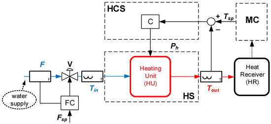
Figure 1.
Schematic diagram of the traditional configuration of an HS. The heating system (HS) consists of a single heating unit (HU) with slow dynamics. The heating control system (HCS) consists of a single controller I operating in a single closed loop structure.
When the amount of heat transferred to HR is to be controlled by adjusting the outlet temperature Tout, the control goal for the heating control system (HCS) is to stabilize this temperature at the set point Tsp, which is adjusted by the master controller (MC) based on the current heat demand required in HR. Then, the flow rate F is determined by a user or by a supervisory control system and remains constant or only slightly varies. In such cases, HCS usually consists of a single controller C operating in a single closed loop structure.
The motivation for this work is the fact that, in such a conventional HS configuration, when a large change in heat demand appears, the slow dynamics of the HU are a significant difficulty for the HCS. Namely, the fast tracking of variations in heat demand indicated by changes of Tsp is naturally limited by this dynamics, and even an advanced HCS fails to ensure this requirement. This fact significantly limits the performance of the MC and consequently of the whole HDN.
The statement of the problem considered in this paper is to manage this difficulty by proposing the modification of the HS as it is shown in Figure 2 and then propose a dedicated HCS structure. This problem can be solved if the existing HU (now labelled as HU1) is supplemented with the other (HU2) connected serially. In this configuration, HU1 (having higher nominal heating power Pnom1 but slower dynamics) is responsible for adjusting the required operating conditions for the HS. The newly added HU2 (having lower nominal heating power Pnom2 << Pnom1 but significantly faster dynamics) is responsible for the fast rejection of current variations in heat demand. Now, both HUs must be separately controlled by adjusting their power supplies, respectively, Ph1 (within 0–100% of Pnom1) and Ph2 (within 0–100% of Pnom2), and this goal should be achieved by the proper redesign of HCS that provides a proper and correlated adjustment of both power supplies, which consequently ensures the desired dynamical properties of HS faster compared to the configuration shown in Figure 1.
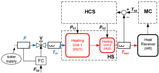
Figure 2.
Schematic diagram of the proposed modification of HS. The new HS consists of two serially connected heating units (HU1 and HU2), and it becomes a double-input single-output dynamical system. Then, the dedicated HCS must be applied to cope with this control problem.
3. ADRC-Based Habituating Control
As it was said, modification of the HS proposed in a previous section requires a properly designed HCS. In this paper, it was proposed to solve this problem by designing the HCS as a habituating control structure, with two controllers designed based on the ADRC framework.
3.1. Habituating Control Structure and Its Application for Proposed HCS
The habituating control structure is dedicated to controlling multi-input single output processes [16,17]. Basically, this concept was proposed to prevent transient and/or steady state output unreachability in the presence of input saturation. Additionally, habituating control is able to ensure the cost-efficient control of the processes, for which some inputs can be distinguished as low-cost and the others as higher-cost. It was also suggested to minimize increasing higher-cost inputs by substituting their action by changing low-cost inputs. Then, in long term operation, significant cost reduction can be observed. The habituating control structure received noticeable attention, both in terms of direct control design, e.g., [16,18,19], and of stability analysis (Ramirez-Alvarez et. al., 2004).
Apart from the aforementioned benefits resulting from the application of habituating control architecture for regulating multi-input single output processes, Alvarez-Ramirez et al. [20] pointed to another advantage that is potentially achievable in cases when one can distinguish between the inputs of relatively fast dynamics and those of slow dynamics. Current process control in the presence of disturbances should then be realized by changing the inputs of fast dynamics. Slow dynamic inputs should be used for adjusting the operating point and should be changed only in the presence of large variations of disturbances or when the saturation of the fast input is possible. This motivation clearly shows that the habituating control structure is a suitable framework for designing the HCS operating modified HS shown in Figure 2.
Figure 3 shows the proposed configuration of that HCS that consists of two controllers (C1 and C2) operating in a habituating control structure. The control goal was defined to keep the outlet temperature of heated liquid Tout equal to its set point Tsp. C2 operates the HU2 of faster dynamics and lower nominal power Pnom2 by adjusting Ph2. It ensures the fast rejection of variations of Tsp resulting from varying heat demands in the heat receiver HR. At the same time, CS1 operates the HU1 of slow dynamics and higher nominal power Pnom1 >> Pnom2. It ensures that at any operating point adjusted by Ph1, CS2 always operates around Ph2 = Ph2sp = 50% of Pnom2; thus, the potential saturation of Ph2 limiting cumulative efficiency of HS is avoided.
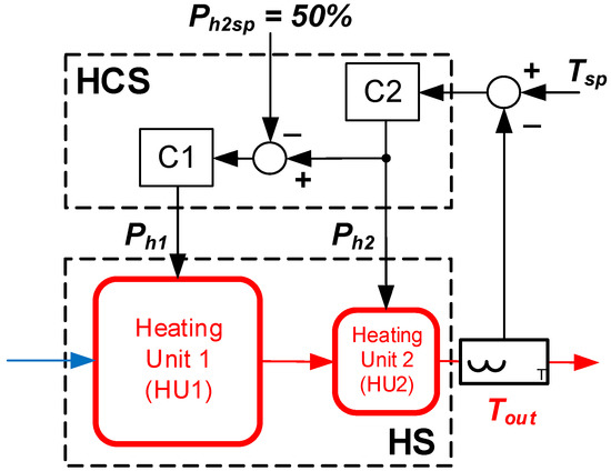
Figure 3.
Schematic diagram of the proposed HCS that consists of two controllers (C1 and C2) operated in the habituating control structure.
3.2. Design of Controllers C1, C2 Based on ADRC Framework
In this paper, it was proposed to design C1 and C2 controllers that operate in the structure shows in Figure 3 based on the ADRC framework. Both controllers must be derived using the SISO approach (single-input single output), and for this case, the ADRC design for processes of the relative degree r ≥ 1 was based on the simplified model , where Y is the controlled process output, u is the manipulating input, h represents the so-called total disturbance that lumps all the modelling uncertainties, and b0 is the adjustable scaling parameter [5,6,8]. In general, the simplified process model can be represented in the canonical (r + 1)th order extended state space form:
where consists of (r + 1) state variables, from which the additional represents the unknown dynamics of the total disturbance h, , , and . After the implementation of the extended state observer (ESO) in the unified form of the Luenberger observer (with denoting respective values of computed by ESO and L denoting adjustable gains of ESO), it is obtained by the following:
and substituting h = , assuming the constant set point Ysp and linear r-th order closed loop reference model of the r-th order:
the final general form of ADRC is derived as:
The ESO given by Equation (2) must be tuned by adjusting its gains L based on the characteristic polynomial. It is usually suggested that the dynamics of the ESO should be 3 10 times faster than the desired closed loop dynamics [7,21]. Additionally, tuning ADRC for a higher r > 1 order requires adjusting r tuning parameters: kp and kdj (j = 1 r−1).
For the considered case presented in Figure 3, it was advised that both controllers C1 and C2 should be designed as first order ADRC, which is justified as follows. HU2 has fast dynamics; thus, compared to the dynamics of HU1, it can be considered as a first order lag. Thus, for this kind of dynamics, there is no use applying an ADRC of an order greater than one. HU1 has slow dynamics, but in the habituating control structure, its goal is to adjust the operating point of the double-heater HS in the presence of fluctuations in heat demand. Thus, it should be operated by C1 smoothly to avoid the undesirable disturbance of HU2 and consequently of Tout. For this reason, an excessive higher order derivative action is not desirable.
Based on Equations (1)–(4), the first order ADRC control law has the final form:
with ESO in the form:
Tuning based on the adjustment of controller and observer bandwidths and the scaling factor requires the adjustment of ωc, ωo = (3 10)·ωc, and b0, respectively. Then, the relationships can be applied as: kp = ωc, l1 = 2·ωo and l2 = ω2o.
4. Implementation and Validation
In this paper, validation of the proposed concept was performed by virtual commissioning, in which a simulated (virtual) HS was connected to a simulated PLC where the proposed ADRC-based habituating control structure was implemented. This approach preserved the full industrial functionality of the simulated PLC compared to the hardware unit, and it did not require any additional hardware interface that was needed when real PLC was used in virtual commissioning and connected to a simulated process. In virtual commissioning, it is possible to validate not only the concept and tuning of the control strategy but also its practical PLC-based implementation with all the required functionalities, including full hardware configuration. Additionally, when a detailed model of the process is accessible for virtual commissioning, it is possible to test not only the control system, but also possible modifications in the process itself, such as location of sensors, adding additional components in the process (process vessels, heaters, heat exchangers, control valves, etc.). Then, the optimal configuration of both process and its control system can be derived and then applied in the practice. This approach is widely used for manufacturing systems [22,23,24], and it is also applied for industrial automation [2,4,25,26].
4.1. Modelling of HS and Its Implementation for Virtual Commissioning
The model of the considered HS was partially based on the model of the existing electric flow heater operating as a part of the laboratory heat exchange and distribution setup. This model was based on the first principal approach, with additional terms representing the dynamics of sensors, of electric heaters, and of the other unknown phenomena taking place in real systems. Its major part consists of the nonlinear first order dynamical equation:
where cs = 4200 J/(kg °C) is a water specific heat, ρs = 1 (kg/L) is water density, and V1 = 1.6 (L) is the volume of the heater. Constant coefficients in (7) are used to unify the units (flow rate F from (L/min) to (L/sec) and power supply Ph1 from (% of nominal power Pnom1) to (W)). Tin (°C) denotes the measurable temperature at the inlet of the existing electric flow heater, while (°C) is the unmeasurable temperature that stands as the output of the first principal part of the model (7) and, at the same time, as the input to additional dynamics described by the transfer function:
where (°C) denotes the temperature at the outlet of the electric flow heater, k is the gain that depends on the power Ph1, time constants τ1, τ2 represent additional dynamics dependent on the flow rate F, and τ0 is the dead time. Relationships that describe variations of the parameters of the additional dynamics (8) according to changes of the operating point have been identified based on real measurement data and are expressed as:
The identification procedure was based on measurement data (responses to consecutive step changes of Ph1) collected for different flow rates F. Then, for this data, the identification of the parameters of the transfer function (8) was made for each flow rate value using the fminsearch() MATLB function. Finally, using a different class of approximating functions, the Curve Fitting Toolbox from MATLB was used to obtain the final approximating Equation (9).
The modelling accuracy of models (7)–(9) is presented in Figure 4, in the presence of consecutive step changes of power Ph1 and flow rate F. The results show a very high modeling accuracy that authorizes the use of this model in further research as HU and HU1, depending on the considered structure of the HCS.
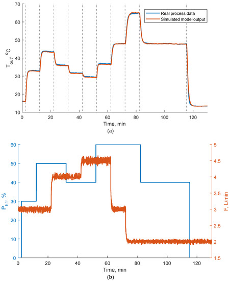
Figure 4.
Modelling accuracy of models (7)–(9) (a) in the presence of consecutive step changes of power Ph1 and flow rate F (b).
Note that when the HU modelled by (7)–(9) operates in the traditional configuration shown in Figure 1, the measurable and controlled temperature Tout is directly equal to the modelled temperature Tout1. For the proposed modification of the HS shown in Figure 2, the modelled temperature Tout1 of liquid outflowing from HU1 is unmeasurable for HCS, and it stands as the inlet temperature for HU2.
As the second additional HU2, an electric flow heater of significantly smaller volume V2 = 0.25 (L) and lower nominal power Pnom2 = 4 (kW) was proposed. Due to the smaller volume, its dynamics are much faster compared to the heater described by models (7)–(9), which authorized its use as HU2 in the modified structure shown in Figure 2. These fast dynamics also justify the simpler model given in the form of the first order dynamical equation based on the first principal modelling:
where the notation is consistent with the notation used for models (7)–(9). This heater operates only in modified HS as HU2; thus, the modelled temperature Tout1 is included in Equation (10) as the inlet temperature, and Tout is the measurable and controlled temperature of the liquid outflowing from HS.
Both models of heaters were implemented in SIEMENS® Simit v10.3 industrial software as a simulator of the proposed double-heater HS. This software is dedicated both to the process simulation and emulation of the PLC connection to the real sensors and actuators, along with scaling functions and range limitations. Figure 5 shows the connection between both models encapsulated in two separated blocks. Note that both blocks have the same unified inputs (flow rate F, heating power Ph, inlet temperature Tin) and the same output (outlet temperature Tout), but each of them includes a different model—HU1 encapsulates more complex models ((7)–(9)), while HU2 encapsulates a simpler model (10).
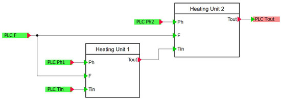
Figure 5.
Schematic diagram of the simulator of the double-heater HS implemented in SIEMENS® Simit v10.3 industrial software as the connection of two separated HU.
4.2. PLC-Based Implementation of ADRC-Based HCS
The ADRC-based habituating control structure proposed as the HCS shown in Figure 3 was developed in the PLC SIEMENS® S7-1500 simulator implemented in the SIEMENS® PLCSIM Advanced industrial software dedicated to use in the virtual commissioning of industrial control systems. The direct implementation of both ADRC controllers was conducted using the ADRC general-purpose library function block, described in detail in [13] and dedicated to use in industrial control systems based on the SIEMENS® PLC family. This block has flexibility and generality comparable to the general-purpose PID library function blocks; thus, it can be considered as the alternative for practitioners who implement industrial control systems. It allowed for the fast and convenient implementation of ADRC controllers of first to third order, and it encapsulated all necessary calculations jointly with additional functionalities required in industrial practice, such as bump-less switching, output constraints, anti-windup action, and anti-backoff action preventing from derivative backoff. Figure 6 shows a part of the PLC program representing the connection between the two ADRC controllers (C1 and C2, see Figure 3).
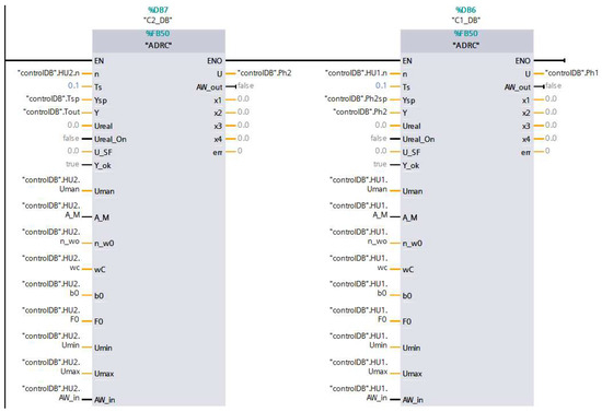
Figure 6.
Schematic diagram of the PLC-based implementation of the control program representing the proposed ADRC-based habituating control structure.
4.3. Validation Results
Validation experiments were carried out by virtual commissioning, representing a realistic industrial implementation environment. This compliance ensured that after successful validation, the control program could be directly downloaded to the hardware PLC connected to the real process without any modifications.
The proposed habituating control structure is a complex architecture, so its tuning requires special attention and practical experience. Henson et al. [16] proposed some tips for tuning regardless of the type of used controllers, but these tips are very general and they are based on determining transfer functions. Thus, they are very useful in practical cases. In this work, both ADRC controllers were tuned based on virtual commissioning to emulate the realistic situation of when real commissioning must be applied. Tuning started for the controller C2 with C1 switched into manual. Then, a small step change of Tsp was applied, and C2 was tuned to ensure the fastest tracking, but with a reasonable safety margin to compensate for small variations of the dynamical properties of HU2. This procedure resulted in adjusting b02 = 0.01, ωo2 = 0.1, and ωc2 = 0.05. Then, for C2 operating normally, a small step change of Ph2sp was applied, and C1 was tuned to ensure that its operation was unnoticeable at the outlet temperature Tout. In the results, b01 = 0.1, ωo1 = 0.02, and ωc1 = 0.1 were adjusted.
The validation was also made by virtual commissioning, preserving possibly the most realistic conditions of experiments but also their full repeatability, which is a significant advantage of any simulation-based experiment. Figure 7 shows the example representative results of the experiment, in which the performance of the proposed ADRC-based habituating control structure of the HCS was tested in the presence of denoted step change of the temperature set point Tsp and in the consecutive disturbing step changes of inlet temperature Tin and flow rate F. The step change of the set point Tsp represents the worst case of sudden increase in heat demand in HR requested by MC. The other changes also represent the worst cases of disturbing signals that can potentially appear at the inlet of HS. The inlet temperature Tin can slightly and rather slowly vary when HS operates in an open circuit. However, when HS operates in a closed circuit, every change in the HR results in a change of Tin, and in cases of complex HDN with a number of HRs, this variation can be significant and much faster. Finally, variation of the flow rate F can also result from variations of pressure at the water supply but they can also result from intentional changes in the adjusted set point Fsp. These changes can be adjusted by the user or by a dedicated supervisory system, and they can support the operation of HS. However, readers should note that significant changes in the flow rate F result in significant variations of HS dynamics, which can be a benefit (see detailed discussion in [27]), but it is also a challenge for the HCS. In such cases, gain scheduling should be applied to cope with this difficulty.
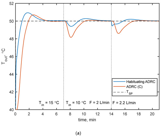
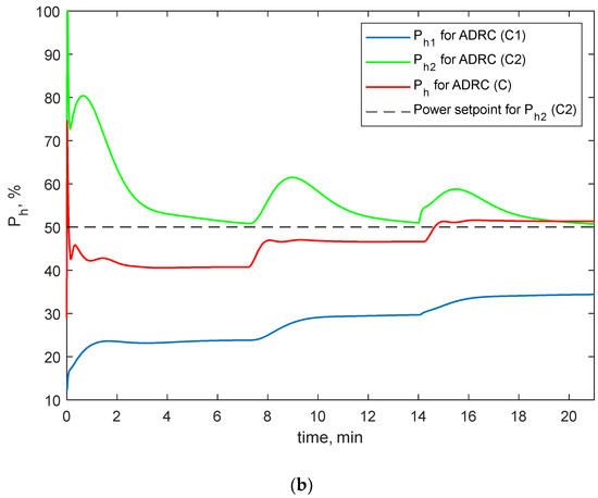
Figure 7.
Validation results of the performance of the proposed ADRC-based HCS operated in the habituating control structure in comparison with the traditional ADRC-based single closed loop control structure shown in Figure 1. Diagram (a) shows the regulated temperature Tout, and diagram (b) shows the corresponding variations of manipulated variables for each case.
The performance of this control structure was also compared with the performance of the traditional HS with a single heater ((7)–(9)) operated in a single closed loop control structure, shown in Figure 1, with a single ADRC controller implemented as the controller C. These results were also obtained by virtual commissioning during the experiment of the same scenario. A single ADRC controller (C) was implemented using the same ADRC function block and was tuned as b0 = 0.002, ωo = 0.104, and ωc = 0.096.
Both experiments started at the same steady state defined by Tin0 = 15 (°C), F0 = 2 (L/min) and Tout0 = 40 (°C). The results showed that, in some terms, one can note the superiority of the proposed double-heater modification of the HS regulated by the dedicated proposed HCS. In general, this configuration ensured better tracking and disturbance rejection. Tracking was much faster, with only a slightly higher overregulation, while disturbance rejection took place significantly smaller under regulation but at the price of a longer settling time. Variations of manipulated variables clearly showed the reason for these differences. HU2 in the habituating control structure was operated much faster by C2; thus, it took the most action responsible for fast tracking and disturbance rejection. HU1 was operated slower by C1, and it adjusted a new operating point of HS. In general, it helped to ensure a better performance, but it is also resulted in a negative impact for longer settling times for Tin and F rejection responses.
These observations are also confirmed quantitatively in Table 1, which shows an assessment of the results presented in Figure 7. This table presents the values of the performance indices MaxOS (maximum over- or undershoot), ST (settling time), IAE (integral absolute error), and energy performance measure Pe,total (energy error) proposed in (Klopot et al., 2021) for the evaluation of the HS performance calculated as:

Table 1.
Control performance indices for the quantitative comparison of the results presented in Figure 7.
All indices were calculated separately for each disturbing response. Their values confirm that, in some terms, the proposed ADRC-based habituating control structure of HCS outperforms a single loop ADRC-based structure. For Tin and F rejection responses, the respective values of MaxOS were significantly smaller for the proposed habituating HCS but with significantly longer ST. The values of MaxOS and ST were comparable for both control structures for the Tsp rejection response. The proposed ADRC-based habituating control structure performed with slightly higher MaxOS but with slightly shorter ST. However, these differences are not very significant in comparison with the much better performance of the proposed habituating HCS structure for each disturbance, measured by both IAE and Pe,total.
Figure 8 shows the results of the same experiment that are presented in Figure 7, but to make the results more realistic, a measurement noise with a variance of 0.05 was added to all measured signals. In general, previous observations were confirmed, but this time, readers should note that, for noise case, the variations of both manipulated variables Ph1 and Ph2 were clearly smoother compared to the variations of Ph corresponding to a single ADRC controller implemented as controller C. Measurement noise slightly influenced the values of the indices presented in Table 1 for the noiseless case, but from a practical viewpoint, the differences were negligible so they were not presented in the paper.
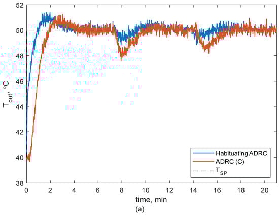
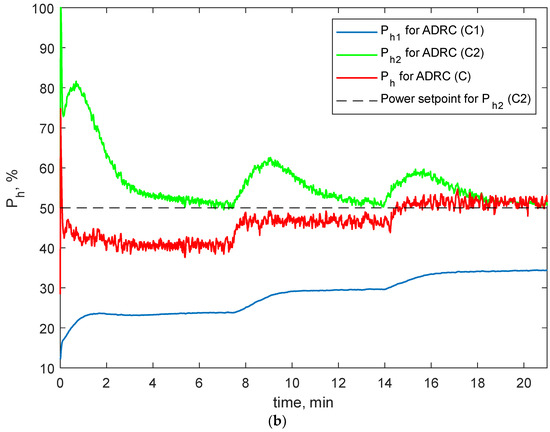
Figure 8.
Results of the experiment shown in Figure 7 with additional measurement noise added to each measured signal. Diagram (a) shows the regulated temperature Tout, and diagram (b) shows the corresponding variations of manipulated variables for each case.
A final validation presented in Figure 9 shows the robustness of both considered HCS structures to the variations of HS dynamics resulting from its operation with different flow rates F. These results were obtained without any retuning of any of the controllers in relation to previous cases. The experiments were carried out for both HCS structures, and each of them was excited by two step changes of Tsp. Each excitation was applied for three different flow rates F. Note that, for the proposed dedicated HCS structure, in the considered range, the value of the flow rate F had no significant influence on the performance. There was a slight difference in overshooting, but the settling time was fully comparable, and these differences are not important from a practical viewpoint. This situation differs significantly from the case when a single ADRC controller operates as the HCS. Then, one can see very significant differences both in overshooting and in settling time. Additionally, for F = 1.5, the closed loop behavior became oscillatory, which shows the potential danger of loss of stability for lower flow rates.
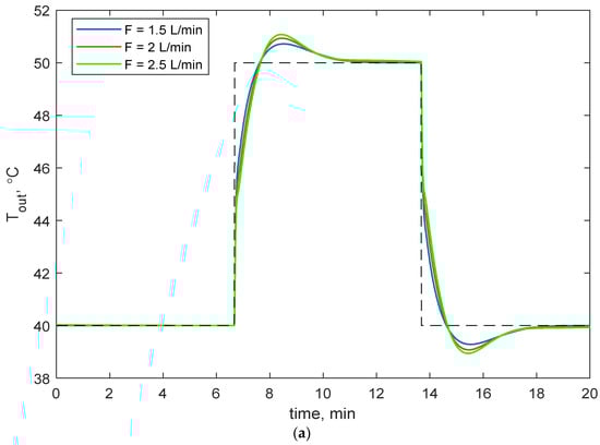
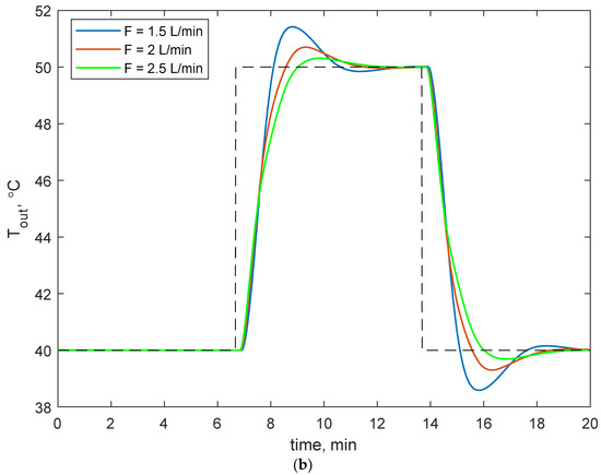
Figure 9.
The robustness of both considered HCS structures. Both figures show the tracking performance of the proposed habituating HCS (a) and a single ADRC structure (b), for different flow rates F.
5. Conclusions
In this paper, how to improve the performance of a traditional single-heater heat source by its modification into a double-heater structure was proposed. Then, for such a modified HS, a dedicated ADRC-based habituating control system was proposed and validated in comparison with the traditional single closed loop control. The results obtained by virtual commissioning show the superiority of the proposed solution in some terms, which makes it an interesting practical alternative for traditional solutions. Implementation of the ADRC-based control system was prepared in the industrial software SIEMENS® PLCSIM Advanced based on the ADRC library general purpose function blocks. The validation includes the influence of the measurement noise and robustness analysis.
In comparison with the traditional approach, the proposed solution requires modification of both the HS and its HCS. Only one modification without the other is pointless, and the application of both results in significant benefits in terms of HS performance. However, HS modification especially must be made carefully. Adding the additional heater HU2 can change the pressure distribution in HS and can consequently limit the maximum achievable flow rate F. Thus, it can also limit the final efficiency of the heat transferring between the HS and HR. In some cases, significant transportation delays can be observed in the dynamics of HS. Then one should consider the application of modified ADRC controllers proposed for applications in the systems with significant dead time [28,29].
Apart from potential problems mentioned above, the proposed modification open new possibilities in further improvement in efficiency and overall performance of HS. The proposed structure of the HCS requires a more systematic approach to the tuning of both controllers. At this moment, a practical tuning procedure was proposed in this paper, but more deterministic tuning rules would be expected. After a detailed analysis of this habituating structure, it can be seen that C1 adjusts the operating point for the whole HS, but it operates every time when C2 changes the value of Ph2. This action could be limited when C2 operates close to its operating point, defined as Ph2,sp. For small changes of Ph2 around Ph2,sp, C1 should not change the value of Ph1. Only significant changes of the operating point should result in such an action. However, it is very difficult to distinguish between long lasting and significant changes of the operating point and the influence of fluctuations of disturbances that can be successfully rejected by C2. This problem requires deeper analysis and potentially could be solved using machine learning. Finally, the application of feedforward for C2 could make it more resistant to variations of H1 (here, feedforward from the temperature at the outlet of H1 could be effective).
The proposed approach can be extended to other industrial sources. Natural extension is the application to a source of cold. A double pump system could also be controlled by the proposed habituating structure.
Author Contributions
Conceptualization, P.N.; investigation, M.F. and P.G.; methodology, P.N., M.F. and P.G.; supervision, J.C.; writing—original draft, J.C. All authors have read and agreed to the published version of the manuscript.
Funding
This work was financed in part by the grant from SUT—subsidy for maintaining and developing the research potential in 2022 (P.G., J.C.), by the BKM grant (BKM 02/060/BKM22/0039) (P.N., M.F.) and co-financed by the European Union through the European Social Fund (grant POWR.03.02.00-00-I029) (P.G.). Calculations were conducted with the use of GeCONiI infrastructure (POIG 02.03.01-24-099).
Institutional Review Board Statement
Not applicable.
Informed Consent Statement
Not applicable.
Data Availability Statement
Not applicable.
Conflicts of Interest
The authors declare no conflict of interest.
References
- Oravec, J.; Bakošová, M.; Galčiková, L.; Slávik, M.; Horváthová, M.; Mészáros, A. Soft-constrained robust model predictive control of a plate heat exchanger: Experimental analysis. Energy 2019, 180, 303–314. [Google Scholar] [CrossRef]
- Stebel, K.; Fratczak, M.; Grelewicz, P.; Czeczot, J.; Klopot, T. Adaptive predictive controller for energy-efficient batch heating process. Appl. Therm. Eng. 2021, 192, 116954. [Google Scholar] [CrossRef]
- Czeczot, J. Modelling for the effective control of the electric flow heaters—Simulation validation. Simul. Model. Pract. Theory 2008, 16, 429–444. [Google Scholar] [CrossRef]
- Klopot, T.; Skupin, P.; Grelewicz, P.; Czeczot, J. Practical PLC-based implementation of adaptive dynamic matrix controller for energy-efficient control of heat sources. IEEE Trans. Ind. Electron. 2021, 68, 4269–4278. [Google Scholar] [CrossRef]
- Gao, Z.; Huang, Y.; Han, J. An alternative paradigm for control system design. In Proceedings of the 40th IEEE Conference on Decision and Control, Orlando, FL, USA, 4–7 December 2001; Volume 5, pp. 4578–4585. [Google Scholar]
- Han, J. From PID to active disturbance rejection control. IEEE Trans. Ind. Electron. 2009, 56, 900–906. [Google Scholar] [CrossRef]
- Gao, Z. Scaling and bandwidth-parameterization based controller tuning. In Proceedings of the American Control Conference, Denver, CO, USA, 4–6 June 2003; pp. 4989–4996. [Google Scholar]
- Gao, Z. Active disturbance rejection control: A paradigm shift in feedback control system design. In Proceedings of the American Control Conference, Minneapolis, MN, USA, 14–16 June 2006; pp. 2399–2405. [Google Scholar]
- Madoński, R.; Herman, P. Survey on methods of increasing the efficiency of extended state disturbance observers. ISA Trans. 2015, 56, 18–27. [Google Scholar] [CrossRef]
- Łakomy, K.; Giernacki, W.; Michalski, J.; Madoński, R. Active disturbance rejection control (ADRC) toolbox for MATLAB/Simulink. arXiv 2022. [Google Scholar] [CrossRef]
- Modonski, R.; Shao, S.; Zhang, H.; Gao, Z.; Yang, J.; Li, S. General error-based active disturbance rejection control for swift industrial applications. Control Eng. Pract. 2019, 84, 218–229. [Google Scholar] [CrossRef]
- Herbst, G. Practical Active Disturbance Rejection Control: Bumpless Transfer, Rate Limitation, and Incremental Algorithm. IEEE Trans. Ind. Electron. 2016, 63, 1754–1762. [Google Scholar] [CrossRef] [Green Version]
- Nowak, P.; Stebel, K.; Klopot, T.; Czeczot, J.; Fratczak, M.; Laszczyk, P. Flexible function block for industrial applications of active disturbance rejection controller. Arch. Control. Sci. 2018, 28, 379–400. [Google Scholar]
- Shi, G.; Wu, Z.; Guo, J.; Li, D.; Ding, Y. Superheated steam temperature control based on a hybrid active disturbance rejection control. Energies 2020, 13, 1757. [Google Scholar] [CrossRef] [Green Version]
- Zwierzewicz, Z.; Dorobczyński, L.; Artyszuk, J. Design and assessment of ADRC-based autopilot for energy-efficient ship steering. Energies 2021, 14, 7937. [Google Scholar] [CrossRef]
- Henson, M.A.; Ogunnaike, B.A.; Schwaber, J. Habituating control strategies for process control. AIChE J. 1995, 41, 604–618. [Google Scholar] [CrossRef]
- Wang, Q.-G.; Zhang, Y.; Cai, W.-J.; Bi, Q.; Hang, C.-C. Co-operative control of multi-input single output processes: On-line strategy for releasing input saturation. Control Eng. Pract. 2001, 9, 491–500. [Google Scholar] [CrossRef]
- Giovanini, L. Cooperative-feedback control. ISA Trans. 2007, 46, 289–302. [Google Scholar] [CrossRef] [PubMed]
- McLain, R.B.; Kurtz, M.J.; Henson, M.A.; Doyle, F.J., III. Habituating control for nonsquare nonlinear processes. Ind. Eng. Chem. Res. 1996, 35, 4067–4077. [Google Scholar] [CrossRef]
- Alvarez-Ramirez, J.; Velasco, A.; Fernandez-Anaya, G. QA note on the stability of habituating process control. J. Process Control 2004, 14, 939–945. [Google Scholar] [CrossRef]
- Herbst, G. A simulative study on Active Disturbance Rejection Control (ADRC) as a control tool for practitioners. Electronics 2013, 2, 246–279. [Google Scholar] [CrossRef]
- Alszer, S.; Krystek, J.; Bysko, S. Simulation and virtual commissioning for intelligent buffer control system–Case study. In Proceedings of the 2nd International Conference on Robotics and Automation Engineering (ICRAE), Shanghai, China, 29–31 December 2017; pp. 207–211. [Google Scholar]
- Lechler, T.; Fisher, E.; Metzner, M.; Mayr, A.; Franke, J. Virtual commissioning—Scientific review and exploratory use cases in advanced production systems. Procedia CIRP 2019, 81, 1125–1130. [Google Scholar] [CrossRef]
- Lee, C.G.; Park, S.C. Survey on the virtual commissioning of manufacturing systems. J. Comput. Des. Eng. 2014, 1, 213–222. [Google Scholar] [CrossRef] [Green Version]
- Fratczak, M.; Nowak, P.; Klopot, T.; Czeczot, J.; Bysko, S.; Opilski, B. Virtual commissioning for the control of the continuous industrial processes—Case study. In Proceedings of the 20th International Conference on Methods and Models in Automation and Robotics (MMAR), Miedzyzdroje, Poland, 24–27 August 2015; pp. 1032–1037. [Google Scholar]
- Grelewicz, P.; Nowak, P.; Fratczak, M.; Klopot, T. Practical verification of the advanced control algorithms based on the virtual commissioning methodology—A case study. In Proceedings of the 23rd International Conference on Methods and Models in Automation and Robotics (MMAR), Miedzyzdroje, Poland, 27–30 August 2018; pp. 217–222. [Google Scholar]
- Fratczak, M.; Nowak, P.; Laszczyk, P. Dynamical aspects of multi-input single-output control for heat distribution processes: Case study. In Proceedings of the 22nd International Conference on Methods and Models in Automation and Robotics (MMAR), Miedzyzdroje, Poland, 28–31 August 2017; pp. 301–306. [Google Scholar]
- Zhao, S.; Gao, Z. Modified active disturbance rejection control for time-delay systems. ISA Trans. 2014, 53, 882–888. [Google Scholar] [CrossRef] [PubMed] [Green Version]
- Zheng, Q.; Gao, Z. Predictive active disturbance rejection control for processes with time delay. ISA Trans. 2014, 53, 873–881. [Google Scholar] [CrossRef] [PubMed]
Publisher’s Note: MDPI stays neutral with regard to jurisdictional claims in published maps and institutional affiliations. |
© 2022 by the authors. Licensee MDPI, Basel, Switzerland. This article is an open access article distributed under the terms and conditions of the Creative Commons Attribution (CC BY) license (https://creativecommons.org/licenses/by/4.0/).