Article

A Load-Independent Self-Oscillating Control of Domino Wireless Power Transfer Systems for High-Voltage Power Grid Monitoring Equipment

Department of Electrical Engineering, The Hong Kong Polytechnic University, Hong Kong 999077, China
*
Author to whom correspondence should be addressed.
Energies 2022, 15(12), 4228; https://doi.org/10.3390/en15124228
Submission received: 4 May 2022 / Revised: 4 June 2022 / Accepted: 7 June 2022 / Published: 8 June 2022
(This article belongs to the Special Issue Future Smart Grids with High Integrations of New Technologies)

Abstract

:
Real-time monitoring devices are popularly utilized in modern power grids. To ensure long-term operations of the monitoring systems under complex outdoor conditions, a reliable and stable power supply is essential. In this paper, a general analysis of domino wireless power transfer (WPT) systems with load-independent outputs is proposed to realize a constant power supply for the monitoring equipment. In addition, the methodology of analyzing the self-oscillating points of the proposed domino WPT systems is deduced. The availability and feasibility of the proposed analysis and control method are verified by both simulation and experiment results based on a four-coil WPT system.

1. Introduction

Online monitoring devices are widely adopted for high-voltage transmission lines (HVTLs) to ensure safe operations, since the electric parameters, wire temperatures, weather conditions, and lifetime detections of the auxiliary equipment for HVTLs are monitored by those devices [1,2,3]. To ensure sustainable operations of the monitoring systems under rainy and snowy weather, reliable power supplies are crucial. Renewable energy sources, such as solar and wind power with energy storage systems, are utilized to supply power. However, the weather-dependent characteristics (e.g., solar energy is unavailable at night) and the massive volume of the equipment have significantly constrained the application value. To solve this issue, the current transformer (CT) mounted on the transmission line is selected to harvest the energy [4,5,6]. The CT can be connected directly to a monitoring device with the same potential as HVTL. However, this method cannot currently be used to power the low-voltage-side monitoring equipment due to insulation requirements. To this end, magnetic coupling wireless power transfer (WPT) is one of the promising technologies to be used [7,8,9,10]. It can provide an appropriate creepage distance and excellent isolation performance. In addition, the cost, volume, and operational complexity of the charging system can be significantly reduced.
The concept of the magnetically coupled resonator, which forms as the transmitter and receiver-side coils compensated with a series of capacitors to transport power wirelessly, was first proposed by Nikola Tesla a century ago [11,12]. Based on the energy transfer mechanisms, WPT can be realized in radiative and non-radiative ways. Radiative WPT is selected as an excellent way to transfer information over a long distance through an antenna in the form of an electromagnetic wave. However, due to the omnidirectional radiation, the energy transfer efficiency is quite low. Alternatively, non-radiative WPT relies on the near-field magnetic coupling of the resonator, which can be classified as short-range, mid-range, and long-range applications. The classification is based on the ratio of the power transfer distance d to the coil radius r [13]. The short-range system is defined as d/r less than 3 [14]. Otherwise, the system is regarded as mid-range or long-range.
Conventionally, the two-stage WPT system is used for the high-voltage power grid monitoring equipment. The two side coils are symmetrically installed on the ends of the high-voltage suspension insulator string. The CT is mounted on the transmission line to harvest the energy through the magnetic field, and the variable-controlled power converter, which generally consists of a rectifier, a dc/dc converter, and a high-frequency dc/ac inverter, is used to realize a high-frequency current flow to the resonators. Then, the energy is transmitted from the transmitter coil to the receiver coil through electromagnetic induction. To facilitate the analysis, the CT with the converter is regarded as a DC voltage source with a dc/ac inverter in the following session. For the traditional two-stage WPT systems, the power transfer efficiency is greatly limited by the transmission distance between the two side coils. To improve the power transfer distance, the coil sizes are required to be designed as enormous to enhance the mutual inductance between the two inductors. However, it could be difficult for the coil installation. Alternatively, domino WPT systems are put forward to be used to reduce the coil size while still maintaining a high transfer efficiency. The intermediate coils as domino structures have been widely adopted between the transmitter and receiver coil in the recent decade [15,16,17,18]. The block diagram of the traditional two-stage and domino WPT system for high-voltage power grid monitoring equipment is depicted as shown in Figure 1. The relay coils can enhance the magnetic field between its adjacent units and make robust the coupled regime. In [19], the research team achieved the transfer of 60 watts with 40% efficiency over distances of two meters by using the relay coils located nearby the transmitter and receiver loop, and in [20], the domino WPT system with seven relay coils can achieve 70% efficiency at the transfer distance of 0.7 m. It is noticed that the characteristics of the domino-resonator are not only to improve the power transfer capability over a long distance but also to achieve load-independent output regulation [21,22,23]. Therefore, it is beneficial to provide an efficient and stable charging process for the monitoring devices.
As one of the emerging applications, using the domino WPT systems for power supply to the monitoring equipment on the HVTLs is developing rapidly. In [24], an optimization method is proposed to improve the quality factor and coupling effect of domino WPT systems, and 16.7 W output power with 15% efficiency is realized over a 1.5 m transmission distance. In addition, the magnetic field distribution of insulator strings in the HVTL system is simulated. The results show that the cross-coupling effect between the HVTL and the domino WPT system can be ignored, which significantly reduces the complexity of the system modeling. In [25], the rotating multi-coil receiver structure has been adopted for the domino WPT system by realizing a 20 W power system with a transmission distance above 1.12 m. In [26], the transmission distance of the WPT system is proved to be enhanced by increasing the system operating frequency higher than the resonant frequency, and [27] realized a high transfer distance under a 600 kHz operating frequency. In reference [28], the compensation structure of the receiver-side circuit is changed to ensure a stable output, while still maintaining an appropriate transmission distance.
However, using the WPT systems to supply the power to the monitoring device also has some limitations: First, the power of the WPT system depends on the gird system. If the current in the HVTL is too low, the WPT system may not have enough power to ensure the normal operation of the monitoring device. Second, when the power supply system has an open circuit fault, the WPT system will be out of work. Third, the WPT system operating performance would be influenced by the outdoor environment, such as the coils would be distorted on rainy or snowy days.

2. Review of Output Control Methods and Self-Oscillating Control Schemes

Output regulation is one of the most critical factors in guaranteeing stable load charging requirements. A great deal of research has been devoted to regulating the system output. Generally, an output power controller, such as a dc/dc converter, is installed on the receiver side to control the system output performance [29,30,31]. However, the high cost of the auxiliary device and control complexity is non-negligible. In [32], the voltage differential signal of the primary side circuit is used to track the working frequency automatically. However, it is only suitable for parallel-series (PS) compensation schemes. In [33], sub-resonant frequency control is proposed to realize a constant current (CC) output by adjusting the system operating frequency. However, the CC control reliability is limited by a specific range of variation for the mutual inductance. In [34], pulse width modulation (PWM) with a phase lock loop (PLL) control strategy is proposed. Although it can achieve output voltage regulation well, the two coupled control loops complicate the realization.
To overcome the above issues, the self-oscillating control strategy has been well investigated in [35,36,37,38]. The researchers have funded an interesting phenomenon, in that the fundamental component of the receiver-side current is always in-phase or reverse-phase with the system input voltage under the load-independent output voltage mode in the two-stage S-S compensated WPT systems [36]. This is because the equivalent impedance associated with load resistance is a pure imaginary part when the system equivalent series resistances (ESRs) are ignored. This indicates the system will automatically operate at the load-independent CV mode by synchronizing the switching signals of the inverter to be consistent with the zero-crossing compensation signal of the receiver current, as the imaginary part of the equivalent impedance will be zero. One of the outstanding merits of the self-oscillating control strategy is for more straightforward implementation, as only the phase detection of the receiver-side current is needed. In addition, it can achieve better dynamic performance under varying load conditions and self-adaptability with the parameter deviations, especially for the domino WPT systems, as the parameters of the system elements, e.g., inductors and capacitors, are more sophisticated than the traditional two-coil systems. The self-oscillating control diagram for the proposed domino WPT systems is shown in Figure 2. A current sensor is installed on the receiver-side circuit to detect the current. The detected current is then transmitted to a zero-compensation block (e.g., operational amplifier), where the sine-wave signal will turn into the square-wave signal. The square-wave signal will transfer from the receiver side to the transmitter side through wireless communication. The initial driving signals (e.g., square wave drive signals) are employed for the inverter to start the oscillating. Then, the switching signal will be shifted to the self-oscillating control signal to ensure the system can provide a constant voltage output to the monitoring equipment. However, the above-mentioned control schemes are generally utilized for the two-coil WPT systems, and the performance of the domino WPT system is rarely discussed.

3. System Modeling and Analysis Method

3.1. System Description of Three-Coil WPT Systems

To facilitate the analysis, a three-coil WPT system was built first. The topology of the system, which comprises an AC power source (i.e., vt), three-coupled resonators, and a load (i.e., RL), is depicted as shown in Figure 3. The domino-resonator is composed of compensated capacitors, three-coupled coils, and equivalent series resistances (ESRs) that are defined as C1, C2, and C3; L1, L2, and L3; R1, R2, and R3, respectively. The mutual inductances of each adjacent coil are defined as M1 and M2. The currents on each unit are defined as it, i2, and ir. ω is the system operating angular frequency. In addition, the effects of unwanted cross-coupling between the non-adjacent coil can be eliminated through the specified coil design or suitable distance [39]. Based on the schematic diagram in Figure 3, a T-type equivalent circuit is built, as shown in Figure 4.
According to the T-type model, the equivalent impedance can be defined as:
Z 1 = j ( ω L 1 1 ω C 1 + ω M 1 ) + R 1
Z 2 = j ( ω L 2 1 ω C 2 + ω M 1 + ω M 2 ) + R 2
Z 3 = j ( ω L 3 1 ω C 3 + ω M 2 ) + R 3
Z m 1 = j ω M 1
Z m 2 = j ω M 2

3.2. Load-Independent Voltage Gain Characteristics

To analyze the load-independent voltage output characteristics for the proposed three-coil WPT system, the relationship between the system input voltage and the system output voltage needs to be figured out. Applying Kirchhoff Voltage Law (KVL) and Kirchhoff Current Law (KCL) on the circuit in Figure 4, we obtain:
v t = i t Z 1 + i 2 Z 2 + i r ( Z 3 + R L )
i m 1 = i 2 Z 2 + i r ( Z 3 + R L ) Z m 1
i m 2 = i r ( Z 3 + R L ) Z m 2
i t = i m 1 + i 2
i 2 = i m 2 + i r
v r = i r R L
Based on (2a)–(2f), the relationship between vt and vr can be defined as:
v t = ( A R L + B ) v r
where
A = [ ( Z 3 + Z m 2 ) [ Z 2 Z 1 + ( Z 2 + Z 1 ) Z m 1 ] + Z 3 Z m 2 ( Z m 1 + Z 1 ) ] Z m 1 Z m 2
B = [ Z 2 Z 1 + ( Z 2 + Z 1 ) Z m 1 + Z m 2 ( Z m 1 + Z 1 ) ] Z m 1 Z m 2
Based on (3), the load-independent voltage output can be achieved by controlling the operating frequency to satisfy:
( Z 3 + Z m 2 ) [ Z 2 Z 1 + ( Z 2 + Z 1 ) Z m 1 ] + Z 3 Z m 2 ( Z m 1 + Z 1 ) = 0  
Combining with (1), (4) can be expanded as:
j ( ω L 3 1 ω C 3 ) ( ω 2 L 1 L 2 + L 2 + M 2 C 1 + L 1 C 2 1 ω 2 C 1 C 2 ω 2 L 1 M 2 + ω 2 M 1 2 ) + j ( ω L 1 1 ω C 1 ) ( ω 2 L 3 M 2 M 2 C 3 + ω 2 M 2 2 ) = 0  
In general, the circuit parameters for each relay unit are designed as the same (i.e., L1 = L2 = L3 and C1 = C2 = C3). Therefore, (5) can be further simplified, and the load-independent CV angular frequencies (i.e., ω1, ω2, and ω3) can be expressed as:
ω 1 = 1 L 1 C 1
ω 2 = ω o 2 ( 1 k 1 2 + k 2 2 ) 1 k 1 2 k 2 2
ω 3 = ω o 2 ( 1 + k 1 2 + k 2 2 ) 1 k 1 2 k 2 2
where the system resonant angular frequency ωo can be expressed as:
ω o = 1 L 1 C 1 = 1 L 2 C 2 = 1 L 3 C 3
and the coupling coefficient k1 and k2 are shown as:
k 1 = M 1 L 1 L 2
k 2 = M 2 L 2 L 3
The corresponding output-to-input voltage gain Gv can be represented as:
G v = v r v t = | Z m 1 Z m 2 [ Z 2 Z 1 + ( Z 2 + Z 1 ) Z m 1 + Z m 2 ( Z m 1 + Z 1 ) ] |  
It has been proved that the system input voltage is in-phase or reverse-phase with the receiver-side current at the load-independent frequency for the two-coil WPT systems. However, the above phenomenon for the domino WPT systems is not clear. To facilitate the analysis, (3) can be re-represented as:
v t = ( A + B R L ) i r
Since A is an imaginary number and B is a real number, vt is in-phase with ir when A = 0 and B > 0, and vt is reverse-phase with ir when A = 0 and B < 0. In addition, A = 0 is the solution for the load-independent frequencies deduced in (4). Therefore, the inverter can be automatically operated at the load-independent frequencies by synchronizing the switching signals of the inverter to be consistent with the zero-crossing compensation signal of the receiver current. To realize the self-oscillating control scheme, the phase detection of the receiver-side current is needed, and the required information can be transmitted from the receiver-side circuit to the transmitter side circuit through wireless communication.

3.3. Load-Independent Frequency Prediction for N-Coil WPT Systems

From the analysis mentioned above, the load-independent characteristics for three-coil domino WPT systems are analyzed. Next, the topology is extended to N-coupled resonators (i.e., N = n + 1). A T-type equivalent circuit of the N-coupled resonators is plotted, as shown in Figure 5.
Here,
Z 1 = j ( ω L 1 1 ω C 1 + ω M 1 ) + R 1
Z n = j ( ω L n 1 ω C n + ω M n 1 + ω M n ) + R n
Z n + 1 = j ( ω L n + 1 1 ω C n + 1 + ω M n ) + R n + 1
Z m n = j ω M n
The limited condition for (9b)–(9c) is n ≥ 2. Similarly, by applying the KVL and KCL on the circuit, the relationship between the vt and vr can be defined as:
v t = ( C R L + D ) v r
where
D = [ f ( A n ) + f ( B n ) ] i = 1 n Z m i
f ( A n ) = ( Z m n 1 + Z n ) f ( A n ) + Z n f ( B n 1 )
f ( B n ) = Z m n [ f ( A n 1 ) + f ( B n 1 ) ]
f ( A 1 ) = Z 1
f ( B 1 ) = Z m 1
and
C = [ f ( C n ) + f ( D n ) ] i = 1 n Z m i
f ( C n ) = ( Z m n + Z n + 1 ) f ( A n )
f ( D n ) = Z n + 1 f ( B n )
f(∙) is a function to describe the relationship between the impedance. Based on (10), the load-independent voltage output for domino WPT systems can be deduced by satisfying:
f ( C n ) + f ( D n ) = 0  
In this way, the system output-to-input voltage gain Gv is only dependent on the system parameters in the expression 1/D regardless of the variation in load conditions. Hence, the load-independent operating frequencies for the N-coil WPT systems can be acquired.

4. Simulation Verification

To verify the effectiveness of the theoretical analysis, a four-coil S-S compensated WPT system was built on PSIM. 12. 04. To simplify the analysis, the self-inductance for each coil is set as the same value (i.e., L1 = L2 = ... = L4). Similarly, the corresponding compensated capacitors are the same (i.e., C1 = C2 = ... = C4), and the mutual inductances between different coils are the same (i.e., M1 = M2 = M3). The receiver-side circuit is adopted as a passive load without a rectifier structure. Generally, the quality factors ( Q i = ω L i / R i ) for the coils are high for realizing desirable transfer efficiency. Hence, the ESR for each circuit can be ignored. In addition, to reduce the unwanted cross-coupling effect, the coils are set at a long distance, which is displayed as a relatively low mutual inductance value. The system parameters are designed to ensure the system resonant frequency is nearly 100 kHz, which is one of the typical operating frequencies that has been adopted for inductive-type WPT systems. The system’s main parameters are shown in Table 1.
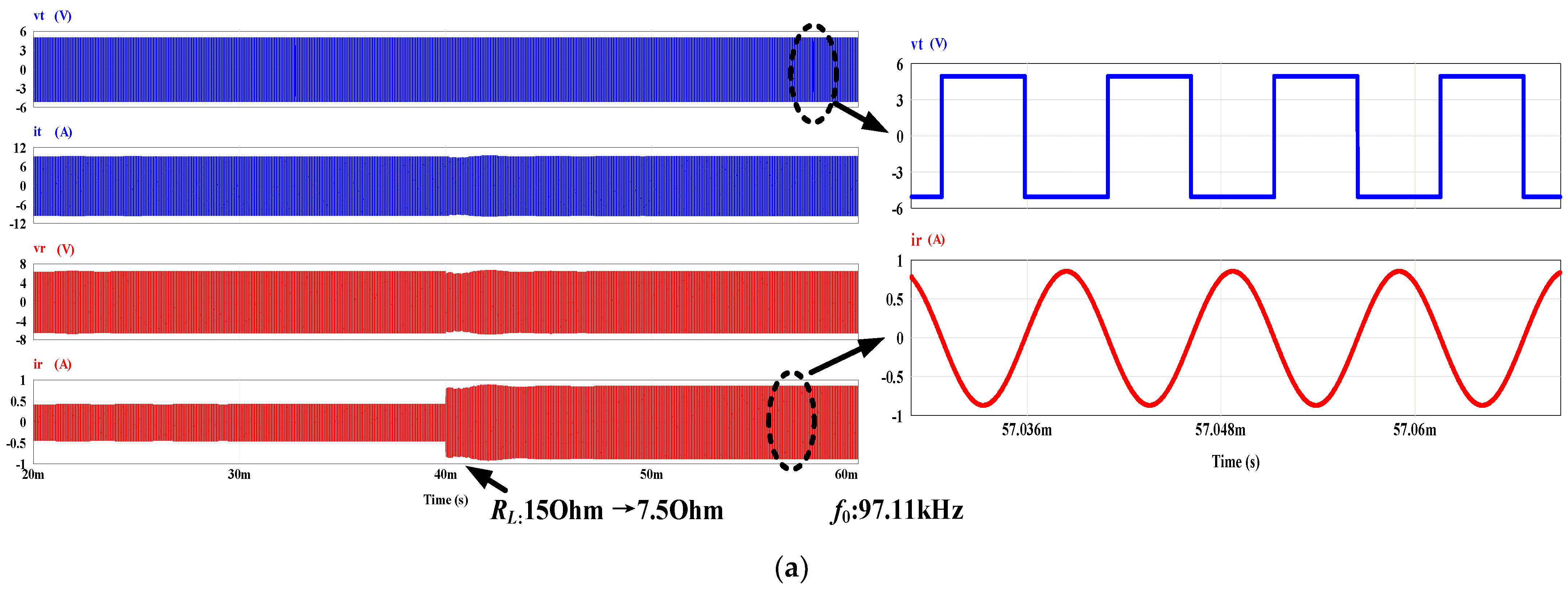
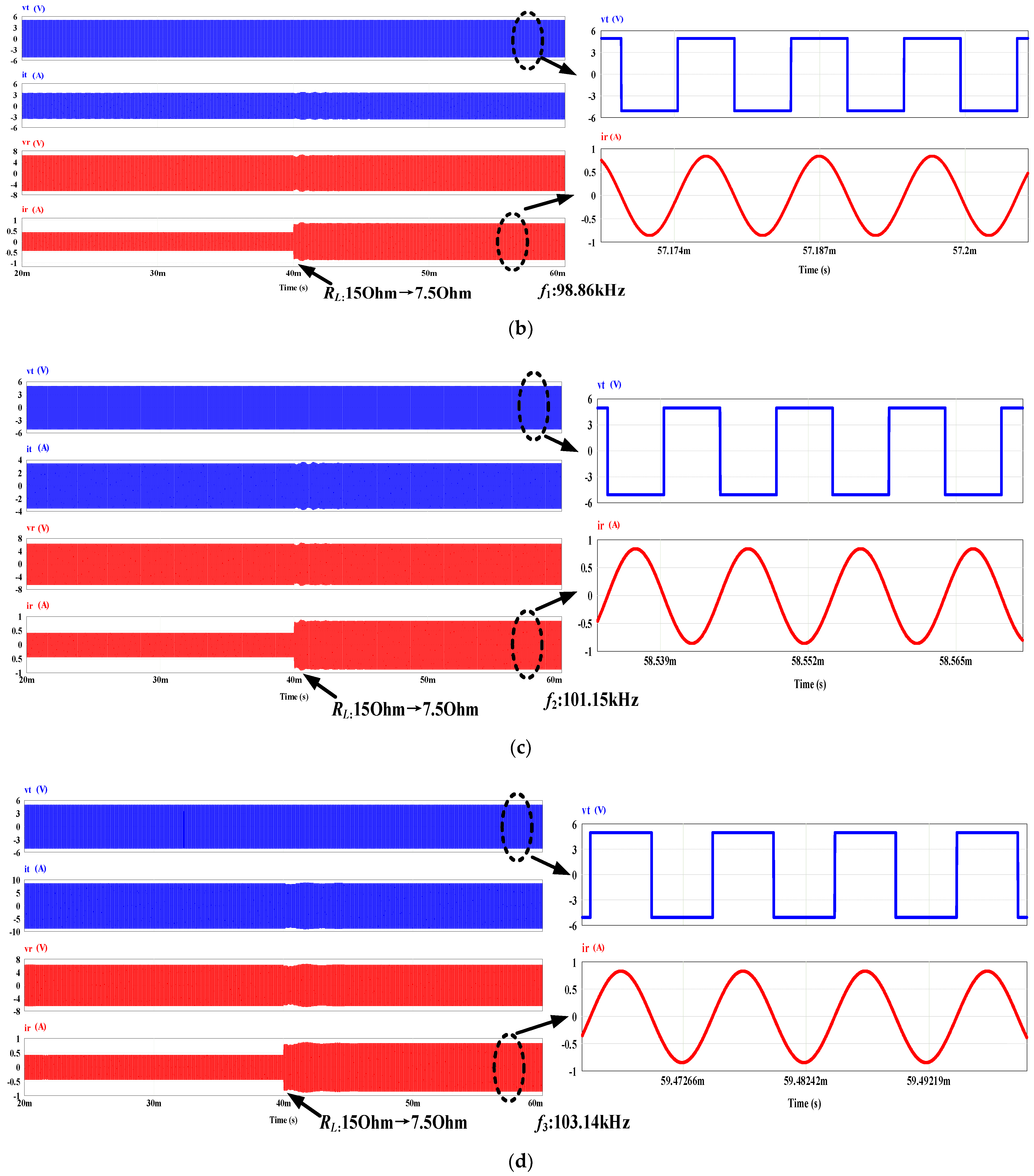
By solving (10), it can be obtained that the system has four load-independent CV output frequencies (i.e., f0 = 97.11 kHz, f1 = 98.86 kHz, f2 = 101.15 kHz, and f3 = 103.14 kHz). To verify the above-mentioned analysis, the load is shifted from 15 Ω to 7.5 Ω and the simulation time is 40 ms. The main waveforms of the input voltage (i.e., vt), input current (i.e., it), output voltage (i.e., vr), and output current (i.e., ir), are shown in Figure 6a–d, respectively.
It can be seen from Figure 6 that the output voltage can maintain constant versus load shift under the above four load-independent frequencies. In contrast, the fluctuation of the output current is significant. The input voltage is in-phase with the output current in f1 and f3, as shown in Figure 6b,d, respectively, while the input voltage is reverse-phase with the output current in f0 and f2, as shown in Figure 6a,c, respectively. It should be noticed that the above simulations are carried out by setting the system operating frequencies to the pre-calculated values.

5. Experimental Verification

5.1. Experimental Setup

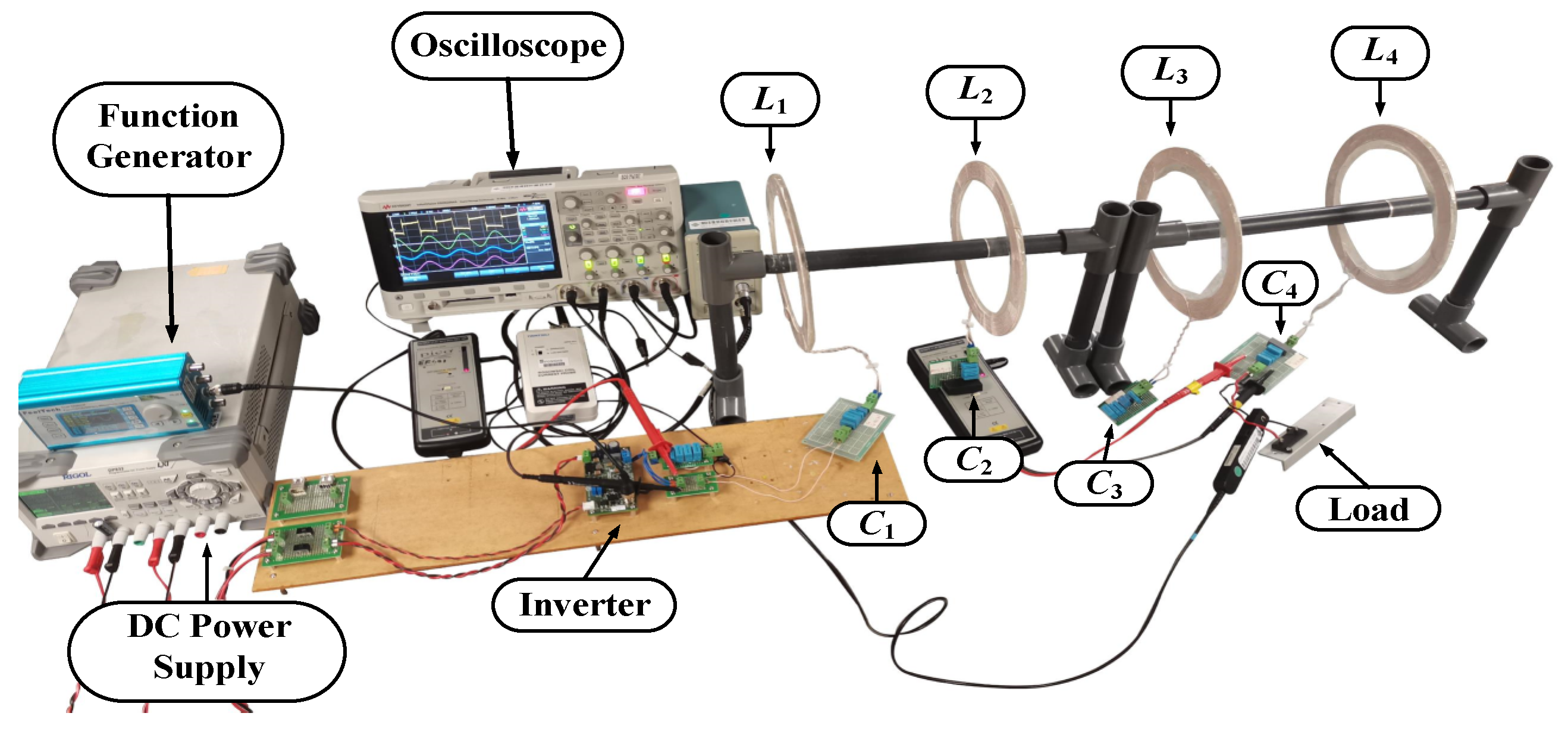
As for the composite pin insulator model (FPQ35-35/5T), the length of the insulator is around 0.61 m. The transmitter coil, receiver coil, and relay coil are embedded into four insulator sheds spaced at near 0.2 m intervals. Therefore, a four-coil domino WPT system with a total transfer distance of around 0.6 m and the interval between each adjacent coil at near 0.2 m is built. Since the power requirements for different types of monitoring devices range from a few tenths of a watt to tens of watts, the low output power scenario is adopted in this experiment. The schematic of the experimental setup is shown in Figure 7, and the photograph of the experimental setup is shown in Figure 8. A DC power source is adapted to supply the power of the system, and the DC voltage is converted to the AC voltage through the full-bridge inverter (GS61004B-EVBCD). The square-wave switching signal is realized by a function generator. The resonators are compensated as series topology. The main waveforms, amplitudes, and the phase angle between the input voltage and output current are captured through the oscilloscope. The main parameters of the system are listed in Table 2.

5.2. Experimental Results

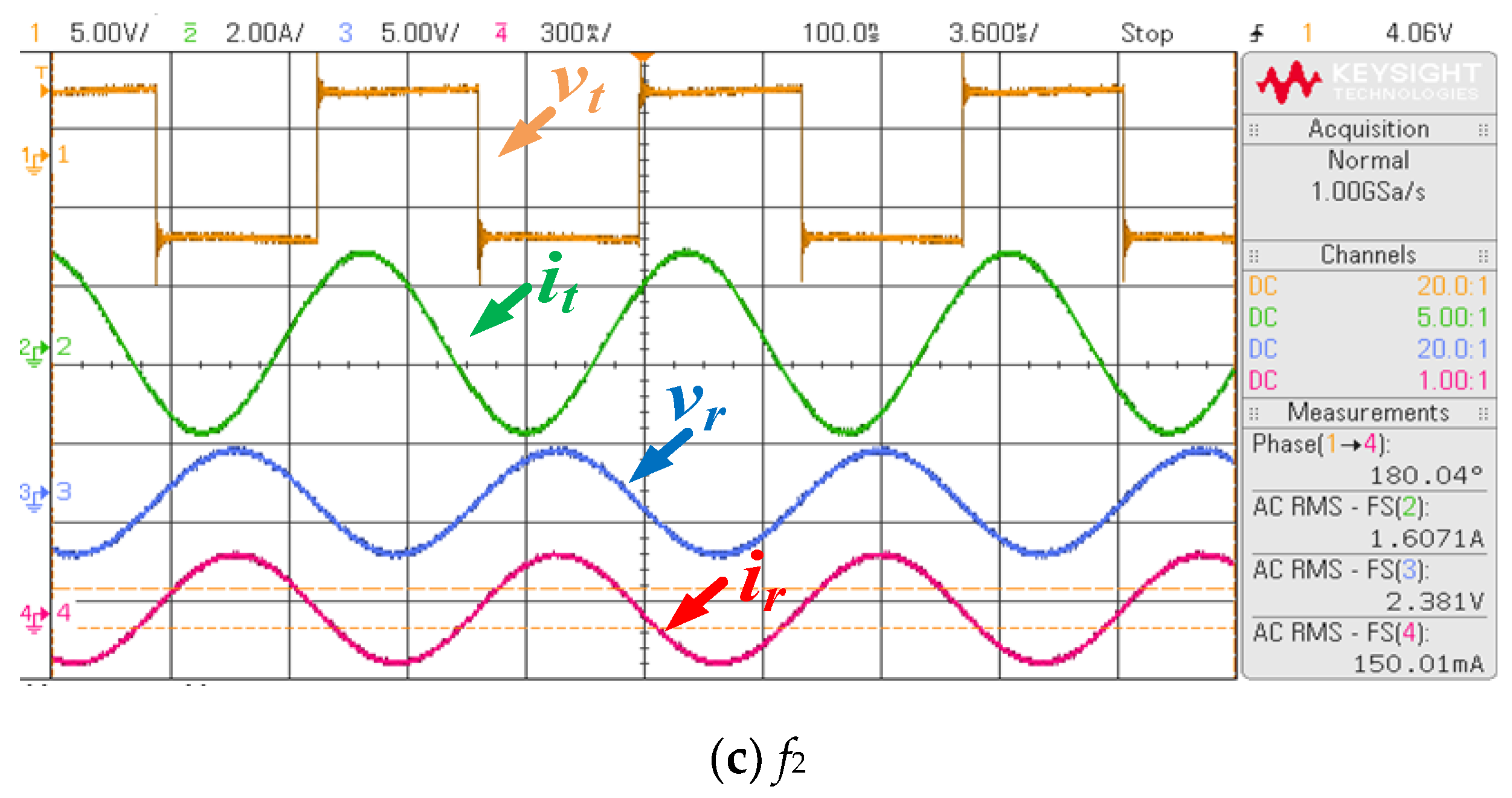
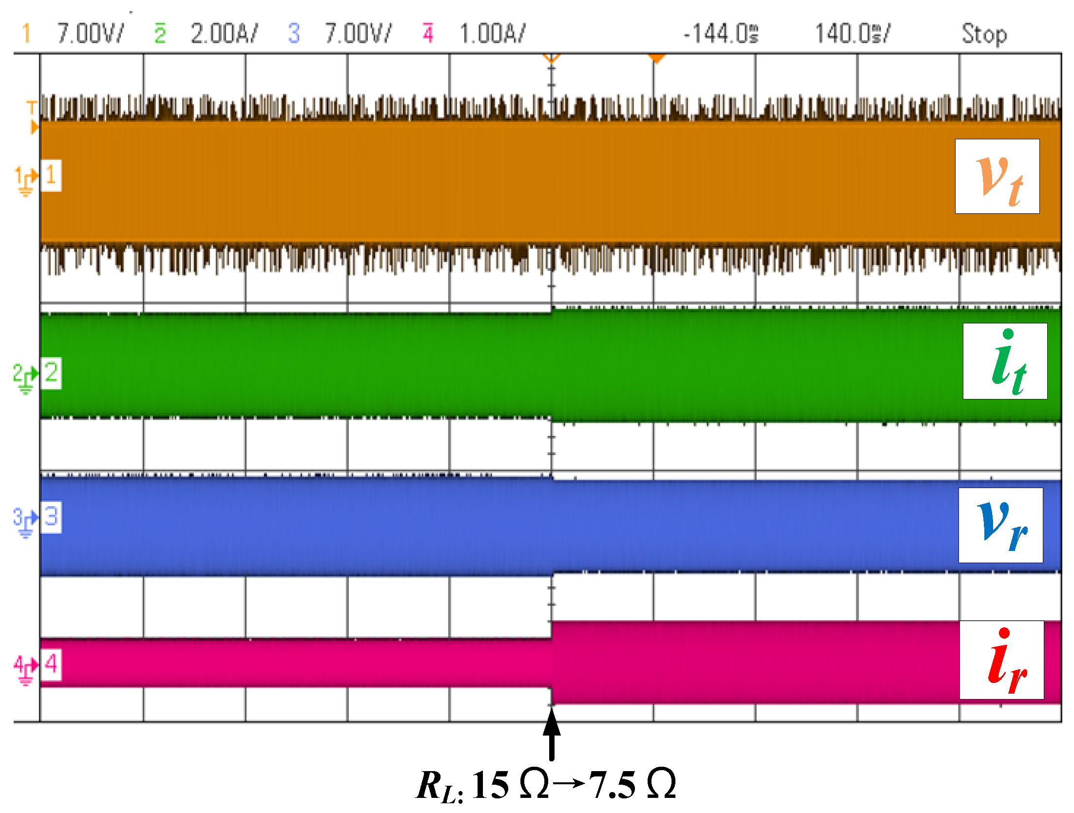
Due to the influence of the unequal parameters and ESRs, three self-oscillating frequencies (i.e., f0, f1, and f2) were observed. The calculated and experimental measured results of the three self-oscillating frequencies and the corresponding voltage gains are shown in Table 3. The errors caused by system parameter deviation are unavoidable in practice. The experimental waveforms of input voltage (i.e., vt), transmitter current (i.e., it), output voltage (i.e., vr), and receiver current (i.e., ir) at the three load-independent frequencies are shown in Figure 9. It can be seen that the input voltage is in-phase with the receiver current at f1, and it is reverse-phase with the receiver current at f0 and f2. The transient waveforms of vt, it, vr, and ir for f1 are depicted as shown in Figure 10. To verify the effectiveness of the load-independent CV output characteristics, the load is switched from 15 Ω to 7.5 Ω under the system operating frequency at f1. The variation in system parameters for the load resistance shifted is shown in Table 4. It has been reported that the system cannot achieve ideal constant CV output due to the existed ESRs in practice [40,41]. In this case, the output voltage varied from 2.83 V to 2.69 V, with deviations of about 4.9%, representing that the system nearly operates at the load-independent CV output mode. In addition, the system efficiency is changed from 15% to 24%. Nevertheless, efficiency is not the main focus of this article because the power level is quite low.

6. Conclusions and Future Discussions

In this paper, the concept of utilizing a domino-resonator as the power supply system for the monitoring devices on the high-voltage transmission lines is introduced. In addition, a general analysis of domino WPT systems with load-independent output features is proposed to realize a constant output voltage supply to the monitoring equipment. A four-coil domino WPT system is established to validate the effectiveness of the proposed method in practice.
Despite the realization of the CV output for domino WPT systems having been reported in many ways, the concept of using the self-oscillating control on the domino WPT systems is rare. In addition, how to implement this control scheme for domino WPT systems with high stability, such as avoiding wireless communication, should be further studied. Furthermore, the cross-coupling effects may not be entirely eliminated in practice. Hence, the influence caused by the unwanted cross-coupling also needs to be considered.

Author Contributions

K.W. is responsible for finishing the methodology, simulation, and experiments in this paper. The experimental coils were produced by R.L. The supervision, review, and editing of the papers were mainly carried out by K.W. and Y.Y. All authors have read and agreed to the published version of the manuscript.

Funding

This research was funded by Guangdong Basic and Applied Basic Research Foundation, grant number 2022A1515010708.

Institutional Review Board Statement

Not applicable.

Informed Consent Statement

Not applicable.

Data Availability Statement

Not applicable.

Conflicts of Interest

The authors declare no conflict of interest.

References

  1. Gouda, O.; Khalifa, D. On-Line Monitoring of High Voltage Transmission Line; Lambert Academic Publishing: Saarbrucken, Germany, 2012. [Google Scholar]
  2. Sun, X.; Huang, Q.; Jiang, L.J.; Pong, P.W.T. Overhead high-voltage transmission-line current monitoring by magnetoresistive sensors and current source reconstruction at transmission tower. IEEE Trans. Magn. 2014, 50, 4000405. [Google Scholar] [CrossRef] [Green Version]
  3. Ting, Y.; Xuanshu, C.; Du, Y.; Yejun, H. Research on power supply employed in ices real-time monitoring system of high-voltage transmission lines. In Proceedings of the International Conference on High Voltage Engineering and Application (ICHVE), Chongqing, China, 9–12 November 2008; pp. 626–628. [Google Scholar]
  4. Du, L.; Wang, C.; Li, X.; Yang, L.; Mi, Y.; Sun, C. A novel power supply of online monitoring systems for power transmission lines. IEEE Trans. Ind. Electron. 2010, 57, 2889–2895. [Google Scholar]
  5. Zhuang, Y.; Xu, C.; Song, C.; Chen, A.; Lee, W.; Huang, Y.; Zhou, J. Improving current transformer-based energy extraction from AC power lines by manipulating magnetic field. IEEE Trans. Ind. Electron. 2020, 67, 9471–9479. [Google Scholar] [CrossRef]
  6. Li, P.; Wen, Y.; Zhang, Z.; Pan, S. A high-efficiency management circuit using multi winding up conversion current transformer for powerline energy harvesting. IEEE Trans. Ind. Electron. 2015, 62, 6327–6335. [Google Scholar] [CrossRef]
  7. Zhang, J.; He, Z.; Liu, Y.; Luo, A.; Wang, L.; Wang, H.; Chen, Y.; Pang, Y. High-efficiency push-pull resonant converter solution for auxiliary power supply in 70-kV isolated applications. IEEE J. Emerg. Sel. Top. Power Electron. 2022, 10, 632–647. [Google Scholar] [CrossRef]
  8. Qu, J.; Lee, C.K. Dynamic modeling for the wireless power transfer system in domino structure. IEEE Trans. Ind. Electron. 2022, 69, 3556–3565. [Google Scholar] [CrossRef]
  9. Fang, Y.; Qu, J.; Pong, B.M.H.; Lee, C.K.; Hui, R.S.Y. Quasi-static modeling and optimization of two-layer PCB resonators in wireless power transfer systems for 110-kV power grid online monitoring equipment. IEEE Trans. Ind. Electron. 2022, 69, 1400–1410. [Google Scholar] [CrossRef]
  10. Wu, N.; Xiao, J.; Han, S.; Zhang, L.; Chen, L. Insulation analysis of high-voltage transmission line insulator with embedded wireless power transfer coils. In Proceedings of the IEEE 2nd China International Youth Conference on Electrical Engineering (CIYCEE), Chengdu, China, 15–17 December 2021; pp. 1–5. [Google Scholar]
  11. Lomas, R. The Man Who Invented the Twentieth Century—Nikola Tesla—Forgotten Genius of Electricity; Headline Book Publishing Ltd.: London, UK, 1999; p. 146. [Google Scholar]
  12. Tesla, N. Apparatus for Transmitting Electrical Energy. U.S. Patent 1,119,732, 1 December 1914. [Google Scholar]
  13. Zhong, W.; Lee, C.K.; Hui, S.Y.R. General analysis on the use of Tesla’s resonators in domino forms for wireless power transfer. IEEE Trans. Ind. Electron. 2013, 60, 261–270. [Google Scholar] [CrossRef] [Green Version]
  14. Choi, B.H.; Thai, V.X.; Lee, E.S.; Kim, J.H.; Rim, C.T. Dipole-Coil-based wide-range inductive power transfer systems for wireless sensors. IEEE Trans. Ind. Electron. 2016, 63, 3158–3167. [Google Scholar] [CrossRef]
  15. Hui, S.Y.R.; Zhong, W.; Lee, C.K. A critical review of recent progress in mid-range wireless power transfer. IEEE Trans. Power Electron. 2014, 29, 4500–4511. [Google Scholar] [CrossRef] [Green Version]
  16. Lee, C.K.; Zhong, W.X.; Hui, S.Y.R. Effects of magnetic coupling of nonadjacent resonators on wireless power domino-resonator systems. IEEE Trans. Power Electron. 2012, 27, 1905–1916. [Google Scholar] [CrossRef] [Green Version]
  17. Zhong, W.X.; Lee, C.K.; Hui, S.Y. Wireless power domino-resonator systems with noncoaxial axes and circular structures. IEEE Trans. Power Electron. 2012, 27, 4750–4762. [Google Scholar] [CrossRef] [Green Version]
  18. Feng, J.; Li, Q.; Lee, F.C. Load detection and power flow control algorithm for an omnidirectional wireless power transfer system. IEEE Trans. Ind. Electron. 2022, 69, 1422–1431. [Google Scholar] [CrossRef]
  19. Kurs, A.; Karalis, A.; Moffatt, R.; Joannopoulos, J.D.; Fisher, P.; Soljačić, M. Wireless power transfer via strongly coupled magnetic resonances. Science 2007, 317, 83–86. [Google Scholar] [CrossRef] [Green Version]
  20. Dong, Z.; Liu, S.; Li, X.; Xu, Z.; Yang, L. A novel long-distance wireless power transfer system with constant current output based on domino-resonator. IEEE J. Emerg. Sel. Top. Power Electron. 2021, 9, 2343–2355. [Google Scholar] [CrossRef]
  21. Cheng, C.; Li, W.; Zhou, Z.; Deng, Z.; Mi, C. A load-independent wireless power transfer system with multiple constant voltage outputs. IEEE Trans. Power Electron. 2020, 35, 3328–3331. [Google Scholar] [CrossRef]
  22. Cheng, C.; Zhou, Z.; Li, W.; Deng, Z.; Mi, C.C. A power relay system with multiple loads using asymmetrical coil design. IEEE Trans. Power Electron. 2021, 68, 1188–1195. [Google Scholar] [CrossRef]
  23. Chen, T.; Cheng, C.; Cheng, H.; Wang, C.; Mi, C.C. A multi-load capacitive power relay system with load-independent constant current outputs. IEEE Trans. Power Electron. 2022, 37, 6144–6155. [Google Scholar] [CrossRef]
  24. Cai, C.; Wang, J.; Liu, R.; Fang, Z.; Zhang, P.; Long, M.; Hu, M.; Lin, Z. Resonant wireless charging system design for 110-kV high-voltage transmission line monitoring equipment. IEEE Trans. Ind. Electron. 2019, 66, 4118–4129. [Google Scholar] [CrossRef]
  25. Huang, X.; Yan, C.; Wang, W.; Zhao, J.; Tan, L. Hybrid wireless charging system for monitoring overhead 110 kV high-voltage power line equipment based on magneto-electric conversion. IET Gener. Transm. Distrib. 2016, 10, 1199–1208. [Google Scholar]
  26. Syms, R.; Shamonina, E.; Kalinin, V.; Solymar, L. A theory of metamaterials based on periodically loaded transmission lines: Interaction between magneto-inductive and electromagnetic waves. J. Appl. Phys. 2005, 97, 064909. [Google Scholar] [CrossRef] [Green Version]
  27. Zhou, H.; Gao, X.; Lai, J.; Hu, W.; Deng, Q.; Zhou, D. Natural frequency optimization of wireless power systems on power transmission lines. IEEE Access 2018, 6, 14038–14047. [Google Scholar] [CrossRef]
  28. Yan, Z.; Xie, H.; Li, Y.; He, Z.; Yang, H.; Zhou, W.; Zhu, C.; Jing, X.; Chen, S.; Mai, R. A Monitoring Equipment Charging System for HVTL Based on Domino-Resonator WPT With Constant Current or Constant Voltage Output. IEEE Trans. Power Electron. 2022, 37, 3668–3680. [Google Scholar] [CrossRef]
  29. Yang, Y.; Zhong, W.; Kiratipongvoot, S.; Tan, S.; Hui, S. Dynamic improvement of series-series compensated wireless power transfer systems using discrete sliding mode control. IEEE Trans. Power Electron. 2018, 33, 6351–6360. [Google Scholar] [CrossRef]
  30. Li, H.; Li, J.; Wang, K.; Chen, W.; Yang, X. A maximum efficiency point tracking control scheme for wireless power transfer systems using magnetic resonant coupling. IEEE Trans. Power Electron. 2015, 30, 3998–4008. [Google Scholar] [CrossRef]
  31. Yang, Y.; Qin, Y.; Tan, S.C.; Hui, S.Y.R. Efficient improvement of photovoltaic-battery systems in standalone DC microgrids using a local hierarchical control for the battery system. IEEE Trans. Power Electron. 2019, 34, 10796–10807. [Google Scholar] [CrossRef]
  32. Yao, Y.; Wang, Y.; Cheng, H.; Lu, K.; Guan, Y.; Gao, S.; Liu, X.; Xu, D. A variable frequency control (VFC)-based WPT system featuring constant voltage output, less power stages, and lower system costs. In Proceedings of the 2019 22nd International Conference on Electrical Machines and Systems (IC2019 22nd International Conference on Electrical Machines and Systems (ICEMS), Harbin, China, 11–14 August 2019; pp. 1–5. [Google Scholar]
  33. Guidi, G.; Suul, J.A. Minimizing converter requirements of inductive power transfer systems with constant voltage load and variable coupling conditions. IEEE Trans. Ind. Electron. 2016, 63, 6835–6844. [Google Scholar] [CrossRef] [Green Version]
  34. Gati, E.; Kampitsis, G.; Stavropoulos, I.; Papathanassiou, S.; Manias, S. Wireless phase-locked loop control for inductive power transfer systems. In Proceedings of the 2015 IEEE Applied Power Electronics Conference and Exposition (APEC), Charlotte, NC, USA, 15–19 March 2015. [Google Scholar]
  35. Wang, X.; Liu, S.; Li, Q.; Xu, H. Self-oscillating control method and topology analysis for parallel resonant contactless power transfer systems. In Proceedings of the 2017 IEEE PELS Workshop on Emerging Technologies: Wireless Power Transfer (WoW), Chongqing, China, 20–22 May 2017. [Google Scholar]
  36. Yan, K.; Chen, Q.; Hou, J.; Ren, X.; Ruan, X. Self-oscillating contactless resonant converter with phase detection contactless current transformer. IEEE Trans. Power Electron. 2014, 29, 4438–4449. [Google Scholar] [CrossRef]
  37. Xu, L.; Chen, Q.; Ren, X.; Wong, S.; Tse, C.K. Self-oscillating resonant converter with contactless power transfer and integrated current sensing transformer. IEEE Trans. Power Electron. 2017, 32, 4839–4851. [Google Scholar] [CrossRef]
  38. Ren, X.; Chen, Q.; Cao, L.; Ruan, X.; Wong, S.C.; Tse, C.K. Characterization and control of self-oscillating contactless resonant converter with fixed voltage gain. In Proceedings of the 7th International Power Electronics and Motion Control Conference, Harbin, China, 2–5 June 2012. [Google Scholar]
  39. Cheng, C.; Zhou, Z.; Li, W.; Zhu, C.; Deng, Z.; Mi, C.C. A multi-load wireless power transfer system with series-parallel-aeries compensation. IEEE Trans. Power Electron. 2019, 34, 7126–7130. [Google Scholar] [CrossRef]
  40. Wang, Y.; Dongye, Z.; Kheirollahi, R.; Zhang, H.; Zheng, S.; Lu, F. Review of load-independent constant-current and constant-voltage topologies for domino-type multiple-load inductive power relay system. IEEE J. Emerg. Sel. Top. Power Electron. 2022, 3, 199–210. [Google Scholar] [CrossRef]
  41. Dongye, Z.; Wang, Y.; Zhao, S.; Zhang, H.; Lu, F. A π-type compensated ferrite-free domino IPT system for DC circuit breakers. IEEE Trans. Power Electron. 2022, 37, 7518–7527. [Google Scholar] [CrossRef]
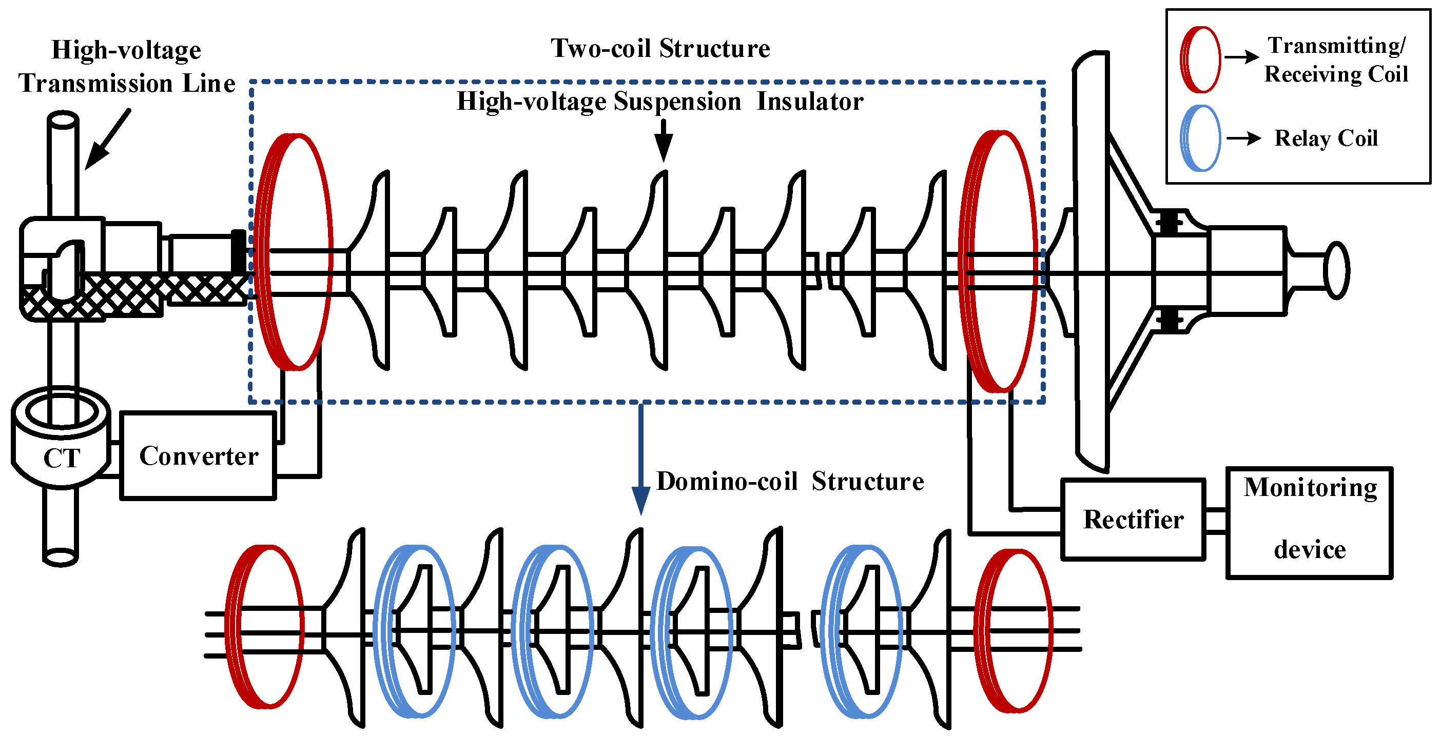
Figure 1. Block diagram of the traditional two-stage and domino-type WPT system used on HVTL.
Energies 15 04228 g001
Figure 2. Self-oscillating control diagram for the domino WPT systems.
Energies 15 04228 g002
Figure 3. Fundamental schematic diagram of a three-coil WPT system.
Energies 15 04228 g003
Figure 4. T-type equivalent circuit of the three-coil WPT system.
Energies 15 04228 g004
Figure 5. T-type equivalent circuit of the N-coil WPT system.
Energies 15 04228 g005
Figure 6. The waveforms of vt, it, vr, and ir at the four load-independent CV output frequencies (a) f0, (b) f1, (c) f2, and (d) f3.
Energies 15 04228 g006aEnergies 15 04228 g006b
Figure 7. Schematic of the experimental setup.
Energies 15 04228 g007
Figure 8. Photograph of the experimental setup.
Energies 15 04228 g008
Figure 9. Experimental waveforms of vt, it, vr, and ir at f0, f1, and f2, respectively.
Energies 15 04228 g009aEnergies 15 04228 g009b
Figure 10. Transient waveforms of vt, it, vr, and ir at f1 for the load resistance switching from 15 Ω to 7.5 Ω.
Energies 15 04228 g010
Table 1. Simulation parameters of the proposed domino WPT system.
NameValue
Input voltage (Vdc)5 V
Self-inductance (Li)49.2 µH
Compensated capacitance (Ci)51.5 nF
Mutual inductance (Mi)1.83 µH
Load resistance (RL) 15     Ω
Resonant frequency100 kHz
Table 2. Main parameters of the proposed domino WPT system.
SymbolValueSymbolValue
Vdc5 VR30.3 Ω
L149.2 µHL449.18 µH
C151.58 nFC451.5 nF
R10.3 ΩR40.3 Ω
L249.16 µHM11.83 µH
C251.52 nFM21.79 µH
R20.3 ΩM31.77 µH
L349.22 µHRL15 Ω
C351.6 nF
Table 3. Load-independent frequencies and corresponding voltage gains.
f0f1f2
Frequency (kHz)CalculatedMeasuredCalculatedMeasuredCalculatedMeasured
97.4296.2498.9699.21102.85102.20
Voltage gain0.160.110.700.640.590.55
Table 4. Variation in system parameters for the load resistance shifted from 15 Ω to 7.5 Ω.
Vt (RMS)It (RMS)Vr (RMS)Ir (RMS)Poutη
RL= 15 Ω4.39 V0.83 A2.83 V0.19 A0.54 W15%
RL′ = 7.5 Ω4.40 V0.91 A2.69 V0.36 A0.97 W24%
Publisher’s Note: MDPI stays neutral with regard to jurisdictional claims in published maps and institutional affiliations.