1. Introduction
The diesel engine is one of the most important power machines in the modern world. As the Chinese economy increases, the demand for commercial-vehicle power is increasing. The requirements for commercial diesel vehicles are not only a good power performance when driving on the road, but also a good torque performance when working on a project. It is known that the diesel working principle is compression–ignition, and a diesel engine working at the torque spot is different from that at the rated power spot. A diesel engine working at the max torque spot will increase the combustion gas pressure, which in turn will increase the combustion temperature. In modern diesel engines, the gas temperature can reach 2500 °C and higher, which can cause many problems [
1]. The most important one is a high temperature of the combustion parts. This problem is even more serious in duty commercial vehicles, because these commercial vehicles always need a diesel engine working at the max torque spot for an extended period.
The temperature field distribution on the surface of the piston reflects the thermal load on the aluminum–silicon (Al-Si) alloy piston during the working process of a diesel engine. The reduction in piston top temperature, especially in the throat area of the piston, will help improve the fatigue life of the piston under high torque loads and improve the overall reliability of the diesel engine. When the engine is working normally, the combustion chamber on the top of the piston is subjected to a continuous thermal shock of high-temperature gas, with a large temperature gradient and high thermal stress. However, the aluminum alloy piston material is close to the thermal stress limit of the material at about 370 °C, and thermal cracks will occur at 400 °C, resulting in failure phenomena such as oxidation cracking in the throat ring area of the piston [
2].
With the development of diesel engines, higher requirements have been put forward for their power density, resulting in an continuous increase in the thermal load of combustion chamber components such as diesel engine pistons, which seriously affects the operational reliability of diesel engines. Due to their good high-temperature resistance, thermal-barrier coatings have been widely used and continuously studied by a large number of researchers. Applying a thermal-barrier coating to the top surface of a diesel engine piston can protect the top of the piston from high-temperature gas corrosion without changing the structure of related parts. At the same time, the use of a thermal-barrier coating can also reduce the heat dissipation of the high-temperature gas in the combustion chamber through the piston and other components to achieve the purpose of improving the thermal efficiency of the engine. Therefore, in recent years, some scholars have applied thermal-barrier coatings to internal combustion engines to carry out corresponding research [
3,
4,
5,
6].
In order to determine the heat-transfer process that occurs in a cylinder, many studies have been conducted: Esfahanian et al. [
7] calculated the heat-transfer process in an engine piston crown using three different combustion boundary condition treatments. The results showed that using a spatial and time-averaged combustion side boundary condition was a suitable treatment method within engineering approximations. Cerit et al. [
8] conducted an experiment using 3D thermal analyses of a CCD-coated piston in an HCCI engine. The results showed that temperature distribution was a function of CCD thickness. The temperature developed on the top surface of the deposited region was significantly higher than that of the clean piston surface. The deposition on the piston surface had similar effects to other coating techniques. Some other specialists conducted studies regarding how to reduce the heat load in the piston. The most representative one used a ceramic-coated surface on the combustion side, which reduced the heat transfer into the piston. Cerit Muhammet et al. [
9] conducted temperature and thermal-stress analyses of a ceramic-coated aluminum alloy piston used in a diesel engine. The analysis results showed that the temperature and thermal-stress distribution matched a function of the coating thickness. The temperature on the surface of the coated region was significantly higher than that of the uncoated piston surface, the thermal efficiency of the engine was increased, and the piston body temperature was lower than usual. Ekrem et al. [
10] conducted a comparative evaluation among the temperature distributions on the uncoated piston surface and FGM-coated AlSi and steel piston surfaces. It was revealed that the surface temperature of the FGM-coated AlSi piston was higher than that of the uncoated AlSi piston. Moser et al. [
11] investigated the effect of thermal-barrier coatings on diesel engines by combining high-fidelity computational fluid dynamics (CFD) modeling of in-cylinder processes and combustion with finite element analysis (FEA) modeling of thermal-barrier coatings and the impact on metal engine components’ performances. Fei et al. [
12] used atmospheric plasma spraying to spray YSZ powder on the upper surface of an Al-Si alloy piston. The effect of using ceramic coating on the sailing performance of a diesel engine was studied. The temperature field results showed that under a 25% load, the top surface temperature of the coated piston was 30.91 °C higher than that of the conventional piston, and the thermal efficiency was improved by 5%.
In this study, as measured by the temperature plug method, the piston of a YC-6K diesel engine had temperature problems when working at the max torque spot. Therefore, the main purpose of this research was to solve the limitations of the high temperature and thermal load of an aluminum alloy piston on the development of commercial vehicle engines, and to provide thermal-fatigue protection for the piston. In this study, the protection effect of La2Zr2O7 thermal-barrier coatings with different thicknesses on the piston substrate was analyzed by means of finite element simulation analysis.
2. Methodology
2.1. Experimental Setup
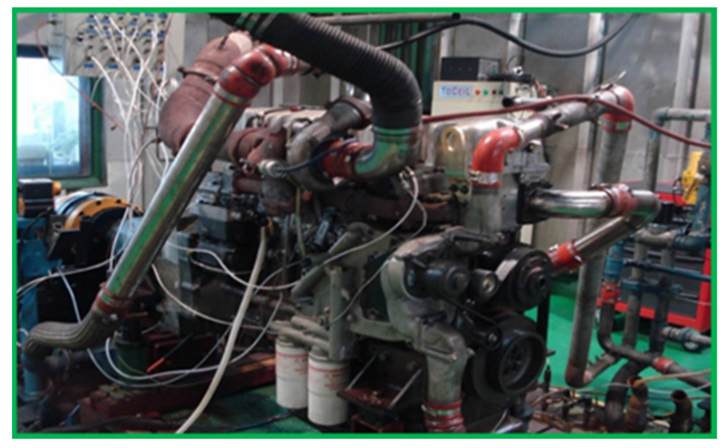
In order to study the influence of high-temperature conditions in the cylinder of a heavy-duty diesel engine on the reliability of the diesel engine’s piston at the torque spot, the diesel engine test in this paper was based on the engine’s rated torque spot. The engine used in this analysis was a YC6K direct injection diesel engine equipped with a turbocharger. The engine bench is shown in
Figure 1, and the relevant parameters of the engine are shown in
Table 1.
2.2. Temperature Measurements
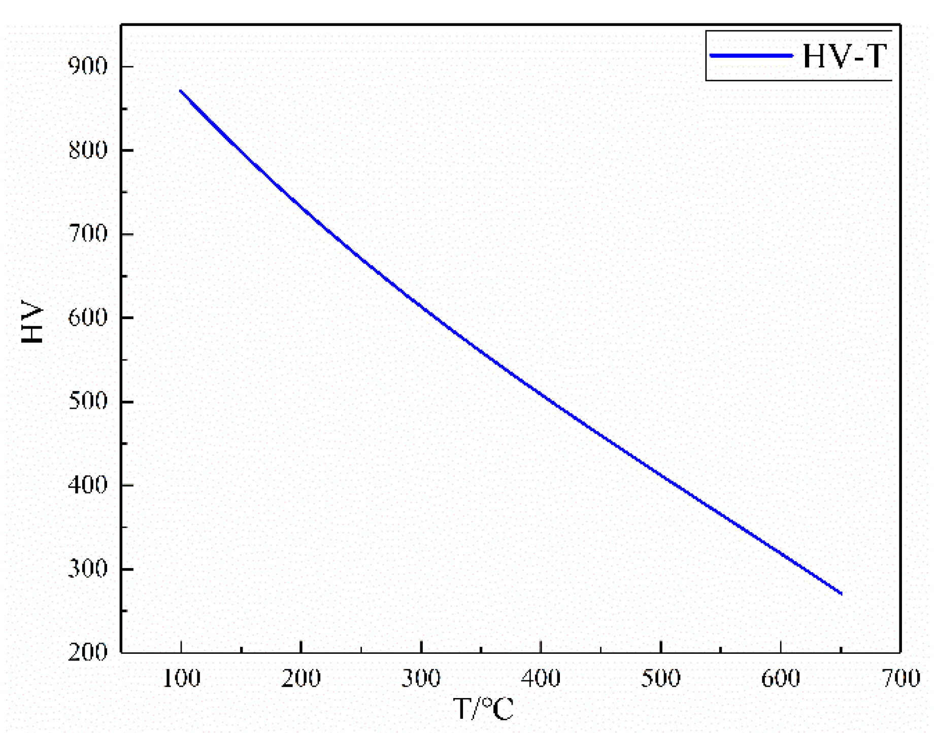
The piston temperature was measured using the temperature plug method. The temperature plug test method is ideal for testing systems that operate in a steady state for long periods of time [
9]. The hardness plugs used in this experiment were composed of Cr15, which was processed into screws and then subjected to a special heat treatment. The specially heat-treated temperature plugs had HV-T (hardness–temperature) properties as shown in
Figure 2.
A series of metal plug specimens were specially manufactured into screws of size M3 × 0.5 × 4 mm that were screwed in the top surface of piston to measure the piston surface temperature based on the property curve of material hardness versus anneal temperature, as shown in
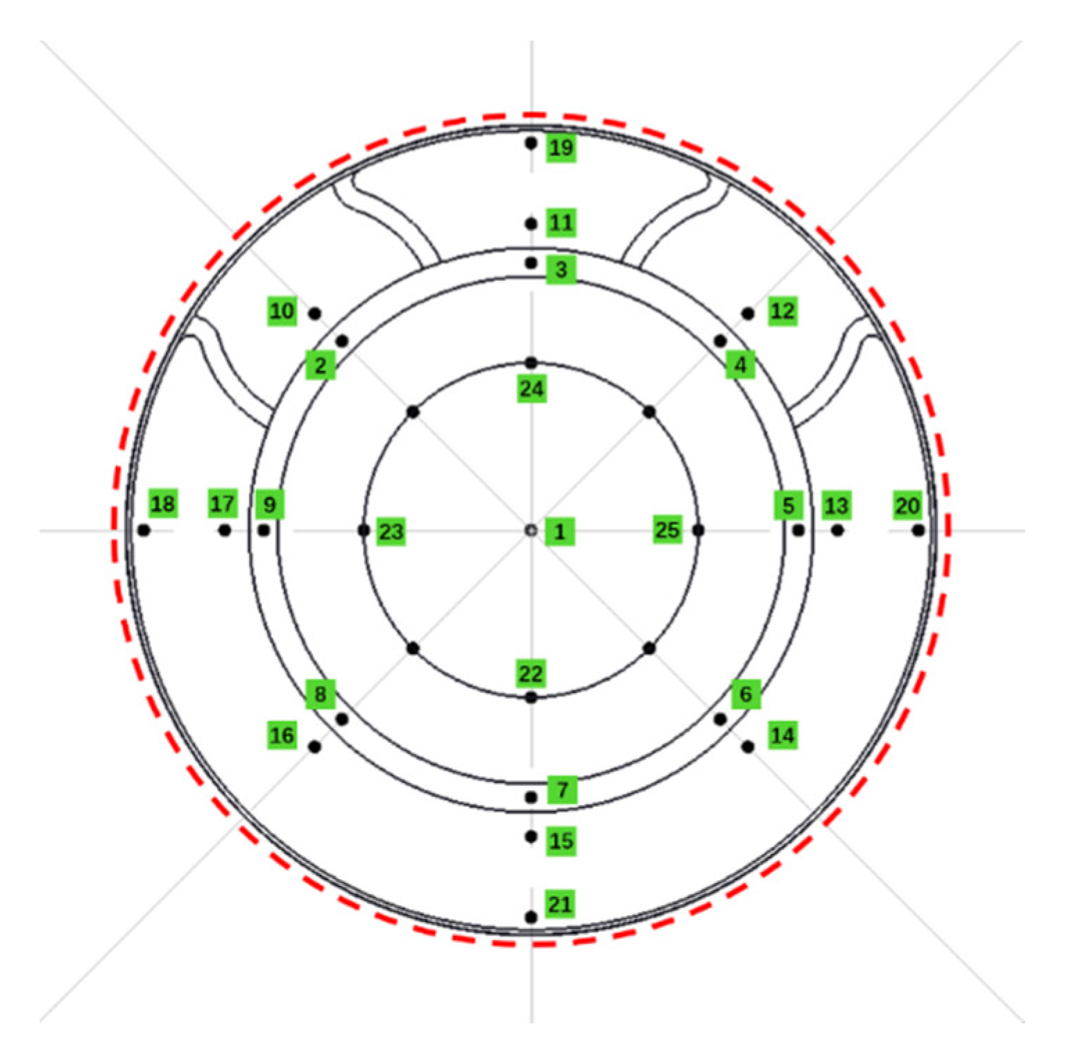
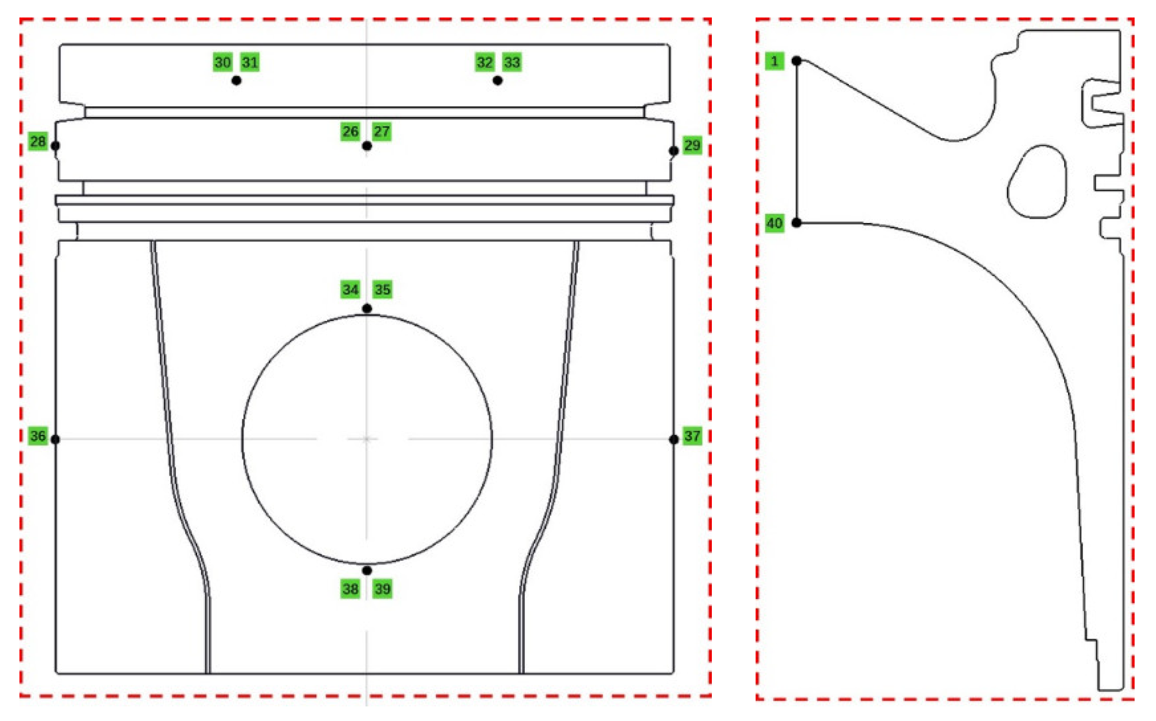
Figure 2. The distribution of the measure points (MPs) are shown in
Figure 3 and
Figure 4. The green numbers in
Figure 3 and
Figure 4 represent each measurement point. A photo of the piston after the experiment is shown in
Figure 5.
2.3. Temperature Measurements
A steady-state thermal analysis was performed using Ansys Workbench. The temperature field analysis of the piston adopted the steps shown in
Figure 6.
In this study, a heavy-duty commercial vehicle diesel engine piston composed of an aluminum–silicon alloy and cast iron was used as the research object. The finite element method was used to simulate and analyze the temperature field of the uncoated piston and the coated piston, and the results were compared with the experimental results.
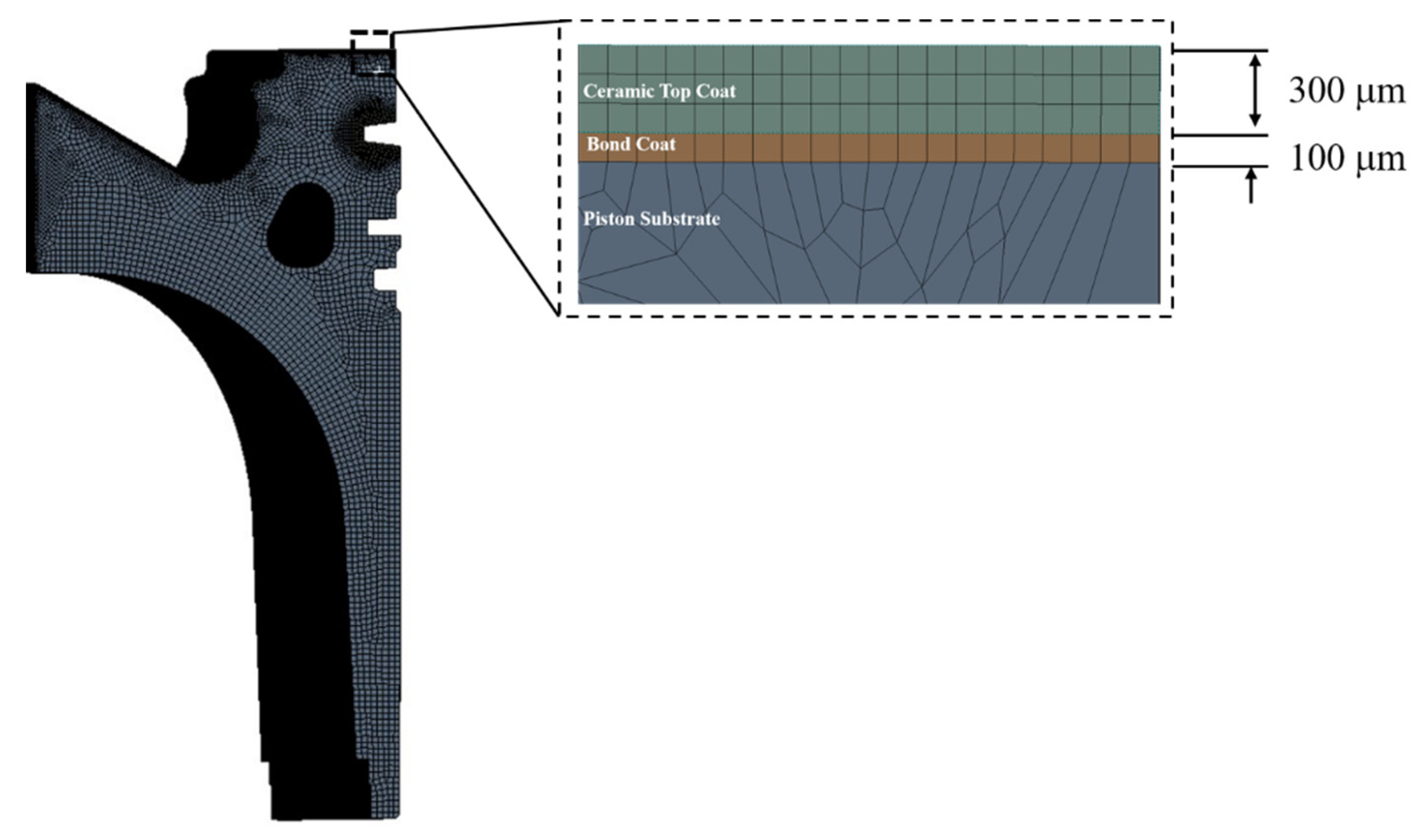
The finite element model of this study used a total of 1,686,172 elements and 6,915,062 nodes (see
Figure 6). The meshing used for the heat-transfer analysis of the La
2Zr
2O
7-coated piston was refined in Ansys Workbench. For the thermal analysis, the material properties of the piston substrate, La
2Zr
2O
7 barrier layer, and bonding layer are shown in
Table 2. The heavy-duty commercial vehicle diesel engine piston used is shown in
Figure 5. Since the piston was axisymmetric, in order to facilitate the calculation, only one-eighth of the piston model was selected for the simulation analysis. The one-eighth model of the piston and the coating thickness are shown in
Figure 7.
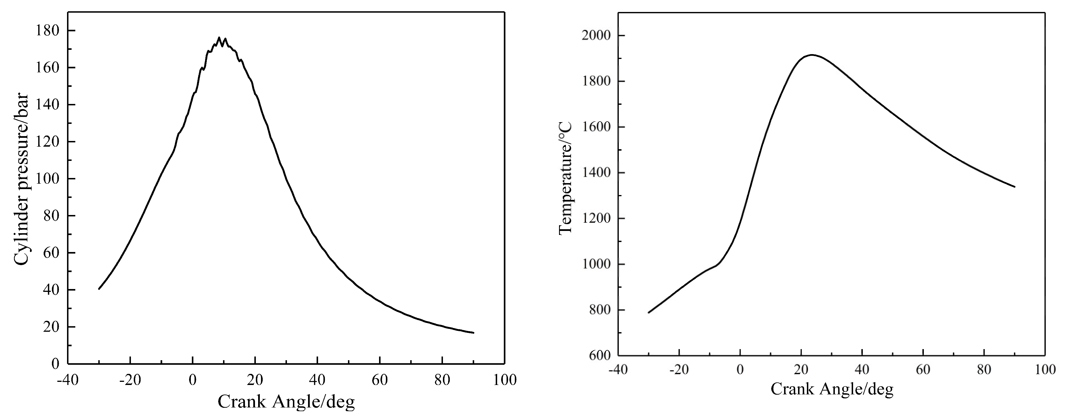
It is known that if the power of a diesel engine is steady, the temperature of the piston will remain constant. This means that the heat transfer, the convective heat transfer coefficient and the combustion gas temperature can be treated as equivalent constants over the working cycle time. The general way to calculate the constant gas temperature and the convective heat transfer coefficient is the time-average method. The constant convective heat transfer coefficient and temperature are the equivalent data in the entire working cycle.
The equation used to calculate the equivalent convective heat transfer coefficient is below:
The equation used to calculate the equivalent gas temperature is below:
where h
g is the transient convective heat transfer coefficient on the piston’s top surface; D is the diameter of the cylinder; C
m is the piston’s average moving speed; P
g is the transient pressure of the combustion gas (see
Figure 8); T
g is the transient temperature of the combustion gas (see
Figure 8); h
m is the equivalent convective heat transfer coefficient on the piston’s top surface; and T
m is the equivalent temperature of the combustion gas.
The simulation analysis showed the temperature distributions on the different surfaces of the TBC piston, and the results were compared with those of the uncoated piston to verify the accuracy of the simulation model. Since the thermal-boundary conditions of the piston were very complex, the thermal-boundary conditions for temperature and medium heat transfer coefficient were calculated in this study based on empirical formulas and experimentally measured values in the case of maximum torque. The thermal-boundary conditions calculated in this manner for the different elements are shown in
Table 3.
3. Results and Discussions
3.1. Temperature Plug Measurement Results
A typical 100% maximum torque point condition (named the max torque spot) was selected for the experiment, and the temperature was measured through the temperature plug. This condition was a typical heavy load point for commercial vehicle diesel engines. The operation process of loading this condition is shown in
Table 4. In order to keep the maximum piston temperature stable, the test was run for 60 min at the highest torque. The single-cylinder power at the maximum torque point was 49.91 kW.
As can be seen in
Figure 3 to
Figure 5, the piston was an axisymmetric model, and the heat-transfer path was also axisymmetric. Therefore, in order to reduce the measurement error, the temperature data of these 40 measurement points were compressed into the temperature data of 11 measurement points. The simplified measurement point distribution is shown in
Figure 9. The values for these 11 measurement points were calculated from the 40 measurement points shown in
Figure 3 and
Figure 4, and each value was an average of similar locations. The values of these 11 measurement points are shown in
Table 5.
3.2. Simulation of the Piston Body Temperature
The real piston was a 3D model in the geometry, and has many details that made the model and heat transfer complex. It is known that the main heat-transfer path is from the piston’s top surface to the cooling water and the lubricating oil, which means the slight dimensional change had no impact on the main heat transfer. In order to reduce the calculation quantity, in this paper, a simplified 3D axi-symmetric FEM model was used to simulate the thermal results of the piston. The FEM model reduced the slight details that slightly impacted the main heat transfer, such as the radius of the chamber, the small holes, and so on. The FEM model is shown in
Figure 7; it was built using PLANE55 elements with an element size of 1 mm.
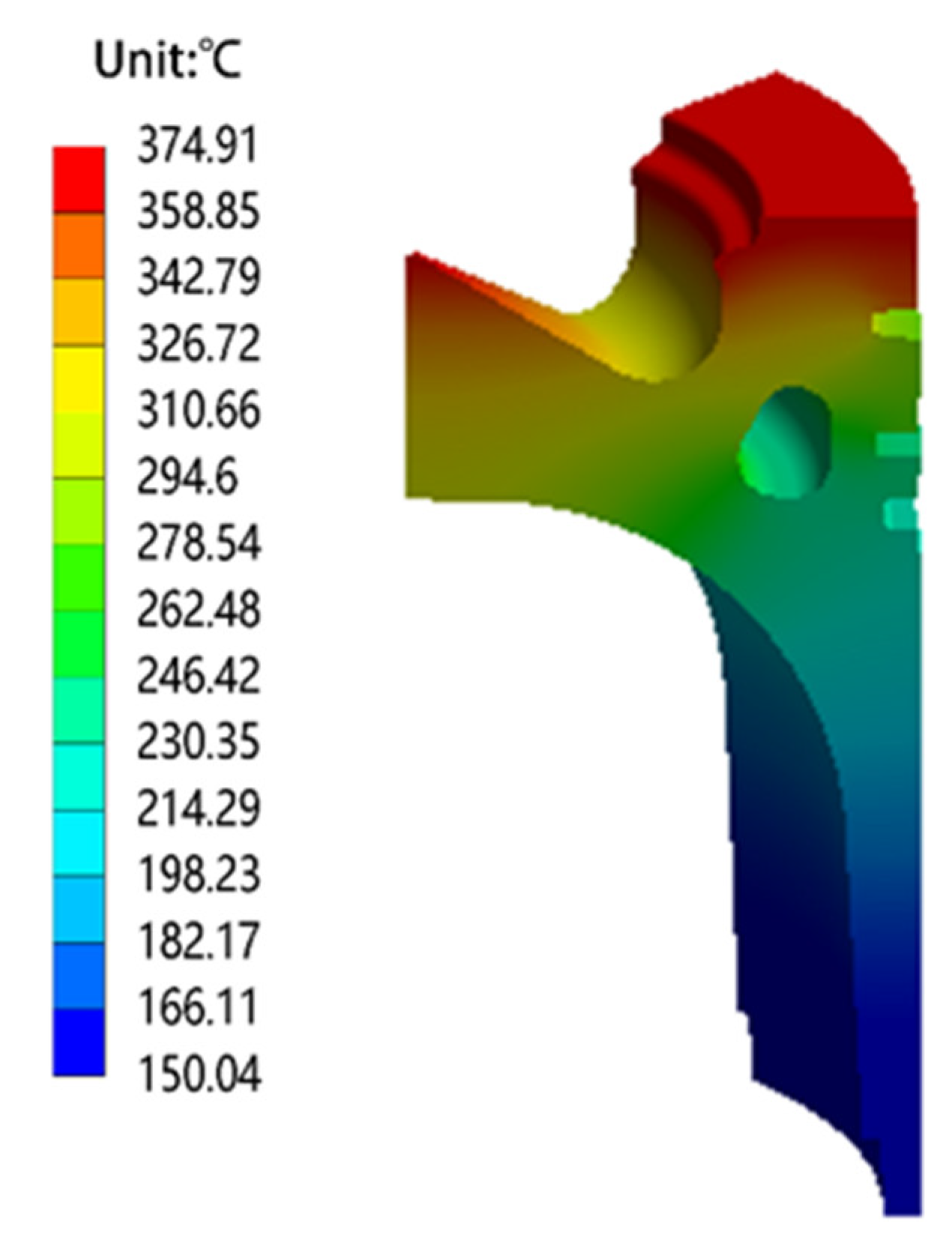
The simulated temperature values at the end of the iterations are shown in
Figure 10. The temperature results for the piston corresponding to the reference point under the maximum torque point condition of the simulation analysis were compared with the test results of the temperature plug, as shown in
Table 6. The deviation between these results was less than 6%, which was within the acceptable range, indicating that the established piston model had high accuracy and reliability.
It can be seen in
Table 6 that the maximum piston temperature at the max torque spot exceeded 370 °C, which was close to the maximum safe temperature of the piston material. This would adversely affect the safe operation of the diesel engine, so this paper studied the thermal-protection ability of the La
2Zr
2O
7 coating on the piston substrate by means of a numerical simulation.
3.3. Piston Temperature Field of Thermal-Barrier Coatings with Different Thicknesses
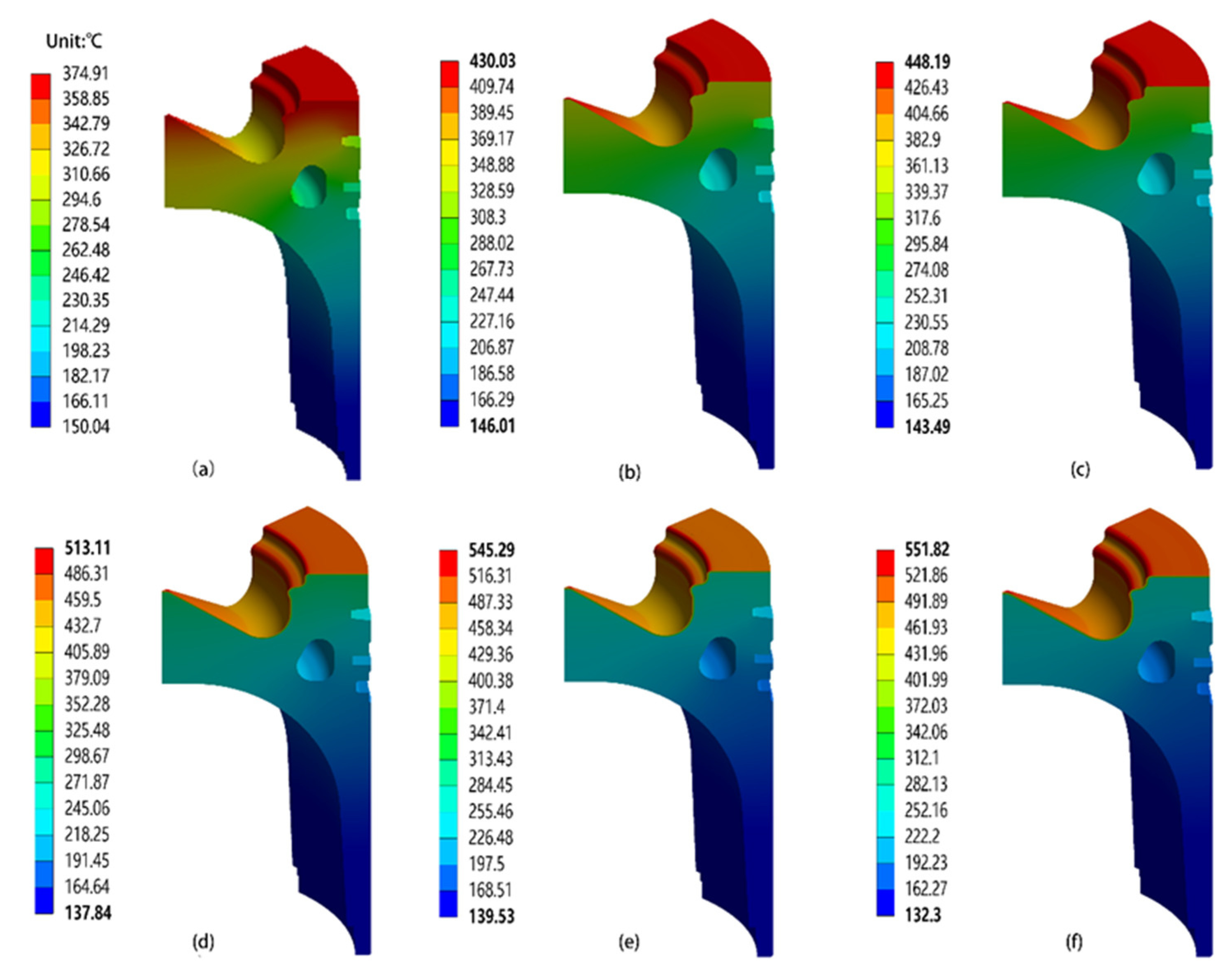
In this study, the temperature field of a piston with a bonding layer of 0.1 mm and a thermal insulation layer of different thicknesses ((a) no thermal barrier coating, (b) 0.2 mm, (c) 0.3 mm, (d) 0.5 mm, (e) 0.7 mm, (f) 0.9 mm) was simulated, as shown in
Figure 11 and
Figure 12.
It can be seen in
Figure 11 that the maximum temperature of the ceramic coating of the piston with a thermal-barrier coating reached 551.82 °C, which occurred in the throat ring area of the piston’s combustion chamber.
Figure 12 shows the temperature of the thermal barrier coating the piston substrate; the maximum temperature of the piston was 267.46 °C, and the lowest temperature was 132.3 °C.
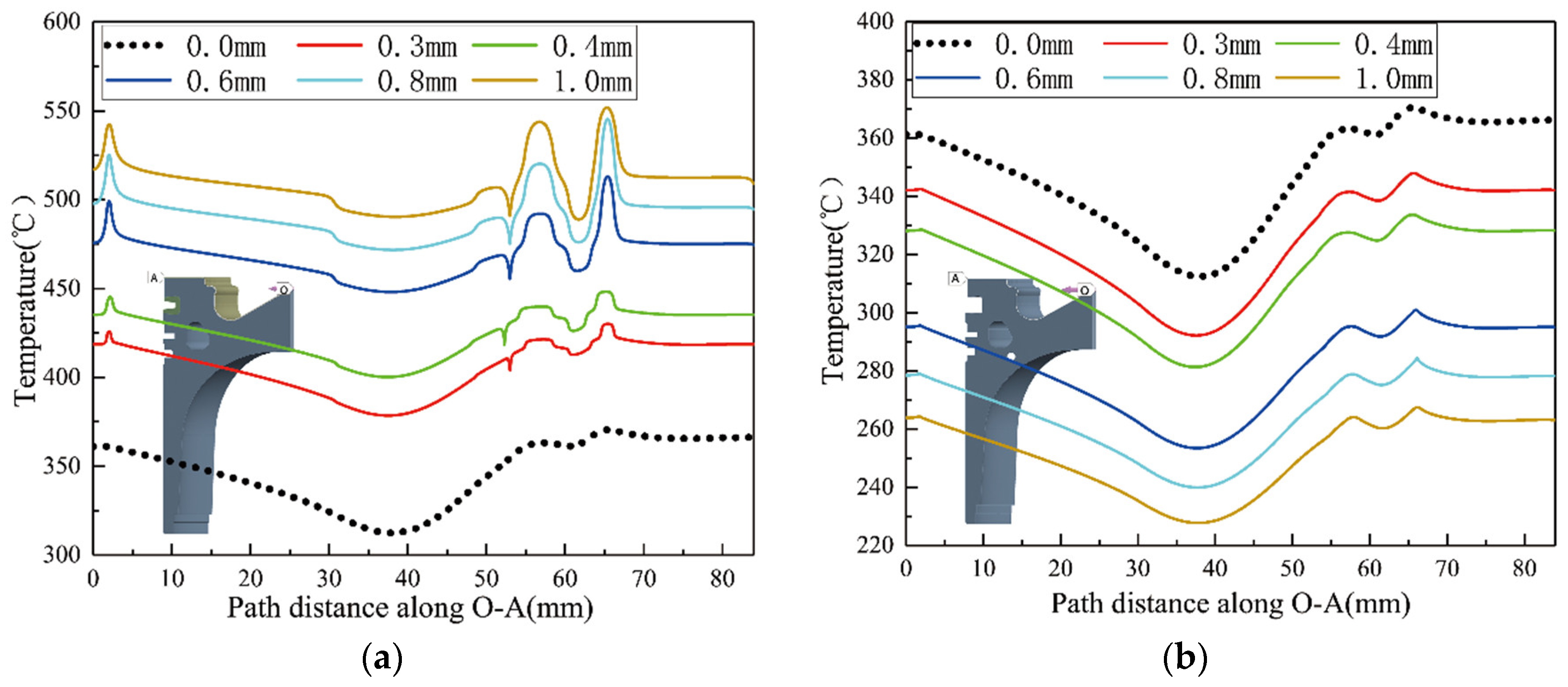
The temperature variation could be visually analyzed by selecting the path OA from the center point O of the combustion chamber on the top of the piston to the point A in the radial direction (shown by the lines in
Figure 13) and extracting the temperature values of the nodes along the path. The temperature values on the top ceramic coating of the TBC piston and the path OA on top of the piston substrate are shown in
Figure 13a,b, respectively.
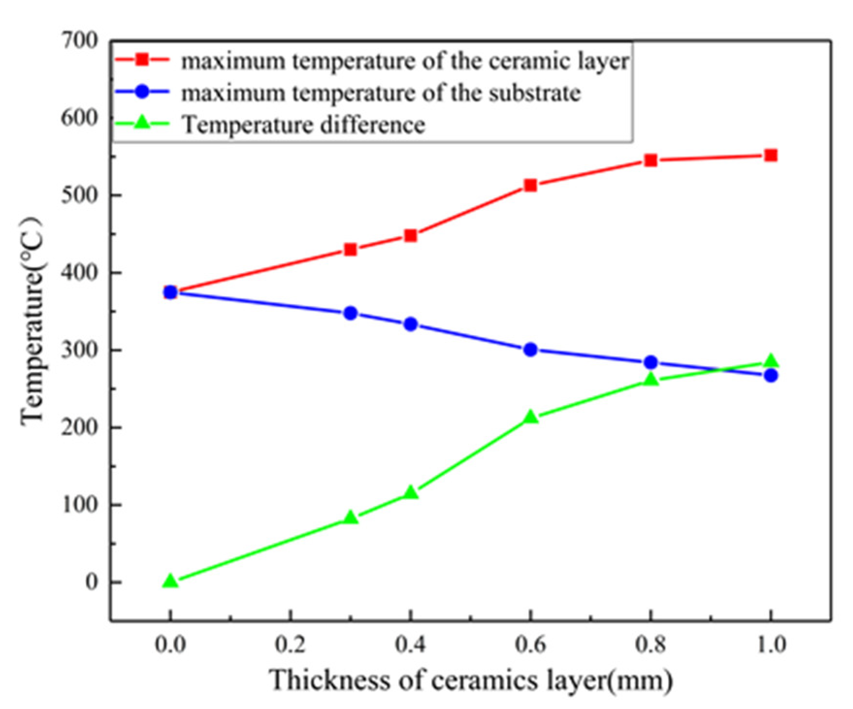
As shown in
Figure 14, the maximum temperature at the top of the piston increased with the thickness of the ceramic layer. Specifically, as the thickness increased from 0.3 mm to 1.0 mm, the maximum temperature increased from 430.0 °C to 551.8 °C. For the piston substrate, the maximum temperature decreased from 347.9 °C to 267.5 °C as the ceramic coating thickness increased from 0.3 mm to 1.0 mm. With the addition of the ceramic layer, the thermal-insulation properties were also enhanced: the temperature difference increased significantly from 82.1 °C to 284.4 °C.
As the thickness of the ceramic layer increased, the increasing trend of the temperature difference gradually became slower, which indicated that when the ceramic reached the critical thickness, a further increase in the ceramic thickness was less effective in reducing the temperature of the piston base (
Figure 14).
4. Conclusions
In order to solve the problem of the high thermal load of a piston when the engine is working at the maximum torque spot, this study took a commercial vehicle engine piston as the research object. By using temperature plugs to measure the temperatures of the corresponding points of the piston combined with the finite element method, the piston was modeled, and the corresponding simulation analysis was carried out. The error between the numerical simulation results of the temperature field and the measurement results was within 6%, which indicated that the piston model was accurate and could be used to simulate and analyze the heating condition of the piston.
On the basis of the above-mentioned verified 3D model of the engine piston, this study designed an engine piston with a double-layer coating structure, with NiCoCrAlY alloy as the bonding layer and La2Zr2O7 ceramic as the thermal insulation layer to improve the resistance of the piston to high thermal loads and high temperatures.
The thermal analysis results showed that the overall temperature of the engine piston without a coating was higher, especially the combustion chamber and piston crown; the maximum temperature of the throat ring area of the combustion chamber exceeded 370 °C, which was close to the limit of the aluminum alloy piston material, indicating that the combustion chamber throat may have been exposed to excessive thermal loads.
The results of thermal analysis of the piston using La2Zr2O7 coatings of different thicknesses showed that the highest temperature occurred on the top ceramic coating, but this temperature was much lower than the failure temperature of the La2Zr2O7 ceramic material, indicating that it operated under safe conditions. The temperature of the piston substrate after application of the thermal-barrier coating was significantly lower than that of the unsprayed piston substrate, so coating the piston with a La2Zr2O7 coating could effectively reduce the temperature of the piston substrate and improve its ability to withstand higher thermal loads. However, with the increase in the thickness of the ceramic coating, the temperature of the aluminum alloy substrate gradually decreased, but the range of decrease gradually weakened.
Author Contributions
Conceptualization and formal analysis, C.F.; Investigation, T.L. and Z.S.; Methodology, C.F.; Supervision Z.Q.; Software, Z.S.; Writing—original draft preparation, C.F. and Z.S. All authors have read and agreed to the published version of the manuscript.
Funding
This research received no external funding.
Institutional Review Board Statement
Not applicable.
Informed Consent Statement
Not applicable.
Data Availability Statement
Not applicable.
Conflicts of Interest
The authors declare no conflict of interest.
Nomenclature
| TBC | Thermal-barrier coating |
| La2Zr2O7 | Lanthanum zirconate |
| Al-Si | Aluminum–silicon |
| FEM | Finite element method |
| MP | Measure Point |
| HV | Vickers hardness |
References
- Heywood, J.B. Internal Combustion Engine Fundamentals; McGraw-Hill: New York, NY, USA, 1988. [Google Scholar]
- Liu, Y.; Reitz, R.D. Modeling of heat conduction within chamber walls for multidimensional internal combustion engine simulations. Int. J. Heat Mass Transf. 1998, 41, 859–869. [Google Scholar] [CrossRef]
- Beardsley, M.B.; Happoldt, P.G.; Kelley, K.C.; Rejda, E.F.; Socie, D.F. Thermal Barrier Coatings for Low Emission, High Efficiency Diesel Engine Applications; SAE International: Warrendale, PA, USA, 1999. [Google Scholar]
- Cheng, W.; Wong, V.; Gao, F. Heat Transfer Measurement Comparisons in Insulated and Non-Insulated Diesel Engines; SAE International: Warrendale, PA, USA, 1989. [Google Scholar]
- Venkadesan, G.; Muthusamy, J. Experimental investigation of Al2O3/8YSZ and CeO2/8YSZ plasma sprayed thermal barrier coating on diesel engine. Ceram. Int. 2019, 45, 3166–3176. [Google Scholar] [CrossRef]
- Sivakumar, G.; Kumar, S.S. Investigation on effect of Yttria Stabilized Zirconia coated piston crown on performance and emission characteristics of a diesel engine. Alex. Eng. J. 2014, 53, 787–794. [Google Scholar] [CrossRef] [Green Version]
- Esfahanian, V.; Javaheri, A.; Ghaffarpour, M. Thermal analysis of an Si engine piston using different combustion boundary condition treatments. Appl. Therm. Eng. 2006, 26, 277–287. [Google Scholar] [CrossRef]
- Cerit, M.; Hakan, S.S. Thermal analysis of a combustion chamber surround by deposits in an HCCI engine. Appl. Therm. Eng. 2013, 50, 81–88. [Google Scholar] [CrossRef]
- Cerit, M.; Coban, M. Temperature and thermal stress analyses of a ceramic-coated aluminum alloy piston used in a diesel engine. Intern. J. Therm. Sci. 2004, 77, 11–18. [Google Scholar] [CrossRef]
- Ekrem, B. Thermal analysis of functionally graded coating AlSi alloy and steel pistons. Surf. Coat. Technol. 2008, 202, 3856–3865. [Google Scholar]
- Moser, S.; Edwards, K.D.; Schoeffler, T.; Filipi, Z. CFD/FEA Co-Simulation Framework for Analysis of the Thermal Barrier Coating Design and Its Impact on the HD Diesel Engine Performance. Energies 2021, 14, 2044. [Google Scholar] [CrossRef]
- Fei, C.-G.; Qian, Z.-Q.; Ren, J.; Zhou, X.-J.; Zhu, S.-W. Numerical and Experimental Research on Thermal Insulation Performance of Marine Diesel Engine Piston Based on YSZ Thermal Barrier Coating. Coatings 2021, 11, 765. [Google Scholar] [CrossRef]
- Cao, X.-Q.; Vassen, R.; Stoever, D. Ceramic materials for thermal barrier coatings. J. Eur. Ceram. Soc. 2004, 24, 1–10. [Google Scholar] [CrossRef]
- Sharma, J.K.; Raj, R.; Kumar, S.; Jain, R.K.; Pandey, M. Finite element modelling of Lanthanum Cerate (La2Ce2O7) coated piston used in a diesel engine. Case Stud. Therm. Eng. 2021, 25, 100865. [Google Scholar] [CrossRef]
- Yonushonis, T.M. Overview of thermal barrier coatings in diesel engines. J. Therm. Spray Technol. 1997, 6, 50–56. [Google Scholar] [CrossRef] [Green Version]
- Gok, M.G.; Karabas, M. Production of Re doped La2Zr2O7 based TBCs and numerical analysis of their use on IC engine piston surface. Ceram. Int. 2022, 48, 11173–11180. [Google Scholar] [CrossRef]
Figure 1.
The YC6K test diesel.
Figure 1.
The YC6K test diesel.
Figure 3.
The distribution of the MPs in the combustion chamber.
Figure 3.
The distribution of the MPs in the combustion chamber.
Figure 4.
The distribution of the MPs on the other side.
Figure 4.
The distribution of the MPs on the other side.
Figure 5.
The experimented piston.
Figure 5.
The experimented piston.
Figure 6.
Methodology used for thermal analysis.
Figure 6.
Methodology used for thermal analysis.
Figure 7.
The one-eighth piston model and thickness of the thermal-barrier coating.
Figure 7.
The one-eighth piston model and thickness of the thermal-barrier coating.
Figure 8.
Test−measured cylinder pressure and temperature.
Figure 8.
Test−measured cylinder pressure and temperature.
Figure 9.
The simplified model with the 11 MPs.
Figure 9.
The simplified model with the 11 MPs.
Figure 10.
Temperature distribution of the uncoated piston.
Figure 10.
Temperature distribution of the uncoated piston.
Figure 11.
Temperature distributions of pistons coated using different thicknesses. (a) shows the temperature field of the uncoated piston, and (b–f) shows the overall temperature field of the piston with a total coating thickness of 0.3 mm, 0.4 mm, 0.6 mm, 0.8 mm and 1.0 mm.
Figure 11.
Temperature distributions of pistons coated using different thicknesses. (a) shows the temperature field of the uncoated piston, and (b–f) shows the overall temperature field of the piston with a total coating thickness of 0.3 mm, 0.4 mm, 0.6 mm, 0.8 mm and 1.0 mm.
Figure 12.
Temperature distributions of piston substrates coated using different thicknesses. (a) shows the temperature field of the unpainted piston, and (b–f) shows the temperature field of the piston aluminum alloy substrate with the total coating thickness of 0.3 mm, 0.4 mm, 0.6 mm, 0.8 mm and 1.0 mm.
Figure 13.
(a) Top surface-temperature distribution along O-A path distance; (b) substrate surface-temperature distribution along O-A path distance.
Figure 13.
(a) Top surface-temperature distribution along O-A path distance; (b) substrate surface-temperature distribution along O-A path distance.
Figure 14.
Effects of ceramic-layer thickness on TBC piston temperature.
Figure 14.
Effects of ceramic-layer thickness on TBC piston temperature.
Table 1.
The technical specifications of the test engine.
Table 1.
The technical specifications of the test engine.
| Engine Parameters | Specifications |
|---|
| Engine model | YC6K diesel engine |
| Number of cylinders | 6 |
| Type of operation | Four-stroke |
| Bore diameter(mm) | 129 |
| Stroke(mm) | 155 |
| Compression ratio | 17:1 |
| Capacity/L | 12.155 |
| Rated power/kw | 353 |
| Rated speed/(r·min−1) | 1900 |
| Type of injection | Direct injection |
| Aspiration | Turbocharged |
Table 2.
The material properties of La
2Zr
2O
7 barrier layer, bonding layer and piston substrate [
13,
14,
15,
16].
Table 2.
The material properties of La
2Zr
2O
7 barrier layer, bonding layer and piston substrate [
13,
14,
15,
16].
| Material | Thermal Conductivity
(W/m °C) | Thermal
Expansion
10−6 (1/°C) | Density (kg/m3) | Specific Heat (J/kg °C) | Young’s
Modulus
(GPa) | Poisson’s
Ratio |
|---|
| Al-Si alloy | 155 | 21 | 2700 | 960 | 90 | 0.3 |
| Steel | 79 | 12.2 | 7300 | 500 | 200 | 0.3 |
| La2Zr2O7 | 1.2 | 9.1 | 6300 | 650 | 63 | 0.3 |
| NiCoCrAlY | 16.1 | 17.5 | 7870 | 764 | 86 | 0.3 |
Table 3.
Thermal-boundary conditions of the different elements.
Table 3.
Thermal-boundary conditions of the different elements.
| Thermal-Boundary Conditions | Temperature (°C) | Convective Heat Transfer Coefficient (W/m2 K) |
|---|
| Combustion chamber | 700 | 1151.6 |
| Piston fire shore | 120 | 66.59 |
| Upper part of the first ring | 120 | 359.34 |
| Middle part of the first ring | 115 | 201.86 |
| Lower part of the first ring | 110 | 359.34 |
| Second ring | 93 | 200 |
| Piston skirt | 93 | 136 |
| Cooling oil cavity | 120 | 1800 |
Table 4.
The operation process to load condition.
Table 4.
The operation process to load condition.
| STEP | Duration/(min) | Speed/(r/min) | Torque/(N·m) |
|---|
| 1 | 15 | 1000 | 440 |
| 2 | 20 | 1300 | 1100 |
| 3 | 60 | 1300 | 2200 |
| 4 | 5 | 1300 | 1200 |
| 5 | 5 | 1200 | 800 |
| 6 | 5 | 1100 | 600 |
| 7 | 5 | 1000 | 400 |
| 8 | 5 | 900 | 220 |
Table 5.
The average values of the 11 MPs.
Table 5.
The average values of the 11 MPs.
| MP_Num | Max Torque Spot Temperature/°C |
|---|
| 1 | 367 |
| 2 | 310 |
| 3 | 373 |
| 4 | 367.5 |
| 5 | 361.25 |
| 6 | 344.25 |
| 7 | 252 |
| 8 | 185 |
| 9 | 169.5 |
| 10 | 145.5 |
| 11 | 310 |
Table 6.
Comparison between the simulated results and measured results at the max torque spot.
Table 6.
Comparison between the simulated results and measured results at the max torque spot.
| MP_Num | Simulated Value | Experimental Value | Relative Error/% |
|---|
| MP1 | 365.5 °C | 367.00 °C | 0.41% |
| MP2 | 311.95 °C | 310.00 °C | 0.63% |
| MP3 | 367.23 °C | 373.00 °C | 1.55% |
| MP4 | 372.51 °C | 367.50 °C | 1.36% |
| MP5 | 369.88 °C | 361.25 °C | 2.39% |
| MP6 | 350.3 °C | 344.25 °C | 1.76% |
| MP7 | 260.48 °C | 252.00 °C | 3.37% |
| MP8 | 191.11 °C | 185.00 °C | 3.3% |
| MP9 | 178.1 °C | 169.5.00 °C | 5.07% |
| MP10 | 152.11 °C | 145.50 °C | 4.54% |
| MP11 | 307.95 °C | 310.00 °C | 0.66% |
| Publisher’s Note: MDPI stays neutral with regard to jurisdictional claims in published maps and institutional affiliations. |
© 2022 by the authors. Licensee MDPI, Basel, Switzerland. This article is an open access article distributed under the terms and conditions of the Creative Commons Attribution (CC BY) license (https://creativecommons.org/licenses/by/4.0/).


