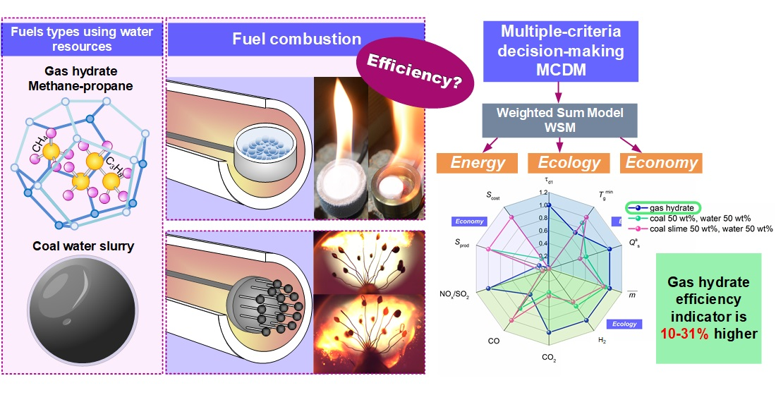
Article

Prospects of Using Gas Hydrates in Power Plants

Heat and Mass Transfer Simulation Laboratory, National Research Tomsk Polytechnic University, 30 Lenin Avenue, 634050 Tomsk, Russia
*
Author to whom correspondence should be addressed.
Energies 2022, 15(12), 4188; https://doi.org/10.3390/en15124188
Submission received: 18 April 2022 / Revised: 1 June 2022 / Accepted: 6 June 2022 / Published: 7 June 2022
(This article belongs to the Collection Featured Papers in Geo-Energy)

Abstract

:
By adding water to fuels, several objectives are pursued, with the main ones being to stabilize combustion, minimize the anthropogenic gaseous emissions, homogenize and stabilize the fuel, as well as improve its fire and explosion safety. Water can be injected into the furnace as droplets or vapor and introduced as part of fuel samples. Water often serves as a coupling or carrier medium for the delivery of the main fuel components. In this paper, we compare the combustion behaviors of high-potential slurry fuels and gas hydrates. We also analyze the contribution of in slurries and gas hydrates to the combustion process. The values of relative combustion efficiency indicators are determined for gas hydrates and slurry fuels. The conditions are identified in which these fuels can be burned effectively in power plants. The research findings can be used to rationalize the alternative ways of using water resources, i.e., gas hydrate powder and promising composite fuel droplets. The results can also help predict the conditions for the shortest possible ignition delay, as well as effective combustion of gas hydrates as the most environmentally friendly new-generation alternative fuel.

Graphical Abstract

1. Introduction

1.1. Gas Hydrates

Alternative energy sources are becoming increasingly attractive with the growing global energy consumption. This is especially true for gas hydrates [1,2]. These compounds of water and gas—most commonly methane (up to 90%)—are formed at low temperatures and high pressures [3]. Hydrogen-bonded water molecules form a stable cage, and methane molecules are trapped within. In general, there are three main structures of gas hydrates: structural I (sI), structural II (sII), and structure H (sH) [4]. In sI hydrate, water molecules are automatically arranged to form cavities with 512 cages and 51262 cages [4,5]. Natural gas hydrates are concentrated in deep water areas, mostly on the seabed and ocean floor. Marine hydrates contain up to 90% of methane. The largest hydrate accumulations are located in the southeast and west of North America, near Canada, Peru, Costa Rica, South Korea, Mexico, and Japan. All these countries border the Pacific Ocean, which is the most hydrate-rich zone [6,7]. Gas hydrate deposits were also discovered in South China Sea and on the Arctic seafloor. In the World Ocean, gas hydrates are most often discovered on continental slopes and shelves [8]. This is attributed to the accumulation of sediments with elevated content of organic matter, which is a source of thermogenic and microbial methane [9]. If there is a source of methane, marine gas hydrates are formed at a depth of over 320 m. The depth of the seafloor at which hydrates are formed depends on the bottom water temperature: the higher the temperature, the greater the sea depth is needed for hydrate formation [10]. The sea level reduction and increase in the bottom water temperature leads to the destruction of gas hydrates and release of methane into water and the atmosphere [11] with an adverse effect on the environment. Researching gas hydrates is thus a topical objective in terms of environmental protection. A comprehensive review on studies of natural gas hydrates is proposed in [4].
Discovery of gas hydrate deposits is a crucial and complicated part of gas hydrate research. Gas hydrates can be detected by hydroacoustic survey, seismic sounding, geophysical measurements, and electromagnetic exploration [12,13,14]. The most popular method of hydrate detection on the seabed and ocean floor is standard and high-frequency seismic exploration [13,15]. Seismic surveys can be two-dimensional (2D) and three-dimensional (3D) [16]. The 2D survey data reveal the lower position of hydrate-bearing sediments with a frequency of 30–120 Hz. A 3D seismic survey determines the top and bottom boundaries of hydrate-bearing sediments and provides data on the hydrate concentration in the sediments. Geophysical measurements are extra sensitive to gas hydrates but technically challenging [17]. When marine controlled-source electromagnetics is used, the data on hydrate-saturated sediments are acquired using transmitters on the seafloor and the corresponding receiver [12]. Drilling for gas hydrates using specialized rigs (Japan, Korea, and China) has also become popular over the recent years [18,19].
In addition to gas hydrate detection methods, researchers focus on the technologies of natural gas production from hydrates, hydrate dissociation, and self-preservation, as well as hydrate ignition and combustion behavior [20]. Natural gas can be recovered from hydrates by means of three main technologies [4,21,22,23,24,25]: using inhibitors, thermal method, and combined method. Injecting inhibitors into a hydrate reservoir disturbs the phase equilibrium of gas hydrates [26]. Saline or organic solutions can serve as inhibitors. The thermal method makes it possible to produce gaseous methane at a rate that is an order of magnitude higher than what depressurization and inhibitor injection can provide [27]. However, thermal stimulation requires a detailed study of the dissociation process and gas flow dynamics. The combined method involving depressurization and thermal exposure at the same time is considered the most promising one [24]. Heat can be supplied in the form of electric heating or hot water or vapor. Hot water injection was found [24] to enhance thermal convection and to accelerate the gas hydrate dissociation.
The understanding of the dissociation process is an important part of gas hydrate research. The dissociation kinetics affects both the natural gas production from hydrates, and the ignition and combustion behavior. In turn, the gas hydrate dissociation rate is affected by a multitude of factors: hydrate particle size, type of hydrate, pressure, and temperature. Research findings on the dissociation kinetics of natural gas hydrates from marine hydrate deposits are presented in [28]. Higher temperature and mixing speed significantly stimulated the dissociation of gas hydrate, whereas the granule size exhibited a negligible effect. In addition, a highly accurate kinetic model was constructed to describe the methane hydrate dissociation, which simultaneously reflected the impact of pressure, temperature, and mixing speed on the seemingly constant hydrate dissociation rate [28]. The authors in [29,30] showed that the methane hydrate dissociation rate varies by up to 5 orders of magnitude in the temperature range of 230–268 K. The impact of temperature and external pressure on the dissociation rate was studied by Stern et al. [31]. Misyura [32] investigated the dissociation of different gas hydrates during their combustion. It was established [32] that the dissociation rate of methane–propane double hydrate is higher than that of methane hydrate. The dissociation rate of methane–isopropanol hydrate is much lower than that of methane hydrate and methane–propane double hydrate. The flame front velocity is highly nonlinear due to the gas hydrate self-preservation effect, which emerges in the course of dissociation at negative temperatures [33]. This is a reduction in the rate of hydrate decomposition into gas and water up to its complete stop [34]. According to Stern et al. [31], the gas hydrate self-preservation is based on the morphological changes inside the hydrate.
Not only dissociation but also combustion of gas hydrate is a subject of large-scale research [35,36,37,38]. The combustion of methane hydrate has been poorly studied due to the complex characteristics of the multiphase transition and the difficulty of working with fuel that decomposes at standard temperature and pressure [39]. The combustion process can be subdivided into the following stages: ice shell melting, water evaporation, and flammable component combustion [35]. The main feature of gas hydrate combustion is the hydrate-dissociated reaction of the gas because such fuels consist of gas and water molecules. The water content of the fuel has a significant effect on its stability, ignition, and combustion characteristics. The effect of the introduction of hydrous ethanol with different water content on the operation of a diesel engine was studied in [40]. The effect of water on the stability of isopropanol–butanol–ethanol (IBE) and diesel fuel was studied in [41]. It has been established that the use of a small amount of water can, to a certain extent, improve the environmental and energy performance of a diesel engine. Water evaporation and water vapor formation are considered the main factors influencing the hydrate combustion kinetics. A water film is formed at the surface of gas hydrate while it is burning [
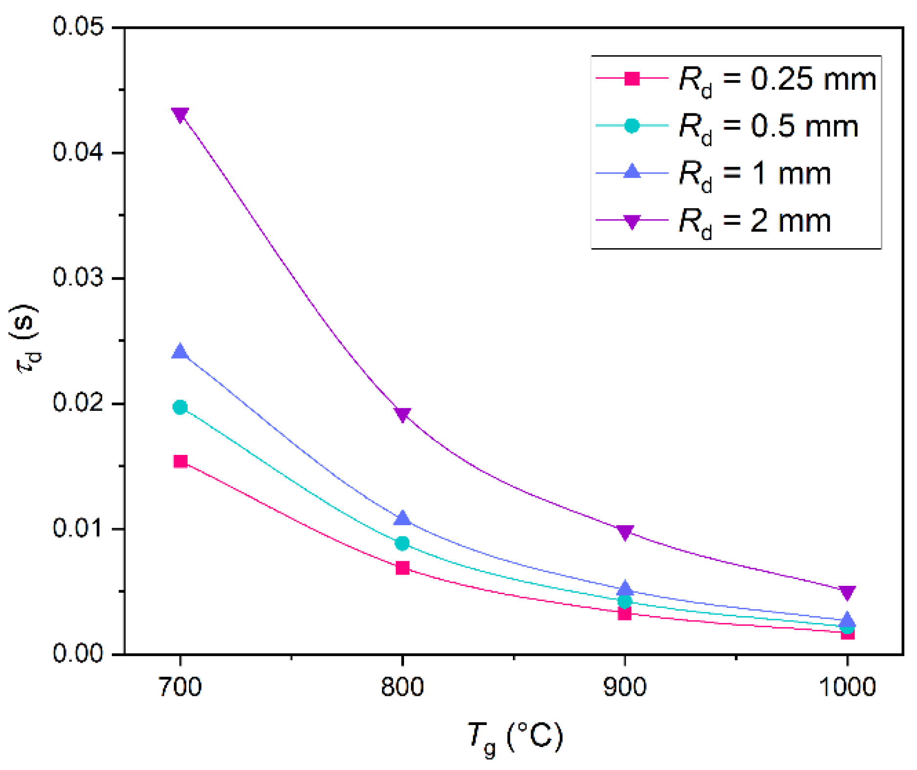
42]. A part of water evaporates and reaches the flame zone. Water also partially drains down through the porous space between hydrate particles. The thickness of the water film governs the heat exchange between the combustion source and the gas hydrate surface. It depends on the ice melting rate, water evaporation rate, convection over the film, as well as drainage rate [42]. With an increase in the water vapor concentration from 0% to 70%, the total methane flow decreased by almost one order of magnitude. Lower vapor content in the gas mixture leads to a considerable increase in the dissociation rate [42]. The propane hydrate combustion time increases at high hydrate saturation and porosity [36], and water formed from the hydrate dissociation plays a key part in this process: it restrains the heat transfer from the flame to the hydrate and prevents the gas from releasing to the combustion zone [36]. The impact of water on the flame characteristics of methane hydrate combustion was studied in [38]. Water vapor released during the hydrate combustion decreases in the flame temperature compared to the combustion of pure methane, and its mechanistic action changes the water response to some elementary reactions. The research findings [38] revealed that the addition of water vapor significantly changed the reaction behavior of some elementary reactions (chemical effect), which led to a reduction in flame temperature. However, the concentration of the intermediate element components decreased as well (physical effect), thus inhibiting the combustion rate [38]. At present, the direct combustion of gas hydrate has been actively studied. Dunn-Rankin [43] proposed the concept of direct energy conversion by on-site combustion of methane hydrates and carbon dioxide sequestration in the deep ocean. A new cylindrical porous burner for burning gas hydrate was proposed in [39] to solve the problem of the appearance of a water film and the self-preservation effect. The proposed burner makes it possible to efficiently use methane hydrate and maintain a stable flame during the combustion process. Using such a counterflow burner, the combustion of methane hydrate can theoretically be categorized as a diffuse methane flame with a large amount of water vapor in the fuel stream. Wu and Chao [44] also proposed a burner for maintaining stable combustion of methane hydrate. It was established that the flame during the combustion of methane hydrate using the proposed burner has an ideal round shape and is similar to a simple symmetrical diffusion flame [44]. The measured gas release rate was about 7.5 mg/s and the average flame temperature of methane hydrate was about 1650 K [44]. The mass fraction of water vapor in the flame of methane hydrate was no more than 80% [44]. Chien and Dunn-Rankin [45] ignited a methane hydrate sample using a piezo igniter and a butane lighter. An ignition device with an open crucible was also used. As a result of the study, the geometry of the flame was obtained from the moment of ignition of the methane hydrate to the moment of its extinguishing. Direct combustion of propane hydrate in a combustion chamber with an electronic igniter was considered in [36]. Chen et al. [36] found that high rates of hydrate dissociation and gas release favor the combustion process. Hydrate-dissociated water plays an important role in this process since the accumulation of water significantly limits both the transfer of heat from the flame to the hydrates and the release of gas into the combustion zone.
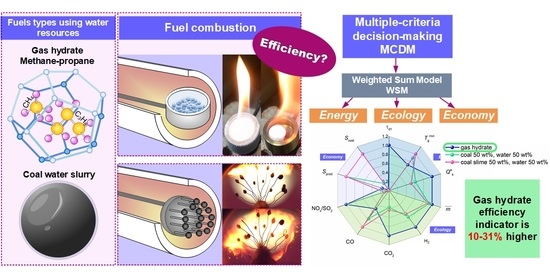
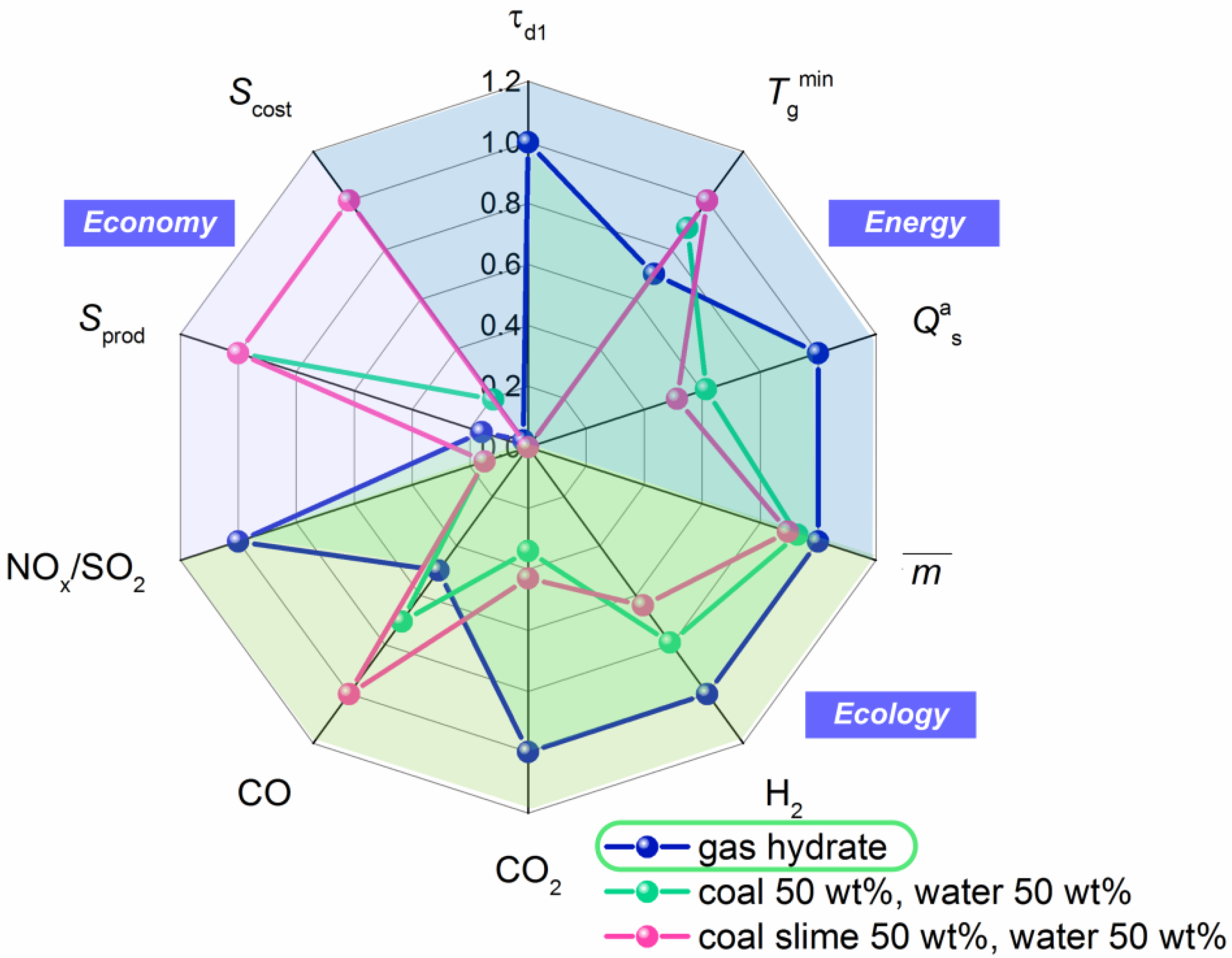
Among the multitude of research fields associated with gas hydrates, the study of their ignition and combustion as high-potential fuels is of special interest. It is advisable to study the impact of water in hydrate on the key combustion stages and the environmental friendliness of the whole process.

1.2. Coal–Water Slurries

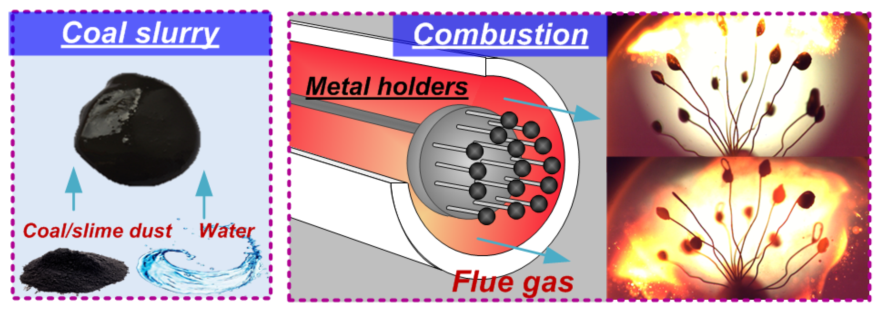
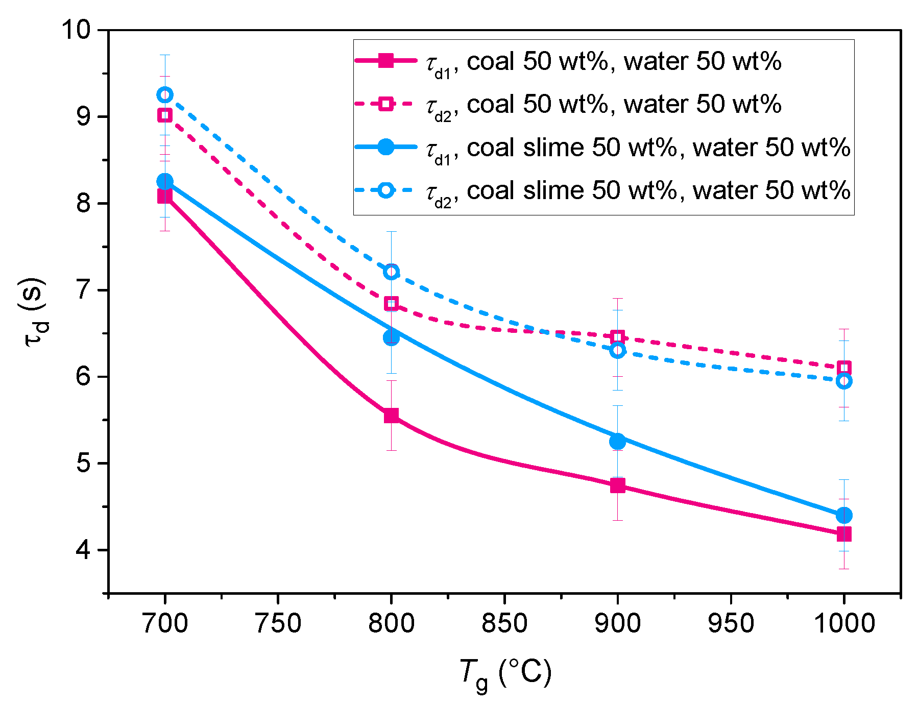
Production of coal–water slurries (CWS) is an alternative way to involve water-based resources in the power-generating sector. These fuels are a mixture of coal components and water with mass concentrations ranging from 35 to 65 wt% [46,47]. Special-purpose additives (biomass [48], used oils [49], oil sludge [50], etc.) in the amount of 5–20 wt% can also be included to increase or reduce certain characteristics, for instance, energy or environmental ones. Such fuels can be produced from a wide range of resources. In particular, coals of different quality (high-rank anthracite or low-rank brown coals) [51,52] and their processing waste (coal slime, middlings, etc.) can be used as the solid component [47,53]. Tap water can serve as the liquid inert constituent. However, a number of research teams used service water [54], liquid industrial waste [55,56], and sewage sludge [57,58] to produce CWS. For instance, the authors in [54] presented experimental research into the impact of water quality on coal–water slurry ignition behavior. The authors used service water obtained from the city power station, tap water, and distilled water. It was experimentally established that CWS based on service water exhibited 8% faster ignition and higher combustion temperatures as compared to fuels based on purified water. This was attributed to the presence of flammable additives and effluents in service water. Their evaporation and combustion accelerated the heating and ignition of coke residue. However, the differences in the ignition delay times between composite fuels based on water of different quality are rather limited: they do not exceed 3% at oxidizer temperatures above 600 °C [54]. Lei et al. [58] studied the co-combustion of sewage sludge and bituminous coal in air. An increase in the proportion of sewage sludge from 0% to 50% shortened the ignition delay time and burnout time of volatiles [58]. Liu et al. [56] presented the experimental research into the combustion of coal–water slurries containing liquid petrochemical waste instead of water. The experimental findings showed that slurries containing liquid petrochemical waste exhibited lower viscosity, faster ignition, higher flame temperature, and lower NOx and SOx emissions compared to conventional coal–water slurries [56]. Thus, depending on the conditions and requirements, service water can be used for CWS production without treatment. This approach is rational as it saves pure water and makes use of service water, which would otherwise be dumped.

1.3. Purpose and Motivation of the Research

The purpose of this research is to compare the prospects of gas hydrates against water-based fuel blends using experiments and mathematical modeling. A comparative analysis can establish the conditions in which water resources should be used to produce fuel hydrates and multi-component blends. As part of the main algorithm employed to compare the efficiency of water in alternative fuels, we calculated the total performance value using multi-criteria decision making (MCDM). Multi-criteria decision analysis covers a large amount of experimental data obtained as part of the research into hydrate and slurry combustion.

2. Combustion of Gas Hydrates

To determine the relative performance indicators [59] of gas hydrate as a fuel blend, it is necessary to take the following parameters into account: economic (fuel cost) [60,61], energetic (minimum ignition temperature, ignition delay times, calorific value, degree of burnout) [62,63], and environmental (anthropogenic gaseous emissions) [64,65,66]. The ignition and combustion of methane–propane hydrate (the fraction of methane was 0.6, and the fraction of propane was 0.4) was studied experimentally and theoretically to establish the characteristics listed above. Gas hydrate was a powder with a particle (granule) size Rd = 0.25 mm.
The hydrate ignition behavior was experimentally studied under the conditions of radiative heating of gas hydrate powder according to the method described in detail in [67]. The experimental setup for studying the ignition of gas hydrates is schematically represented in Figure 1. The main element of the setup was a muffle furnace heated to high temperatures. The gas hydrate samples were ignited in a high-temperature motionless air medium generated in a hollow ceramic tube of an R 50/250/13 muffle furnace (Nabertherm GmbH, Lilienthal, Germany). The air temperature in the furnace was varied from 700 to 1000 °C and monitored using an in-built type S thermocouple. The furnace was heated to a given temperature in each series of 5 experiments. Gas hydrate with an initial temperature of −70 °C was weighed on an AJH-620CE balance (Shinko Denshi Co., Ltd., Tokyo, Japan) with an accuracy of ±0.001 g and placed into a V-shaped fine metal mesh (reservoir). Using a positioning mechanism, we introduced the gas hydrate reservoir into a hollow tube of the heated furnace. The processes taking place during the induction period were recorded by a high-speed video camera. The resulting video recordings were analyzed using the Tema Automotive software. The concentration of gases released from the combustion was measured using a Test 1 gas analyzer (Bonair-VT, Novosibirsk, Russia). The gas analyzer probe was introduced into the central combustion zone (muffle furnace). The gas released during the combustion was supplied through the probe and the sampling hose to the gas analyzer sensors. The resulting gas concentrations were monitored using the specialized Test software. The average concentrations were calculated using the trapezoidal rule. The calculation method is described in more detail in [68].
As a result of the experimental research, we determined the ignition delay times (τd1), the minimum temperatures required for the gas hydrate ignition (Tgmin), and the degree of fuel burnout. We also detected the main components of the gas mixture from the gas hydrate combustion: H2, CO2, CO, NOx, SO2. Using the experimental findings, we developed a physical and mathematical model simulating the ignition of gas hydrates by radiative heating. According to the problem statement, cold gas hydrate powder was introduced into the motionless air of a muffle furnace heated to 700–1000 °C. When the powder was heated by radiative heat supply, its surface temperature reached the gas hydrate dissociation point. After it decomposed into gas and ice, the ice component started melting. A melting front was formed with a boundary moving inward in the gas hydrate sample. When the vaporization conditions were reached, the water film started evaporating from the sample surface. Gas–vapor mixture was formed around the hydrate particle. When the air temperature and the concentration of the mixture was sufficient for ignition, the gas hydrate started burning. The solution domain for heat transfer under the conditions of radiative heating was described by a system of transient partial differential equations with the corresponding boundary conditions similar to those used in [69]. The following constants were used as source data in the numerical simulation: thermal conductivity of gas hydrate λg = 1.33 W/(m·K); specific heat capacity of gas hydrate Cg = 2200 J/(kg·K); density of gas hydrate ρg = 909 kg/m3; activation energy of the fuel vapor oxidation reaction Ea = 145 × 103 J/mol; pre-exponential factor of the fuel vapor oxidation reaction k0 = 7.4 × 10⁸ s1; mass hydrate dissociation rate Wg = 0.01 kg/(m2∙s); water evaporation heat Qevap = 2.2 × 10⁶ J/kg; dissociation heat of gas hydrate Qg = 108 × 103 J/kg; ice melting heat Qmelt = 3.4 × 10⁵ J/kg. The system of equations was solved using the finite difference method. The time increment was 10−6 s. The solution was carried out in MATLAB [69]. As a result of the theoretical study, using the newly developed physical and mathematical models, we determined the ignition delay times of gas hydrate and the minimum temperature required for the ignition. Table 1 gives the minimum temperatures required for the ignition of methane–propane hydrate obtained experimentally and theoretically.
Figure 2 presents the double gas hydrate ignition delay times under radiative heating obtained experimentally and theoretically with varying heating source temperature from 700 to 1000 °C.
Figure 2 shows that the ignition delay times of gas hydrates go down from 0.014 s to 0.001 s with an increase in the heating source temperature. The ignition delay times obtained experimentally and theoretically differ on average by up to 15%. With a heating source temperature over 900 °C, the ignition delay times are one-third of those at 800 °C. At high temperatures of the heating source (over 900 °C), higher gas hydrate dissociation rate (decomposition into gas and water) sharply accelerates the exothermic reaction, thus reducing the ignition delay times. A decrease in the ignition delay times by several orders of magnitude suppresses the formation of water vapor around the fuel sample. As mentioned earlier, water vapor significantly changes the reaction behavior of some elementary reactions (chemical effect), which leads to a reduction in flame temperature and slows down combustion.
As a result of modeling, we obtained the curves of the gas hydrate ignition delay time against the heating source temperature Tg with varying hydrate particle size Rd from 0.25 mm to 2 mm (Figure 3). The figure shows that the ignition delay times increase with an increase in the hydrate particle radius (in particular, they triple with an increase in the particle radius with the furnace temperature remaining constant). The ignition delay times used in the calculations in Section 4 correspond to the gas hydrate particle size Rd = 2 mm, which equals the size of slurry fuel droplets used in Section 3.
It was experimentally established that the degree of the fuel sample burnout (m) at a gas temperature ranging from 700 to 1000 °C is 100%. Due to the component composition of gas hydrates, their combustion is notable for a high concentration of water vapor in the flame, which has a significant impact on elementary chemical reactions and on the combustion kinetics in general [38]. To reduce the harmful emissions while maintaining the energetic, economic, and other indicators of the processes, it is necessary to study the impact of temperature on the concentrations of anthropogenic emissions. The main components of the gas–vapor mixture that generally fall under the radar are hydrogen (H2), carbon monoxide (CO), nitrogen oxide (NOx), sulfur oxide (SO2), and carbon dioxide (CO2) [68,71,72]. Greenhouse (CO2) and anthropogenic (NOx and SO2) gases have an especially detrimental effect on the biosphere, human health, and climate [73,74,75]. Table 2 gives the average concentrations of the gaseous products of the methane–propane hydrate combustion—in particular, anthropogenic and greenhouse gases—emitted at different heating source temperatures. Clearly, the heating source temperature directly influences the emission of all the gases detected in the experiments. An increase in the heating source temperature from 700 to 1000 °C gives an up to 2.5-times increase in the concentrations of the gaseous products of hydrate combustion. The main types of nitrogen oxides from the combustion of gas hydrates are prompt and thermal NOx. The combustion rate and flame temperature increases with an increase in the heating source temperature, which leads to higher NOx concentrations in the gas mixture emitted from the combustion. Increasing the gas temperature with an increment of 100 °C provides a 56% increase in the nitrogen oxide concentration.
Gas hydrates are burned in a steam-air medium (because of ice shell melting and water evaporation), so carbon monoxide is partially spent in the water gas shift reaction. As a result, additional H2 and CO2 are formed, and their concentration doubles with an increase in the furnace temperature in the range of 700–1000 °C. Similarly to hydrogen, the concentrations of carbon monoxide (CO) increase noticeably at a furnace temperature above 900 °C. The concentrations of carbon monoxide increase from 13% to 75% in the temperature range of 700 °C to 1000 °C. Gas hydrate combustion does not emit sulfur oxides at all, which confirms the environmental benefit of using hydrates instead of conventional fuels.

3. Combustion of Slurry Fuels

The ignition and combustion behavior of slurry fuels was analyzed on the basis of experimental data. We chose the following parameters to characterize the slurry droplet ignition and combustion: gas-phase ignition delay (τd1); heterogeneous ignition delay (τd2); minimum ignition temperature (Tgmin); degree of burnout ( m ¯ ); concentration of the main gases (CO2, CO, H2, NOx, SO2). We also calculated the calorific value (Qas) of slurry fuels with regard to the component characteristics and mass concentration. These characteristics are the key parameters describing the entire process flow including ignition (gas-phase ignition delay times and minimum ignition temperatures), stable combustion (heterogeneous ignition delay times, composition and concentration of combustion products), smoldering and self-extinguishing (degree of burnout). The measurement of these parameters will make it possible to fully evaluate the efficiency of combustion, compare different fuel types, and identify the key strengths and weaknesses of the combustion scheme of choice, etc. In addition, these parameters are especially typical of research into ignition and combustion mechanisms of conventional and composite fuels [76,77,78,79]. For instance, Nguyen et al. [77] studied the ignition behavior of hydrocarbon fuels produced from carbonized biomass. They measured the ignition times and temperatures for solid fuels and slurries on their basis by using radiative heating. The research findings demonstrated that hydrochar slurry derived from biomass are easy to ignite (ignition delay times varied from 0.2 to 2.38 s) at relatively low temperatures (89 to 103 °C) [77]. Zhu et al. [78] recorded the ignition delay times and burnout rate of single droplets of biochar water slurry produced by biomass pyrolysis. They showed that the ignition delays and burnout times increased with an increase in the initial droplet size. It was also established that droplets with over 60% of water were notable for higher combustion rate after water evaporation due to the enhanced oxygen diffusion to the outer droplet layers [78]. Lei et al. [58] carried out the oxy-fuel co-combustion of sewage sludge and bituminous coal. An increase in the proportion of sewage sludge from 0% to 50% led to a decrease in the volatiles’ ignition delay time and particle burnout time. The average flame temperature also increased by 66.8 °C. Gaber et al. [46] found that it is important to use fine particles of pyrolytic carbon black to provide the full burnout of a slurry. A high proportion of water (65–75%) in the blends contributed to a decrease in NOx and CO emission to a fraction of the initial level with quite a limited reduction in the combustion temperature. Zhang et al. [80] focused on the ignition and combustion of fuel blends based on anthracite and sawmill waste. The experimental research established that fast volatiles’ emission from the combustion of wood components accelerated the anthracite ignition and carbon burnout; at the same time, the temperature and time of complete combustion decreased. The variation dynamics of SO2 and NO concentrations during the combustion were analyzed as well. The SO2 emissions became one tenth of the original value with an increase in the content of wood components from 0 to 50%. The NO emission decreased negligibly. The literature review has shown that the entire array of characteristics (ignition delays and temperatures, degree of combustion, and concentration of the main anthropogenic emissions) are not usually measured within one study. Therefore, it is important to cover all the main water-based fuel combustion parameters and characteristics in the present research. The resulting values will be further used to calculate the relative parameters showing the strengths and weaknesses of slurry fuels compared to gas hydrates.
The integral ignition and combustion characteristics of slurry fuels were determined using a setup, similar to the one presented in Figure 1. A tubular muffle furnace was used to provide a high-temperature medium. The temperature variation range was 700–1000 °C. All the typical ignition and combustion stages of water-containing fuel slurries take place in this temperature range. They are accompanied by active vaporization, which allowed us to measure the concentrations of the gas mixture components accurately enough. After heating the furnace, we placed a holder with the fuel into the furnace with the help of the positioning mechanism. The key difference of this measurement technique from the one presented in Section 2 is the introduction of fuel into the combustion chamber. Here we used a metal structure with 15 holders with fuel droplets, 2 mm in diameter, suspended on those holders. The fuel mass was 0.2 g. The snapshot showing the slurry supply to the combustion chamber is presented in Figure 4.
After the fuel introduction, the orifice was sealed by a thick layer of a heat insulation material. A modular probe of the gas analyzer was inserted into a similar-sized orifice on the opposite side. This orifice was also sealed. After the end of each experiment, the gas channels and the space of the muffle furnace were aired to remove the remains of the gases. For all the measured parameters, regardless of their type, we removed the outliers, determined the variation coefficients, and calculated the confidence interval with a confidence probability of 0.95. The average values in a series of experiments were used to calculate the efficiency indicators. A more detailed description of the setup elements, errors, measurement techniques, and data processing can be found in [81,82].
The coal–water slurry used in the experiments was based on coking bituminous coal from Berezovskoe deposit (Kemerovo region, Russia) and coal slime—a typical processing waste of the same-rank coal. This waste is generated at coal washing plants in the course of flotation. The mean particle size of coal slime ranges from 80 to 100 µm. The size of coal particles in the experiments was also 80–100 µm. Table 3 presents the results of elemental and proximate analysis of coal and coal slime.
We used these components to prepare two slurries with mass fractions of coal particles and water maintained at 50 wt%: 50 wt% of coal and 50 wt% of water; 50 wt% of coal slime and 50 wt% of water. The blends were based on tap water.
Table 4 presents the minimum ignition temperatures and calorific values of the two slurries used in the experiments. The parameter Tgmin reflects the minimum temperature of the air-vapor medium (temperature in the combustion chamber) providing the stable ignition and subsequent heterogeneous combustion of the coal char. According to the data obtained (Table 4), the slurry based on coal slime ignited at lower temperatures. The difference in the threshold ignition temperatures for the two slurries under study was 50 °C. It can be attributed to the special aspects of liquid evaporation from the surface of slurry fuel droplets. The slurry based on coal slime was denser and more viscous due to the content of surfactants used in coal enrichment. Water evaporated from its surface faster than from the surface of the coal-based slurry. Higher vapor concentration in the close vicinity of slurry droplets based on coal slime enhanced its heating and reactivity. The calorific value of the coal slime-based slurry is 16% lower than that of the coal-based fuel because the ash content of coal slime is 1.8 times higher (Table 3). As a result, the content of combustible components to a dry ash-free state is lower in coal slime than in coal.
Figure 5 presents the gas-phase ignition delay time (solid line) and heterogeneous ignition delay time (dotted line) of the slurry fuels. The gas-phase ignition of the coal-based slurry was found to occur with a 20% shorter delay. This pattern is especially noticeable in the temperature range from 750 to 850 °C. In this temperature range, the ignition of slurries based on coal slime took 0.75–1.14 s longer. This is because bituminous coal contains more volatile substances (Table 3), whose release intensifies the gas-phase ignition stage. The gas-phase combustion of volatile substances contributes to a significant increase in the char temperature and, hence, shortens its heterogeneous ignition delay. According to the data obtained, the heterogeneous ignition of bituminous coal in the slurry also occurred after a shorter delay in the temperature range of 700–900 °C as compared to coal slime. However, the difference in the values of τd2 for the two blends is much smaller than with τd1. This is also attributed to the content of volatiles in the coal components and the duration of their combustion. As coal contains more volatiles, their burnout time is longer, which levels out the difference in the heterogeneous ignition delay times. At a peak temperature (1000 °C), the gas-phase and heterogeneous ignition delays of the two fuels under study are practically the same. This suggests that the thermal effect dominates the high-temperature zone, and fuel properties have a much smaller effect on the ignition behavior. The research has also revealed that the gas-phase ignition delay times decreased considerably with a temperature increase. However, higher temperature did not affect the heterogeneous ignition delays quite as much. A temperature increase leads to an increase in the concentration of flammable gases around the fuel particle due to a higher decomposition rate (the gas release is enhanced). Therefore, the burnout time of the gas mixture is longer due to its larger amount. In this case, the fuel’s heterogeneous ignition begins somewhat later. Thus, the interval between the gas-phase and heterogeneous ignition becomes longer with a temperature increase.
Figure 6 shows the relative fuel burnout indicator versus the temperature in the combustion chamber, which was given by
m ¯ = m 0 m 1 m 0 · 100 %
where m0 is the initial mass of the sample, and m1 is the mass of the unburnt char.
In line with Equation (1), the greater the value of m ¯ , the higher the degree of fuel burnout. Figure 6 shows a 3–10% increase in the burnout degree with a rise in temperature. Comparing the two coal components, we can see that the slurry based on bituminous coal burned out better than coal slime. The degree of burnout is up to 7% higher for coal than for coal slime due to the high ash content of the latter (Table 3). It is noteworthy, however, that the degree of burnout ranging from 82% to 94% depending on the temperature in the combustion chamber is overall not bad for slurries, especially for a waste-derived one. This can serve as a rationale for the development of combustion technologies of fuel slurries based on coal and coal slime in the form of mists and sprays due to the opportunity to reduce the losses of incomplete combustion.
Environmental performance is among the most significant aspects of fuel combustion. In particular, here we measured the concentrations of the main flue gas components emitted from the combustion of the two slurries. The measurement results are presented in Table 5. We have identified a number of dependences typical of slurry combustion. First, higher temperature in the combustion chamber led to a marked increase in the concentrations of all the gases under study but CO. The concentrations increased by 2.52–3.71 times for H2, by 2.03–2.07 times for CO2, by 1.79–2.41 times for NOx, and by 9–12 times for SO2 with a temperature increase from 700 to 1000 °C. Increased concentrations of these gases indicates the intensified oxidation and decomposition reactions, whose rates depend directly on the ambient temperature. Higher CO2 emissions with a simultaneous decrease in CO indicates an increase in the burnout degree of the coal component: more fuel carbon participates in combustion, hence lower carbon loss. Another important aspect is that the component-specific findings correlate well with the content of carbon, sulfur, and nitrogen in coal and coal slime. For instance, a difference in the NOx concentration is recorded, which is 9–17% higher for coal slurry than for coal slime at temperatures over 800 °C. This effect is associated with a different content of fuel nitrogen (Table 3), which is 5% higher for coal (with regard to the ash content of the components). Additionally, coal slime contains 1.8 times more ash. Thus, the proportion of the combustible part of the fuel, which contains most of the fuel nitrogen, is much lower. As a result, the NOx concentrations are lower from the decomposition and oxidation of burning coal slime. In addition, coal has a higher calorific value, so its combustion produces more thermal energy. The temperature in the combustion zone increases, thus intensifying the nitrogen oxide emission. The reasons are similar for the differences in the concentrations of CO2 and CO, which are 26–33% and 36–72% higher for the coal-based slurry. As for SO2 emissions, higher concentrations are recorded from the combustion of coal slime, which also correlates with the content of primary sulfur in the fuel (Table 3). Coal slime is an enrichment waste produced during high-rank coal washing, which also removes sulfur from coal. Logically, the content of mineral and organic sulfur in coal processing wastes will be much higher, which affects the emissions of this gas.

4. Relative Efficiency Indicators of Fuel Combustion

It is quite difficult to specify all the decision making criteria used when choosing between alternatives: in particular, when choosing an energy source in the power-generating sector. Ranking the criteria for an objective and transparent evaluation of different options is an important objective. This is what makes multi-criteria decision making methods (MCDM) appealing. These methods provide the comparison of several options as part of a preliminary analysis, which outlines the most preferable and inappropriate decisions. They also compare the options when there are several, sometimes contradictory, criteria. Finally, MCDM can help find a compromise in a scenario where different stakeholders have conflicting goals or values. A set of criteria for analysis serves as the input data for such methods. The criteria based on the target goals can be applied to all the alternatives in order to differentiate between them. There are various methods within MCDM that govern the weight assignment to each criterion and different ways of integrating the evaluations into a total performance value using criteria for each option. For example, evaluations can be integrated into a Weighted Sum Model (WSM) or Weighted Product Model (WPM) [83], using the Analytic Hierarchy Process (AHP) [84] and Preference Ranking Organization Method for Enrichment Evaluation (PROMETHEE) [84], as well as the Technique for Order Preference by Similarity to Ideal Solution (TOPSIS) [85], etc. Despite the abundance of methods, the main idea remains the same for most of them: alternatives are ranked using a set of normalized (dimensionless) characteristics and compared with the best alternative or ideal solution [86]. Weighted Sum Model (WSM) for one-dimensional problems is the simplest and most popular method [84,86,87]. In this research, we also decided to use this method as an initial evaluation of the efficiency of using water resources as part of gas hydrates or slurry fuels. According to the WSM algorithm, all the criteria with the weights assigned depending on their importance or priority are normalized to the best value. As a result, all the criteria expressed in different units are normalized and converted to dimensionless values. The values of the normalized criteria are within the interval of 0–1. The summarizing fuel combustion efficiency indicator is written as
A n = γ j · X i j
where γj is the weight for each criterion, and Xij is the normalized value of a criterion.
Assigning weights can often be a challenge since the solution severely depends on the weights chosen. When the problem is country-, region- or enterprise-specific, it is rational to set priorities, while equal weights are mostly used when there is no detailed information on the importance of a certain criterion. In this case, the total weight (100%) is distributed evenly among all the criteria to obtain equal weights. This weight distribution method is especially typical of simple MCDA systems and used for initial generalizing analysis. That is why we used equal weights for this research. The fuel with the highest weighted sum is considered the best in terms of the chosen criteria. Table 6 presents the absolute and normalized values of fuel evaluation criteria obtained in this research. For a meaningful comparison, all the values were normalized: the calorific value, gas concentrations, degree of burnout, and cost were divided by the mass, and the ignition delay times were divided by the fuel droplet size. In addition, since no heterogeneous combustion was recorded for gas hydrate (unlike for slurries), the parameter reflecting this process (τd2) was removed from further calculation of An.
Table 7 gives the total combustion efficiency indicators for the three fuel types calculated using Equation (2).
The comparison of fuel combustion characteristics has shown that gas hydrates yield the maximum total performance value. The calculated value of An for gas hydrates is 10–31% higher than that for slurry fuels (Table 7). This result can be attributed to the dominance of gas hydrates in terms of energy-related characteristics (Figure 7).
The ignition delay is hundreds and thousands of times shorter for hydrates than for slurries (Table 6). At the same time, the amount of thermal energy released from the combustion of one kilogram of fuel is somewhat higher in the case of hydrate. Environmentally, gas hydrates are also clearly superior. The concentrations of the main harmful emissions (CO2 and NOx) released from the combustion of slurries are 42–68% and 76–83% higher, respectively. Another crucial factor is that sulfur oxides are not emitted during the combustion of gas hydrates, which is a major environmental benefit of this fuel. In terms of the regulatory documents (Table 8), the NOx and SO2 concentrations detected during the slurry combustion at 700–900 °C also fall within the allowable range. The maximum allowable concentrations presented in Table 8 imply that the flue gas has passed through all the treatment stages enforced in actual power-generating facilities. In the experiments, however, the concentrations were measured in the immediate vicinity of the burning fuel. Therefore, if we assume that the flue gas emitted from the combustion of slurry fuels will be exposed to the standard treatment procedure, the NOx and SO2 concentrations will comply with European and Asian standards for the purity of flue gas (Table 8).
Figure 7 shows that gas hydrates are far inferior to slurry fuels in terms of economic indicators. The cost of the industrial development of gas hydrate deposits is estimated as much higher than other known ways of recovery suitable for conventional energy resources. Low temperatures, high pressures, and high-salinity reservoir waters complicate the exploitation of arctic deposits and, hence, involve high procurement costs. Transportation of gas hydrates can be identified as a separate expenditure item. It requires large transportation reservoirs maintaining low temperatures (at least −70 °C) and elevated pressure (over 4 MPa). These economic issues are among the key barriers to the development of this technology.
Additionally, the limiting factors for the use of gas hydrates are the existing methods of fuel supply to the furnace and bed combustion technologies. The hydrate powder feeding is accompanied by uneven filling, which leads to supercooling of the combustion chamber walls and an instant decrease in the furnace temperature. It is necessary to ensure the uniformity of the powder layer at all technological stages: fuel supply, residence in the combustion chamber, and ignition process. Moreover, when the temperature rises, self-preservation of the gas hydrate takes place, which is a problem for its direct combustion. Self-preservation may occur throughout the entire reaction period and leads to the cessation of the release of combustible gas to the surface and the flame failure in the combustion chamber. Several concepts for the use of gas hydrates as fuel can be distinguished, excluding the technological difficulties described above. There are several concepts for the use of gas hydrates as a fuel in combustion chambers, excluding the listed technological difficulties. For example, gas hydrate powder can be fed into the reactor using an automated conveyor that levels the powder bed to a predetermined level. The gas hydrate dissociation occurs in the reactor at constant temperature and pressure. The dissociated gas through the pipes will be fed into the furnace or combustion chamber. The second concept is the direct supply of gas hydrate to the combustion chamber without a preliminary dissociation reactor. To prevent cooling of the furnace walls due to the large flow of gas hydrate, it is necessary to consider the method of fuel powder supply. This can also be realized through an automated conveyor belt, which will carry a uniform layer of powder through the combustion chamber. It is necessary to calculate the total time for the conveyor belt to pass through the entire area of the chamber so that the gas hydrate powder has time to completely dissociate and release all the gas. The speed of the conveyor belt must be adjusted so that the volume of combustible gas is sufficient to ensure continuous combustion. The third concept is to use the similarity of Raschig rings. In this case, the hydrated powder is sprayed from the top of the combustion chamber through the rings. Due to the mobility of the rings, it is possible to provide vibration, which contributes to the uniformity of the powder layer at all stages (rings) of the combustion chamber and further ignition of the released gas. The effect of self-preservation of the gas hydrate can be avoided by constant mechanical friction of the powder particles. This can be ensured by the use of specialized gratings, on the surface of which gas hydrate particles will be supplied. Due to the constant movement and impacts of the gratings between themselves, the fuel particles will be subjected to mechanical displacement. Friction will occur between the powder particles, which will prevent cooling and self-preservation.
Being a fraction of the cost of conventional energy resources, coal slime-based blends turned out to be the most economically appealing. Low cost and large production volumes of coal waste (over one billion tons annually) are major benefits of this technology. Moreover, coal enrichment technology implies that the by-product of coal processing contains a considerable amount of water (30 to 60 wt%) in addition to coal particles. Hence, this waste type can be used without adding extra water.

5. Conclusions

The ignition and combustion behavior of promising alternative fuels based on water and a combustible component was studied experimentally and theoretically. We used a methane–propane hydrate and coal–water slurries based on coal and coal slime. The minimum temperature required for the ignition of the methane–propane hydrate was found to be 570 °C. The gas hydrate ignition delay times go down from 0.043 s to 0.005 s with an increase in the temperature of the radiative heating source. The environmental analysis has shown that the concentrations of gaseous products released from the hydrate combustion increase by 2.5 times with a temperature increase from 700 to 1000 °C. The main environmental advantage of gas hydrates over conventional fuels consists in zero sulfur oxide emission. The slurry based on coal slime was found to ignite at lower temperatures. The difference in the threshold ignition temperatures for the two slurries under study was 50 °C. At the same time, the gas-phase ignition delay of the coal-based slurry was up to 20% shorter. The relative burnout indicator of the slurry based on bituminous coal turned out to be 2–6% higher, which makes little difference and is attributed to the high ash content of coal slime. The environmental combustion indicators of the two slurries fell within quite a narrow concentration range. However, the combustion of the coal-based slurry resulted in 26–33%, 36–72%, and 9–17% higher emissions of CO2, CO, and NOx, respectively. As for SO2 concentrations, higher emissions were recorded from the combustion of coal slime, which also correlates with the content of primary sulfur in the fuel. Gas hydrate had the highest total performance value based on 10 separate components from three categories. The calculated value of An for hydrates was 10–31% higher than that for slurry fuels. The values of absolute, relative, and integral indicators obtained for slurries and hydrates can be used in feasibility studies of alternative ways to involve water resources in the power industry.

Author Contributions

Conceptualization, P.S.; data curation, P.S.; funding acquisition, P.S.; investigation, G.N., D.A. and O.G.; writing—original draft, G.N., D.R. and O.G.; writing—review and editing, P.S. All authors have read and agreed to the published version of the manuscript.

Funding

The study of gas hydrates combustion was supported by a grant of the Ministry of Science and Higher Education of Russia, Agreement No 075-15-2020-806 (Contract No 13.1902.21.0014). The researches of ignition and combustion of slurry fuels were supported by a grant of the President of the Russian Federation, project No MD–1616.2022.4.

Conflicts of Interest

The authors declare no conflict of interest.

References

  1. Guo, Z.; Yuan, Y.; Jiang, M.; Liu, J.; Wang, X.; Wang, B. Sensitivity and Resolution of Controlled-Source Electromagnetic Method for Gas Hydrate Stable Zone. Energies 2021, 14, 8318. [Google Scholar] [CrossRef]
  2. Li, X.; Wang, C.; Li, Q.; Fan, Q.; Chen, G.; Sun, C. Study on the growth kinetics and morphology of methane hydrate film in a porous glass microfluidic device. Energies 2021, 14, 6814. [Google Scholar] [CrossRef]
  3. Cai, W.; Huang, X.; Lu, H. Instrumental Methods for Cage Occupancy Estimation of Gas Hydrate. Energies 2022, 15, 485. [Google Scholar] [CrossRef]
  4. Li, X.S.; Xu, C.G.; Zhang, Y.; Ruan, X.K.; Li, G.; Wang, Y. Investigation into gas production from natural gas hydrate: A review. Appl. Energy 2016, 172, 286–322. [Google Scholar] [CrossRef] [Green Version]
  5. Gambelli, A.M.; Filipponi, M.; Rossi, F. How methane release may affect carbon dioxide storage during replacement processes in natural gas hydrate reservoirs. J. Pet. Sci. Eng. 2021, 205, 108895. [Google Scholar] [CrossRef]
  6. Hiruta, A.; Matsumoto, R. Geochemical comparison of ikaite and methane-derived authigenic carbonates recovered from Echigo Bank in the Sea of Japan. Mar. Geol. 2022, 443, 106672. [Google Scholar] [CrossRef]
  7. Misyura, S.Y.; Donskoy, I.G. Dissociation kinetics of methane hydrate and CO2 hydrate for different granular composition. Fuel 2020, 262, 116614. [Google Scholar] [CrossRef]
  8. Chen, Y.; Ding, J.; Zhang, H.; Tang, Q.; Zhou, X.; Liu, X. Multibeam water column data research in the Taixinan Basin: Implications for the potential occurrence of natural gas hydrate. Acta Oceanol. Sin. 2019, 38, 129–133. [Google Scholar] [CrossRef]
  9. Ghaani, M.R.; Young, J.M.; Nandi, P.K.; Dandare, S.; Allen, C.C.R.; English, N.J. Microbial stabilisation and kinetic enhancement of marine methane hydrates in both deionised- and sea-water. Petroleum 2021, 7, 402–406. [Google Scholar] [CrossRef]
  10. Ketzer, M.; Praeg, D.; Rodrigues, L.F.; Augustin, A.; Pivel, M.A.G.; Rahmati-Abkenar, M.; Miller, D.J.; Viana, A.R.; Cupertino, J.A. Gas hydrate dissociation linked to contemporary ocean warming in the southern hemisphere. Nat. Commun. 2020, 11, 3788. [Google Scholar] [CrossRef] [PubMed]
  11. Malakhova, V.; Golubeva, E. Model Study of the Effects of Climate Change on the Methane Emissions on the Arctic Shelves. Atmosphere 2022, 13, 274. [Google Scholar] [CrossRef]
  12. Duan, S.; Hölz, S.; Dannowski, A.; Schwalenberg, K.; Jegen, M. Study on gas hydrate targets in the Danube Paleo-Delta with a dual polarization controlled-source electromagnetic system. Mar. Pet. Geol. 2021, 134, 105330. [Google Scholar] [CrossRef]
  13. Lee, M.W.; Dillon, W.P. Amplitude blanking related to the pore-filling of gas hydrate in sediments. Mar. Geophys. Res. 2001, 22, 101–109. [Google Scholar] [CrossRef]
  14. Liu, J.; Guo, T.; Wang, B.; Guo, Z. Review of marine electromagnetic methods for hydrocarbon exploration. Geophys. Prospect. Pet. 2021, 60, 527–538. [Google Scholar] [CrossRef]
  15. Liu, X.; Xing, L.; Qin, Z.; Liu, H. The Sensitive Properties of Hydrate Reservoirs Based on Seismic Stereoscopic Detection Technology. Acta Geol. Sin. 2020, 94, 530–544. [Google Scholar] [CrossRef]
  16. Wu, Q.; Huang, Y. Indications of sandstone-type uranium mineralization from 3D seismic data: A case study of the Qiharigetu deposit, Erenhot Basin, China. J. Pet. Explor. Prod. 2021, 11, 1069–1080. [Google Scholar] [CrossRef]
  17. Geranutti, B.; Pohl, M.; Karimi, S.; Prasad, M.; Zerpa, L.E. Geophysical measurements for detection of hydrate formation in coreflooding experiments with undersaturated oil and seawater injection. In SEG Technical Program Expanded Abstracts 2020; Society of Exploration Geophysicists: Houston, TX, USA, 2020; pp. 2555–2559. [Google Scholar] [CrossRef]
  18. Wang, Y.; Gao, D. Study on the marine environment limiting conditions of deepwater drilling for natural gas hydrate. Appl. Energy 2022, 312, 118802. [Google Scholar] [CrossRef]
  19. Sun, W.; Pei, J.; Wei, N.; Zhao, J.; Xue, J.; Zhou, S.; Zhang, L.; Kvamme, B.; Li, Q.; Li, H.; et al. Sensitivity analysis of reservoir risk in marine gas hydrate drilling. Petroleum 2021, 7, 427–438. [Google Scholar] [CrossRef]
  20. Misyura, S.Y. Comparing the dissociation kinetics of various gas hydrates during combustion: Assessment of key factors to improve combustion efficiency. Appl. Energy 2020, 270, 115042. [Google Scholar] [CrossRef]
  21. Yang, M.; Dong, S.; Zhao, J.; Zheng, J.N.; Liu, Z.; Song, Y. Ice behaviors and heat transfer characteristics during the isothermal production process of methane hydrate reservoirs by depressurization. Energy 2021, 232, 121030. [Google Scholar] [CrossRef]
  22. Li, G.; Li, B.; Li, X.S.; Zhang, Y.; Wang, Y. Experimental and numerical studies on gas production from methane hydrate in porous media by depressurization in pilot-scale hydrate simulator. Energy Fuels 2012, 26, 6300–6310. [Google Scholar] [CrossRef]
  23. Schicks, J.M.; Spangenberg, E.; Giese, R.; MLuzi-Helbin, M.; Priegnitz, M.; Beeskow-Strauch, B. A counter-current heat-exchange reactor for the thermal stimulation of hydrate-bearing sediments. Energies 2013, 6, 3002–3016. [Google Scholar] [CrossRef]
  24. Feng, J.C.; Wang, Y.; Li, X.S.; Li, G.; Chen, Z.Y. Production behaviors and heat transfer characteristics of methane hydrate dissociation by depressurization in conjunction with warm water stimulation with dual horizontal wells. Energy 2015, 79, 315–324. [Google Scholar] [CrossRef]
  25. Li, L.; Li, X.; Wang, Y.; Qin, C.; Li, B.; Luo, Y.; Feng, J. Investigating the interaction effects between reservoir deformation and hydrate dissociation in hydrate-bearing sediment by depressurization method. Energies 2021, 14, 548. [Google Scholar] [CrossRef]
  26. Yuan, Q.; Sun, C.-Y.; Yang, X.; Ma, P.-C.; Ma, Z.-W.; Li, Q.-P.; Chen, G.-J. Gas Production from Methane-Hydrate-Bearing Sands by Ethylene Glycol Injection Using a Three-Dimensional Reactor. Energy Fuels 2011, 25, 3108–3115. [Google Scholar] [CrossRef]
  27. Chen, L.; Feng, Y.; Okajima, J.; Komiya, A.; Maruyama, S. Production behavior and numerical analysis for 2017 methane hydrate extraction test of Shenhu, South China Sea. J. Nat. Gas Sci. Eng. 2018, 53, 55–66. [Google Scholar] [CrossRef]
  28. Liu, H.; Li, H.; Yao, D.; Guo, P.; Wen, L. The research on the natural gas hydrate dissociation kinetic from hydrate-sediments/seawater slurries. Chem. Eng. J. 2022, 435, 135127. [Google Scholar] [CrossRef]
  29. Kuhs, W.F.; Genov, G.; Staykova, D.K.; Hansen, T. Ice perfection and onset of anomalous preservation of gas hydrates. Phys. Chem. Chem. Phys. 2004, 6, 4917–4920. [Google Scholar] [CrossRef]
  30. Misyura, S.Y.; Donskoy, I.G. Dissociation of gas hydrate for a single particle and for a thick layer of particles: The effect of self-preservation on the dissociation kinetics of the gas hydrate layer. Fuel 2022, 314, 122759. [Google Scholar] [CrossRef]
  31. Stern, L.A.; Circone, S.; Kirby, S.H.; Durham, W.B. Temperature, pressure, and compositional effects on anomalous or “self” preservation of gas hydrates. Can. J. Phys. 2003, 81, 271–283. [Google Scholar] [CrossRef]
  32. Misyura, S.Y. Dissociation of various gas hydrates (methane hydrate, double gas hydrates of methane-propane and methane-isopropanol) during combustion: Assessing the combustion efficiency. Energy 2020, 206, 118120. [Google Scholar] [CrossRef]
  33. Xie, Y.; Zheng, T.; Zhong, J.R.; Zhu, Y.J.; Wang, Y.F.; Zhang, Y.; Li, R.; Yuan, Q.; Sun, C.Y.; Chen, G.J. Experimental research on self-preservation effect of methane hydrate in porous sediments. Appl. Energy 2020, 268, 115008. [Google Scholar] [CrossRef]
  34. Misyura, S.Y. Non-stationary combustion of natural and artificial methane hydrate at heterogeneous dissociation. Energy 2019, 181, 589–602. [Google Scholar] [CrossRef]
  35. Cui, G.; Dong, Z.; Xie, K.; Wang, S.; Guo, T.; Liu, J.; Xing, X.; Li, Z. Effects of gas content and ambient temperature on combustion characteristics of methane hydrate spheres. J. Nat. Gas Sci. Eng. 2021, 88, 103842. [Google Scholar] [CrossRef]
  36. Chen, X.R.; Li, X.S.; Chen, Z.Y.; Zhang, Y.; Yan, K.F.; Lv, Q.N. Experimental Investigation into the Combustion Characteristics of Propane Hydrates in Porous Media. Energies 2015, 8, 1242–1255. [Google Scholar] [CrossRef] [Green Version]
  37. Misyura, S.Y.; Donskoy, I.G. Dissociation of a powder layer of methane gas hydrate in a wide range of temperatures and heat fluxes. Powder Technol. 2022, 397, 117017. [Google Scholar] [CrossRef]
  38. Cui, G.; Dong, Z.; Wang, S.; Xing, X.; Shan, T.; Li, Z. Effect of the water on the flame characteristics of methane hydrate combustion. Appl. Energy 2020, 259, 114205. [Google Scholar] [CrossRef]
  39. Wu, F.H.; Padilla, R.E.; Dunn-Rankin, D.; Chen, G.B.; Chao, Y.C. Thermal structure of methane hydrate fueled flames. Proc. Combust. Inst. 2017, 36, 4391–4398. [Google Scholar] [CrossRef]
  40. Liu, H.; Ma, G.; Hu, B.; Zheng, Z.; Yao, M. Effects of port injection of hydrous ethanol on combustion and emission characteristics in dual-fuel reactivity controlled compression ignition (RCCI) mode. Energy 2018, 145, 592–602. [Google Scholar] [CrossRef]
  41. Jin, C.; Geng, Z.; Liu, X.; Ampah, J.D.; Ji, J.; Wang, G.; Niu, K.; Hu, N.; Liu, H. Effects of water content on the solubility between Isopropanol-Butanol-Ethanol (IBE) and diesel fuel under various ambient temperatures. Fuel 2021, 286, 119492. [Google Scholar] [CrossRef]
  42. Misyura, S.Y.; Donskoy, I.G. Co-modeling of methane hydrate dissociation and combustion in a boundary layer. Combust. Flame 2022, 238, 111912. [Google Scholar] [CrossRef]
  43. W.M. Keck Deep Ocean Power Science Laboratory (DOPSL). Deep ocean power science laboratory. In Proceedings of the Pacific Rim Workshop on Deep Ocean Power Science, Honolulu, HI, USA, 23–26 February 2014. [Google Scholar]
  44. Wu, F.-H.; Chao, Y.-C. A Study of Methane Hydrate Combustion Phenomenon Using a Cylindrical Porous Burner. Combust. Sci. Technol. 2016, 188, 1983–2002. [Google Scholar] [CrossRef]
  45. Chien, Y.C.; Dunn-Rankin, D. Combustion characteristics of methane hydrate flames. Energies 2019, 12, 1939. [Google Scholar] [CrossRef] [Green Version]
  46. Gaber, C.; Wachter, P.; Demuth, M.; Hochenauer, C. Experimental investigation and demonstration of pilot-scale combustion of oil-water emulsions and coal-water slurry with pronounced water contents at elevated temperatures with the use of pure oxygen. Fuel 2020, 282, 118692. [Google Scholar] [CrossRef]
  47. Akhmetshin, M.R.; Nyashina, G.S.; Strizhak, P.A. Comparative analysis of factors affecting differences in the concentrations of gaseous anthropogenic emissions from coal and slurry fuel combustion. Fuel 2020, 270, 117390. [Google Scholar] [CrossRef]
  48. Xinjie, L.; Shihong, Z.; Xincheng, W.; Jinai, S.; Xiong, Z.; Xianhua, W.; Haiping, Y.; Hanping, C. Co-combustion of wheat straw and camphor wood with coal slime: Thermal behaviour, kinetics, and gaseous pollutant emission characteristics. Energy 2021, 234, 121292. [Google Scholar] [CrossRef]
  49. Zhang, K.; Cao, Q.; Jin, L.; Li, P.; Zhang, X. A novel route to utilize waste engine oil by blending it with water and coal. J. Hazard. Mater. 2017, 332, 51–58. [Google Scholar] [CrossRef] [PubMed]
  50. Liu, J.; Jiang, X.; Zhou, L.; Wang, H.; Han, X. Co-firing of oil sludge with coal-water slurry in an industrial internal circulating fluidized bed boiler. J. Hazard. Mater. 2009, 167, 817–823. [Google Scholar] [CrossRef] [PubMed]
  51. Wang, H.; Jiang, X.; Zhang, M.; Ma, Y.; Liu, H.; Wu, S. A new fluidization-suspension combustion technology for coal water slurry. Chem. Eng. Process. Process Intensif. 2010, 49, 1017–1024. [Google Scholar] [CrossRef]
  52. Staroń, A.; Kowalski, Z.; Staroń, P.; Banach, M. Analysis of the useable properties of coal-water fuel modified with chemical compounds. Fuel Process. Technol. 2016, 152, 183–191. [Google Scholar] [CrossRef]
  53. Li, D.; Wu, D.; Xu, F.; Lai, J.; Shao, L. Literature overview of Chinese research in the field of better coal utilization. J. Clean. Prod. 2018, 185, 959–980. [Google Scholar] [CrossRef]
  54. Vershinina, K.Y.; Strizhak, P.A. Ignition of coal suspensions based on water of different quality. Coke Chem. 2016, 59, 437–440. [Google Scholar] [CrossRef]
  55. Zhao, Z.; Wang, R.; Ge, L.; Wu, J.; Yin, Q.; Wang, C. Energy utilization of coal-coking wastes via coal slurry preparation: The characteristics of slurrying, combustion, and pollutant emission. Energy 2019, 168, 609–618. [Google Scholar] [CrossRef]
  56. Liu, J.; Wang, R.; Xi, J.; Zhou, J.; Cen, K. Pilot-scale investigation on slurrying, combustion, and slagging characteristics of coal slurry fuel prepared using industrial wasteliquid. Appl. Energy 2014, 115, 309–319. [Google Scholar] [CrossRef]
  57. Zhao, X.; Zhu, W.; Huang, J.; Li, M.; Gong, M. Emission characteristics of PCDD/Fs, PAHs and PCBs during the combustion of sludge-coal water slurry. J. Energy Inst. 2015, 88, 105–111. [Google Scholar] [CrossRef]
  58. Lei, K.; Zhang, R.; Ye, B.Q.; Cao, J.; Liu, D. Study of Sewage Sludge/Coal Co-Combustion by Thermogravimetric Analysis and Single Particle Co-Combustion Method. Energy Fuels 2018, 32, 6300–6308. [Google Scholar] [CrossRef]
  59. Dorokhov, V.V.; Kuznetsov, G.V.; Vershinina, K.Y.; Strizhak, P.A. Relative energy efficiency indicators calculated for high-moisture waste-based fuel blends using multiple-criteria decision-making. Energy 2021, 234, 121257. [Google Scholar] [CrossRef]
  60. Zaman, R.; Brudermann, T.; Kumar, S.; Islam, N. A multi-criteria analysis of coal-based power generation in Bangladesh. Energy Policy 2018, 116, 182–192. [Google Scholar] [CrossRef]
  61. Kuleli Pak, B.; Albayrak, Y.E.; Erensal, Y.C. Evaluation of sources for the sustainability of energy supply in Turkey. Environ. Prog. Sustain. Energy 2017, 36, 627–637. [Google Scholar] [CrossRef]
  62. Erdoğan, S.; Balki, M.K.; Aydın, S.; Sayin, C. The best fuel selection with hybrid multiple-criteria decision making approaches in a CI engine fueled with their blends and pure biodiesels produced from different sources. Renew. Energy 2019, 134, 653–668. [Google Scholar] [CrossRef]
  63. Mehta, A.V.; Mehta, N.S. Extraction of algae biodiesel for power generation and comparison of sustainable fuels using MCDM. Int. J. Ambient. Energy 2020, 1–22. [Google Scholar] [CrossRef]
  64. Njoku, I.H.; Oko, C.O.C.; Ofodu, J.C.; Diemuodeke, O.E. Optimal thermal power plant selection for a tropical region using multi-criteria decision analysis. Appl. Therm. Eng. 2020, 179, 115706. [Google Scholar] [CrossRef]
  65. Kumar, C.; Rana, K.B.; Tripathi, B. Performance evaluation of diesel–additives ternary fuel blends: An experimental investigation, numerical simulation using hybrid Entropy–TOPSIS method and economic analysis. Therm. Sci. Eng. Prog. 2020, 20, 100675. [Google Scholar] [CrossRef]
  66. Zavadskas, E.K.; Čereška, A.; Matijošius, J.; Rimkus, A.; Bausys, R. Internal Combustion Engine Analysis of Energy Ecological Parameters by Neutrosophic MULTIMOORA and SWARA Methods. Energies 2019, 12, 1415. [Google Scholar] [CrossRef] [Green Version]
  67. Misyura, S.Y.; Manakov, A.Y.; Nyashina, G.S.; Gaidukova, O.S.; Morozov, V.S.; Skiba, S.S. Gas hydrate combustion in five method of combustion organization. Entropy 2020, 22, 710. [Google Scholar] [CrossRef] [PubMed]
  68. Dorokhov, V.V.; Kuznetsov, G.V.; Nyashina, G.S.; Strizhak, P.A. Composition of a gas and ash mixture formed during the pyrolysis and combustion of coal-water slurries containing petrochemicals. Environ. Pollut. 2021, 285, 117390. [Google Scholar] [CrossRef] [PubMed]
  69. Gaidukova, O.S.; Misyura, S.Y.; Strizhak, P.A. Study of the gas hydrates ignition under heating different schemes. J. Eng. Phys. Thermophys. 2022; in press. [Google Scholar]
  70. Maljarenko, V.A.; Jakovlev, A.I.; Gubin, S.V. Alternative energy carriers as hydrates of methane (clathrates) and hydrogen sulphide. Energy Sav. Energy Energy Audit. 2011, 4, 28–38. [Google Scholar]
  71. Munawer, M.E. Human health and environmental impacts of coal combustion and post-combustion wastes. J. Sustain. Min. 2018, 17, 87–96. [Google Scholar] [CrossRef]
  72. Mahmoud, M.; Ramadan, M.; Naher, S.; Pullen, K.; Olabi, A.G. The impacts of different heating systems on the environment: A review. Sci. Total Environ. 2021, 766, 142625. [Google Scholar] [CrossRef]
  73. Mello, G.; Ferreira Dias, M.; Robaina, M. Wind farms life cycle assessment review: CO2 emissions and climate change. Energy Rep. 2020, 6, 214–219. [Google Scholar] [CrossRef]
  74. Liu, Y.; Tang, G.; Liu, B.; Zhang, X.; Li, Q.; Hu, Q.; Wang, Y.; Yu, M.; Sun, Y.; Ji, D.; et al. Decadal changes in ozone in the lower boundary layer over Beijing, China. Atmos. Environ. 2022, 275, 119018. [Google Scholar] [CrossRef]
  75. George, A.; Shen, B.; Kang, D.; Yang, J.; Luo, J. Emission control strategies of hazardous trace elements from coal-fired power plants in China. J. Environ. Sci. 2020, 93, 66–90. [Google Scholar] [CrossRef]
  76. Hu, S.; Li, J.; Yang, X.; Chen, Y.; Li, F.; Wang, J.; Wu, C.; Weng, L.; Liu, K. Improvement on slurry ability and combustion dynamics of low quality coals with ultra-high ash content. Chem. Eng. Res. Des. 2020, 156, 391–401. [Google Scholar] [CrossRef]
  77. Nguyen, D.; Zhao, W.; Mäkelä, M.; Alwahabi, Z.T.; Kwong, C.W. Effect of hydrothermal carbonisation temperature on the ignition properties of grape marc hydrochar fuels. Fuel 2022, 313, 122668. [Google Scholar] [CrossRef]
  78. Zhu, M.; Zhang, Z.; Zhang, Y.; Liu, P.; Zhang, D. An experimental investigation into the ignition and combustion characteristics of single droplets of biochar water slurry fuels in air. Appl. Energy 2017, 185, 2160–2167. [Google Scholar] [CrossRef]
  79. Kuznetsov, G.V.; Syrodoy, S.V.; Malyshev, D.Y.; Gutareva, N.Y.; Nigay, N.A. Theoretical justification of utilization of forest waste by incineration in a composition of bio-water-coal suspensions. Ignition stage. Appl. Therm. Eng. 2020, 170, 115034. [Google Scholar] [CrossRef]
  80. Zhang, Z.; Zeng, Q.; Hao, R.; He, H.; Yang, F.; Mao, X.; Mao, Y.; Zhao, P. Combustion behavior, emission characteristics of SO2, SO3 and NO, and in situ control of SO2 and NO during the co-combustion of anthracite and dried sawdust sludge. Sci. Total Environ. 2019, 646, 716–726. [Google Scholar] [CrossRef] [PubMed]
  81. Nyashina, G.S.; Shlegel, N.E.; Vershinina, K.Y.; Strizhak, P.A. Industrial waste as part of coal-water slurry fuels. Energy Fuels 2018, 32, 11398–11410. [Google Scholar] [CrossRef]
  82. Nyashina, G.S.; Kurgankina, M.A.; Strizhak, P.A. Environmental, economic and energetic benefits of using coal and oil processing waste instead of coal to produce the same amount of energy. Energy Convers. Manag. 2018, 174, 175–187. [Google Scholar] [CrossRef]
  83. Naeini, M.A.; Zandieh, M.; Najafi, S.E.; Sajadi, S.M. Analyzing the development of the third-generation biodiesel production from microalgae by a novel hybrid decision-making method: The case of Iran. Energy 2020, 195, 116895. [Google Scholar] [CrossRef]
  84. Anwar, M. Biodiesel feedstocks selection strategies based on economic, technical, and sustainable aspects. Fuel 2021, 283, 119204. [Google Scholar] [CrossRef]
  85. Alao, M.A.; Ayodele, T.R.; Ogunjuyigbe, A.S.O.; Popoola, O.M. Multi-criteria decision based waste to energy technology selection using entropy-weighted TOPSIS technique: The case study of Lagos, Nigeria. Energy 2020, 201, 117675. [Google Scholar] [CrossRef]
  86. Kumar, A.; Sah, B.; Singh, A.R.; Deng, Y.; He, X.; Kumar, P.; Bansal, R.C. A review of multi criteria decision making (MCDM) towards sustainable renewable energy development. Renew. Sustain. Energy Rev. 2017, 69, 596–609. [Google Scholar] [CrossRef]
  87. Majidi, M.; Nojavan, S.; Nourani Esfetanaj, N.; Najafi-Ghalelou, A.; Zare, K. A multi-objective model for optimal operation of a battery/PV/fuel cell/grid hybrid energy system using weighted sum technique and fuzzy satisfying approach considering responsible load management. Sol. Energy 2017, 144, 79–89. [Google Scholar] [CrossRef]
  88. Motokura, M.; Lee, J.; Kutani, I.; Phoumin, H. Improving Emission Regulation for Coal-Fired Power Plants in ASEAN; Economic Research Institute for ASEAN and East Asia: Jakarta, Indonesia, 2016; 127p. [Google Scholar]
Figure 1. Scheme of the setup for studying the fuel ignition behavior on radiative heating: 1—muffle furnace; 2—positioning mechanism; 3—electronic balance; 4—metal holder with a fuel sample; 5—gas analyzer; 6—high-speed video camera; 7—laptop.
Energies 15 04188 g001
Figure 2. Double gas hydrate ignition delay times under radiative heating with varying heating source temperature Tg from 700 to 1000 °C (hydrate particle size Rd = 0.25 mm).
Energies 15 04188 g002
Figure 3. Double gas hydrate ignition delay time versus the heating source temperature Tg with varying hydrate particle size Rd under radiative heating.
Energies 15 04188 g003
Figure 4. Combustion of coal–water slurry droplets.
Energies 15 04188 g004
Figure 5. Gas-phase ignition delay (solid line) and heterogeneous ignition delay (dotted line) of coal–water slurry droplets with Rd = 2 mm.
Energies 15 04188 g005
Figure 6. Relative indicator reflecting the degree of slurry droplet burnout (Rd = 2 mm) with varying temperature in the combustion chamber.
Energies 15 04188 g006
Figure 7. Relative performance values for three fuels (Rd = 2 mm, Tg = 900 °C).
Energies 15 04188 g007
Table 1. Minimum temperatures required for the gas hydrate ignition and calorific value.
Minimum Ignition Temperature of Gas HydrateCalorific Value of Gas Hydrate
Experimental StudyTheoretical StudyQas [70]
570 °C 700 °C24.22 MJ/kg
Table 2. Average gas concentrations released from the combustion of methane–propane gas hydrates (Tg is the gas temperature in the combustion chamber).
H2, %CO2, %CO, %NOx, ppmSO2, ppm
Tg = 700 °C
0.651.450.38170
Tg = 800 °C
0.831.610.43230
Tg = 900 °C
1.062.080.48350
Tg = 1000 °C
1.472.840.84420
Table 3. Proximate and ultimate analysis of components used in the experiments.
ComponentWa, %Ad, %Vdaf, %Qas, MJ/kgCdaf, %Hdaf, %Ndaf, %Std, %Odaf, %
Coal components
Coal2.0514.6527.0329.7679.794.4861.840.86812.70
Coal slime43.526.4623.0824.8387.205.0902.051.0224.46
Wa, moisture content; Ad, Std, respectively ash and sulfur content to a dry basis; Vdaf, Cdaf, Hdaf, Ndaf, Odaf, respectively volatile, carbon, hydrogen, nitrogen, and oxygen content to a dry ash-free state; Qas, higher heat value.
Table 4. Minimum ignition temperatures and calorific value of coal–water slurry droplets.
SlurryTgmin, °CQas, MJ/kg
coal 50 wt%, water 50 wt%45014.88
coal slime 50 wt%, water 50 wt%40012.42
Table 5. Average concentrations of gases from the combustion of slurry droplets with varying temperature in the combustion chamber.
H2, %CO2,%CO,%NOx, ppmSO2, ppm
Slurry 1 *Slurry 2 *Slurry 1Slurry 2Slurry 1Slurry 2Slurry 1Slurry 2Slurry 1Slurry 2
Tg = 700 °C
0.350.493.262.50.680.33871001017
Tg = 800 °C
0.560.595.033.860.430.321201225055
Tg = 900 °C
0.840.686.114.840.340.241621487285
Tg = 1000 °C
1.31.256.745.070.120.07210179120153
* Slurry 1—50 wt% coal, 50 wt% water; Slurry 2—50 wt% coal slime, 50 wt% water.
Table 6. Absolute (abs) and normalized (rel) values of fuel efficiency criteria for WSM.
CriteriaFuel
Methane–Propane HydrateCoal 50 wt%, Water 50 wt%Coal Slime 50 wt%, Water 50 wt%
absrelabsrelabsrel
τd1700 °C0.014 s18.08 s0.00539.02 s0.0048
800 °C0.007 s15.55 s0.00346.84 s0.0028
900 °C0.003 s14.74 s0.00196.45 s0.0014
1000 °C0.001 s14.18 s0.00126.10 s0.0008
Tgmin570 °C0.702450 °C0.889400 °C1
Qas24.22 MJ/kg114.88 MJ/kg0.61412.42 MJ/kg0.513
m ¯ 700 °C100%188.41 %0.88482.68 %0.827
800 °C100%191.39 %0.91386.71 %0.867
900 °C100%192.87 %0.92989.67 %0.897
1000 °C100%194%0.94091.5%0.915
H2700 °C21.74 g/kg110.73 g/kg0.49416.39 g/kg0.754
800 °C27.76 g/kg117.17 g/kg0.61819.74 g/kg0.711
900 °C35.46 g/kg125.76 g/kg0.72622.75 g/kg0.642
1000 °C49.17 g/kg139.86 g/kg0.81141.81 g/kg0.850
CO2700 °C1058.91 g/kg12182.33 g/kg0.4851825.71 g/kg0.580
800 °C1175.76 g/kg13367.22 g/kg0.3492818.90 g/kg0.417
900 °C1518.99 g/kg14090.20 g/kg0.3713534.58 g/kg0.430
1000 °C2074.01 g/kg14511.94 g/kg0.4603702.54 g/kg0.560
CO700 °C176.62 g/kg0.87289.72 g/kg0.529153.38 g/kg1
800 °C199.86 g/kg0.72183.20 g/kg0.786144.08 g/kg1
900 °C223.10 g/kg0.50144.86 g/kg0.770111.55 g/kg1
1000 °C390.42 g/kg0.0851.13 g/kg0.63632.53 g/kg1
NOx/SO2700 °C0.85/0 g/kg14.33/0.97 g/kg0.1604.98/1.87 g/kg0.125
800 °C1.14/0 g/kg15.97/4.87 g/kg0.1066.07/5.85 g/kg0.096
900 °C1.74/0 g/kg18.06/7.01 g/kg0.1167.37/9.03 g/kg0.106
1000 °C2.09/0 g/kg110.46/11.69 g/kg0.0948.91/16.26 g/kg0.083
Sprod, $/kg0.25 $/kg0.1600.04 $/kg10.04 $/kg1
Scost, $/kg0.20 $/kg0.0270.028 $/kg0.1940.005 $/kg1
Sprod, production cost; Scost, fuel cost.
Table 7. Total fuel combustion efficiency indicators (An).
Fuel
Methane–propane HydrateCoal 50 wt%, Water 50 wt%Coal Slime 50 wt%, Water 50 wt%
An700 °C7.615.256.80
800 °C7.615.476.61
900 °C7.395.616.59
1000 °C6.975.646.92
Table 8. Emission standards for new CPPs in selected countries [88].
CountrySOxNOx
Australia75 ppm641 ppm
Germany56 ppm120 ppm
Japan50 ppm200 ppm
Republic of Korea50 ppm50 ppm
China75 ppm160 ppm
India30 ppm64 ppm
Indonesia282 ppm601 ppm
Malaysia188 ppm401 ppm
Philippines263 ppm801 ppm
Thailand180 ppm200 ppm
Viet Nam188 ppm521 ppm
Publisher’s Note: MDPI stays neutral with regard to jurisdictional claims in published maps and institutional affiliations.

