Review

Research Summary and Literature Review on Modelling and Simulation of Heat Pumps for Simultaneous Heating and Cooling for Buildings

Laboratoire Génie Civil Génie Mécanique, University of Rennes, 35000 Rennes, France
Energies 2022, 15(10), 3529; https://doi.org/10.3390/en15103529
Submission received: 28 March 2022 / Revised: 6 May 2022 / Accepted: 9 May 2022 / Published: 11 May 2022

Abstract

:
A heat pump for simultaneous heating and cooling (HPS) is a refrigeration machine by which the productions of heating and cooling energies are simultaneously valorized. This introductory article presents the uses of heat pump productions under the form of an analysis of thermal demands of different types of buildings and a literature review of real installations and experimental systems, which are the basis of the construction of numerical models. The applications of HPSs are diverse: space heating and cooling, domestic hot water (DHW), hot water for desalination process, etc. Means and methods for improving the performance of refrigeration cycles and the management of heat and cold productions are developed, including modeling and simulation. New refrigeration circuit architectures were designed. A focus is paid on refrigerants. Prototypes combining heating-cooling, heating-cooling-DHW and cooling-desalination have been developed, built and tested to validate the models. Even though a strong simultaneity of thermal demands is essential, the results show that HPSs are generally very efficient systems.

1. Introduction

Energy consumption is increasing due to the increase in population and the legitimate aspiration of people to progress towards a better standard of living. A strong lever of action relies on the building sector consuming alone around 45% of the total energy in France (compared to 33% for transport, 19% for industry and 3% for agriculture, in 2014) [1]. Maximum primary energy consumption (PE) requirements in new building constructions have evolved since the first oil shocks in 1973 and 1979. Despite these successive measures, the French building stock consumes on average nearly 186 kWhPE/(m2·year) [1]. Major efforts therefore remain to be made in renovation.
In France, building envelopes have improved thanks to successive thermal regulations (RT2005, RT2012), requiring more and more energy and environmental performance. The forthcoming RE2020 (environmental regulation, not only thermal) will have an even more demanding regulatory target for primary energy consumption. It will also be more restrictive regarding the carbon footprint of building materials and equipment. Consequently, the thermal needs for heating and cooling have greatly decreased in buildings. Building equipment has also been required to evolve towards better energy yields and lower primary energy consumption to reduce their environmental impact. The share of domestic hot water consumption has increased in favor of the development of heat pump water heaters. Thanks to their valuable coefficient of performance, heat pumps for heating buildings have experienced strong sales growth in recent years. The food industry, commercial refrigeration and air conditioning are also sectors that are constantly in demand for technical developments [2].
In this context, after having presented the thermodynamic aspects of the heat pump cycle and the optimization methods that have been employed so far, the state of the art and the improvement paths of energy and environmental performance of heat pumps are developed in this article by a personal research summary and a literature review. Section 2 presents in detail the specific thermodynamics related to heat pumps for simultaneous heating and cooling from the common theory and from personal research works. Section 3 compares the refrigerants encountered. Section 4 exhaustively explores the applications suited to simultaneous heating and cooling. These three large sections are used as a detailed database to gain a deep understanding of the particularities of the articles studied in the literature review (Section 5) in order to measure their full scope.

2. Thermodynamic Aspects and Optimization Methods

A heat pump or a refrigerating machine succeeds in transferring heat from a cold source to a hot source using mechanical work. The transfer fluid is called refrigerant because the first machines were used to produce cooling energy. This fluid generally exchanges latent heat by evaporation with the cold source and by condensation with the hot source. The temperature at which the fluid changes state depends on its pressure. The objective is therefore to transfer as much energy as possible from the cold source to the hot source while consuming a minimum of mechanical work.
A previously published book chapter presents the evolution of the thermodynamic cycles from the perfect reversed Carnot cycle to the “real” cycle of vapor compression refrigeration machines (Figure 1 is inspired from Ref. [3]). This thermodynamic cycle is approaching an inverse Rankine cycle modified to include heat losses, pressure drops and temperature differences at the ends of condensation and evaporation. Unlike in a perfect inverse Rankine cycle, the expansion is isenthalpic instead of isentropic. Improving the performance of the refrigeration cycle consists of reducing the irreversibilities of the various transformations of the refrigerant that circulates in the components of the machine to transfer heat from the cold source to the hot source.
The refrigeration cycle performance is assessed by measuring or calculating the coefficients of performance (COP) and the exergy efficiencies [3]. Improving the machine performance and optimizing the machine operation uses energy and exergy analyses to reduce the irreversibilities of the various processes involved in the thermodynamic cycle.

2.1. Energy Analysis

According to the thermodynamic cycle, thermal capacities are calculated using Equations (1)–(3) with the convention that the input energy is positive, that the output energy is negative and that the energy system is the refrigerant. The numbers in indices refer to the thermodynamic cycle in Figure 1.
Q ˙ h = m ˙ · ( h 4 h 3 )
Q ˙ c = m ˙ · ( h 2 h 1 )
W ˙ = m ˙ · ( h 3 h 2 )
The internal mechanical power (index “in”) of compression of the fluid can be written as a function of pressures, refrigerant mass flow rate specific volume at the suction and of the polytropic coefficient k in the form of Equation (4) assuming that the refrigerant behaves like an ideal gas (at a constant specific heat).
W ˙ i n = m ˙ · P 2 v 2 k k 1 [ ( H P L P ) k 1 k 1 ]
The electrical power absorbed by the compressor is in addition to the electromechanical losses in converting the electrical power into mechanical power on the compressor shaft and the moving parts of the compression chamber, then into mechanical power in compressing the fluid. These losses can be described by an additional power (Equation (5)) or by electrical and mechanical efficiencies (Equation (6)). The heat losses as shown in Figure 2 [4] and the discharge temperature can be determined by identification from experimental results.
W ˙ t o t a l = W ˙ i n + W ˙ l o s s
W ˙ t o t a l = W ˙ i n η e l e c η m e c a
It is also possible to use an isentropic efficiency to calculate the internal mechanical power (Equation (7)). During isentropic compression, the mechanical power is that of an adiabatic and reversible evolution. Even if the isentropic efficiency depends on the thermal behavior of the compressor in its environment, therefore external to the refrigerant, this efficiency can account for the average behavior of a compressor under nominal operating conditions.
η i s = W ˙ i s W ˙ i n
The mass flow rate of refrigerant (Equation (8)) depends on the volumetric efficiency. Equation (9), valid for reciprocating compressors (now mostly used in industry), depends on the compression ratio HP/LP, the relative clearance volume c and the polytropic coefficient k.
m ˙ = ρ · η v o l · V s w e p t
η v o l = 1 c [ ( H P L P ) 1 k 1 ]
In instantaneous values, the coefficients of performance (COP) of the cycle are the ratio of the useful thermal power produced divided by the mechanical power (Equations (10)–(12)).
C O P h = | Q ˙ h | W ˙ = h 3 h 4 h 3 h 2 = C O P c + 1
C O P c = Q ˙ c W ˙ = h 2 h 1 h 3 h 2
C O P h & c = C O P h + C O P c = | Q ˙ h | + Q ˙ c W ˙ = h 3 h 4 + h 2 h 1 h 3 h 2
In the calculation of COP in real values, thermal capacities are measured on the source fluids (Equation (13)) and the power consumed is the electrical power consumed by the electric motor of the compressor and the auxiliaries such as pumps, fans and control components.
Q ˙ = m ˙ · C p · Δ T
For a heat pump, the performance over a certain period tt (total time) is evaluated by the SCOP (seasonal coefficient of performance, Equation (14)) by taking the sum of the measured powers multiplied by the sampling time step of the measurements Δ t.
S C O P = 0 t t ( | Q ˙ h | + Q ˙ c + | Q ˙ D H W | ) · Δ t 0 t t ( W ˙ ) · Δ t

2.2. Exergy Analysis

Energy analysis is widely used in the engineering sector for evaluating the performance of systems while exergy analysis assesses the magnitude of energy losses in each component or in an entire system in order to reveal potential paths of improvement. Exergy is defined as the maximum amount of energy convertible into mechanical work by a Carnot motor [5]. This magnitude reflects the “quality” of energy, its noble character [6]. No exergy is destroyed during a reversible transformation and part of the exergy is destroyed during an irreversible transformation. For a closed system (which can exchange work and heat with its environment but no matter), the exergy of a fluid without movement Exwm is given by Equation (15) [7].
E x w m = E x p h + E x c h + E x k i n + E x p o t
Exph, Exch, Exkin and Expot correspond to physical, chemical, kinetic and potential exergies defined by Equations (16)–(19). In Equation (17), ni is the number of moles for compound i, and μi0 and μi00 are the chemical potentials of compound i at actual and reference states, respectively.
E x p h = ( U U 0 ) + P 0 ( V V 0 ) T 0 ( S S 0 )
E x c h = i n i ( μ i 0 μ i 00 )
E x k i n = 1 2 ρ u 2
E x p o t = ρ g z
The exergy of a flow of matter is the sum of the exergy without movement and the exergy associated with the work of the pressure difference from the reference pressure P0.
E x f l u x = E x w m + ( P P 0 ) V
For refrigeration cycles, the chemical, kinetic and potential components can be neglected. The specific exergy of a fluid at any state can be considered as a balance of exergy in transient state between the actual and the reference state by Equation (21), where h0, T0 and s0 are, respectively, the values of the specific enthalpy, the temperature and the specific entropy for the reference conditions. The temperature and pressure references are those of the system environment, usually those of the ambient air [8].
e x = ( h h 0 ) T 0 · ( s s 0 )
Exergy analysis is used to assess the degree of irreversibility of transformations. The objective of an optimization study is then to minimize the destruction of exergy of each component. To define the exergy transfers during the various transformations of the thermodynamic cycle, we use the Carnot efficiency according to Equation (22), where T ¯ s o corresponds to the source temperature as a logarithmic mean (Equation (23)). The use of this form using Carnot’s efficiency allows us to assess exergy rate as mechanical power that can be recovered from a quantity of thermal energy rate Q ˙ (Equation (24)).
η C a r n o t = | 1 T 0   T ¯ s o   |
T ¯ s o = T i n T o u t l n ( T i n T o u t )
E x ˙ = Q ˙ · η C a r n o t
The exergy efficiency is the ratio between the exergy rate produced and the exergy rate supplied to the system, which corresponds to the electrical power consumed by the compressor and the auxiliary devices (Equations (25)–(27)). Electric energy and mechanical work are considered as pure forms of exergy.
η e x h = E x ˙ h W ˙ C P + W ˙ a u x
η e x c = E x ˙ c W ˙ C P + W ˙ a u x
η e x h & c = E x ˙ h + E x ˙ c W ˙ C P + W ˙ a u x
Improving the actual thermodynamic cycle involves minimizing the destruction of exergy during the four cycle transformations, especially during compression [6,8]. An exergy analysis makes it possible to assess the possible improvement in each component. The theoretical formulation of the destruction of exergy in each transformation is given by the following equations (Equations (28)–(31)). In the evaporator and the condenser, the exergy power destroyed E x ˙ D linked to the irreversibilities is the difference between the exergy powers calculated with the properties of the external source and of the refrigerant. The pressures and temperatures at each point in the cycle are measured during experimental tests. Enthalpy and entropy are then calculated using software that includes a database of thermodynamic properties of refrigerants.
E x ˙ D C P = W ˙ m ˙ · [ ( h o u t h i n ) T 0 · ( s o u t s i n ) ]
E x ˙ D C D = m ˙ · [ ( h i n h o u t ) T 0 · ( s i n s o u t ) ] Q ˙ h · | 1 T 0 T ¯ s o |
E x ˙ D E X = m ˙ · [ T 0 · ( s i n s o u t ) ]
E x ˙ D E V = Q ˙ c · | 1 T 0 T ¯ s o | m ˙ · [ ( h o u t h i n ) T 0 · ( s o u t s i n ) ]
For desalination systems, the exergy rate of a salt-water flow is defined by Equation (32). The specific chemical exergy exch makes it possible to take into account the variation in the salt content during a desalination process.
E x ˙ w = m ˙ [ ( h h 0 ) T 0 ( s s 0 ) + e x c h ]
The exergy efficiency of a desalination heat pump was defined in the article of Diaby et al. [9] thanks to Equations (33) and (34). An economic exergy efficiency divides the exergy rates produced thermally and in the flow of fresh water by the exergy rates consumed and paid by the user. The second exergy efficiency (“pro” for process) includes all flows, entering and leaving, which can potentially be valued.
η e x , e c o = E x ˙ t h + E x ˙ w , o u t E x ˙ C P + E x ˙ a u x
η e x , p r o = E x ˙ t h + E x ˙ w , o u t + E x ˙ b r i n e , o u t E x ˙ C P + E x ˙ a u x + E x ˙ w , i n

2.3. Complementary Methods

Several methods to improve the performance of thermodynamic cycles of heat pumps can be employed such as sizing with techno-economic studies and experimental and numerical parametric studies, computational fluid dynamics and exergy destruction minimization.
Several phenomena must be taken into account when designing heat exchangers. The flow rates of the source fluids must be high enough to limit the temperature difference between the inlet and the outlet of the exchangers. The temperature pinch is the smallest difference between the two fluids. The pinch should be as low as possible from the thermodynamic point of view. However, a balance must be found between an acceptable pressure drop and a limited size of the heat exchanger (hydraulic diameter and heat exchange surface), the mass of material strongly influencing the cost of the component. Experimental and numerical studies enable to find optimal operating parameters. Simulating the flows and the temperature fields with computational fluid dynamics allows us to enhance heat exchange coefficients and optimize heat exchanger geometries.
The exergy destruction strongly depends on the temperature and pressure differences and indirectly on the sizing of the components. Indeed, correct operating conditions are closely linked to component sizing. A previous publication evaluates the exergy amounts destroyed in each component of two prototypes of heat pump for simultaneous heating and cooling [10]. In this study, the most critical components could be identified. Morosuk et al. propose to go deeper in the exergy destruction assessment by identifying the avoidable and unavoidable, endogenous and exogenous exergy destruction amounts [11]. Optimization of the heat pump cycle is achieved by minimizing the avoidable exergy destruction. It is also possible to divide the avoidable exergy destruction into an endogenous part, acting on the component itself, and an exogenous part, acting on the other components. This method makes it possible to detect the components on which improvements in efficiency would be most beneficial to the overall system.

3. Refrigerants

The refrigerant is the medium for the heat transfer from the heat source to the heat sink. Properties of refrigerants are key elements in every study. The choice of a fluid strongly influences the performance of heat pumps and refrigeration machines in general. Refrigerants sometimes have very different thermodynamic properties and are subject to regulations depending on safety constraints and environmental impact. This section was built mainly from a book chapter [3] and a conference paper [12]. The fluids most often found in heat pumps are presented. Their thermophysical properties are compared. Finally, a comparative simulation study is carried out to assess their performance in thermodynamic cycles for heating, cooling and domestic hot water production.

3.1. Safety Issues

The ASHRAE (American Society of Heating, Refrigerating and Air-Conditioning Engineers) classifies refrigerants according to their degree of toxicity (A for low toxicity and B for high toxicity) and their degree of flammability (1 for non-flammable substances, 2 for weakly flammable substances, 2 L for low flammability (“L” for “low”) and 3 for high flammability) (Figure 3) [13].
Two parameters must be taken into account in handling safety: flammability and toxicity. The lower and upper explosive limits, LEL and UEL, define the explosive range of the mixture of refrigerant vapor and air. When the gas concentration in the air is below the LEL or above the UEL, the risk of starting an explosion is negligible. EN378-1 standard [14] indicates that the premises are classified into three categories according to their occupancy conditions and limits the refrigerant charge allowed in a premise according to its type of occupation, the fluid safety group and the equipment technology. Table 1 gives the authorized quantity in the three types of premises defined in the standard for a direct system when the installation is placed in a space occupied by humans (other than a machine room). The charge of a classified A3 fluid (in the case of propane) is limited to 1.5 kg for general occupancy category (type A) and 2.5 kg for classified B premises. In addition, French regulations on establishments open to the public explicitly prohibit hydrocarbons, without distinction of load, in particular for ventilation and air conditioning applications.
Safety standards have been developed for the use of flammable fluids, including leak simulation tests and specifications for several electrical components that can encounter leaking refrigerant. The standards issued by the International Electrotechnical Commission (IEC) deal with the rules for the design and testing of devices operating with flammable refrigerants regarding their safety used in household and similar electrical appliances [16].
  • IEC 60335-2-24: Particular requirements for refrigerating appliances, ice-cream appliances and icemakers.
  • IEC 60335-2-34: Particular requirements for motor-compressors.
  • IEC 60335-2-89: Particular requirements for commercial refrigerating appliances and icemakers with an incorporated or remote refrigerant unit or motor-compressor.
  • IEC 60335-2-40: Particular requirements for electrical heat pumps, air-conditioners and dehumidifiers.
The standards IEC 60335-2-24, IEC 60335-2-89 authorize the use of hydrocarbons without restriction if the refrigerant charge is less than 0.15 kg in the case of hermetically sealed systems (all joints are welded or brazed) [17]. This rule offers the possibility of using hydrocarbons in household refrigerators and heat pumps at very low power. On the other hand, there is no consensus for medium power air conditioners and heat pumps. Some European companies offer domestic equipment with hydrocarbon charges that can reach 1.5 kg. The German manufacturer Dimplex markets air-to-water heat pumps with a heat output of 19 kW with a propane charge of 1 to 2.5 kg [18]. However, ASERCOM (Association of European Component Manufacturers) limits the warranty to refrigeration machines with a refrigerant charge reduced to less than 150 g. Electrical and mechanical devices used in explosive atmospheres must meet ATEX (Explosive Atmospheres) conditions. Components suitable for HFCs can be used with hydrocarbons. Most R22 compressors are compatible with hydrocarbons, but before any use, the compressor manufacturers must be consulted. European Directive and IEC 60335-2-34, the international standard which deals with the safety of hermetic and semi-hermetic sealed motor compressor units has been extended to flammable refrigerants and requires certification [19]. There are methods for analyzing the risks associated with the use of natural fluids based on scenarios drawn from experience feedback during the operation of large industrial installations (risk of changing the size of the installations) [20,21]. Another aspect, which is not negligible but rarely seen in the literature, is the increase in the number of small installations in the same building, which can cause larger accidents (by the domino effect).
In vapor compression systems, oil provides lubrication to the moving parts in the compressor. Each refrigerant is associated with a family of lubricants. The level and quality inspection of the oil is a checking of the correct operation of the system. Oil selection is often a function of its chemical structure and its interaction with the refrigerant. In practice, it is important to have an oil that is miscible with the selected fluid to ensure the lubrication of the compressor and to avoid oil deposition inside unused heat exchangers, which is often the case in heat pumps for simultaneous heating and cooling. The interaction of the oil with the elements of the circuit is also an important criterion to take into account. It is recommended to consult the compressor manufacturer before choosing the oil. For example, silicone or silicate-based oils (often used as defoamer additives) are not compatible with hydrocarbons. In practice, the lubricating oil mainly remains in the compressor. It is generally not taken into account in thermodynamic calculations.

3.2. Environmental Issues

The environmental impact of a refrigerant can be assessed by different criteria, including ozone depletion (ODP) and global warming (GWP and TEWI). Ozone Depletion Potential (ODP) is the ozone layer destruction index with reference to the ozone destruction of CFC R12. Refrigerants currently on the market have zero ODP. However, there is still a large stock of R22, which has an ODP of 0.055, which is 18 times less than R12. The GWP (Global Warming Potential) characterizes the greenhouse effect produced expressed as the equivalent mass of carbon dioxide rejected into the atmosphere over a lifetime of 100 years. The TEWI is the sum of the direct effect of refrigerant leakage in a refrigeration appliance and the indirect effect due to the energy consumption of that appliance (Equation (35)).
T E W I = G W P · m · [ L · n + ( 1 α ) ] + n · E · β
where:
  • GWP is assessed over a 100-year horizon (kgCO2);
  • m is the mass of fluid (kg);
  • L is the annual leakage rate (commonly 2 to 5%/year);
  • n is the system’s lifetime (commonly 15 to 20 years);
  • α is the recovery rate at end of life (commonly 75 to 85%);
  • E is the annual electric energy consumption (kWh/year);
  • and β is the emission factor representing the CO2 content per kWh consumed (kgCO2/kWh).
Other publications express the TEWI (TEWI′) without taking into account the end-of-life recovery rate (Equation (36)) [22,23].
T E W I = G W P · m · L · n + n · E · β
Some β ratios were presented by Cavallini in a guest conference at the 19th International Congress of Refrigeration in 1995 [24]. The regional average values of electrical energy supplied to users were at that time 0.18 kgCO2/kWh for France, 0.51 for Western Europe, 0.67 for North America and 0.58 for Japan. These values have changed little since. The high proportion of electric energy production by nuclear power plants in France leads to a low β ratio. This emission factor tends to decrease with time due to the maybe too slow but continuous decarbonization of the electric energy productions in many countries. Llopis et al. use predictions over 15 years for the emission factor [25]. The values are, respectively, 0.4501, 0.4129, 0.3213, 0.2759 and 0.0673 kgCO2/kWh for Germany, UK, Italy, Spain and France. However, they conclude that the classical TEWI calculation brings deviations that can reach up to 20%.
A chlorine atom released into the atmosphere is a catalyst for the ozone destruction reaction. The international regulations regarding refrigerants that followed the Montreal Protocol have led to the gradual phase-out of chlorinated substances that have an impact on the ozone layer, such as R12 and R22. The most common refrigerants today are synthetic hydrofluorocarbons (HFCs) in new refrigeration equipment. However, there are still large quantities of hydrochlorofluorocarbons (HCFCs) and chlorofluorocarbons (CFCs) in existing installations around the world.
Following on from the Kyoto Protocol in 1997, Regulation (EU) n° 517/2014 relating to fluorinated greenhouse gases (commonly called the F-Gas regulation) entered into force on 1 January 2015, in the whole of the European Union [26]. This text repeals the old regulation 842/2006 and introduces a program to reduce greenhouse gas emissions until 2030 and with the aim of a drastic reduction in the quantities of HFCs from 2015 by a progressive phase-down defined by the Kigali amendment [27]. These regulations are constantly evolving, particularly for sectors such as the automotive industry where refrigerant leaks are more important.

3.3. Principal Families of Refrigerants

The main types of fluids are chlorofluorocarbons (CFCs), hydrochlorofluorocarbons (HCFCs), new hydrofluoroolefins (HFOs) as well as natural substances such as hydrocarbons (HC), ammonia (NH3) and carbon dioxide (CO2).
Refrigerants are named by the letter “R” for “refrigerant” followed by two, three or four digits and possibly other letters. Chlorofluorocarbons (CFCs) are designated by a three-digit number, which allows their chemical structure to be deduced [28]:
  • The hundreds digit is the number of atoms of carbon in the molecule minus 1.
  • The tens digit is the number of hydrogen atoms plus one.
  • The units’ digit directly indicates the number of fluorine atoms.
If the molecule contains bromine (halons), the three-digit number is followed by the letter B with an exponent corresponding to the number of bromine atoms. The other free valences of carbon are saturated with chlorine atoms.
Hydrochlorofluorocarbons (HCFCs), hydrofluorocarbons (HFCs) and hydrocarbons respect the same nomenclature. The 3 digits can be followed by the letters a or b depending on the isomers. R22 is a derivative of methane, with one hydrogen atom, two fluorine atoms and one chlorine atom. It has the formula CHF2Cl. R134a is a derivative of ethane, with two hydrogen atoms and four fluorine atoms. It has the formula C2H2F4.
Mixtures and natural fluids are distinguished by the number of hundreds. When the hundreds digit is:
  • 4, it is a zeotropic or quasi-azeotropic mixture with a temperature shift at constant pressure between the bubble temperature and the dew temperature greater than 1 K. For example, R404A is a mixture of HFC134a, HFC125 and HFC143a, R407C is a mixture of HFC32, HFC125 and HFC134a and R410A, widely used in heat pumps, is a mixture of HFC32 and HFC125.
  • 5, these are azeotropic mixtures (boiling at fixed temperature and composition). For example, R502 is a mixture of HCFC22 and CFC115. R513A is a mixture of HFO1234yf and HFC134a.
  • 6, it is an organic compound other than CFCs, HCFCs and HFCs. For example, isobutene is referenced to R600a. Propane, C3H8 or R290, follows the classic CFC nomenclature.
  • 7, it is an inorganic compound followed by the value of the molar mass. For example, R717 is the benchmark for ammonia, 17 being the molar mass of the ammonia molecule, R718 and R744 are water and carbon dioxide, respectively, used as refrigerants.
In the 400, 500 and 600 series, the numberings appear in the chronological order in which the fluid was recorded by ASHRAE.
The 1000 series corresponds to unsaturated organic compounds such as the hydrocarbon R1270, (propene also called propylene) and HFO1234yf.

3.3.1. Chlorofluorocarbons (CFC) and Hydrochlorofluorocarbons (HCFC)

CFCs and HCFCs such as R12 and R22 are the fluids that have been used the most since the 1930s. These synthetic substances were used for their very interesting performances. The presence of chlorine in these molecules gives them the property of breaking down ozone molecules. Since the Montreal Protocol, these substances are being phased out. No new CFC or HCFC machines are released on the market, at least in Europe. Retrofits of CFC and HCFC machines are carried out with replacement fluids that have zero ODP.

3.3.2. Hydrofluorocarbons (HFC)

Hydrofluorocarbons are synthesized derivatives of hydrocarbons. They do not contain chlorine and therefore do not contribute to the depletion of the ozone layer. With a zero ODP, they are the preferred substitutes for CFCs and HCFCs. This family includes a large number of fluids, each more or less suited to a specialized application. However, there are quite versatile HFCs such as R134a, which is the fluid most used in air conditioning (Table 2). As these substances are greenhouse gases, HFCs may also be banned in the near future. Certain HFCs such as R32 are currently experiencing significant renewed interest. R32 has a relatively low GWP but is quite flammable. It is classified as A2L category of the ASHRAE.

3.3.3. Hydrofluoroolefins (HFO)

Hydrofluoroolefins (HFOs) are unsaturated HFCs. Olefin is the old term for an alkene, an unsaturated hydrocarbon. The unsaturation arises from a covalent double bond between two carbon atoms. This character gives the molecule a shorter lifetime in the atmosphere, therefore a lower GWP, but causes the HFO to rapidly decompose into trifluoroacetic acid (TFA). TFAs pose a risk of acidification of rains and streams when released into the atmosphere [29]. However, several studies have proven their ability to replace R134a as a “retrofit” (recharge) or “drop-in” (direct integration of the fluid) in air conditioning applications [30,31]. However, a simulation study showed that the impact on rainwater acidification of replacing HFCs with HFOs in automotive air conditioning remained limited across Europe [32]. Another risk of using HFOs is the slight flammability of these fluids. They are classified A2L according to ASHRAE [13]. This category was created especially for this family of very low flammable fluids. Despite the low flammability, some studies have looked at mixtures of HFOs with other refrigerants to further reduce the flammability of the product mixture. The characteristics of R1234yf, intended for air conditioning, and of R1234ze(E) and R1234ze(Z), intended for heat pumps are shown in Table 3. These last two refrigerants are isomers (Figure 4). They can be used in particular in high temperature heat pumps [33].

3.3.4. Ammonia (R717, NH3)

Ammonia (NH3 or R717) is one of the very first refrigerants (Table 4). Its environmental impact is zero on the depletion of the ozone layer and on global warming but can contribute to the acidification of water and soil. Inhaled in high doses, this fluid can be fatal to humans, is possibly flammable or explosive and is corrosive to certain metals such as copper and its alloys. However, its performance in the refrigeration cycle surpasses that of all other refrigerants currently available. Because of its high toxicity, it is mainly used in industrial installations. Although the experience acquired throughout the twentieth century on the sealing of refrigeration machines and the detection of leaks [34] as well as the tightening of regulatory constraints on HFCs, which opens up other perspectives for this refrigerant [35], there is still a strong fear vis à vis the toxicity of this fluid and to date, no heat pump installation or small power refrigeration machine is marketed.

3.3.5. Hydrocarbons (HC)

Hydrocarbons (HC) offer interesting thermodynamic performances, but their large-scale development remains limited to certain applications [18,36]. Several types of hydrocarbons were used as refrigerants in our AMT studies. Propane (R290) and isobutene (R600a) were among those used before 1930. The vast majority of installations where the use of hydrocarbons is potentially of interest are domestic (refrigerators, air conditioners) or commercial installations. Isobutene (R600a) is the most common hydrocarbon used in refrigerators. Propane (R290) is developed by heat pump manufacturers. It is also used in heat pump water heaters, air conditioners and commercial refrigeration systems.
Table 5 shows the fields of application of the most used hydrocarbons and the equivalent HFC fluids. The source cooling temperature levels are as follows: high (T > 0 °C); average (−20 °C < T < 0 °C); low (T < −20 °C). The main constraints imposed by the regulations relate to the flammability of hydrocarbons. Table 6 details the chemical formula, the global warming power (GWP), the ozone depletion potential, the lower and upper explosive limits (LEL and UEL) expressed as volume percentages in air. as well as the auto-ignition temperature. For the three hydrocarbons, the values are quite close. They are classified A3, highly flammable and non-toxic, according to ASHRAE [13]. As a result, in current European and national regulations, refrigerating machines with a load of more than 150 g are prohibited in rooms occupied by people [26].

3.3.6. Carbon Dioxide (R744, CO2)

Carbon dioxide is one of the first fluids used in the history of refrigeration. In the 1930s, it was completely abandoned in favor of CFCs. This fluid has a zero ODP and a GWP equal to 1 (Table 7). Carbon dioxide is distinguished above all from other fluids by its low critical temperature and high operating pressures. Unlike the conventional thermodynamic cycle in heating and cooling applications, the cycle used with carbon dioxide does not show a classical condensation. This is because the hot source of a heat pump or air conditioner is often at a temperature higher than the critical temperature of CO2. The cycle is therefore called “transcritical” (Figure 5) because it passes through the supercritical phase, when the pressure is greater than the critical pressure. At the critical point, the density and viscosity of the solid and liquid phases equalize so that in the supercritical state, the state of the fluid is like a viscous mist. During this specific cycle, which circles the critical point, the CO2 is compressed to a supercritical pressure of up to 120 bar. Then, it is cooled in an exchanger called a “gas cooler” in which the fluid gradually passes from the state of “supercritical gas” to “supercritical liquid” with an important but progressive variation in thermodynamic properties.
Isotherms above the critical point have an inflection point. It can be noted that in this area, for a temperature before constant expansion (35 °C in Figure 5), a small variation in pressure causes a large variation in the power at the exchangers and therefore a large variation in the coefficient of performance. It is therefore important to control the high pressure of the system. The COP is maximum for an optimum high pressure. Studies on this subject are reviewed in the publication by Liao et al. [37]. The equations used in our previous models are those of Liao et al. (Equation (37)) in Ref. [38], then that of Yang et al. [39] (Equation (38)) in Ref. [40], which resulted in better cycle performance, and which is valid under the same conditions as the correlation of Liao et al. [37]. In the publication by Yang et al. [39], minimizing the loss of COP from maximum COP over a larger operating range gave a third correlation of the same form (Equation (39)). More recently, Qi et al. proposed a correlation in the form of a polynomial equation only as a function of the outlet temperature of the gas cooler for a CO2 thermodynamic water heater (Equation (40)) [41]. The temperatures are expressed in °C and the pressures are calculated in bar.
H P o p t 1 = ( 2.778 0.0157 · T e v ) · T g c o u t + ( 0.381 · T e v 9.34 )
H P o p t 2 = 3.065 · T g c o u t + 0.36 · T e v 0.0153 · T e v · T g c o u t 20.33
H P o p t 3 = 2.759 · T g c o u t + 0.471 · T e v 0.018 · T e v · T g c o u t 13.955
H P o p t 4 = 132.3 8.4 · T g c o u t + 0.3 · T g c o u t 2 27.7 × 10 4 · T g c o u t 3
Figure 6 compares the evolution of the optimal high pressure for the four correlations of Equations (37)–(40). We notice very few differences between the first three correlations, even for different evaporating temperatures. The fourth correlation is linked to the experimental setup of Qi et al. [41].
Today, carbon dioxide is not a fluid used in the application of heating in buildings. The performance of the thermodynamic cycle in heating is about 30% lower than with R134a [3]. The impact on global warming is then indirect, through the increase in greenhouse gas emissions due to overconsumption of electricity to produce the same amount of heat.
However, Gustav Lorentzen, Norwegian researcher and author of “Revival of carbon dioxide as a refrigerant” [42], affirms in 1995 that carbon dioxide is presented as the best fluid to replace CFCs and HCFCs. The industry decided otherwise because it preferred to manufacture machines running with HFC, a fluid adapted to the already existing technology of CFC or HCFC machines. Today however, with increasingly stringent greenhouse gas regulations, carbon dioxide is once again emerging as an interesting fluid. According to Peter Nekså [43], CO2 is a promising fluid, even for heating applications in buildings. Indeed, the new components of this technology are more and more adapted to the thermodynamic properties of CO2. The transcritical cycle of CO2 achieves correct performance as long as the supercritical gas is cooled as much as possible, as it is already done by “Eco Cute” thermodynamic water heaters developed by Norway and Japan. The continuous temperature variation of the CO2 between about 120 and 20 °C at the gas cooler is used to produce hot water at a higher temperature than that obtained with standard heat pumps. It is the possibility of producing domestic hot water with the CO2 cycle that partly explains the significant development of this type of device in Japan, a country where domestic hot water needs are high due to traditions linked to baths [44]. Stene also offers a combined system for producing domestic hot water and space heating by means of a CO2 heat pump [45]. The machine has three gas coolers in series in which the temperature of the supercritical CO2 gradually decreases. The gas coolers of the lowest and highest temperature levels, respectively, preheat and reheat the domestic hot water, while the intermediate temperature gas cooler prepares hot water for the space heating network. This concept enables to take maximum advantage of the subcooling and the large temperature variation in the gas cooler. Another area of application of CO2 is supermarket refrigeration, mainly in a secondary loop. CO2 is an excellent coolant or heat transfer fluid. Its use in place of an HFC reduces the impact on global warming [46].

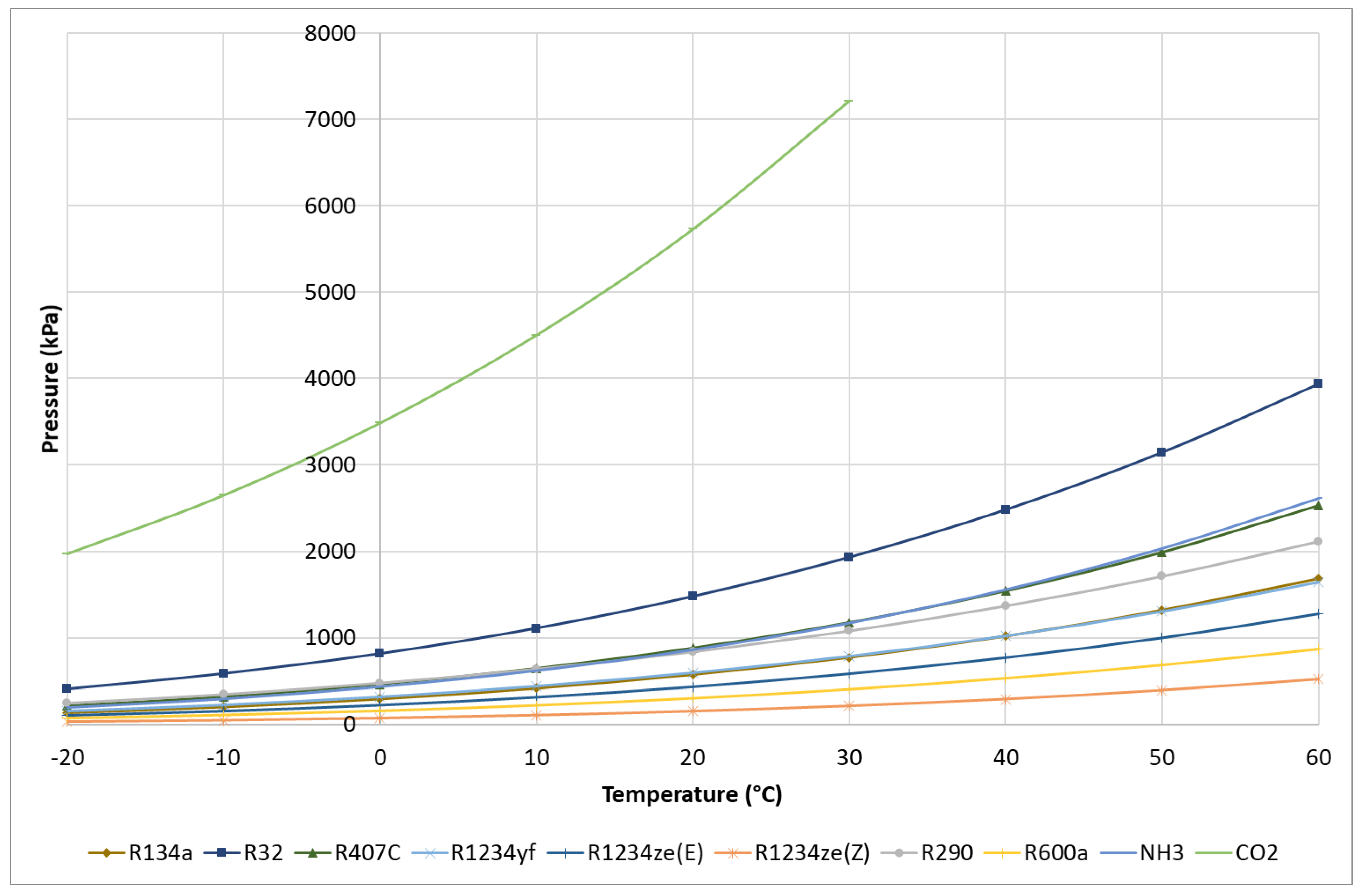
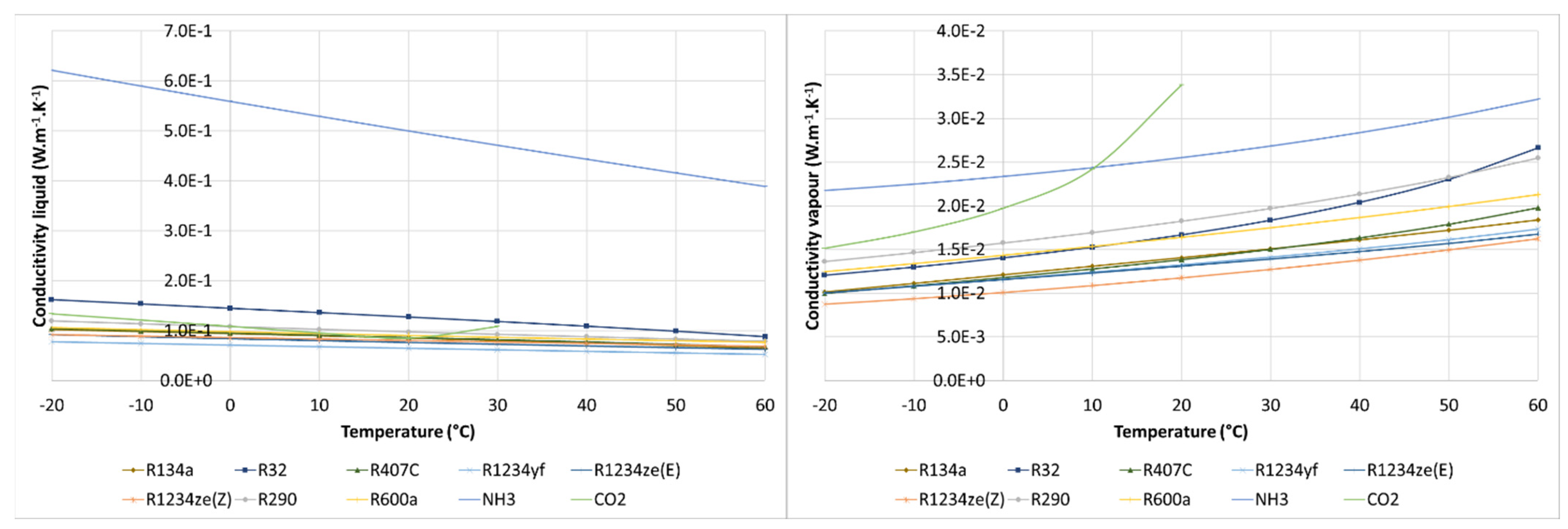
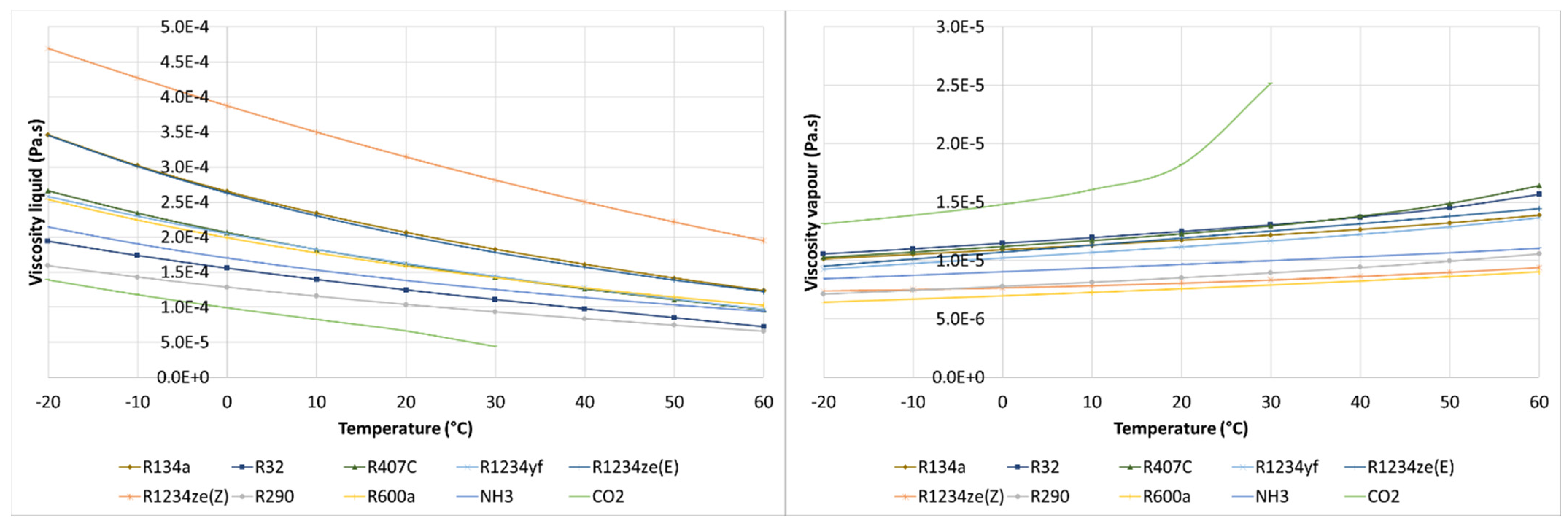
3.4. Comparison of Thermophysical Properties

For this comparison, the choice fell on at least one fluid from each large family, and 11 refrigerants have been selected:
  • CFC R12;
  • HCFC R22;
  • HFCs R134a and R32;
  • mixture of HFCs R407C;
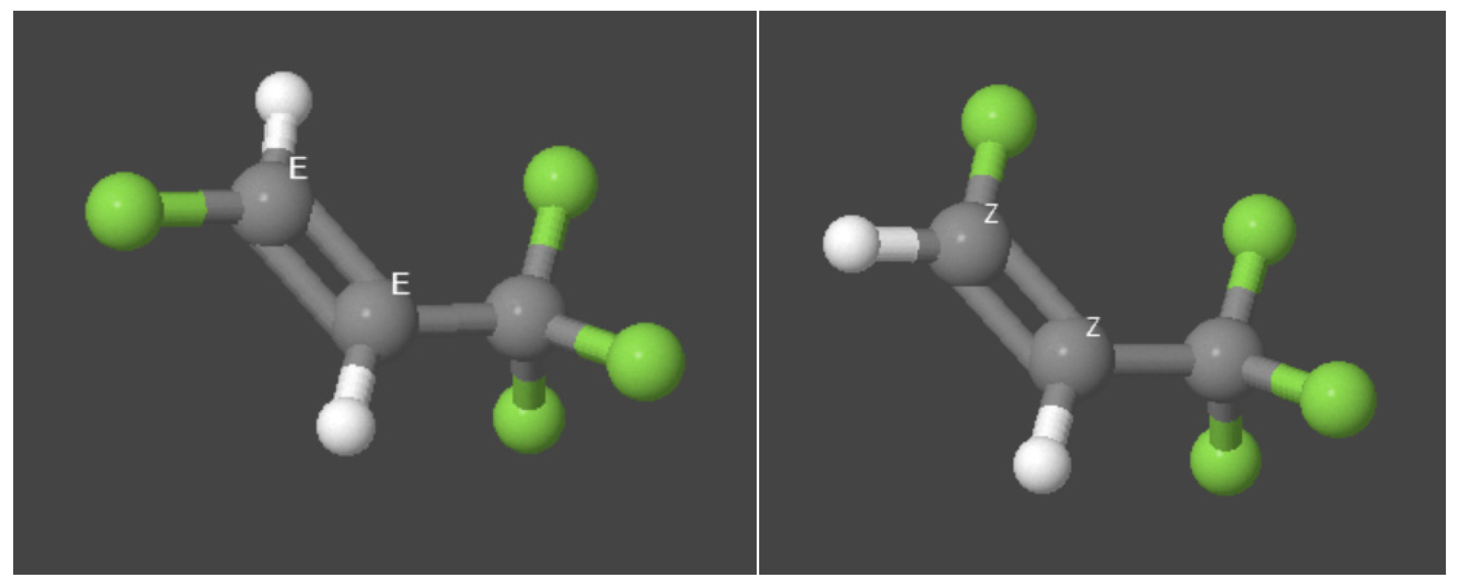
  • HFOs R1234yf, R1234ze(E) and R1234ze(Z);
  • HCs R290 and R600a;
  • NH3;
  • CO2.
Table 8 presents some thermophysical properties of R12 and R22, CFCs and HFCs most used in the past, HFCs, HCs and HFOs studied in my research on TFPs, ammonia and CO2. For each column of this table, the values are gradually presented from red for the highest value to blue for the lowest value. The molar mass of the refrigerant depends on the composition of the molecule and varies between 17.03 m3/kg for ammonia and 120.9 m3/kg for R12.
The highest critical temperature is that of R1234ze(Z), followed by those of ammonia and isobutene. These fluids are used in high temperature applications. The critical temperature of CO2 is so low that to heat water or air for heat pump applications, the previously presented transcritical cycle must be used. For other fluids, critical temperatures are around 80 and 100 °C. For hydrocarbons and its derivatives, the critical pressures are close to 40 bar. The critical pressure of ammonia and CO2 are much higher. The specific volumes of fluids at 0 °C on the dew curve (gas saturation) are reported in the third column. The HFOs R1234ze(E) and R1234ze(Z), which are however isomers, have very different specific volumes due to different electronic charge distributions. Isobutene and ammonia stand out with a high specific volume value and CO2 shows the lowest value. The specific volume can be related to the size of the compressor if combined with the latent heat of phase change. Indeed, at equivalent power and equivalent latent heat, a machine using a refrigerant having a low specific volume will have a compressor with a smaller swept volume. For the hydrocarbons and its derivatives presented here, the latent heats of change of state at 0 °C and 50 °C are generally quite similar. They tend to decrease with the complexification of the molecule. CO2 has latent heat comparable to that of hydrocarbons. On the contrary, ammonia shows latent heat three to four times higher. Fluids with a high critical temperature have latent heats of state change which vary relatively little with dew point temperature. The pressure-enthalpy diagrams of the refrigerants studied are presented in the same figure (Figure 7). The zero-enthalpy point corresponds to a temperature of 25 °C and a standard pressure of 101,325 Pa. The saturation curves for CO2 and ammonia are shifted with respect to hydrocarbons and hydrocarbon derivatives. This figure clearly shows the great latent heat of ammonia. Among the hydrocarbon derivatives, R32 exhibits the greatest latent heat.
The saturation pressures as a function of the dew point temperature are presented in Figure 8. At equivalent temperature, CO2 (R744) presents much higher pressures than other fluids. The high pressures induce greater mechanical stresses on the components of the refrigeration circuit and the connections. Different technologies are used. R32 also has a higher saturation pressure than other fluids. The fluids with the lowest saturation pressures are R600a and R1234ze (Z).
The boiling point of R600a and R1234ze (Z) at atmospheric pressure are −11.7 °C and 9.3 °C. Any application below this temperature requires perfect sealing of the installation to prevent humidity from the ambient air from entering the refrigeration circuit.
The specific thermal capacities of fluids in saturated liquid and vapor phases are presented in Figure 9. These properties are related to the exchange coefficients. Incidentally, a greater specific thermal capacity contributes to the reduction of the compressor suction temperature, since the suction gas becomes more difficult to overheat. The strongest specific heat is observed for ammonia, CO2, propane (R290), isobutane (R600a) and R32. The critical temperature of CO2 is 30.98 °C. The specific heat values of liquid and vapor at 30 °C are much higher and, respectively, equal to 35.4 kJ·kg−1·K−1 and 55.9 kJ·kg−1·K−1.
The changes in thermal conductivities in saturated liquid and vapor phases as a function of temperature are shown in Figure 10. High thermal conductivity has a favorable effect on the exchange coefficient. Ammonia is distinguished by high values. CO2 also exhibits high thermal conductivity, especially in the vapor phase at a temperature approaching the critical point. At 30 °C, the thermal conductivity of steam reaches 0.14 W·m−1·K−1.
Figure 11 shows the evolution of the viscosities of the liquid and vapor phases as a function of the saturation temperature. A low dynamic liquid viscosity corresponds to a low friction in the liquid pipes, which contributes to reducing the pressure drops in the refrigeration circuit. A high viscosity will lead to a reduction in exchanges.

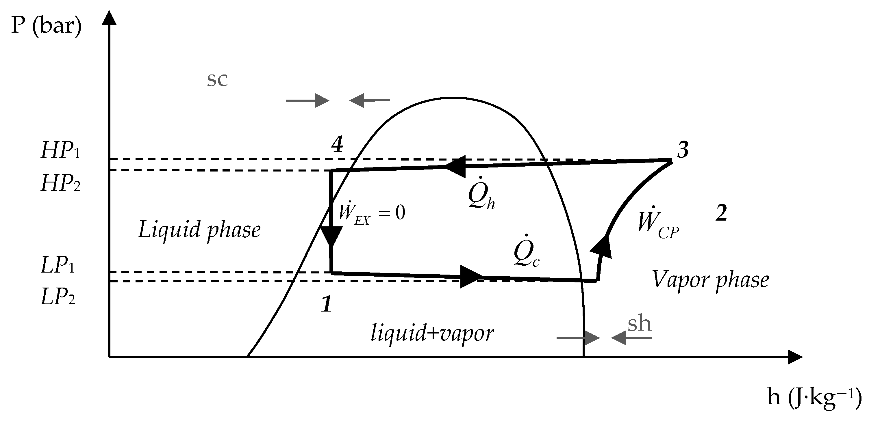
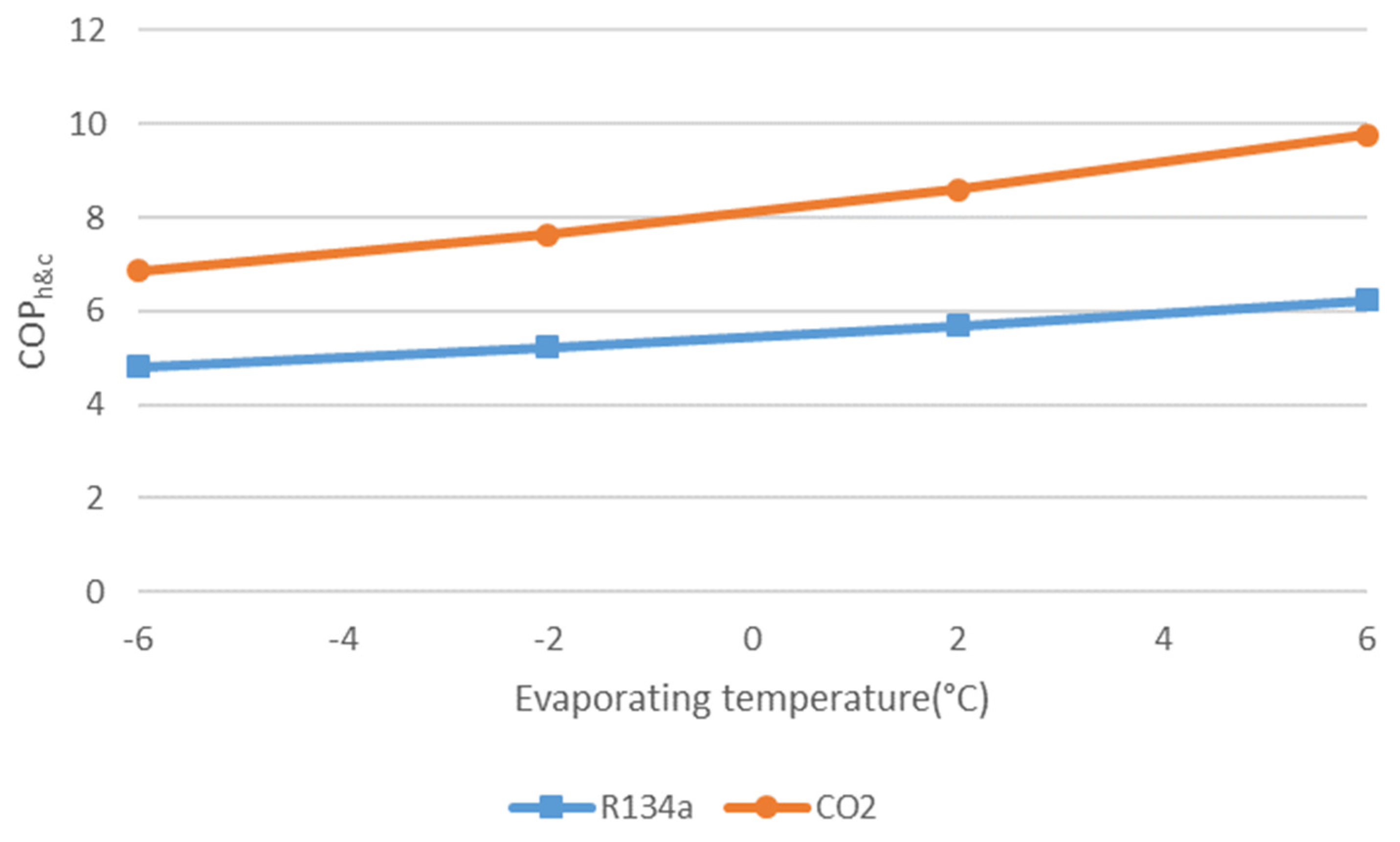
3.5. Comparison of Refrigerants through Cycle Performance

The performances of the thermodynamic cycles of the refrigerants presented in Table 8 are compared for three applications: production of hot water at 35 °C and cold water at 7 °C, for space heating and cooling and domestic hot water production at 55 °C according to the temperatures imposed by the standard tests of regulations EN14511 [47] and EN16147 [48]. Depending on the source temperatures, 5 modes are simulated according to Table 9:
mode (1) heating only;
mode (2) cooling only;
mode (3) DHW only;
mode (4) simultaneous heating and cooling;
mode (5) simultaneous DHW and cooling.
These 5 modes correspond to 4 simulations because the evaporating and condensing temperatures are assumed to be the same in modes (2) cooling only and (4) simultaneous heating and cooling.
The hot water production temperatures chosen imply higher condensing temperatures and lower evaporating temperatures than the source and sink temperatures. It is assumed that the temperature pinches in heat exchangers are equal to 5 K for water and 8 K for air. For conventional fluids, the condensation temperature is 40 °C and 60 °C, respectively, for space heating and domestic hot water production. Ambient air is assumed to be at a temperature of 7 °C as used in European standard EN14511 [47]. This ambient temperature gives an evaporation temperature of −6 °C for an assumed cooling of the air of 8 K, with the exception of the zeotropic mixture R407C, for which the temperature glide is allowed to return to an evaporating temperature of −1 °C at dew point. The cooling temperature regime is 12 °C/7 °C. The evaporation temperature is therefore 7 °C for R407C and 2 °C for other fluids. The following assumptions have been taken into account for all fluids:
  • Superheating is equal to 5 K.
  • A non-useful superheating in the suction line is equal to 1 K.
  • Subcooling is equal to 2 K.
  • Pressure drops inside heat exchangers are neglected.
  • Isentropic efficiency is equal to 0.7.
For the carbon dioxide transcritical cycle, the high pressure was calculated using the correlation of Qi et al. [41] (Equation (40)). The optimum high pressure depends on the outlet temperature of the gas cooler Tout,gc. For space heating and DHW production, the gas cooler outlet temperatures are 35 °C and 20 °C and the optimum pressures are 87.04 bar and 62.14 bar, respectively. According to this correlation, the CO2 thermodynamic cycle is very slightly subcritical for a gas cooler outlet temperature of 20 °C. However, this correlation would be valid if the hot source had only a small variation in temperature. In fact, at this pressure, the condensation temperature of the CO2 is 23 °C. and the latent heat necessary to condense the fluid is too great. The DHW cannot recover this large amount of heat at such a low temperature (23 °C) and then undergo a temperature rise to 55 °C thanks to the desuperheating energy with the same flow rate. To facilitate the comparison of cycles and ensure supercritical cooling of the CO2, the pressure of 87.04 bar is also used for modes (3) and (5) of DHW production.
The simulations were carried out with Engineering Equation Solver [49]. Figure 12 shows the COPs of thermodynamic cycles in the operating modes presented above. R407C refrigerant stands out among HFCs due to temperature slippage during phase changes. The R1234ze(Z) displays COPs slightly above other fluids. CO2 has a particular behavior. In heating and cooling only modes, the cycle performance is quite poor. In DHW-only production mode, the performance of the CO2 cycle is equivalent to that of other refrigerants. In simultaneous DHW and cooling mode, the performance is much higher. This behavior is due to the importance of the evaporating temperature. Figure 13 shows a stronger change in the COPh&c of CO2 as a function of the evaporation temperature. CO2 therefore remains an interesting fluid for HPSs as long as the outlet temperature of the gas cooler is low, therefore in DHW production modes (3) or (5), or with heat recovery after a first supercritical gas cooling. The other fluids show average performance.

3.6. Discussion on Refrigerants

Currently, no refrigerant fully meets the requirements for performance, safety and environmental protection. Each application has a selection of several particularly suitable fluids.
In order to compare refrigerants, the EES digital tool integrates easy access to the thermophysical properties of refrigerants [49] and the Coolpack application developed in the EES environment by the DTU (Technical University of Denmark) facilitates the calculation of the performance of refrigeration cycles [50].
Fluorinated fluids are the most widely used refrigerants in the world. Industrial firms manufacture substances with thermodynamic characteristics suitable for each application in the refrigeration sector. CFCs were the first family of fluids widely used for refrigeration and have been phased out due to their ozone-depleting effect. HCFCs have much less ozone depletion effect and have been used as bridging fluids towards substances having zero ODP. Today, HFCs are the most widely used refrigerants in new refrigeration equipment. However, their impact on the environment concerns global warming and the greenhouse effect. These fluids are classified by the Kyoto protocol in the category of greenhouse gases. Thanks to a relatively low GWP of 650, R32 is increasingly used in air conditioning. However, HFCs are therefore already subject by the European F-gas regulation to a schedule setting bans on fluids with a GWP above thresholds of 150, 750 or 2500 depending on applications to reduce the risk of leakage and exposure of people to these fluids. To anticipate these constraints, new synthetic fluids from the hydrofluoroolefin (HFO) family have appeared on the market and offer very low GWP. Other alternative fluids are currently being researched in the chemical industry to meet the requirements of low GWP and high performance.
In the environmental context, the return to “natural” refrigerants, i.e., naturally present in the environment, is becoming a promising alternative in the development of new heat pumps. Among natural fluids, three candidates stand out: hydrocarbons, carbon dioxide and ammonia. However, safety constraints in buildings prohibit the use of ammonia. The next international regulations will push manufacturers of small heat pumps to develop machines using low GWP refrigerants. The literature review identified several candidates among pure fluids: some hydrocarbons, HFOs and CO2. Hydrocarbons exhibit good performance but are highly flammable. A charge limitation is applied to small heat pumps in occupied rooms. HFOs are less efficient, also have little impact on global warming, but are more expensive because of their synthesization costs. HFOs are sometimes slightly flammable and present a potential risk of acidification of watercourses. CO2 is very efficient in DHW production but not in space heating. The high operating pressures require the use of more expensive components than for other technologies. So today there is no low GWP fluid that is ideal for HPSs.
In the future, it would be interesting to approach ammonia heat pumps in industrial applications because this fluid has the best thermodynamic properties. Propane (R290) is the hydrocarbon that has been chosen for several studies because of its average pressure levels and good performance. The outlook is, however, limited due to the flammable nature of the hydrocarbons. Particular attention has been paid to CO2 because its unique thermophysical characteristics give it advantages for the production of hot water at high temperature. Heat pumps have a dual service operation in which performance is assessed in a different way from other thermodynamic systems so that their development is an opportunity to support the use of this natural refrigerant with unique behavior.

4. Applications of Heat Pumps for Simultaneous Heating and Cooling

An analysis of heating and cooling demands is discussed in Annex 48 of the Energy Conservation in Buildings and Community Systems (ECBCS) program of the International Energy Agency [51]. The title of this annex is “Heat Pumping and Reversible Air Conditioning”. The document presents buildings with simultaneous or slightly delayed heating and cooling demands. It details the possible solutions to satisfy this type of demand in tertiary and medical buildings. The applications identified so far are:
  • low and high temperature ambient heating;
  • ambient cooling or air conditioning (with humidity control);
  • domestic hot water production;
  • seawater or brackish water desalination;
  • commercial refrigeration;
  • industrial refrigeration;
  • industrial processes.
The energy saving potential of a heat pump for simultaneous heating and cooling (HPS) compared to a reversible heat pump system strongly depends on the existence of simultaneous or slightly delayed heating and cooling demands. The production imbalance is compensated either by operation on a free source, or by an auxiliary device. An external source of heat or cold is therefore sometimes necessary to compensate for the imbalance of production and demand. A second report in Annex 48 (ECBCS IEA) lists the free external usable sources cited below [52]:
  • the outside air;
  • the air extracted by mechanical ventilation;
  • groundwater from water tables;
  • surface water;
  • a building water loop as an internal balancing network;
  • wastewater;
  • condensed water from cooling towers;
  • the ground by a water loop in a geothermal well or by a direct expansion of refrigerant fluid;
  • solar collectors;
  • heat rejected by industrial processes.

4.1. Simultaneous Heating and Cooling in Buildings

The use of a heat and/or cold storage system enables to increase operating times in simultaneous mode to be able to meet deferred demands over short periods. The simultaneity of demands can be assessed by calculating a ratio of simultaneous needs (RSNs), a method developed by Ghoubali et al. [53] to qualify buildings with regard to the benefit of a heat pump (Equation (41)). The higher the RSNs, the more the heat pump will tend to request simultaneous mode. This ratio is defined as the minimum between the ratio and its inverse of the heating and DHW needs over the cumulative cooling needs over a day, the assumption being that storage tanks large enough to contain the daily production are associated with the HPS.
R S N = min ( Q h + Q D H W Q c , Q c Q c + Q E C S )
Previous works enabled to evaluate the simultaneous demand of typical buildings having a floor area around 1.000 m2 such as a hotel of 45 bedrooms [54] using TRNSYS software [55]. Ghoubali et al. studied three other typical buildings: a low-energy collective residential building, a shop and an office building [53]. Three different climates were simulated: oceanic (Rennes, France), continental (Strasbourg, France or Brussels, Belgium) and Mediterranean (Marseille, France). The simulation parameters are given in Table 10. DHW daily consumptions are estimated in liters per day according to estimates cited in specialized literature.
  • Hotel: 135 L/day and per person at 60 °C [56].
  • Residential: 40 L/day and per person at 60 °C [56].
  • Offices: 5 L/day and per person at 60 °C [57].
  • Shop: 10 L/day and per person at 45 °C [56].
For the oceanic climate of Rennes, the calculated ratio of simultaneous needs over the year are given by Ghoubali et al. for the cases of the hotel, the residential building, the office building and the store without additional cooling needs for food. In the hotel and the residential building, the RSNs are higher in the summer period, when the domestic hot water needs are coupled with the cooling needs. The office building has more air conditioning needs because of the high internal gains of the equipment and the server room. The retail store has very little heating requirement in the summer.
These results are completed in Table 11 by two simulations adding to the store model cooling demands for display cabinets and for a cold room for storing food products. An optimization function was used to determine the cooling requirements leading to the maximum RSNs. The cooling demand was evaluated at 104 kWh per day. The RSN is very dependent on the cooling demand. Table 11 groups together the RSN values as an annual average for the residential building, the offices and the store for oceanic (Rennes), Mediterranean (Marseille) and continental (Strasbourg or Brussels) climates. The maximum RSN is obtained for the residential building with the Mediterranean climate of Marseille.

4.2. Simultaneous Cooling and Desalination

Figure 14, adapted from a previous publication [58], highlights the simultaneity of cooling demands and freshwater needs. It compares the increase in temperature due to climate change between 1901 and 2012, the cooling degree days (CDD) and solar resource issued from the weather files based on typical meteorological year from TRNSYS [55] and the precipitation decrease per inhabitant (PDPI) between 1951 and 2010 in five cities of the world. The increase in population has been factored into the calculation. The decrease in precipitation is considered to be potentially an increase in freshwater production by desalination. This graph shows that, in areas where the sum of cooling degree days is high, the decrease in precipitation in 60 years was greater than the average value for the five cities, represented by level 1 on the y-axis. It is thus possible to detect a potential for significant simultaneous needs for cooling and desalination.
In a recent article dealing with deep seawater cooling and desalination, the assessment of simultaneous cooling and desalination demands was enlarged to the 162 major coastal cities all around the world (Figure 15) [59]. The first part of the study especially identifies the cities where the cooling degree days and the precipitation decrease per inhabitant are simultaneously higher than the average (Figure 16). These cities are globally situated close to the equator.

4.3. Discussion on Simultaneous Heating and Cooling Demands

A heat pump for simultaneous heating and cooling can be chosen and sized thanks to the RSN. In the applications presented above, the rate of simultaneous needs is between 15 and 30%, which can correspond to a sufficient level to cover the extra cost of a HPS compared to a standard heat pump. Indeed, for the example of the store, when the commercial refrigeration needs increase well above the heating needs, the RSN drops sharply. In the case of strong needs at 730 kWh, a thermo-refrigeration pump could provide 104 kWh of cold per day and would be supplemented by a cooling unit for the rest of the needs. A HPS should be connected to heat and cold tanks in order to increase the RSN. Additional simulations have shown that a time of integration of requirements over a period shorter than a day, which would correspond to an under-sizing of the storage system or no storage at all, would lead to a significant reduction in the simultaneity of thermal needs. Therefore, storage tanks should be sized to cover the needs of at least one day.
Simultaneous cooling and desalination is a good application for heat pumps, especially in hot coastal areas. The freshwater can be stored easily and for a long duration. The operation of the system can be driven by the cooling demand only. The freshwater is then a free byproduct.

5. Literature Review of Simultaneous Heating and Cooling Heat Pump Systems
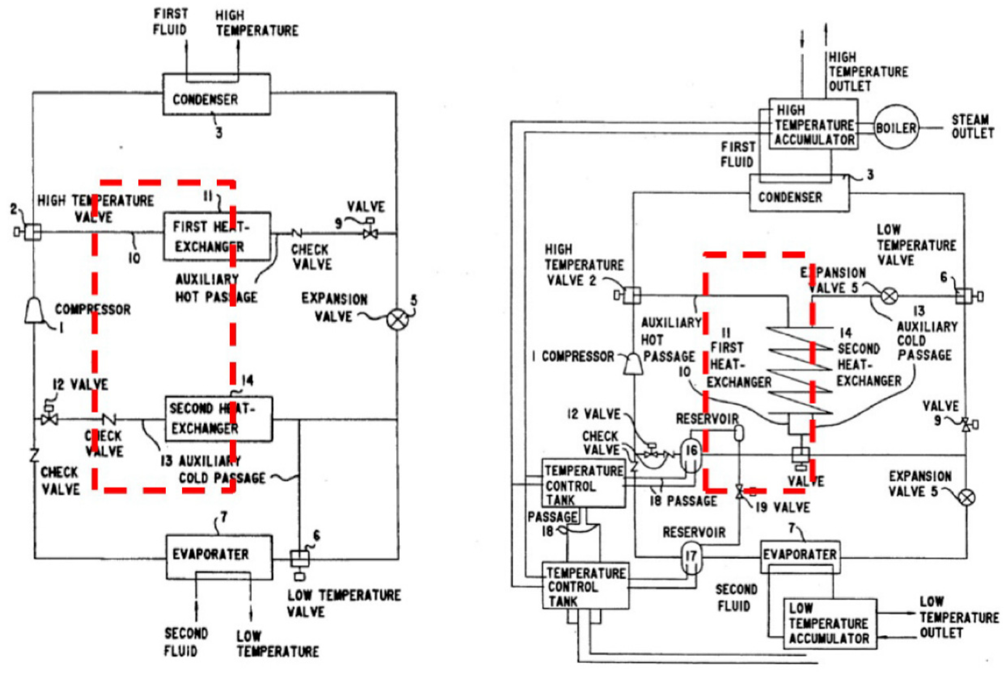
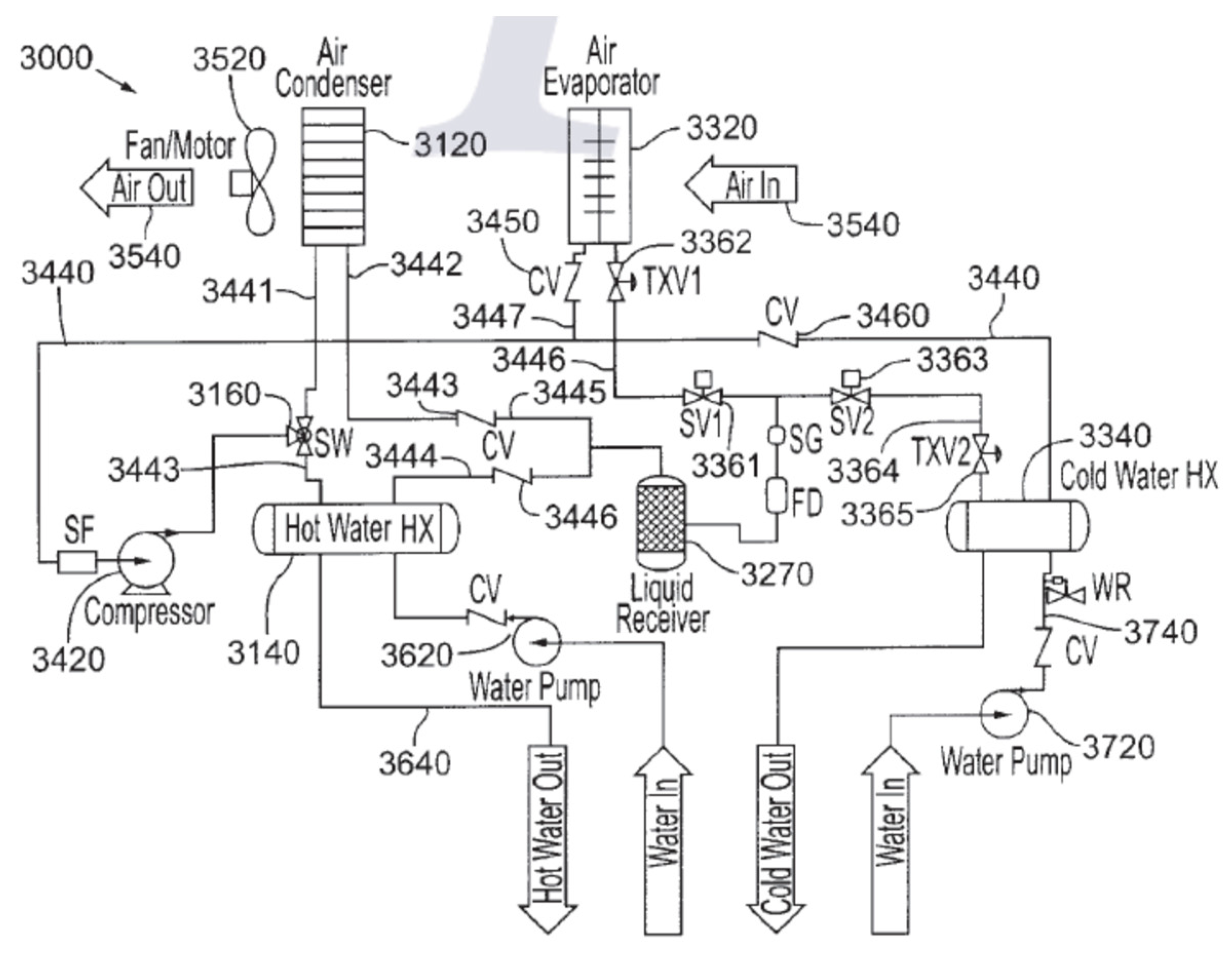
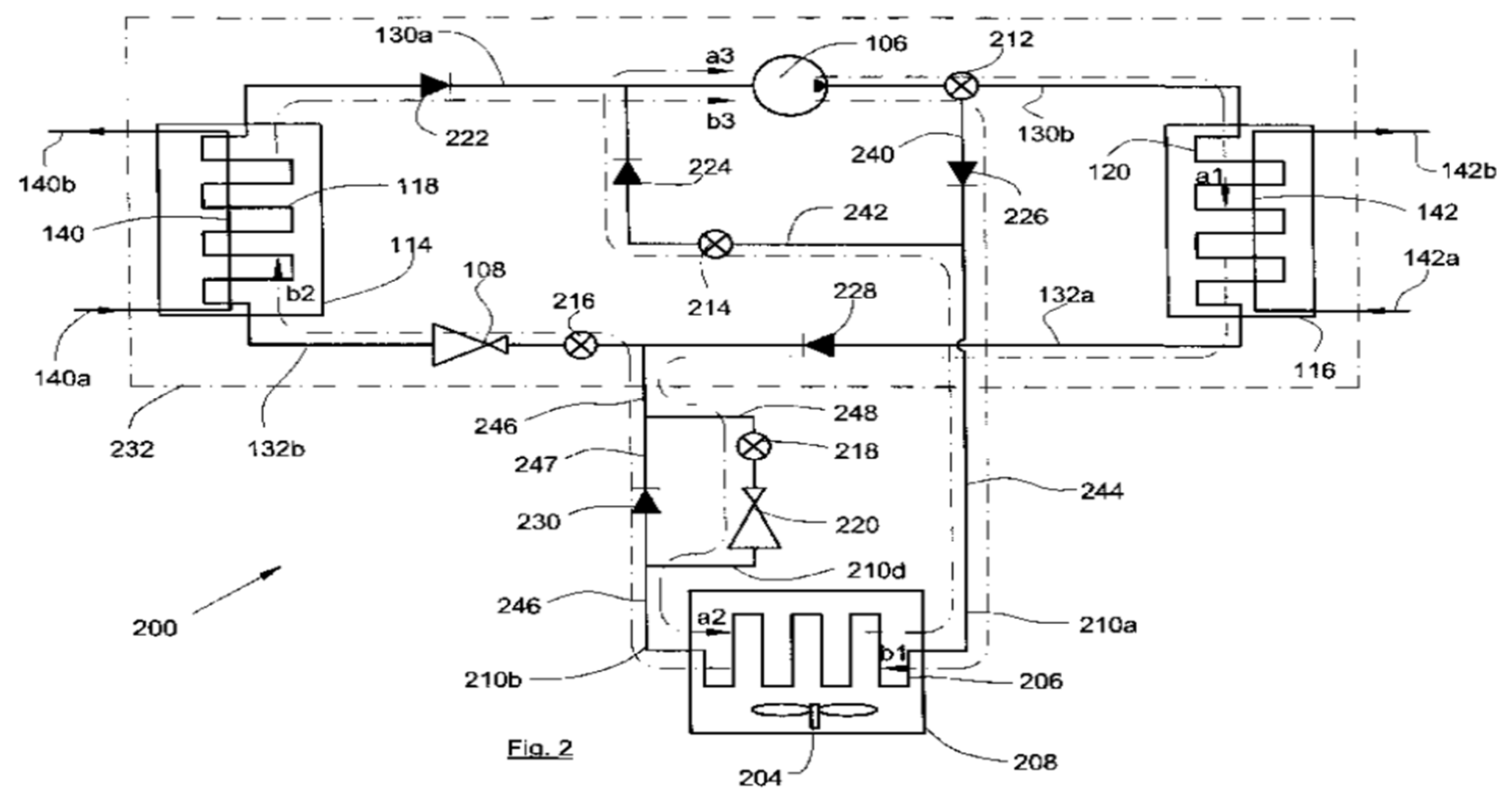
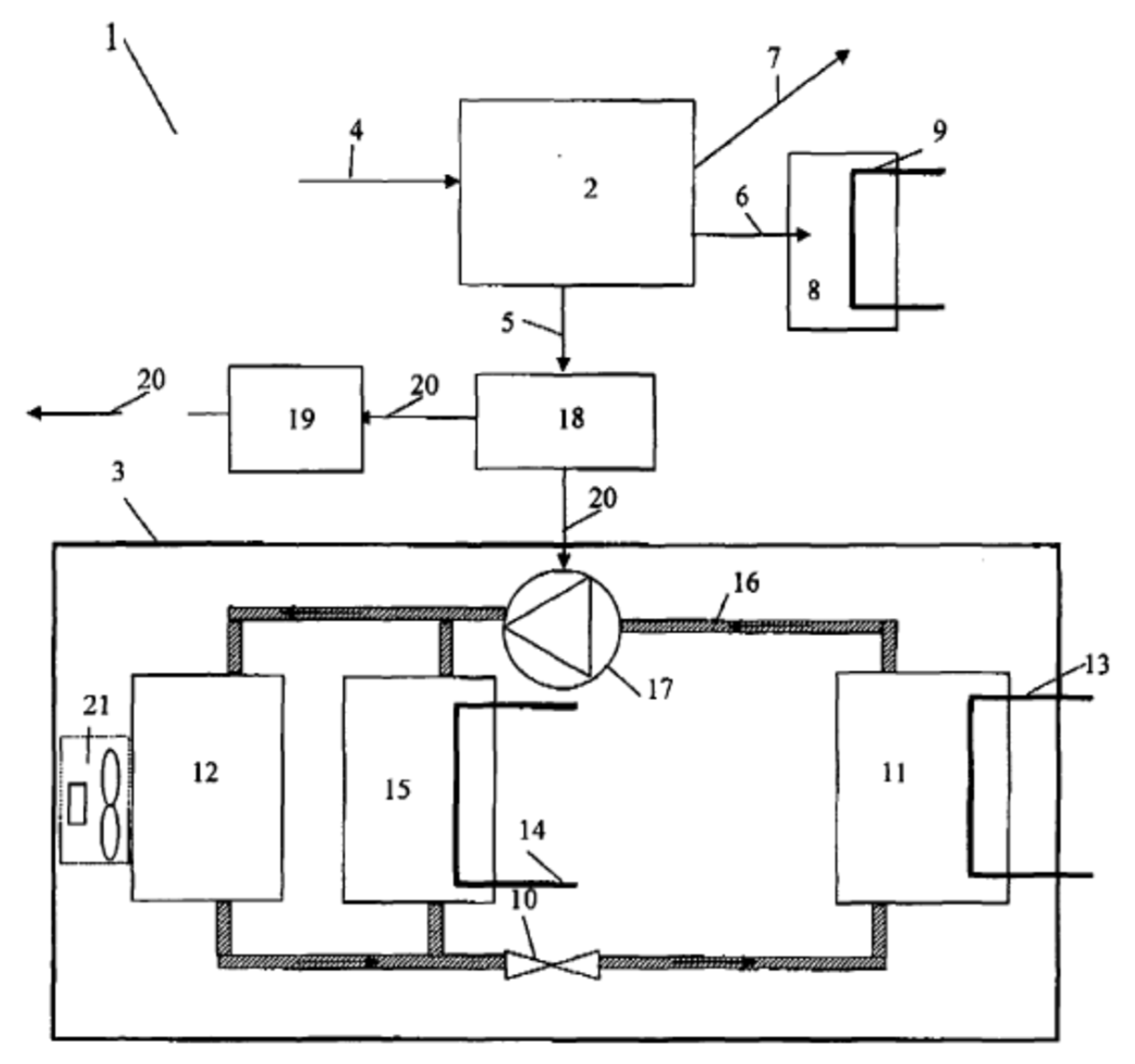
This section reviews the patents deposited and the scientific studies carried out on heat pumps for simultaneous heating and cooling

5.1. Patents

The first patent that comes closest to a HPS was registered in 1952 (Zimmerman US2581744) [60]. The inventor notes that this system is suitable for extreme North American climates. This configuration includes two refrigerant/water exchangers and a balancing air exchanger. One of the water exchangers is connected to a pipe buried underground to switch to a water-to-water heat pump during periods of extreme cold in order to avoid a build-up of severe frost on the air exchanger. This device eliminates the need for a defrosting system and thus increases the performance of the machine. In this patent, there is no clear mention of simultaneous production of heat and cold. However, this is what the refrigeration circuit of the system allows. A patent that describes the operation of a heat pump suitable for simultaneous production was deposited by Harnish on behalf of Westinghouse Electric Corporation (US3264839) in 1966 (Figure 17) [61]. This heat pump is the combination of a water-to-water heat pump and an air-to-water heat pump. The air exchanger operates either as an evaporator in series with the water evaporator when the heat requirements are greater than the cooling requirements or as a condenser (in addition to the water heat exchanger) when the cooling requirements are greater. The refrigerant exits as a liquid vapor mixture from the water evaporator. This mixture is poured into an accumulator. The vapors are sucked in by the compressor while the liquid at the bottom of the bottle is reinjected after expansion using a pump into the air exchanger.
A heat pump diagram intended for heating (or cooling) and simultaneous production of domestic hot water (DHW) is presented in the patent of Mitsubishi Denki Kabushiki Kaisha (US4592206) in 1986 (Figure 18) [62]. In this configuration, three types of heat exchangers exist: two internal air exchangers, one external air exchanger and a coil exchanger for the DHW production. A three-way valve at the compressor outlet distributes the vapor, depending on the mode, to the DHW heat exchanger or to a four-way valve. The combination of the two valves allows one to switch between the different operating modes. There are four operating modes:
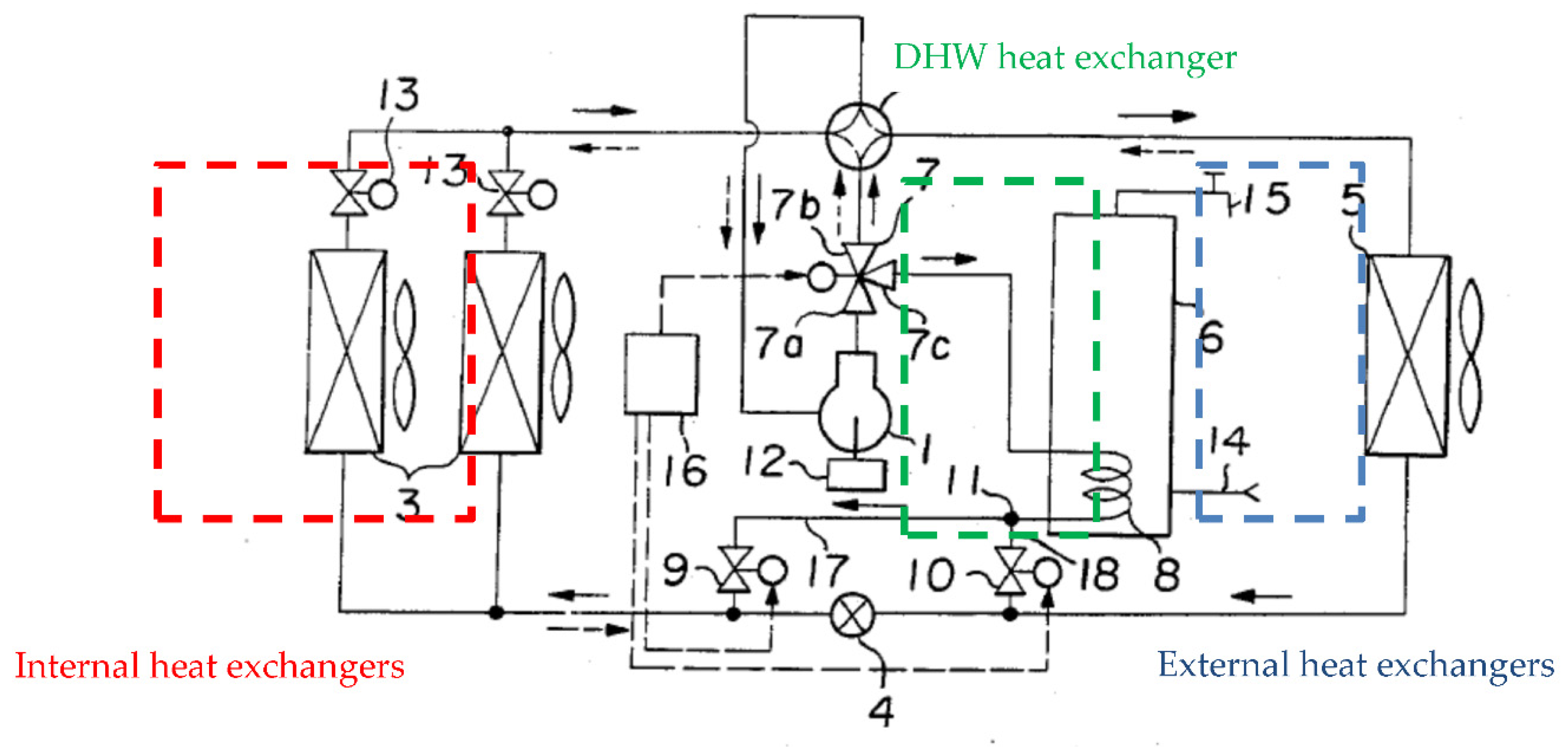
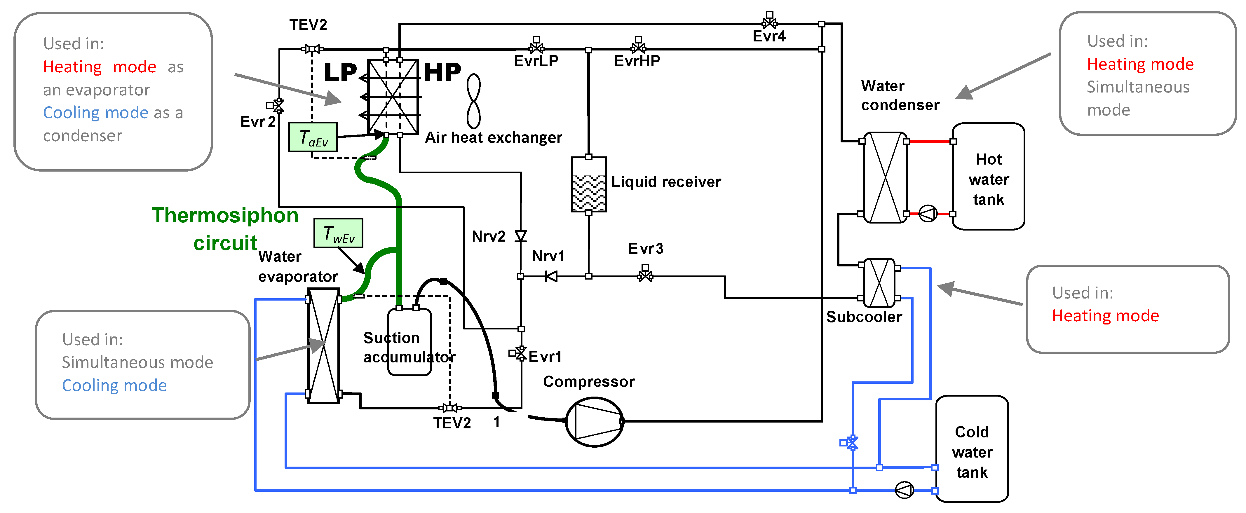
  • Heating only mode (condensation in the internal exchangers and evaporation in the external air exchanger).
  • Heating and DHW production mode (condensation in the internal exchangers as well as the coil and evaporation in the (external air exchanger).
  • Cooling only mode (condensation in the external air exchanger and evaporation in the internal exchangers).
  • Cooling and DHW production mode (condensation in the coil and evaporation in the internal exchangers).
In domestic hot water and heating production mode, the internal exchangers and the DHW exchanger are supplied either in parallel or alternately with changeover depending on the temperature in the room, in heating only or DHW production only modes.
Matsuura described in the patent (US5211023) in 1993, on behalf of Union Kogyo Kabushiki Kaisha, a device for producing heat and cold simultaneously (Figure 19) [63]. This diagram includes a condenser, an evaporator and two balancing heat exchangers on air or on water, framed in red in Figure 19. Two three-way solenoid valves are necessary (high temperature and low temperature solenoid valve) in order to switch to one of the balancing exchangers when there is an imbalance of needs. In the diagram on the right called FIG. 8 of the same patent, the two exchangers are replaced by a single exchanger that operates, depending on the mode, either as an evaporator or as a condenser.
The patent for a simultaneous heating, cooling and dehumidifying device was presented by Jungwirth (US6751972) in 2004 (Figure 20) [64]. The same operating logic as in the Matsuura patent is observed with two heat exchangers for the production of water (hot or cold) as well as two balancing air heat exchangers (evaporator and condenser). A three-way valve at the compressor outlet supplies either the water condenser or the air condenser. There are four operating modes: simultaneous mode (production of hot and cold water), heating only mode (with condensation on water and evaporation on air), cooling mode (evaporation on water and condensation on air) and dehumidification mode (evaporation and condensation on air).
The patent of CLIMATIK Sarl (FR2886388) in 2005 describes a heat pump similar to that of the patent of Matsuura (Figure 21) [65]. Three heat exchangers are required in this diagram: a condenser, an evaporator and an air balancing exchanger. The passage of refrigerant in the water or air condenser is controlled by a three-way solenoid valve at the compressor return flow.
Mobile comfort holding (EP2085721-2009) has developed a multi-energy device with simultaneous production of hot water, cold water and electricity (Figure 22) [66]. This system consists of a heat pump and an electricity production system (either a combustion engine associated with an alternator, fuel cell or solar panels). In the case of simultaneous needs, the two water exchangers are used. A third air exchanger is used in the absence of heat requirements. The heat is recovered from the electricity production system (from the cooling circuit and from the engine exhaust gases in the case of the combustion engine, for example) in order to evaporate the refrigerant and thus produce hot water at very high temperature.
Ghoubali et al. from our research group deposited a patent on a new architecture of heat pump for simultaneous heating and cooling (Figure 23) [67]. The machine components are a desuperheater, a water condenser, a water evaporator, a subcooler and a balancing air coil. The innovation relies in the presence of two four-way valves in the refrigeration circuit to avoid trapping refrigerant charge in unused parts of the circuit in every operating mode.
According to the list of patents, some common characteristics can be pointed out. Three-way valves are frequently used of at the compressor outlet. Balancing heat exchangers are systematically installed on the refrigeration circuit in order to adapt production to heat and cold demands. If the Mitsubishi patent is excluded, the control strategy is not described. Indeed, the logic of control and command is the most important aspect in a machine that comprises several operating modes, and its disclosure, even in a protected framework, is not desirable because it constitutes a know-how about the technology.

5.2. Scientific Articles

The oldest publication found on heat pumps for simultaneous heating and cooling dates from 1964. The thermodynamic plant at the ORTF house is one of the first realizations of a heat pump with an air balancing exchanger. This low inertia building is heated or cooled depending on the areas by radiant ceilings [68].
The theoretical work of Le Goff [69] presents a system optimizing method as a function of exergy efficiency and an economic or ecological performance factor. Specific performance indicators are therefore used in order to better assess the improvements made by HPSs.
Lecrivain et al. [70] show the performance of a heat pump that produces hot water at 95 °C and chilled water for the food industry. The machine is built with two cooling circuits in cascade. The hot water production stage uses R114, and the cold-water production stage works with R22. A subcooler on the R114 stage and a balancing air condenser on the R22 circuit have been added to increase performance and provide more flexibility in operation. This solution has made it possible to save 36 toe (tons of oil equivalent) annually compared to a solution combining a refrigeration unit and a natural gas boiler.
Ghosh et al. [71] quantified the economic benefits of introducing systems for the simultaneous production of heat and cold in industry. They exhibit a payback time that depends on the investment cost, annual savings from simultaneous production and annual fixed capital. They found that for electricity costs in India, a heat pump with simultaneous production has a payback time of less than 18 months.
Energy savings are thus achieved through the use of this type of refrigeration equipment connected to radiant floors or ceilings, air handling units and fan coils. In France, several HPSs with groundwater balancing exist in public and industrial buildings such as the CAF of Lyon (600 kW heating and 600 kW cooling) [72,73], Le Brabant building in Paris, rented by the Ministry of Justice (two groups of 180 and 460 kW cooling) [74], the head office of the company Havas in Suresnes in the Hauts-de-Seine (three groups of 600, 750 and 100 kW cooling) [75] and the world headquarters of Infogrames in Lyon (3 groups for a total power of 1500 kW electric) [76].
Buildings in the computer and food industries have strong heating and cooling needs in their manufacturing processes. The IBM plant in Corbeil is equipped with a heat pump with two cascading circuits of powers of 1880 kW heating and 1770 kW cooling [77]. White et al. present the study from a technical, economic and environmental point of view of a CO2 refrigeration and hot water production installation for the food industry with 115 kW heating capacity [78].
The Protestant Infirmary of Caluire (Rhône) is equipped with a heat pump heating and cooling system connected to an air handling unit and to fan coils used for heating only. The heat pump is assisted by two reversible air-water heat pumps that can work on the same water loop or on different water loops. Thus, 56% of the heating needs could be covered by energy recovery from the cold-water loop [79]. A music school in Biarritz (300 kW cooling and 400 kW heating) [80] operates with a Rhoss brand heat pump patented under the name “Exergy”.
An air treatment and sanitary hot water production facility is proposed by Gong et al. [81]. A prototype of 7 kW cooling nominal capacity was built. The two water (DHW production) and air (balancing) exchangers are arranged in series. The prototype was tested under different climates and the coefficient of performance achieved is equal to 6. Following this study, an R22 refrigeration installation with a power of 1750 kW was modified in order to simultaneously produce DHW and cold water [82]. A heat rejection exchanger to outside air is arranged in series with the water condenser for producing domestic hot water.
An experimental and numerical study is presented in the publications of Sarkar et al. [83,84,85]. He has developed a CO2 HPS, of which all prototype components are made of stainless steel. The authors used a Dorin compressor rated at 2.5 kW at 2900 rpm. The evaporator and the gas cooler are coaxial countercurrent exchangers. A model developed from their experimental data calculates the energy and exergy performance of the system.
Fatouh and Elgendy [86] have developed a prototype of a water-to-water heat pump using R134a. This equipment can operate in heating, cooling or simultaneous modes. The coefficient of performance in simultaneous mode is defined as the ratio of the sum of the useful powers to the electric power absorbed.
Agrawal and Bhattacharyya [87] conducted a study on the simultaneous application of heating and cooling with a heat pump operating on CO2. They have shown that there is an optimal demand for which the system gives the best COP.
Liu [88] analyzed in 2013 the performance of a multi-function heat pump in heating mode using an air evaporator and a water evaporator. The two evaporators are either separate and combined in parallel or in series. He concluded that the system with the two evaporators in parallel has the best performance (cooling COP greater than 5 in all configurations) in both modes (space heating mode and space heating mode plus domestic hot water production), for example compared to other systems. In 2014, Liu et al. published a new study on a HPS with two balancing sources, gray water and outside air [89]. They obtained a heating COP between 4.8 and 5.8 depending on the operating conditions.
Kang [90], Joo [91], Jung [92] and Boahen [93] worked on the same project for heating and cooling by varying the operating conditions with partial load and using optimization methods. Their prototype of 8 kW cold reached a maximum COP of 7.69. They more recently studied a cascade version of their multi-heat pump system that showed a stable behavior under variable outdoor conditions. Fricker and Zoughaib studied flexible solutions for the simultaneous production of heat and cold by combinations of heat pumps [94]. Better performance was obtained, in particular in the minimization of overproduction of high exergy heat. Flexibility is also achieved here by a variable speed compressor and fan.
More recently, new studies have shown the diversity of sources and applications. Liu et al. evaluated the improvement in the energy performance of heat pumps in seven processes in the food industry [95,96]. These HPSs, operating either with ammonia (NH3) or with CO2, had, depending on the configuration, two-stage cycles, internal liquid/vapor exchangers or even multiple condensers. Yang et al. compared electric and absorption heat pumps for the simultaneous heating and fast cooling of beverages [97]. The performances of the two systems were close. Shin et al. developed a simulation model of a heat pump system using multiple sources: hot water, domestic hot water, cold water, geothermal well and wastewater [98]. Data centers are other buildings with a high simultaneous demand for heating and cooling. Deymi-Dashtebayaz et al. present a system that is decoupled in the heat and cold production cycles but coupled in the heat sources and sinks [99]. Using a simultaneous production, the data center’s energy efficiency is improved by 16%.
The simultaneous heating and cooling can be achieved by sorption heat pumps either by absorption in a moving liquid describing a cycle or by adsorption in a solid material. In 1987, Best et al. define the interaction between hot and cold cycle temperatures [100]. Zheng et al. show that an absorption machine assisted by solar collectors can achieve significant primary energy savings [101]. This heat pumping technology is not standard presently and therefore less widespread than vapor compression heat pumps.
Pardinas et al. present an integrated energy system that consists of a centralized refrigeration unit can deliver the entire HVAC&R (heating, ventilation, air conditioning and refrigeration) demand for a supermarket [2]. The system COPh&c was measured at 3.24, which is high for a CO2 transcritical HPS in real conditions. Simulations run with Modelica showed that an ejector and a floating receiver would even increase the COPh&c up to 3.72. Wang et al. also measured the COP of a CO2 transcritical heat pump for simultaneous space heating and cooling at a value of 3.27 [102]. An optimization phase still remains to be conducted in order to correct the slow operation of a three-way valve. Finally, Artuso et al. present the numerical model of a CO2 unit, which can operate according to a chiller or heat pump configuration. They obtained an experimental COPh&c equal to 4.87 [103].
Shin and Jeong highlight the issue of unbalanced heating and cooling demands in buildings [104]. They propose to let the indoor temperature derive to increase the operating time in a simultaneous mode. Using a TRNSYS simulation, they show that this strategy enables to save a significant amount of energy and much more if a storage tank is used.
Our research group has worked on heat pumps for simultaneous heating and cooling to improve their performance and to push for their development. Figure 24, adapted from the original publications [105,106], shows the schematic diagram of the first HPS prototype. The principal components are a scroll compressor, a water condenser, a water evaporator, an air heat exchanger (air evaporator or air condenser depending on the operating mode) and two thermostatic expansion valves (TEV) depending on the heat source. Three modes can be activated depending on the status (open or closed) of electronic valves (Evr): heating only, cooling only and simultaneous mode. The liquid receiver is controlled in pressure thanks to EvrHP and EvrLP. Hot- and a cold-water tanks are connected to the system in order to increase the RSN. The subcooler is used during winter in a heating only mode when there is no cooling demand to heat the cold-water tank from around 10 to 20 °C. The cold-water tank then constitutes a heat source for an operation in a simultaneous mode. Therefore, during winter, the HPS will alternate between heating and simultaneous modes. This alternating sequence enables to benefit from a higher COP during part of the time and to enhance the seasonal COP. In addition, under frosting conditions, a thermosiphon is created between the cold air evaporator (at TaEv) and the hotter water evaporator (at TwEv). The thermosiphon naturally defrosts the air heat exchanger [106]. The experimental performance was verified [105]. Table 12 reports the simulations run with this system equipping hotels and a low-energy residential building in Rennes, Paris, Marseille and Brussels. The following results are found:
  • A HPS improves the seasonal coefficient of performance compared to a reversible heat pump. The improvement can reach up to 20% depending on the study case.
  • Seasonal coefficient of performance and exergy efficiency are better when simultaneous demands are high. The exergy efficiency is very sensitive to this aspect.
  • CO2 exhibits better performance improvements than R407C when switching from a reversible heat pump to an HPS.
  • The propane used in a HPS gives better energy and environmental performance than HFC R407C and HFO R1234yf.
  • The environmental impact assessed in terms of TEWI is reduced by the use of a HPS compared to a reversible heat pump.
Very recently, other authors highlighted the advantages of heat pumps integrated in industrial processes using heating and cooling. Ahrens et al. investigated an energy system for a dairy with high temperature heat pumps and thermal storage tanks achieving a total system COP of 4.1 despite an energy-intensive operation [107]. Another system for a dairy consisting of a waste heat-solar driven ejector-solar assisted heat pump for simultaneous heating and cooling purposes was studied by Al-Sayyab et al. [108]. They also studied their system for the application of simultaneous cooling of a data center and waste heat utilization for a district heating system [109]. They carried out an intensive work regarding the refrigerant choice in order to reduce CO2 emissions in terms of TEWI while increasing energy savings thanks to the overall performance of their system. Calise et al. worked on the thermo-economic study of a solar-driven district heating and cooling network involving ground source heat pumps and heat pumps for simultaneous heating and cooling [110]. The need to increase the simultaneity of heating and cooling demands is highlighted. In case of district system, the solutions identified are additional energy storage and the inclusion of more types of consumers. Quirosa et al. also studied the heating and cooling productions of CO2 booster heat pumps for an ultra-low temperature district network. Among other quantified interesting results, their energetic and economic analysis highlighted that they work with lower temperatures supply, that they need to increase and adapt the energy and that they cover heating and cooling demand simultaneously [111].
The coupling of HPSs with renewable energy was investigated in recent years. Solar PV/T panels were associated with a cascade heat pump for combined cooling, heat and power in tropical climate area by Kong et al. [112]. The payback period was below 8 years.
Few studies exist on refrigeration machines coupled with desalination systems. Amin and Hawlader [113] and Attia [114] are exceptions. The former studied the influence of compressor speed on the performance of a desalination system using an R134a heat pump assisted by a solar system. Attia worked on desalination by crystallization. The cold produced to crystallize seawater is then used for another application.
Air conditioners reject huge amounts of heat, especially in hot areas of the world. Recovering this energy to desalinate water appears as a seductive idea. Membrane distillation (MD) seems to be an interesting technique because of the compatibility of the process with the condensing temperature of air conditioners. MD is a process using a microporous and hydrophobic polymer membrane (reverse osmosis membranes are nanoporous). The hydrophobic nature helps prevent liquid water from wetting and passing through the membrane. At the surface of the membrane, water evaporates under the effect of a vapor pressure gradient existing between the two sides of the membrane. This gradient is produced by a thermal gradient or by a vacuum pump. In the condensation zone, the water becomes liquid again in a pure form. The hydrophobic and microporous membrane materials are polyvinylidene fluoride (PVDF), polytetrafluoroethylene (PTFE), polypropylene (PP) and polyethylene (PE). In applications encountered in the literature, they are flat and have a thickness of about 0.2 mm. A plastic mesh-shaped spacer is usually placed inside a gap to limit membrane deformation and maintain a uniform gap over the entire surface of the module.
With MD, the rate of salt rejection is very close to 100%. Unlike reverse osmosis, this process is very little dependent on the salinity of the input solution. MD would be less sensitive to fouling than reverse osmosis (RO) because the absence of high pressure (as in RO) associated with the hydrophobicity of the membrane would create a permanent liquid film between the membrane and the possible deposit. A second factor is the low additional thermal resistance created by the presence of the deposit compared to the high mechanical resistance in the case of reverse osmosis.
For all desalination systems, pre-treatment and post-treatment must be applied. The pretreatment generally consists of microfiltration and ultrafiltration in order to trap suspensions and microorganisms. Other less widely used processes such as aeration, acidulation, addition of anti-corrosion, anti-scale, adsorption and ion exchange. Post-treatment is a dilution of minerals in distilled water to make it drinkable. Rejecting brine with more salt content can cause environmental damage. The techniques encountered are the mixing of the brine with the water rejected by another industrial process, the creation of a large diameter water jet to disperse the brine on the surface. The rejection in the seabed seems to be a less good idea because on the one hand, the underwater flora would be more directly confronted with the high salinity of the brine and on the other hand, because the seabed is generally less agitated than the surface of the sea.
The main performance indicators of desalination systems are:
  • The GOR (gained output ratio) described below;
  • The PR (performance ratio) in kg of freshwater produced per MJ of energy consumed;
  • The ExR (exergy ratio) in kg of freshwater produced per MJ of exergy consumed;
  • Specific energy consumption (or SEC for specific energy consumption) in kWh/m3;
  • For membrane systems, the production of fresh water in l·m−2·h−1, sometimes called LMH relating to the membrane surface.
The GOR is the ratio of the amount of heat required for the evaporation of freshwater produced to the amount of heat consumed (Equation (42)). It is a dimensionless indicator that only applies to thermal systems. It does not take into account the amount of electrical energy consumed by any auxiliary electrical equipment present in the system [115].
G O R = m ˙ Δ h v a p Q ˙
A preliminary study shows the schematic diagram in Figure 25, inspired from Ref. [9], of a HPS coupled to a membrane distillation unit. The operating steps are as follows:
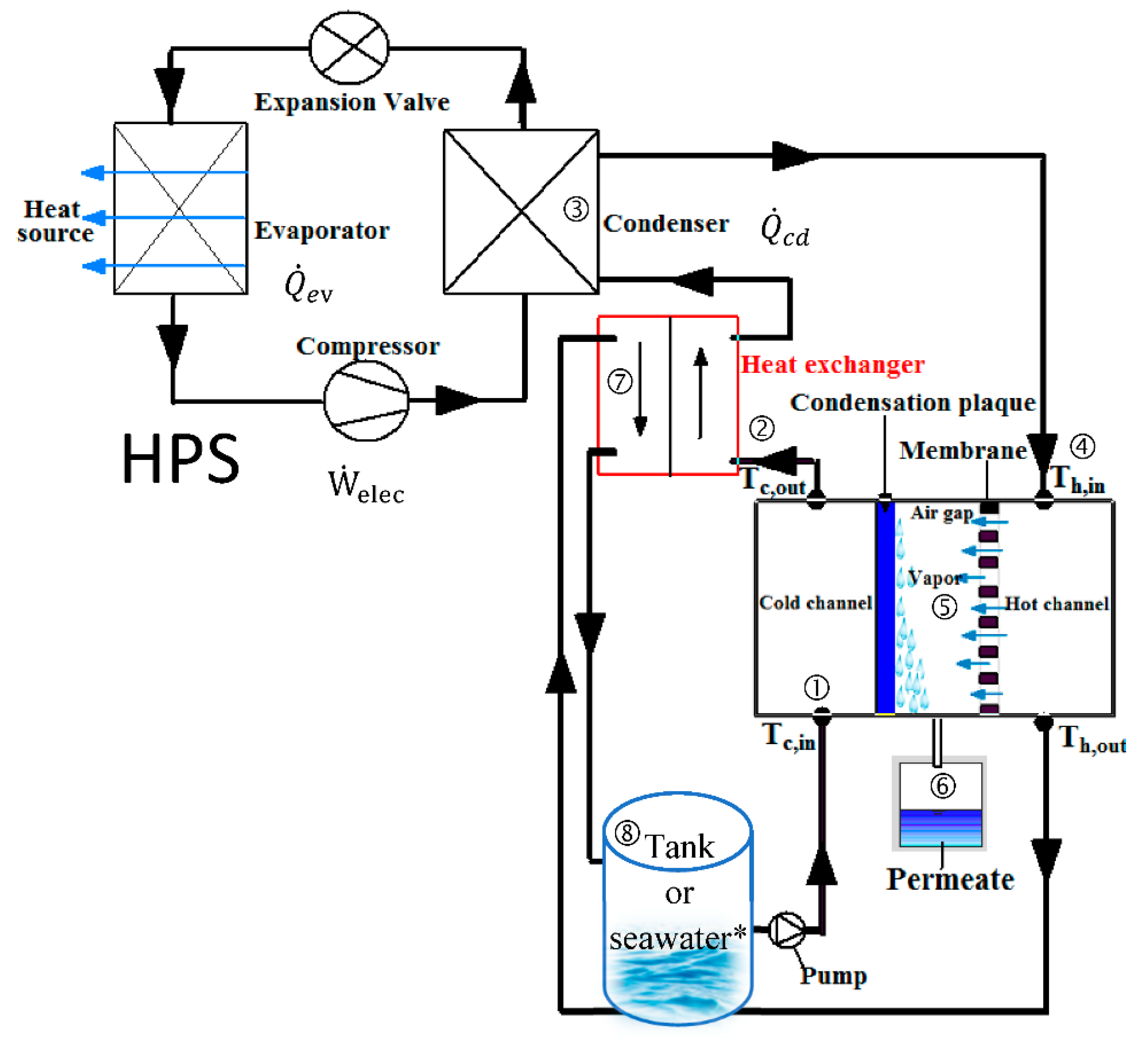
  • Entry of seawater into the cold channel to cool the condensation plate.
  • Preheating by the heat of the brine, provided by an internal exchanger.
  • Heats to the set temperature thanks to the condensation of the refrigerant from the HPS.
  • Entering the hot channel.
  • Evaporation of pure water at the membrane surface, vapor transfer then condensation on the cold plate.
  • Collecting of the permeate.
  • Reuse the brine for preheating in the internal exchanger.
  • Discharge of the brine into a tank or directly into the sea depending on the application (symbol * in the figure).
Another article published in the International Journal of Refrigeration deals with the simulation of heat pumps for simultaneous cooling and desalination using CO2 [40]. Table 13 synthetizes the results of the two previous publications [9,40]. The CO2 transcritical cycle enables a large variation of the seawater temperature. Exergy efficiencies with CO2 are lower because of high temperature variation but the specific energy consumption is reduced by around 4-fold.
A prototype was built and tested. An experimental parametric study was carried out [116]. The two main varied parameters were the flow rate and the temperature of the water entering the system. The tests confirmed that the inlet temperature of the hot channel and the circulation rate of the hot water supply have a significant effect on the permeate flow and that the effect of the temperature of the coolant is not negligible. This study also highlighted the effects of couplings between the two productions. Decreasing the hot water flow increases the circulation time in the condenser. This has the effect of increasing the temperature of the warm seawater and the condensing temperature of the thermodynamic cycle of the TFP. The COP is therefore reduced, and the mass of distilled water produced should increase.
Bindels and Nelemans recently developed an ammonia heat pump coupled to a vacuum-assisted air gap membrane distillation system [117]. The lowest SEC theoretically achieved is 9 kWhelec/m3. The system also enables to propose a zero liquid discharge operating configuration. They tested a 500 kW thermal power unit producing a permeate flux of around 6 l·m−2·h−1, corresponding to 100 m3/day, and worked on the cost of water reduction using the variability of electricity prices [118].
Finally, on a larger scale, the other application of combining production of heat, cold and mechanical work was studied by Liu et al. [119] and Mohammadi and Powell [120]. Thermodynamic cycles differ from vapor compression cycles in that they are generally motor and include expansion in an expander. Carbon dioxide is a fluid with privileged thermophysical properties for this type of operation. Due to its low temperature at the critical point, large pressure differences are observed over the cycle and therefore a high mechanical work can be obtained on expansion. A parametric study was carried out by our research group on a long-duration energy storage using pumped-hydro and carbon dioxide transcritical cycles as a heat pump [121]. This application affects more the industrial sector in which buildings also demand high amounts of heating and cooling energies.

6. Conclusions

The environmental context of climate change and the scarcity of resources tends to favor more the hybridization of systems as an effective solution to reduce energy consumption. Heat pumps for simultaneous heating and cooling (HPSs) are multi-energy systems. Heat recovery in the refrigeration industry is currently growing. Heat pumps can also be used for several buildings having different thermal demands in order to increase the need for simultaneous production. This configuration implies the organization of a collective supply with an individualized billing process.
According to the literature review of patents and scientific articles, HPSs are generally unique systems for heating, cooling and DHW production, designed for a specific application and with quite high power, used in large buildings or in targeted industrial processes. All studies show an improvement in performance compared to systems producing only one energy type. However, HPSs are inherently more complex. It is this complexity that explains why they have not yet become democratized. More components need to be connected and well controlled. All systems have an automatic control to manage the different operating modes and the temperatures or flow rates of the source fluids. The free balancing sources are, more generally, the outside air, a geothermal well, a water loop or gray water. Optimizations regarding refrigeration cycles, refrigerants, circuit architectures and technological components were carried out on various aspects and still need to be conducted in order to continue to promote and disseminate the hybrid efficient systems that are heat pumps for simultaneous heating and cooling.

Funding

This research received funding from BPO (Banque Populaire de l’Ouest) and Région Bretagne.

Conflicts of Interest

The authors declare no conflict of interest.

Nomenclature

Abbreviations
CFCchlorofluorocarbon
DHWdomestic hot water
ECBCSEnergy Conservation in Building Community Systems
EESEngineering Equation Solver
HChydrocarbon
HCFChydrochlorofluorocarbon
HFChydrofluorocarbon
HFOhydrofluoroolefin
HPSheat pump for simultaneous heating and cooling
IEAInternational Energy Agency
MDmembrane distillation
PEprimary energy
REenvironmental regulation
RTthermal regulation
TFAtrifluoroacetic acid
TRNSYSTransient System Simulation Software
Latin letters
crelative clearance volume (-)
COPcoefficient of performance (-)
Cpspecific heat (J·kg−1·K−1)
Eenergy consumption (kWh)
Exexergy (J)
exspecific exergy (J·kg−1)
Ex ˙ exergy rate (W)
ExRexergy ratio (kg·MJ−1)
ggravitational acceleration (m·s−2)
GORgained output ratio (-)
GWPGlobal Warming Potential (kgCO2 equivalent over a 100-year horizon)
hspecific enthalpy (kJ·kg−1)
HPhigh pressure (Pa), (bar)
kpolytropic coefficient (-)
Lannual leakage rate (%·an−1)
LELlower explosive limit (%)
LPlow pressure (Pa), (bar)
mmass (kg)
m ˙ mass flow rate (kg·s−1)
nlifetime (years), number of moles (mol)
ODPozone depletion potential (-)
Ppressure (Pa)
PRperformance ratio (kg·MJ−1)
Qheat amount (J)
Q ˙ thermal capacity (W)
Sentropy (J·K−1)
sspecific entropy (J·kg−1·K−1)
SCOPseasonal COP (-)
SECspecific energy consumption (kWh·m−3)
Ttemperature (K), (°C)
ttime (s)
TEWItotal equivalent warming impact (kgCO2)
tttotal time (s)
Uinternal energy (J)
uvelocity (m·s−1)
UELupper explosive limit (%)
Vvolume (m3)
vspecific volume (m3·kg−1)
Vsweptswept volume (m3·s−1)
W ˙ mechanical power (W)
zaltitude (m)
Greek letters
αrecovery rate (%)
βgreenhouse gas emission ratio (kgCO2·kWh−1)
Δdiscrepancy
ηefficiency (-)
μi0chemical potential (J·mol−1)
ρdensity (kg·m−3)
Subscripts
0reference state
ambambient
auxauxiliaries
ccooling
cwcold water
CDcondenser
cdcondensation
chchemical
CPcompressor
critcritical
Ddestructed
ecoeconomical
elecelectric
EVevaporator
evevaporation
EXexpansion valve
exexergetic
gcgas cooler
hheating
h&cheating and cooling
hwhot water
ininternal, inlet
isisentropic
kinkinetic
mecamechanical
optoptimal
outoutlet
phphysical
potpotential
proprocess
sosource
ththermal
vapvaporization
volvolumetric
wwater
wmwithout movement

References

  1. Agence de l’Environnement et de la Maîtrise de l’Energie. Climat, Air et Energie—Chiffres-Clés; ADEME: Montrouge, France, 2015. [Google Scholar]
  2. Pardiñas, Á.Á.; Jokiel, M.; Schlemminger, C.; Selvnes, H.; Hafner, A. Modeling of a CO2-Based Integrated Refrigeration System for Supermarkets. Energies 2021, 14, 6926. [Google Scholar] [CrossRef]
  3. Byrne, P. Advances in air-source heat pump water heaters. In Novel Concepts for Energy-Efficient Water Heating Systems. Theoretical Analysis and Experimental Investigation; Barbin, D.F., Silveira, V., Eds.; Nova Science Publishers: Hauppauge, NY, USA, 2013; Chapter 4; pp. 93–122. [Google Scholar]
  4. Byrne, P.; Ghoubali, R.; Miriel, J. Scroll compressor modelling for heat pumps using hydrocarbons as refrigerants. Int. J. Refrig. 2014, 41, 1–13. [Google Scholar] [CrossRef] [Green Version]
  5. Dincer, I.; Cengel, Y.A. Energy, entropy and exergy concepts and their roles in thermal engineering. Entropy 2001, 3, 116–149. [Google Scholar] [CrossRef]
  6. Torío, H.; Angelotti, A.; Schmidt, D. Exergy analysis of renewable energy-based climatisation systems for buildings: A critical view. Energy Build. 2009, 41, 248–271. [Google Scholar] [CrossRef]
  7. Dincer, I.; Rosen, M.A. Exergy Analysis of Heating, Refrigerating and Air Conditioning: Methods and Applications. In Exergy and Its Ties to the Environment, Economics, and Sustainability; Elsevier: Amsterdam, The Netherlands, 2015; Chapter 1; pp. 1–42. [Google Scholar]
  8. Ahamed, J.U.; Saidur, R.; Masjuki, H.H. A review on exergy analysis of vapor compression refrigeration system. Renew. Sustain. Energy Rev. 2011, 15, 1593–1600. [Google Scholar] [CrossRef]
  9. Diaby, A.T.; Byrne, P.; Loulergue, P.; Balannec, B.; Szymczyk, A.; Mare, T.; Sow, O. Design study of the coupling of an air gap membrane distillation unit to an air conditioner. Desalination 2017, 420, 308–317. [Google Scholar] [CrossRef]
  10. Byrne, P.; Ghoubali, R. Exergy analysis of heat pumps for simultaneous heating and cooling. Appl. Therm. Eng. 2019, 149, 414–424. [Google Scholar] [CrossRef]
  11. Morosuk, T.; Tsatsaronis, G. Advanced exergetic evaluation of refrigeration machines using different working fluids. Energy 2009, 34, 2248–2258. [Google Scholar] [CrossRef]
  12. Byrne, P.; Diaby, A.T.; Ghoubali, R.; Maré, T.; Sow, O. Fluides frigorigènes naturels et fluides a faible GWP pour petites pompes à chaleur. In Proceedings of the Colloque Interuniversitaire Franco-Québécois, CIFQ 2017, Saint-Lô, France, 22–24 May 2017. [Google Scholar]
  13. ANSI/ASHRAE Standard 34; Designation and Safety Classification of Refrigerants. American Society of Heating, Refrigerating and Air-Conditioning Engineers: Atlanta, GA, USA, 2004.
  14. AFNOR, NF EN 378-1; Systèmes de réfrigération et pompes à chaleur—Exigences de sécurité et d’environnement—Partie 1: Exigences de base, définitions, classification et critères de choix. Afnor EDITIONS: Saint-Denis, France, 2012.
  15. Directive 2014/68/UE; du Parlement Européen et du Conseil du 15 mai 2014 relative à l’Harmonisation des léGislations des États Membres Concernant la Mise à Disposition sur le Marché des éQuipements Sous Pression. European Union: Brussels, Belgium, 2014.
  16. IEC 60335; Household and Similar Electrical Appliances—Safety. International Electrotechnical Commission: Geneva, Switzerland, 2002.
  17. Granryd, E. Hydrocarbons as refrigerants—An overview. Int. J. Refrig. 2001, 24, 15–24. [Google Scholar] [CrossRef]
  18. Palm, B. Hydrocarbons as refrigerants in small heat pump and refrigeration systems—A review. Int. J. Refrig. 2008, 31, 552–563. [Google Scholar] [CrossRef]
  19. Corberan, J.M.; Segurado, J.; Colbourne, D.; Gonzalvez, J. Review of standards for the use of hydrocarbon refrigerants in A/C, heat pump and refrigeration equipement. Int. J. Refrig. 2008, 31, 748–756. [Google Scholar] [CrossRef]
  20. Guilpart, J. Evaluation des risques liés aux fluides frigorigènes naturels. Tech. L’Ingénieur 1999, BE9750, 19. [Google Scholar] [CrossRef]
  21. Claret, J.C. Retour D’expérience: L’ammoniac et La Réfrigeration; SEI/BARPIED00389; Ministère de L’environnement, Service de L’environnement Industriel: Paris, France, 1995.
  22. Islam, M.A.; Srinivasan, K.; Thu, K.; Saha, B.B. Assessment of total equivalent warming impact (TEWI) of supermarket refrigeration systems. Int. J. Hydrogen Energy 2017, 42, 26973–26983. [Google Scholar] [CrossRef]
  23. Davies, T.W.; Caretta, O. A low carbon, low TEWI refrigeration system design. Appl. Therm. Eng. 2004, 24, 1119–1128. [Google Scholar] [CrossRef]
  24. Cavallini, A. Working fluids for mechanical refrigeration. Invited paper at the 19th International Congress of Refrigeration, The Hague, August 1995. Int. J. Refrig. 1996, 19, 485–496. [Google Scholar] [CrossRef]
  25. Llopis, R.; Calleja-Anta, D.; Maiorino, A.; Nebot-Andrés, L.; Sánchez, D.; Cabello, R. TEWI analysis of a stand-alone refrigeration system using low-GWP fluids with leakage ratio consideration. Int. J. Refrig. 2020, 118, 279–289. [Google Scholar] [CrossRef]
  26. European Commission. Regulation (EU) No 517/2014: On Fluorinated Greenhouse Gases and Repealing Regulation (EC) No 842/2006; Official Journal of European Union: Brussels, Belgium, 2014. [Google Scholar]
  27. UNEP. The Kigali Amendment to the Montreal Protocol: HFC Phase-down; Ozone Action Fact Sheet United Nations Environment Program (UNEP): Nairobi, Kenya, 2016; pp. 1–7. [Google Scholar]
  28. Réseau Action Climat France. Available online: http://www.rac-f.org (accessed on 28 March 2022).
  29. Navarro-Esbri, J.; Mendoza-Miranda, J.M.; Mota-Babiloni, A.; Barragan-Cervera, A.; Belman-Flores, J.M. Experimental analysis of R1234yf as a drop-in replacement for R134a in a vapor compression system. Int. J. Refrig. 2013, 36, 870–880. [Google Scholar] [CrossRef]
  30. Zilio, C.; Brown, J.S.; Schiochet, G.; Cavallini, A. The refrigerant R1234yf in air conditioning systems. Energy 2011, 36, 6110–6120. [Google Scholar] [CrossRef]
  31. Lee, Y.; Jung, D. A brief performance comparison of R1234yf and R134a in a bench tester for automobile applications. Appl. Therm. Eng. 2012, 35, 240–242. [Google Scholar] [CrossRef]
  32. Henne, S.; Shallcross, D.E.; Reimann, S.; Xiao, P.; Brunner, D.; O’Doherty, S.; Buchmann, B. Future emissions and atmospheric fate of HFC-1234yf from mobile air conditioners, in Europe. Environ. Sci. Technol. 2012, 46, 1650–1658. [Google Scholar] [CrossRef]
  33. Fukuda, S.; Kondou, C.; Takata, N.; Koyama, S. Low GWP refrigerants R1234ze(E) and R1234ze(Z)for high temperature heat pumps. Int. J. Refrig. 2014, 40, 161–173. [Google Scholar] [CrossRef]
  34. Calm, J.M. Emissions and environmental impacts from air-conditioning and refrigeration systems. Int. J. Refrig. 2002, 25, 293–305. [Google Scholar] [CrossRef]
  35. Duminil, M. Histoire et Evolution des Fluides Frigorigènes des Systèmes Frigorifiques à Compression. Rev. GÉNÉRale Du Froid Du Cond. d’Air 2008, 1080, 45–55. [Google Scholar]
  36. Chang, Y.S.; Kim, M.S.; Ro, S.T. Performance and heat transfer characteristics of hydrocarbon refrigerants in a heat pump system. Int. J. Refrig. 2000, 23, 232–242. [Google Scholar] [CrossRef]
  37. Liao, S.M.; Zhao, T.S.; Jakobsen, A. A correlation of optimal pressures in transcritical carbon dioxide cycles. Appl. Therm. Eng. 2000, 20, 831–841. [Google Scholar] [CrossRef]
  38. Byrne, P.; Miriel, J.; Lénat, Y. Design and simulation of a heat pump for simultaneous heating and cooling using HFC or CO2 as a working fluid. Int. J. Refrig. 2009, 32, 1711–1723. [Google Scholar] [CrossRef] [Green Version]
  39. Yang, L.; Li, H.; Cai, S.W.; Shao, L.L.; Zhang, C.L. Minimizing COP loss from optimal high pressure correlation for transcritical CO2 cycle. Appl. Therm. Eng. 2015, 89, 656–662. [Google Scholar] [CrossRef]
  40. Diaby, A.T.; Byrne, P.; Mare, T. Simulation of heat pumps for simultaneous heating and cooling using CO2. Int. J. Refrig. 2019, 106, 616–627. [Google Scholar] [CrossRef]
  41. Qi, P.C.; He, Y.L.; Wang, X.L.; Meng, X.Z. Experimental investigation of the optimal heat rejection pressure for a transcritical CO2 heat pump water heater. Appl. Therm. Eng. 2013, 56, 120–125. [Google Scholar] [CrossRef]
  42. Lorentzen, G. Revival of Carbon Dioxide as a Refrigerant. Int. J. Refrig. 1994, 17, 292–301. [Google Scholar] [CrossRef]
  43. Neksa, P. CO2 Heat Pump Systems. Int. J. Refrig. 2002, 25, 421–427. [Google Scholar] [CrossRef]
  44. Kusakari, K. The spread situation and the future view of the CO2 refrigerant heat pump water heater in Japan. In Proceedings of the 7th IIR Gustav Lorentzen Conference on Natural Working Fluids, Trondheim, Norway, 29–31 May 2006. [Google Scholar]
  45. Stene, J. Residential CO2 heat pump system for combined space heating and hot water heating. Int. J. Refrig. 2005, 28, 1259–1265. [Google Scholar] [CrossRef] [Green Version]
  46. Fournaison, L. Evolution des Fluides Frigoporteurs. Rev. Générale Du Froid Du Cond. d’Air 2008, 1080, 45–55. [Google Scholar]
  47. AFNOR, NF EN 14511-3; Climatiseurs, Groupes Refroidisseurs de Liquide et Pompes à Chaleur Avec Compresseur Entraîné par Moteur éLectrique Pour le Chauffage et la Réfrigération. Partie 3: Méthodes D’Essai. Afnor EDITIONS: Saint-Denis, France, 2004.
  48. AFNOR, NF EN 16147; Pompes à Chaleur Avec Compresseur Entraîné Par Moteur Électrique—Essais, Détermination Des Performances et Exigences Pour le Marquage Des Appareils Pour eau Chaude Sanitaire. Afnor EDITIONS: Saint-Denis, France, 2017.
  49. Klein, S. Engineering Equation Solver, Version 10.200-3D, ©1992–2017; F-Chart Software: Madison, WI, USA, 2017. [Google Scholar]
  50. Technical University of Denmark, Department of Mechanical Engineering. Coolpack, A Collection of Simulation Tools for Refrigeration (1997–2001); Technical University of Denmark: Lyngby, Denmark, 2001. [Google Scholar]
  51. Stabat, P. Analysis of Heating and Cooling Demands in the Purpose of Assessing the Reversibility and Heat Recovery Potentials, IEA EBC Annex 48 Project Report R1. 2011. Available online: https://www.iea-ebc.org/Data/publications/EBC_Annex_48_Final_Report_R1.pdf (accessed on 28 March 2022).
  52. Bertagnolio, S.; Stabat, P. Review of Heat Recovery and Heat Pumping Solutions, IEA EBC Annex 48 Project Report R2. 2011. Available online: https://www.iea-ebc.org/Data/publications/EBC_Annex_48_Final_Report_R2.pdf (accessed on 28 March 2022).
  53. Ghoubali, R.; Byrne, P.; Miriel, J.; Bazantay, F. Simulation study of heat pumps for simultaneous heating and cooling coupled to buildings. Energy Build. 2014, 72, 141–149. [Google Scholar] [CrossRef] [Green Version]
  54. Byrne, P.; Miriel, J.; Lénat, Y. Modelling and simulation of a heat pump for simultaneous heating and cooling. Build.Simul. Int. J. 2012, 5, 219–232. [Google Scholar] [CrossRef] [Green Version]
  55. Klein, S. TRNSYS 17: A Transient System Simulation Program, Solar Energy Laboratory; University of Wisconsin: Madison, WI, USA, 2010; Available online: http://sel.me.wisc.edu/TRNSYS (accessed on 28 March 2022).
  56. Recknagel, H.; Sprenger, E.; Schramek, E.R. Recknagel, Manuel Pratique du Génie Climatique: Chauffage et Production d’eau Chaude Sanitaire; PYC Edition: Paris, France, 1996; p. 222. [Google Scholar]
  57. AICVF. Association des Ingénieurs en Climatique, Ventilation et Froid. Volume 6, Bâtiments Non réSidentiels; AICVF: Paris, France, 2000. [Google Scholar]
  58. Byrne, P.; Fournaison, L.; Delahaye, A.; Ait Oumeziane, Y.; Serres, L.; Loulergue, P.; Szymczyk, A.; Mugnier, D.; Malaval, J.-L.; Bourdais, R.; et al. A review on the coupling of cooling, desalination and solar photovoltaic systems. Renew. Sustain. Energy Rev. 2015, 47, 703–717. [Google Scholar] [CrossRef]
  59. Hunt, J.D.; de Assis Brasil Weber, N.; Zakeri, B.; Diaby, A.T.; Byrne, P.; Leal Filho, W.; Smith Schneider, P. Deep seawater cooling and desalination: Combining seawater air conditioning and desalination. Sustain. Cities Soc. 2021, 74, 103257. [Google Scholar] [CrossRef]
  60. Zimmerman, W.G. Heating and Cooling Air Conditioning System. U.S. Patent 2,581,744, 8 January 1952. [Google Scholar]
  61. Harnish, J.R.; Westinghouse Electric Corporation. Heat Pumps for Simultaneous Cooling and Heating. U.S. Patent 3,264,839, 9 August 1966. [Google Scholar]
  62. Yamazaki, K.; Otsubo, M.; Okuma, K.; Mitsubishi Electric Corp. Room-Warming/Cooling and Hot-Water Supplying Heat-Pump Apparatus. U.S. Patent 4,592,206, 3 June 1986. [Google Scholar]
  63. Matsuura, T.; Union Kogyo Kabushiki Kaisha. Apparatus and Method for Heating and Cooling with a Refrigerant. U.S. Patent 5,211,023, 18 May 1993. [Google Scholar]
  64. Jungwirth, C.A. Apparatus for Simultaneous Heating Cooling and Humidity Removal. U.S. Patent 6,751,972, 22 June 2004. [Google Scholar]
  65. Leballais, H.; CLIMATIK Sarl. Heating and Refrigerating System for e.g., Room of Building, Has Auxiliary Exchanger Connected to Loop and Operating in Condensing Mode in Place of Condenser or in Evaporating Mode in Place of Evaporator. F.R. Patent 2,886,388, 26 October 2007. [Google Scholar]
  66. Moreau, C. Mobile Confort Holding. Multi-Energy Thermodynamic Device with Simultaneous Production of Hot Water, Warm Water, Cold Water and Electricity. E.P. Patent 2,085,721, 5 August 2009. [Google Scholar]
  67. Ghoubali, R.; Bazantay, F.; Méar, L.; Miriel, J.; Byrne, P. Refrigerating Circuit, Facility Comprising such a Circuit and Corresponding Method. Patent WO2015/015104A1, 5 February 2015. [Google Scholar]
  68. Marnet, P.; Mantran, B.; Mallet, J.A.; Rybaka, R. La Centrale Thermodynamique de la Maison de l’ORTF, Application à la Climatisation; Annales de l’Institut Technique du Bâtiment et des Travaux Publics: Paris, France, 1964; p. 204. [Google Scholar]
  69. Le Goff, P. Exergetic, economic or ecologic optimisations of heat-cold-pumps. Entropie 1999, 220–221, 6–11. [Google Scholar]
  70. Lecrivain, E.; Laroche, G.; Vallot, A. La production simultanée d’eau glacée et d’eau chaude à 95 °C par une thermofrigopompe d’une laiterie. Int. J. Refrig. 1982, 5, 221–225. [Google Scholar] [CrossRef]
  71. Ghosh, V.S.; Devotta, S.; Patwardhan, S. The economics of heat pump systems for simultaneous heating and cooling. Heat Recovery Syst. 1987, 7, 159–166. [Google Scholar] [CrossRef]
  72. Naveteur, J.; Bruss, C. Chauffage et Rafraîchissement de la CAF de Lyon: Une Réussite Exemplaire! Rev. GÉNÉRale Du Froid Du Cond. d’Air 2007, 1079, 23–26. [Google Scholar]
  73. CFP. La «Thermofrigopompe», une technique économe… et peu émettrice de CO2. Chaud Froid Plomb. 2001, 632, 67–71. [Google Scholar]
  74. CFP. Un immeuble parisien climatisé par une thermofrigopompe sur nappe phréatique. Chaud Froid Plomb. 2003, 660, 62–68. [Google Scholar]
  75. Wesser, S.; Haëntjens, H. Systèmes à eau: Rendements optimisés grâce à la nappe. Clim Prat. 2006, 76, 49–53. [Google Scholar]
  76. MAD. Climatisation d’Infogrames par Thermofrigopompes. MAD l’Outil. Froid 2002, 47, 32–37. [Google Scholar]
  77. Bouttefroy, P. Thermofrigopompe chez IBM Corbeil. Rev. GénéRale Du Froid 1990, 6, 19–23. [Google Scholar]
  78. White, S.D.; Cleland, D.J.; Cotter, S.D.; Stephenson, R.A.; Kallu, R.D.S.; Fleming, A.K. A heat pump for simultaneous refrigeration and water heating. In IPENZ Transactions 1997; Engineers New Zealand: Wellington, New Zealand, 1997; Volume 24, No. 1/EMCh. [Google Scholar]
  79. Sappa, F. Chaud et Froid à l’Infirmerie protestante. Clim Prat. 2003, 52, 30–32. [Google Scholar]
  80. Haëntjens, H. Système à eau: Ayphassorho Met l’Exergy en Musique. Clim Prat. 2006, 76, 55–58. [Google Scholar]
  81. Gong, G.; Zeng, W.; Wang, L.; Wu, C. A new heat recovery technique for air-conditioning/heat-pump system. Appl. Therm. Eng. 2008, 28, 2360–2370. [Google Scholar] [CrossRef]
  82. Gong, G.; Chen, F.; Su, H.; Zhou, J. Thermodynamic simulation of condensation heat recovery characteristics of a single stage centrifugal chiller in a hotel. Appl. Energy 2012, 91, 326–333. [Google Scholar] [CrossRef]
  83. Sarkar, J.; Bhattacharyya, S.; Gopal, M.R. Optimization of a transcritical CO2 heat pump cycle for simultaneous cooling and heating applications. Int. J. Refrig. 2004, 27, 830–838. [Google Scholar] [CrossRef]
  84. Sarkar, J.; Bhattacharyya, S.; Gopal, M.R. Simulation of a transcritical CO2 heat pump cycle for simultaneous cooling and heating applications. Int. J. Refrig. 2006, 29, 735–743. [Google Scholar] [CrossRef]
  85. Sarkar, J.; Bhattacharyya, S.; Gopal, M.R. Performance of a Transcritical CO2 heat pump for simultaneous water cooling and Heating. Int. J. Mech. Mechatron. Eng. 2010, 4, 571–577. [Google Scholar]
  86. Fatouh, M.; Elgendy, E. Experimental investigation of a vapor compression heat pump used for cooling and heating applications. Energy 2011, 36, 2788–2795. [Google Scholar] [CrossRef]
  87. Agrawal, N.; Bhattacharyya, S. Experimental investigations on adiabatic capillary tube in a transcritical CO2 heat pump system for simultaneous water cooling and heating. Int. J. Refrig. 2011, 34, 476–483. [Google Scholar] [CrossRef]
  88. Liu, X.; Ni, L.; Lau, S.; Li, H. Performance analysis of a multi-functional heat pump system in heating mode. Appl. Therm. Eng. 2013, 51, 698–710. [Google Scholar] [CrossRef]
  89. Liu, X.; Lau, S.K.; Li, H. Optimization and analysis of a multi-functional heat pump system with air source and gray water source in heating mode. Energy Build. 2014, 69, 1–13. [Google Scholar] [CrossRef]
  90. Kang, H.; Joo, Y.; Chung, H.; Kim, Y.; Choi, J. Experimental study on the performance of a simultaneous heating and cooling multi-heat pump with the variation of operation mode. Int. J. Refrig. 2009, 32, 1452–1459. [Google Scholar] [CrossRef]
  91. Joo, Y.; Kang, H.; Ahn, J.H.; Lee, M.; Kim, Y. Performance characteristics of a simultaneous cooling and heating multi-heat pump at partial load conditions. Int. J. Refrig. 2011, 34, 893–901. [Google Scholar] [CrossRef]
  92. Jung, H.W.; Kang, H.; Chung, H.; Ahn, J.H.; Kim, Y. Performance optimization of a cascade multi-functional heat pump in various operation modes. Int. J. Refrig. 2014, 42, 57–68. [Google Scholar] [CrossRef]
  93. Boahen, S.; Anka, S.K.; Lee, K.H.; Choi, J.M. Performance characteristics of a cascade multi-functional heat pump in the winter season. Energy Build. 2021, 253, 111511. [Google Scholar] [CrossRef]
  94. Fricker, J.; Zoughaib, A. Simultaneous heating and cooling production devices composed by reverse cycle systems under variable loads. Int. J. Refrig. 2015, 55, 1–16. [Google Scholar] [CrossRef]
  95. Liu, Y.; Groll, E.A.; Yazawa, K.; Kurtulus, O. Theoretical analysis of energy-saving performance and economics of CO2 and NH3 heat pumps with simultaneous cooling and heating applications in food processing. Int. J. Refrig. 2016, 65, 129–141. [Google Scholar] [CrossRef]
  96. Liu, Y.; Groll, E.A.; Yazawa, K.; Kurtulus, O. Energy-saving performance and economics of CO2 and NH3 heat pumps with simultaneous cooling and heating applications in food processing: Case studies. Int. J. Refrig. 2017, 73, 111–124. [Google Scholar] [CrossRef]
  97. Yang, Y.; Xie, X.; Jiang, Y. Novel beverage heating and fast-cooling processes separately using an absorption chiller and using electric heat pumps. Int. J. Refrig. 2018, 94, 87–101. [Google Scholar] [CrossRef]
  98. Shin, D.U.; Ryu, S.R.; Kim, K.W. Simultaneous heating and cooling system with thermal storage tanks considering energy efficiency and operation method of the system. Energy Build. 2019, 205, 109518. [Google Scholar] [CrossRef]
  99. Deymi-Dashtebayaz, M.; Namanlo, S.V.; Arabkoohsar, A. Simultaneous use of air-side and water-side economizers with the air source heat pump in a data center for cooling and heating production. Appl. Therm. Eng. 2019, 161, 114133. [Google Scholar] [CrossRef]
  100. Best, R.; Eisa, M.A.R.; Holland, F.A. Thermodynamic design data for absorption heat pump systems operating on ammonia-water—Part III. Simultaneous cooling and heating. Heat Recovery Syst. CHP 1987, 7, 187–194. [Google Scholar] [CrossRef]
  101. Zheng, X.; Shi, R.; Wang, Y.; You, S.; Zhang, H.; Xia, J.; Wei, S. Mathematical modeling and performance analysis of an integrated solar heating and cooling system driven by parabolic trough collector and double-effect absorption chiller. Energy Build. 2019, 202, 109400. [Google Scholar] [CrossRef]
  102. Wang, J.; Belusko, M.; Liu, M.; Semsarilar, H.; Liddle, R.; Alemu, A.; Evans, M.; Zhao, C.; Hudson, J.; Bruno, F. A comprehensive study on a novel transcritical CO2 heat pump for simultaneous space heating and cooling—Concepts and initial performance. Energy Convers. Manag. 2021, 243, 114397. [Google Scholar] [CrossRef]
  103. Artuso, P.; Tosato, G.; Rossetti, A.; Marinetti, S.; Hafner, A.; Banasiak, K.; Minetto, S. Dynamic Modelling and Validation of an Air-to-Water Reversible R744 Heat Pump for High Energy Demand Buildings. Energies 2021, 14, 8238. [Google Scholar] [CrossRef]
  104. Shin, D.-U.; Jeong, C.-H. Energy Savings of Simultaneous Heating and Cooling System According to Indoor Set Temperature Changes in the Comfort Range. Energies 2021, 14, 7691. [Google Scholar] [CrossRef]
  105. Byrne, P.; Miriel, J.; Lénat, Y. Experimental study of a heat pump for simultaneous heating and cooling—Part 1: Basic concepts and performance verification. Appl. Energy 2011, 88, 1841–1847. [Google Scholar] [CrossRef] [Green Version]
  106. Byrne, P.; Miriel, J.; Lénat, Y. Experimental study of an air-source heat pump for simultaneous heating and cooling—Part 2: Dynamic behaviour and two-phase thermosiphon defrosting technique. Appl. Energy 2011, 88, 3072–3078. [Google Scholar] [CrossRef] [Green Version]
  107. Ahrens, M.U.; Foslie, S.S.; Moen, O.M.; Bantle, M.; Eikevik, T.M. Integrated high temperature heat pumps and thermal storage tanks for combined heating and cooling in the industry. Appl. Therm. Eng. 2021, 189, 116731. [Google Scholar] [CrossRef]
  108. Al-Sayyab, A.K.S.; Mota-Babiloni, A.; Navarro-Esbrí, J. Novel compound waste heat-solar driven ejector-compression heat pump for simultaneous cooling and heating using environmentally friendly refrigerants. Energy Convers. Manag. 2021, 228, 113703. [Google Scholar] [CrossRef]
  109. Al-Sayyab, A.K.S.; Navarro-Esbrí, J.; Mota-Babiloni, A. Energy, exergy, and environmental (3E) analysis of a compound ejector-heat pump with low GWP refrigerants for simultaneous data center cooling and district heating. Int. J. Refrig. 2022, 133, 61–72. [Google Scholar] [CrossRef]
  110. Calise, F.; Cappiello, F.L.; d’Accadia, M.D.; Petrakopoulou, F.; Vicidomini, M. A solar-driven 5th generation district heating and cooling network with ground-source heat pumps: A thermo-economic analysis. Sustain. Cities Soc. 2022, 76, 103438. [Google Scholar] [CrossRef]
  111. Quirosa, G.; Torres, M.; Solter, V.M.; Chacartegui, R. Energetic and economic analysis of decoupled strategy for heating and cooling production with CO2 booster heat pumps for ultra-low temperature district network. J. Build. Eng. 2022, 45, 103538. [Google Scholar] [CrossRef]
  112. Kong, R.; Deethayat, T.; Asanakham, A.; Kiatsiriroat, T. Performance and economic evaluation of a photovoltaic/thermal (PV/T)-cascade heat pump for combined cooling, heat and power in tropical climate area. J. Energy Storage 2020, 30, 101507. [Google Scholar] [CrossRef]
  113. Amin, Z.M.; Hawlader, M.N.A. Analysis of solar desalination system using heat pump. Renew. Energy 2015, 74, 116–123. [Google Scholar] [CrossRef]
  114. Attia, A.A.A. New proposed system for freeze water desalination using auto reversed R-22 vapor compression heat pump. Desalination 2010, 254, 179–184. [Google Scholar] [CrossRef]
  115. Koschikowski, J.; Wieghaus, M.; Rommel, M. Solar thermal-driven desalination plants based on membrane distillation. Desalination 2003, 156, 295–304. [Google Scholar] [CrossRef]
  116. Diaby, A.T.; Byrne, P.; Loulergue, P.; Sow, O.; Maré, T. Experimental Study of a Heat Pump for Simultaneous Cooling and Desalination by Membrane Distillation. Membranes 2021, 11, 725. [Google Scholar] [CrossRef]
  117. Bindels, M.; Nelemans, B. Theoretical analysis of heat pump assisted air gap membrane distillation. Desalination 2021, 518, 115282. [Google Scholar] [CrossRef]
  118. Bindels, M.; Nelemans, B. Cost reduction of heat pump assisted membrane distillation by using variable electricity prices. Desalination 2022, 530, 115669. [Google Scholar] [CrossRef]
  119. Liu, Z.; Cao, F.; Guo, J.; Liu, J.; Zhai, H.; Duan, Z. Performance analysis of a novel combined cooling, heating and power system based on carbon dioxide energy storage. Energy Convers. Manag. 2019, 188, 151–161. [Google Scholar] [CrossRef]
  120. Mohammadi, K.; Powell, K. Thermodynamic and economic analysis of different cogeneration and trigeneration systems based on carbon dioxide vapor compression refrigeration systems. Appl. Therm. Eng. 2020, 164, 114503. [Google Scholar] [CrossRef]
  121. Byrne, P.; Lalanne, P. Parametric Study of a Long-Duration Energy Storage Using Pumped-Hydro and Carbon Dioxide Transcritical Cycles. Energies 2021, 14, 4401. [Google Scholar] [CrossRef]
Figure 1. “Real” heat pump cycle in the P-h diagram.
Energies 15 03529 g001
Figure 2. Scheme of the compressor modeling principles. Adapted with permission from Ref. [4]. 2014, Elsevier.
Energies 15 03529 g002
Figure 3. Classification of refrigerants with respect to their flammability and toxicity according to ASHRAE. Reprinted with permission from Ref. [13]. 2004, ASHRAE.
Energies 15 03529 g003
Figure 4. Drawing of the molecular structure of the two isomers of R1234ze; R1234ze(E) (left) and R1234ze(Z) (right).
Energies 15 03529 g004
Figure 5. CO2 transcritical cycle on the P-h diagram.
Energies 15 03529 g005
Figure 6. Comparison of optimal high pressures of the CO2 transcritical cycle calculated by four correlations.
Energies 15 03529 g006
Figure 7. Comparison of P-h diagrams.
Energies 15 03529 g007
Figure 8. Comparison of P-T diagrams.
Energies 15 03529 g008
Figure 9. Comparison of evolutions of specific heat depending on temperature.
Energies 15 03529 g009
Figure 10. Comparison of evolutions of thermal conductivity depending on temperature.
Energies 15 03529 g010
Figure 11. Comparison of evolutions of viscosity depending on temperature.
Energies 15 03529 g011
Figure 12. Comparison of cycle COPs in different operating modes.
Energies 15 03529 g012
Figure 13. Evolution of COPh&c for R134a and CO2 cycles depending on evaporating temperature.
Energies 15 03529 g013
Figure 14. Relationship between relative values of climate change, cooling degree days, solar resource and precipitation decrease per inhabitant of five cities.
Energies 15 03529 g014
Figure 15. Major coastal cities [59].
Energies 15 03529 g015
Figure 16. Major cities where CDD and PDPI are high [59].
Energies 15 03529 g016
Figure 17. Schematic diagram of the patent of Westinghouse Electric Corporation (US3264839).
Energies 15 03529 g017
Figure 18. Schematic diagram of the patent of Mitsubishi Denki Kabushiki Kaisha (US4592206).
Energies 15 03529 g018
Figure 19. Schematic diagram of the patent of Union Kogyo Kabushiki Kaisha (US5211023).
Energies 15 03529 g019
Figure 20. Schematic diagram of the patent of Jungwirth (US6751972).
Energies 15 03529 g020
Figure 21. Schematic diagram of the patent of Climatik Sarl (FR2886388-2005).
Energies 15 03529 g021
Figure 22. Schematic diagram of the patent of Mobile comfort holding (EP2085721).
Energies 15 03529 g022
Figure 23. First page of the patent of Ghoubali et al. [67].
Energies 15 03529 g023
Figure 24. Schematic diagram of the first HPS prototype.
Energies 15 03529 g024
Figure 25. Schematic diagram of a HPS coupled to a membrane distillation unit.
Energies 15 03529 g025
Table 1. Authorized charge in type A, B and C premises for direct systems.
RefrigerantHydrocarbon
Safety group (EN 378/1-2012/ASHRAE 34-2010)A3
Pressure Equipment Directive (2014/68/EU) [15]1
A—General occupation (residential, hotels, schools, etc.)<1.5 kg
B—Supervised occupation (offices, laboratories, manufacturing premises, etc.)1 kg below ground level and
2.5 kg above ground level
C—Occupancy only with restricted access (refineries, cold stores, etc.)1 kg below ground level and
10 kg above ground level
Table 2. Characteristics of HFCs R134a and R32.
FluidR134a
(1,1,1,2-Tetrafluoroethane)
R32
(Difluoromethane)
Chemical formulaC2H2F4CH2F2
GWP100years (kgCO2)1430650
ODP00
Potential risksClimate changeClimate change Flammability A2L
Table 3. Characteristics of HFOs R1234yf, R1234ze(E) and R1234ze(Z).
FluidR1234yf
(2,3,3,3-Tetrafluoroprop-1-ene)
R1234ze(E)
(Trans-1,3,3,3-Tétrafluoroprop-1-ene)
R1234ze(Z)
(Cis-1,3,3,3-Tétrafluoroprop-1-ene)
Chemical formulaCH2=CFCF3CFH=CH-CF3CFH=CH-CF3
GWP100years (kgCO2)47<10
ODP000
Potential risksSlight flammability
Water acidification
Slight flammability
Water acidification
Slight flammability
Water acidification
Table 4. Characteristics of ammonia.
FluidR717
(Ammoniac)
Chemical formulaNH3
GWP100years (kgCO2)0
ODP0
Potential risksHigh toxicity
Corrosion of copper
Slight flammability
Table 5. Application domains of hydrocarbons.
RefrigerantApplication DomainTemperature LevelsEquivalent Synthetized Fluid
R600a (isobutene)Domestic refrigerationHigh and middle temperature R12, R134a
R290 (propane)Commercial, industrial, freezers, air conditioning, heat pumpHigh, middle and low temperature R22, R404A, R407C, R507A
R1270 (propene)industrial refrigeration, air conditioning, heat pumps, tertiary, industrialHigh, middle and low temperature R22, R404A, R407C, R507A
Table 6. Characteristics of isobutene, propane and propene.
FluidR600a (Isobutene)R290 (Propane)R1270 (Propene)
Chemical formulaCH3CH2CH3C4H10C3H6
GWP100yeas (kgCO2)332
ODP000
Potential risksHigh flammability
LEL % (v/v)2.21.82
UEL % (v/v)109.811.2
Auto-ignition temperature470 °C460 °C485 °C
Table 7. Characteristics of carbon dioxide.
FluidR744
(Carbon Dioxide)
Chemical formulaCO2
GWP100years (kgCO2)1
ODP0
Potential risksHigh pressure
Table 8. Thermodynamic properties of the studied refrigerants.
RefrigerantMolar Mass (g/mol)Critical Temperature (°C)Critical Pressure (bar)Specific Volume at Tdew = 0 °C (m3/kg)Latent Heat at
Tdew = 0 °C (kJ/kg)
Latent Heat at
Tdew = 50 °C (kJ/kg)
R12120.90112.0041.140.05542151.5121.5
R2286.4796.1049.890.04708205.0154.1
R134a102.00101.0040.590.06925198.6151.8
R3252.0278.1057.840.04526315.3209.6
R407C86.2086.2046.320.05087218.2157.0
R1234yf114.0094.7033.820.05653163.3122.2
R1234ze(E)114.00109.4036.320.08389184.2145.1
R1234ze(Z)114.00150.1035.330.27900220.5189.0
R29044.1096.7042.470.09651374.7284.3
R600a58.12134.7036.400.23530355.0298.5
NH317.03132.30113.300.289201262.01050.0
CO244.0130.9873.770.01024230.9supercritical state
Table 9. Operating temperatures of simulated modes.
ModeTin,air (°C)Tout,air (°C)Tin,cw (°C)Tout,cw (°C)Tin,hw (°C)Tout,hw (°C)Tev (°C)Tcd (°C)
(1) heating only7−1--3035−640
(2) cooling only2735127--240
(3) DHW only7−1--1555−660
(4) simultaneous heating and cooling--1273035240
(5) simultaneous DHW and cooling--1271555260
Table 10. Simulation parameters for TRNSYS simulations.
Building TypeSurface
(m²)
Number of Thermal ZonesGains
OccupationLighting
(W/m²)
Number of Electrical Devices
(P = 230 W)
Number of PersonsHours
(a) Hotel144030Bedrooms: 45
Welcome zone: 3
20 h–7 h
8 h–18 h
10Welcome zone:
2
(b) Residential67515246 h–9 h
18 h–24 h
564
(c) Offices792121238 h–20 h10141
(d) Shop146751348 h–21 h109
Table 11. Average RSN values.
ClimateHotelResidentialOfficesShopShop with 730 kWh Commercial CoolingShop with 104 kWh Commercial Cooling
Oceanic18.97%28.00%28.17%10.17%7.64%26.82%
Continental15.31% *22.50%22.57%6.86%5.15%18.09%
Mediterranean20.47%30.52%24.37%10.26%7.71%27.06%
* Climate of Brussels.
Table 12. Annual simulation results obtained with TRNSYS.
ArticleBuildingSiteFluidPerformance IndexComments
[38] International Journal of RefrigerationHotelParisR407CSCOP = 3.57+16.7%Compared to a reversible heat pump
CO2SCOP = 3.26+20.7%
R407C η e x = 26.40%+11.0%
CO2 η e x = 27.48%+49.5%
R407CTEWI = 113,112 kgCO2−12.0%
CO2TEWI = 95,359 kgCO2−27.4%
[54] Building SimulationHotelRennesR407CSCOP = 4.34+13.0%Compared to a reversible heat pump
R407C η e x = 36%+16.1%
MarseilleR407CSCOP = 5.33+6.2%
R407C η e x = 33%+6.5%
BrusselsR407CSCOP = 3.61+18.7%
R407C η e x = 36%+56.5%
[53] Energy and BuildingsLow-energy residential buildingRennesR407CSCOP = 2.84Part of consumptions is covered by an auxiliary electric heater.
HPS power is 4 times lower than the one in [92]
R290SCOP = 3.21
R1234yfSCOP = 3.05
R407CTEWI = 26,362 kgCO2
R290TEWI = 12,709 kgCO2
R1234yfTEWI = 13,741 kgCO2
Table 13. Comparison of heat pumps for simultaneous cooling and desalination operating with HFO R1234yf, propane and CO2.
FluidCOP
(-)
GOR
(-)
SEC
(kWh/m3)
ηeco
(%)
ηpro
(%)
R1234yf2.84.2312.424.830.1
R2903.24.5278.528.735.9
R7442.79.568.14.413.32
Publisher’s Note: MDPI stays neutral with regard to jurisdictional claims in published maps and institutional affiliations.

