1. Introduction
Refrigeration systems are responsible for more than 60% of total energy consumption in buildings [
1] and around 11% of the worldwide annual electricity consumption in cold chain industries [
2]. Consequently, the reduction in refrigeration consumption is essential, especially under the background of carbon neutralization. Solar cooling technologies are promising to reduce the consumption of refrigeration systems, because solar energy is clean, abundant, and coincident to the cooling demand. Among various solar cooling technologies, solar-assisted hybrid cooling systems based on the absorption–compression-integrated cycle serve as the potential solution in replacing traditional electric-driven chillers, owing to the consideration of performance and reliability.
There are generally three solar-assisted hybrid cooling systems based on the absorption–compression-integrated cycle, e.g., two-stage cycle with thermal and mechanical compression processes and layout with a cascade condensation processes for industry cooling as well as layout with a cascade subcooling processes for building cooling. The corresponding thermodynamic studies are reviewed in the following subsection.
1.1. Two-Stage Cycle with Thermal and Mechanical Compression Processes
Two-stage cycle with thermal and mechanical compression processes is derived from the traditional two-stage compression cycle, in which one of the mechanical compression processes is replaced by the thermal one. Note that only the layout in which the thermal compression is located at the high-pressure stage is taken into account, since its performance is more than another configuration [
3]. The literature reviews are summarized in
Table 1. It was found that the optimum inter-stage pressure for heat-powered coefficient of performance (
ψ) as well as electricity saving rate varied from 250 to 900 kPa for different working conditions [
4]. Furthermore, the maximum energy saving rate can be 10–20% higher than that of absorption heat pump [
5] and 45.16–65.74% greater than that of the compression system [
6]. The heating
COP was around 1.103 to 1.511 for different working conditions [
7] and was 4.6–69.54% greater than that of varieties of heat pumps [
8,
9]. Moreover, the maximum heating exergy efficiency (
ECOP) was around 0.55–0.68 for different working substances [
10]. In addition, the maximal cooling
COP and
ECOP of hybrid system were around 1.4–4 [
11,
12] and 2–3 times [
13] that of the absorption chiller, respectively.
Table 1.
Summary of literature survey on two-stage cycle with thermal and mechanical compression processes.
Table 1.
Summary of literature survey on two-stage cycle with thermal and mechanical compression processes.
| Ref. | Th./Exp. Study | Working Fluid | Main Findings |
|---|
| [14] | Th. | R134a/DMF | The optimal inter-stage pressure for ψ varied from 300 to 750 kPa in different working conditions. |
| [4] | Th. | The optimal inter-stage pressure for ψ and electricity saving rate varied from 300 to 900 kPa and from 250 to 850 kPa, respectively, in different working conditions. |
| [5] | Exp. | NH3/H2O | The maximum energy saving rate can be 10–20% higher than that of absorption heat pump. |
| [7] | Exp. | The heating COP changed from 1.103 to 1.511 in different working conditions. |
| [8] | Th. | The heating COP of hybrid system was 16.35–40.08% and 50.07–69.54% more than that of water and air source heat pump, respectively. |
| [9] | Exp. | The heating COP for hybrid system was 4.6–26.7% higher than that for absorption system. |
| [10] | Th. | Low GWP refrigerants/ionic liquid | The maximum heating ECOP was around 0.55–0.68 for different working substances. |
| [11] | Th. | The maximal COP of hybrid cooling system was 1.4–1.9 times that of absorption chiller. |
| [12] | Th. | The cooling COP of hybrid system was more than 4 times that of absorption refrigeration system. |
| [13] | Th. | The maximal cooling ECOP of hybrid system was around 2–3 times that of absorption chiller. |
| [6] | Th. | The electricity consumption of hybrid system decreased by 45.16–65.74%, compared with the compression system. |
| [15] | Th. | The maximum cooling COP of hybrid system with R1234yf/(hmim)(Tf2N) was 75% higher than that with R1234yf/(hmim)(TfO). |
1.2. Layout with a Cascade Condensation Process
The layout with cascade condensation process is also derived from the traditional two-stage compression cycle. Such a system consists of an absorption and compression refrigeration subcycle, and the evaporation process of the absorption subcycle (high temperature stage) is coupled with the condensation of the compression cycle (low temperature stage). Thermodynamic studies on layout with a cascade condensation processes are exhibited in
Table 2. It was displayed that the performance of the compression subsystem of the layout with the cascade condensation process was highly enhanced. For example, the
COP of the compression section was improved by 37–155% [
16,
17] and the electricity consumption was decreased by 26.7–73% [
18,
19]. Furthermore, the global
COP of the hybrid system can be increased by 25.4% [
20].
Table 2.
Summary of literature survey on layout with a cascade condensation process.
Table 2.
Summary of literature survey on layout with a cascade condensation process.
| Ref. | Th./Exp. Study | Working Fluid | Main Findings |
|---|
| Absorption | Compression |
|---|
| [21] | Exp. | NH3/H2O | R22 | The electrical energy consumption was decreased by 49.5%. |
| [22] | Th. | NH3/H2O | CO2, NH3 | COP of compression section with CO2 was enhanced by 5.64%, compared with that with NH3. |
| [17] | Th. | NH3/H2O | R717, R22, R134a | COP of compression subsystems was increased by 37–54%. |
| [23] | Th. | H2O/LiBr | CO2 | 31% of electricity demand was reduced. |
| [24] | Th. | H2O/LiBr | CO2 | Cooling capacity was grown by 74.4% when taking a double-effect absorption chiller as the absorption subsystem. |
| [25] | Th. | NH3/H2O, H2O/LiBr | R134a, R410A, NH3 | Electrical energy consumption was decreased by 48–51%. |
| [19] | Th. | NH3/H2O, H2O/LiBr | R134a, R410A, NH3 | Power consumption was decreased by 73% for system with double-effect absorption subsystem. |
| [26] | Th. | H2O/LiBr | R1234yf | Layout with triple-effect absorption subcycle saved 45.84% of electricity. |
| [16] | Th. | H2O/LiBr | R22, R134a, R410A, R407C | Electric power consumption was reduced by 61% and COP of the compression section was improved by 155%. |
| [27] | Th. | NH3/H2O | CO2 | Primary energy consumption was reduced by 60.6% and electrical COP was improved by 153.6%. |
| [28] | Th. | H2O/LiBr | R22 | The evaporator and condenser fouling resulted in 9.22% of reduction in energy saving amount. |
| [29] | Th. | H2O/LiBr, H2O/LiCl | R1234yf, R1234ze(E), R1233zd(E) | The electricity consumption was decreased 51.36–54.16%. |
| [30] | Th. | H2O/LiBr | R134a, CO2 | COP for a system adopting double-effect absorption subsystem could be grown by around 50%. |
| [20] | Th. | H2O/LiBr | R134a | When detailed condition optimization was considered, the global COP in different cases was enhanced by 25.4% and 6.7%. |
| [18] | Th. | H2O/LiBr | R134a | 26.7% of power consumption was avoided on the whole cooling season. |
1.3. Layout with a cascade Subcooling Process
The layout with a cascade subcooling process mainly serves as the energy saving layout of traditional vapor compression chillers in building cooling. It also comprises the absorption and compression refrigeration cycle, and the evaporation process of absorption subcycle is coupled with the subcooling one of the compression subcycle. A literature survey on the layout with a cascade subcooling process is summarized in
Table 3. It was exhibited that the energy saving rate for the layout with a cascade subcooling process was around 7.67% to 35% [
31,
32]. Moreover, the exergy efficiency was increased by 26.9%, as compared with the compression system [
33]. In addition, the subcooling power cannot be fully converted into cooling output enhancement in the constant superheating condition [
34]. Nevertheless, in the case of fixed opening mode of throttling valve, the enhanced cooling capacity can exceed the subcooling power [
35].
Table 3.
Summary of literature survey on cooling systems with cascade subcooling process.
Table 3.
Summary of literature survey on cooling systems with cascade subcooling process.
| Ref. | Th./Exp. Study | Working Fluid | Main Findings |
|---|
| Absorption | Compression |
|---|
| [33] | Th. | LiBr/H2O | CO2 | Overall COP as well as exergy efficiency ECOP increased by 28.6% and 26.9%, respectively. |
| [32] | Th. | LiBr/H2O, NH3/H2O | R134a | Energy consumption decreased by 24% and 35%, respectively, when taking LiBr/H2O and NH3/H2O chiller. |
| [36] | Th./Exp. | LiBr/H2O | R22 | Cooling capacity was increased by around 37.8%, as subcooling power enhanced by 33.3%. |
| [31] | Th. | LiBr/H2O | R410A | Maximum energy saving fraction increased from 7.67% to 11.0% during whole cooling season. |
| [37] | Exp. | LiBr/H2O | R410A | Compressor work was reduced by 13–22% during a different typical day. |
| [38] | Th. | LiBr/H2O | NH3 | System with the cool energy buffer excluding the shift of solar cooling power saved 11.4% of compressor work. |
| [34] | Th. | LiBr/H2O | R410A | Subcooling power cannot be fully converted into an increase in the cooling capacity in the constant superheating condition. |
| [35] | Exp. | LiBr/H2O | R410A | Enhanced cooling capacity can exceed the subcooling power in the fixed opening mode of throttling valve. |
1.4. Knowledge Gap and Aim of This Work
Remarkable energy savings of three representative layouts emerged according to the existing study. Furthermore, their performances strongly depend upon critical parameters, i.e., there is an optimal cascade temperature maximizing performance indicators for cascade layouts. In this regard, parameters of the inter-stage/cascade process should be designed exactly in terms of operation characteristics for solar-assisted hybrid cooling systems, which have not been addressed properly in the open literature. The corresponding limitation lies in the following aspects:
(1) The duration of heat-driven processes is not taken into account in the impact of the inter-stage/cascade parameters. Because collectors are usually installed on the roof of buildings, the relatively insufficient collector area and solar thermal gain are incapable of maintaining the duration of heat-driven processes in entire working periods. When the solar thermal gain is exhausted, solar-assisted hybrid cooling systems are degraded to electric-driven chillers with null energy savings. Therefore, it can be implied that the interaction of duration in the heat-driven process, parameters in the inter-stage/cascade process and system performance is strong, i.e., lowering the temperature of the cascade condensation process enhances the energy savings and shortens the duration of heat-driven processes simultaneously, leading to the complicated variation of total energy saving in entire working periods.
(2) Optimal parameters of the inter-stage/cascade process corresponding to various performance indicators are conflicting. For example, the optimal intermediate temperature is 10 and 7 °C, respectively, for the peak global
COP and energy saving amount in the layout with the cascade condensation process [
39]. The above-mentioned phenomenon is mainly attributed to the missing consideration of the heat-driven process duration. In this regard, designers are easily subjected to confusion when they attempt to optimize the system.
Motivated by the above-mentioned knowledge gap, we aim to deepen the thermodynamic understanding of solar-assisted hybrid cooling systems through considering the duration in heat-driven processes. The remainder of this article is organized as follows. Three representative layouts of solar-assisted hybrid cooling systems have been specifically described in
Section 2. Thermodynamic modeling is shown in
Section 3. The model comparison and parameters of the case study are presented in
Section 4. Analysis for the system with sufficient heat input is exhibited in
Section 5.1. The interaction of duration in heat-driven processes, parameters in the inter-stage/cascade process and system performance in the case of insufficient heat input is discussed in
Section 5.2. In
Section 5.3, optimal parameters for different working conditions are obtained.
Section 5.4 points out the deficiency and outlook of this study. Finally, the conclusions of this study are summarized in
Section 6. The novelty of paper lies in illustrating the relationship of duration in the heat-driven process, parameters of the inter-stage/cascade process and system performance, and obtaining the optimal parameter of the inter-stage/cascade process in entire working periods for solar-assisted hybrid cooling systems. The paper is favorable for the development and optimization of solar-assisted hybrid cooling systems.
2. System Description
Three representative layouts of solar-assisted hybrid cooling systems, i.e., two-stage cycle with thermal and mechanical compression processes, hybrid cycle with cascade condensation process and cascade subcooling process, are described briefly in this section.
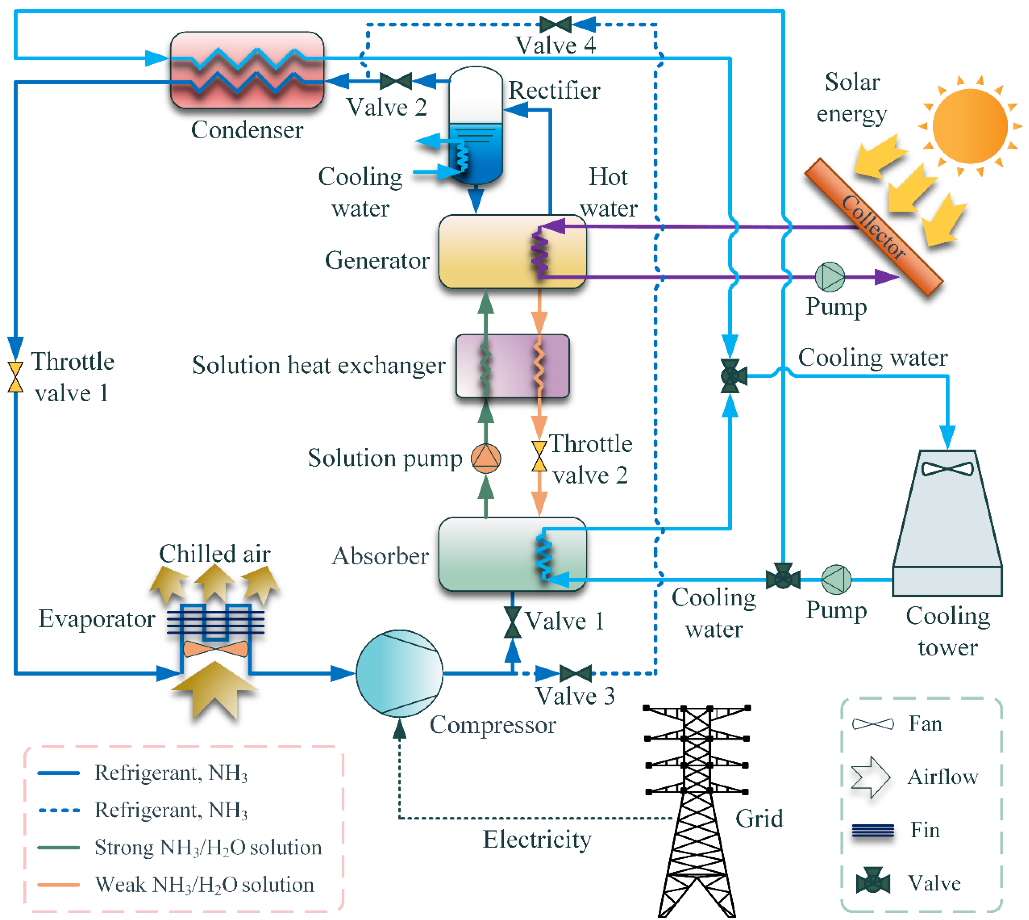
The schematic diagram of a solar-assisted two-stage cycle with thermal and mechanical compression processes is exhibited in
Figure 1. The cycle is composed of solar collector, cooling tower, compressor, thermal compressor (generator, absorber, solution heat exchanger, solution pump, and throttle valve 2), rectifier, condenser, throttle valve 1, evaporator, and bypass pipe (deep blue dotted line between condenser and compressor in
Figure 1). The thermal compressor is driven by the hot pressurized water heated by solar energy. Note that valves 1 and 2 are switched off and valves 3 and 4 are switched on when the solar energy is exhausted. It is demonstrated that the energy-saving feature of two-stage cycle with thermal and mechanical compression processes is straightforward, i.e., partial compressor power has been cut down by the heat-driven thermal compressor. Moreover, the energy saving amount of the layout is dependent on the evaporator, condenser, and inter-stage pressure (i.e., outlet pressure of compressor). Note that NH
3/H
2O is chosen as the working fluid for two-stage cycle with thermal and mechanical compression processes, which is attributed to its environmental friendliness and convenience.
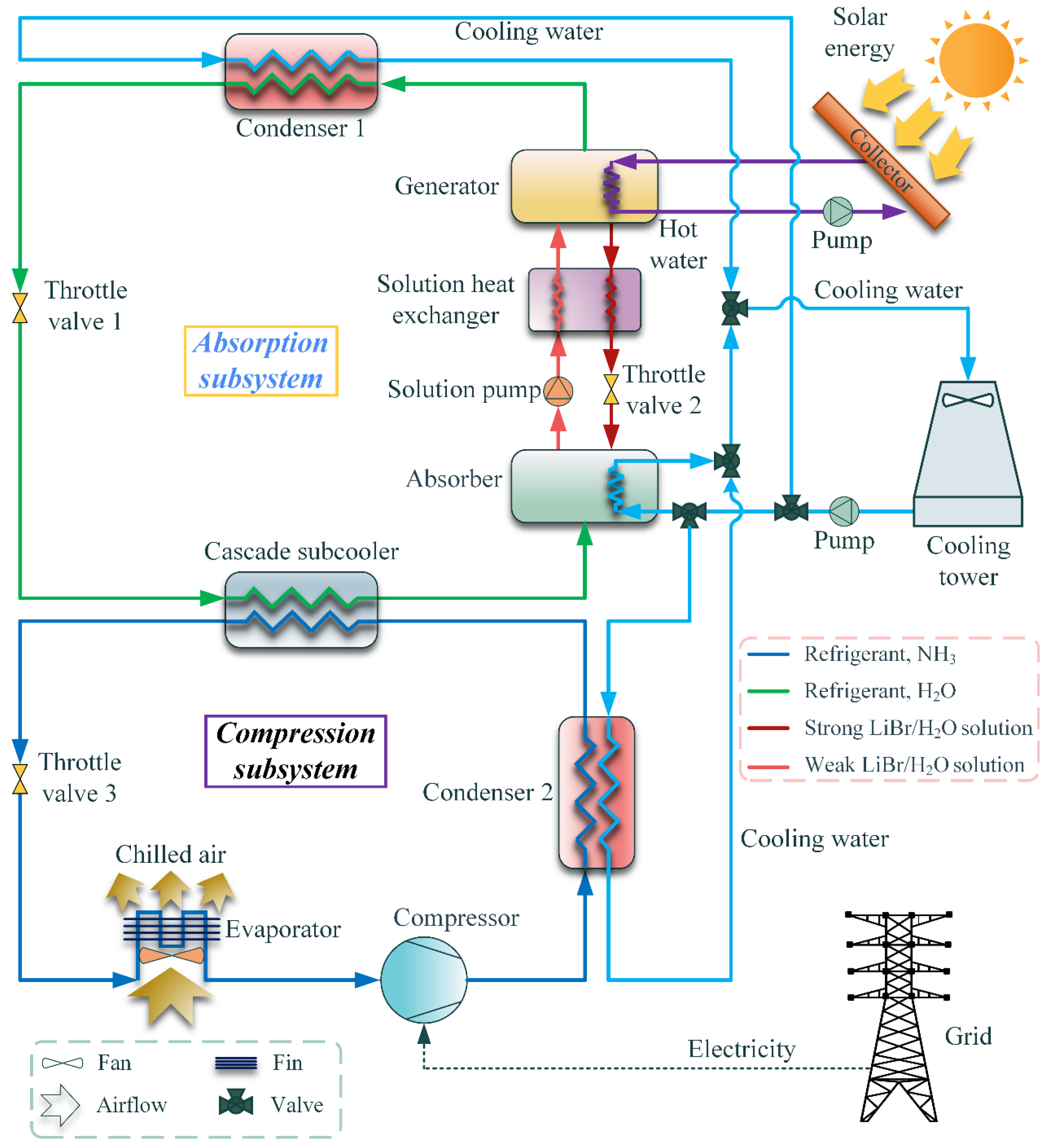
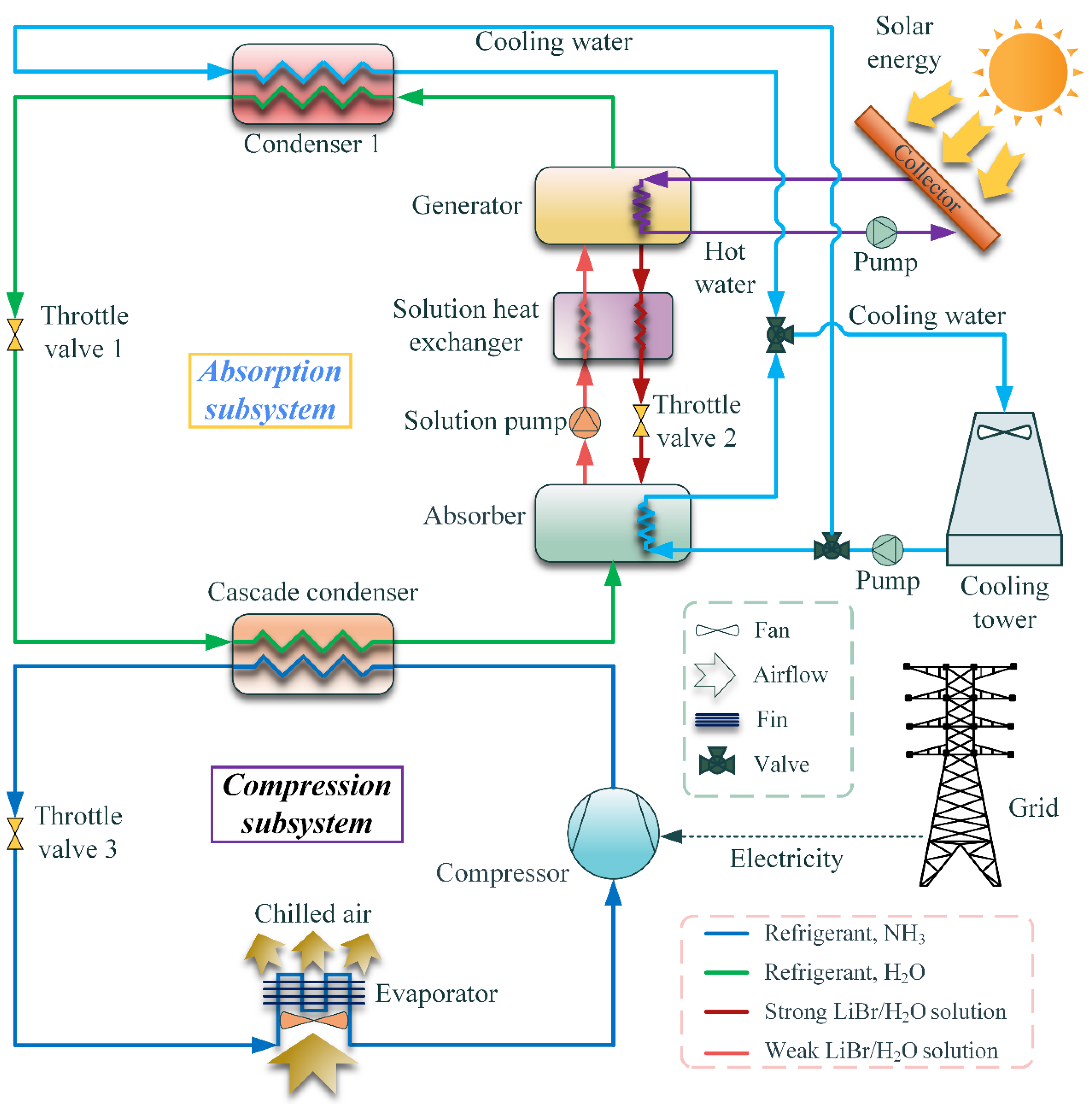
The schematic diagram of a solar-assisted hybrid cooling system with the cascade condensation process can be seen in
Figure 2. The corresponding system is made up of two subsystems that can be individually operated, i.e., absorption and compression subsystems, which are driven by solar heat and electricity, respectively. The energy saving characteristics of the layout with a cascade condensation process is that the condenser temperature is decreased, owing to the use of cooling output of absorption subsystems to cool down the condenser of compression one. Accordingly, the energy saving amount of the system is restricted by the evaporator temperature of both compression and absorption subsystems. Specially, the selection of working fluid pairs for the layout with a condensation process is flexible, because of the independence of the compression and absorption subsystem. In this study, the working fluid of the absorption and compression subsystem is selected as LiBr/H
2O and NH
3, respectively. The reason regarding the utilization of LiBr/H
2O absorption chillers lies in its lower temperature of driven heat source and higher
COP [
25].
The schematic diagram of the solar-assisted hybrid cooling system with a cascade subcooling process is displayed in
Figure 3. The layout with a cascade subcooling process is also composed of absorption and compression subsystems. The energy-saving mechanism of the system is that the specific cooling capacity has been enhanced by the subcooling process. Furthermore, the working substance is also chosen as LiBr/H
2O and NH
3, respectively, for absorption and compression subsystems.
Note that the solar-assisted hybrid cooling systems will be degraded into traditional vapor compression cycles when the thermal compressor or absorption chillers are switched off, because of the exhaustion of the solar heat source.
3. Model
3.1. Assumptions
The thermodynamic models of solar-assisted hybrid cooling systems are based on the following assumptions:
Systems run under stead conditions [
25].
Pressure and heat losses are neglected [
25].
The flows through the throttling devices are isenthalpic, and the solution pump power is neglected [
25].
Outlets of evaporators and condensers as well as solution outlets of generators and absorbers are saturated [
39].
The ammonia mass concentration of the refrigerant in the two-stage cycle with thermal and mechanical compression processes is 0.998 [
40].
Dead state temperature and pressure is 25 °C and 100 kPa, respectively. Enthalpy and entropy at the dead state are determined by the pure water properties [
41].
The temperature difference between the outlet and inlet of external fluid is fixed at 5 °C. The evaporator temperature of the absorption subsystem (
Te,as) in the layout with a cascade condensation process and cascade subcooling process and the outlet pressure of compressor in the two-stage cycle with thermal and mechanical compression processes is defined as intermediate temperature (
Tm) and inter-stage pressure, respectively. The evaporator temperature of solar-assisted cooling systems (
Te) is set as
; the condenser temperature (
Tc) and absorber temperature (
Ta) are set as
[
42]. The outlet temperature of the cascade heat exchangers in the compression side are set as
[
43]. Additionally, the generator temperature (
Tg) is equal to
[
44].
3.2. Thermodynamic Model
The thermodynamic model of solar-assisted cooling systems is analyzed based on the mass, energy and species conservation:
The energy-saving amount of the solar-assisted cooling systems is evaluated by the energy-saving factor (
ƞ), which is defined as the reduction of compressor power to compressor work of a single-stage vapor compression system (reference system).
The exergy efficiency (
ECOP) of hybrid systems is the total output exergy to the total input exergy.
The heat-powered coefficient of performance (
ψ) introduced in Ref. [
14] is utilized to assess the reduction of compressor work per unit of heat source for systems driven by heat and mechanical power, which is redefined based on the exergy viewpoint.
ψ denotes the efficiency of energy saving with low-grade heat for solar-assisted hybrid cooling systems.
Note that the duration in heat-driven processes (
γ) should be considered when calculating the compressor work as well as heat exergy for solar-assisted hybrid cooling systems with insufficient heat quantity, i.e., heat quantity is less than the heat load of generators.
The duration in heat-driven processes is defined according to [
45], which ranges from 0 to 1. Heat-driven processes can operate in the whole working period when the duration in heat-driven processes equals 1, i.e., the heat quantity satisfies the generator heat load.
The expression of compressor work and heat exergy for solar-assisted hybrid cooling systems with sufficient and insufficient heat quantity is listed in
Table 4. Note that the term
represents the specific reduction of compressor power associated with the heat-driven process.
4. Model Comparison and Case Study
The thermodynamic models of the layout with a cascade condensation process and layout with a cascade subcooling process have been validated in our previous study [
45], respectively, according to Refs. [
25,
39]. Good agreements were obtained. Moreover, the comparative parameters of two-stage cycle with thermal and mechanical compression processes are calculated according to the thermodynamic properties listed in Ref. [
3]. As displayed in
Table 5, the maximum relative error is less than 5%.
A case study with respect to the parametric analysis of a proposed thermodynamic model was carried out. The corresponding design condition of related systems is shown in
Table 6. Two cases, i.e., the heat quantity is equal to the heat load of generators (case 1, also known as the case of sufficient heat input) and is insufficient for the entire working period (case 2), are considered. That is, case 2 is related to the thermodynamic model with consideration of the duration in heat-driven processes. Note that the layout with a cascade subcooling process is suitable for the small-scale heat source; therefore, the heat quantity is much smaller than that of the two-stage cycle with thermal and mechanical compression processes and the layout with a cascade condensation process. The thermodynamic model is solved by the MATLAB program. The thermodynamic property of the LiBr/H
2O solution is calculated according to Patek and Klomfar [
46]. Additionally, the thermodynamic properties of NH
3 and H
2O are obtained by means of REFPROP 9.1 software.
5. Results and Discussion
There are four parts in this section: (1) system under sufficient heat input, (2) system under insufficient heat input, (3) optimum parameters for different working conditions, and (4) deficiency and outlook.
5.1. System under Sufficient Heat Input
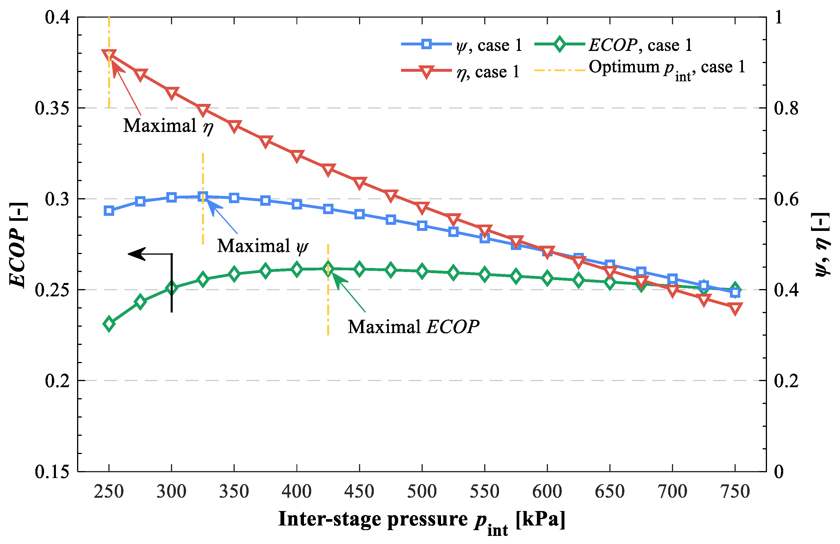
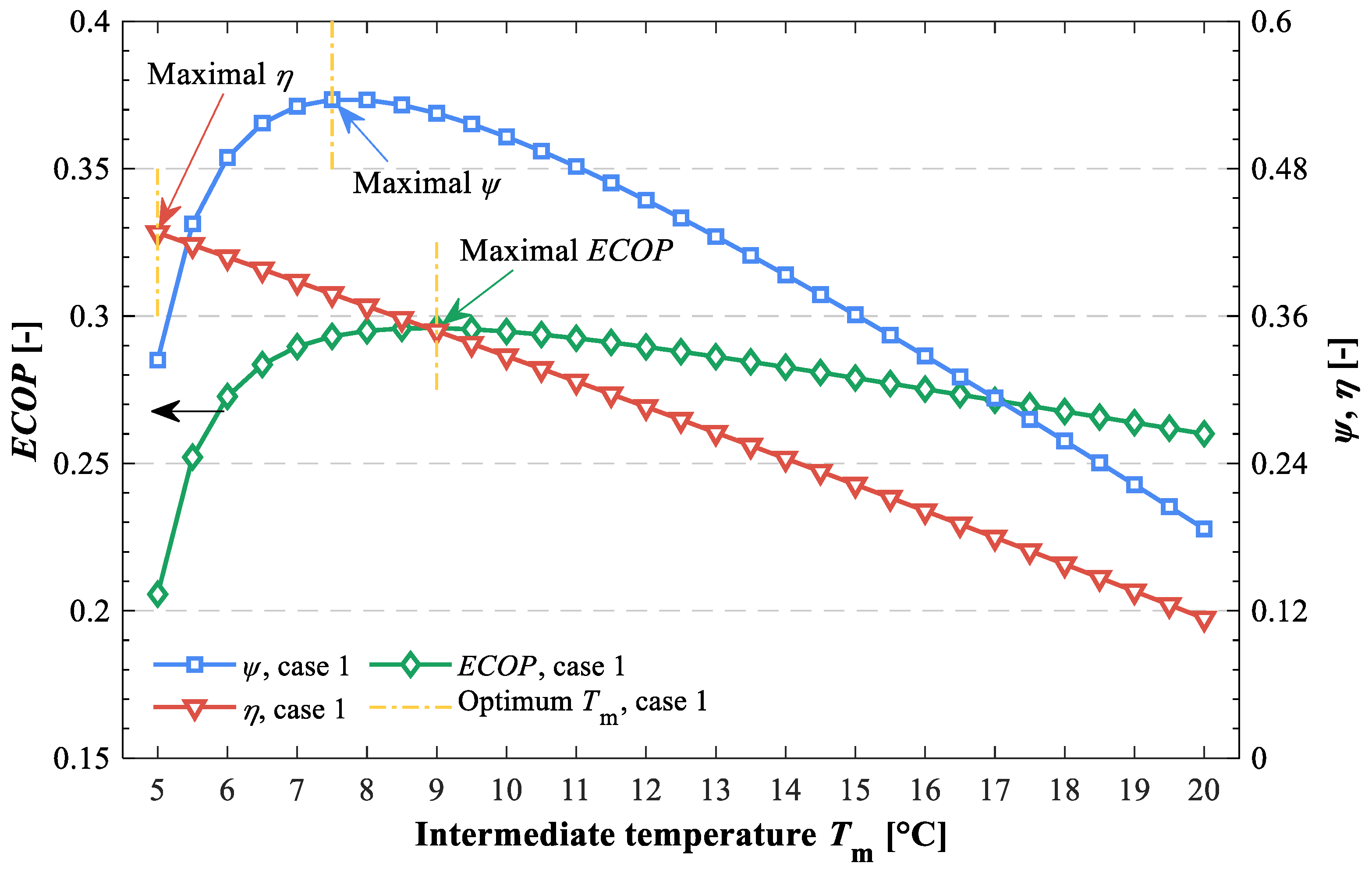
The effects of critical parameters on the performance indicators of solar-assisted hybrid cooling systems for case 1 are shown in
Figure 4,
Figure 5 and
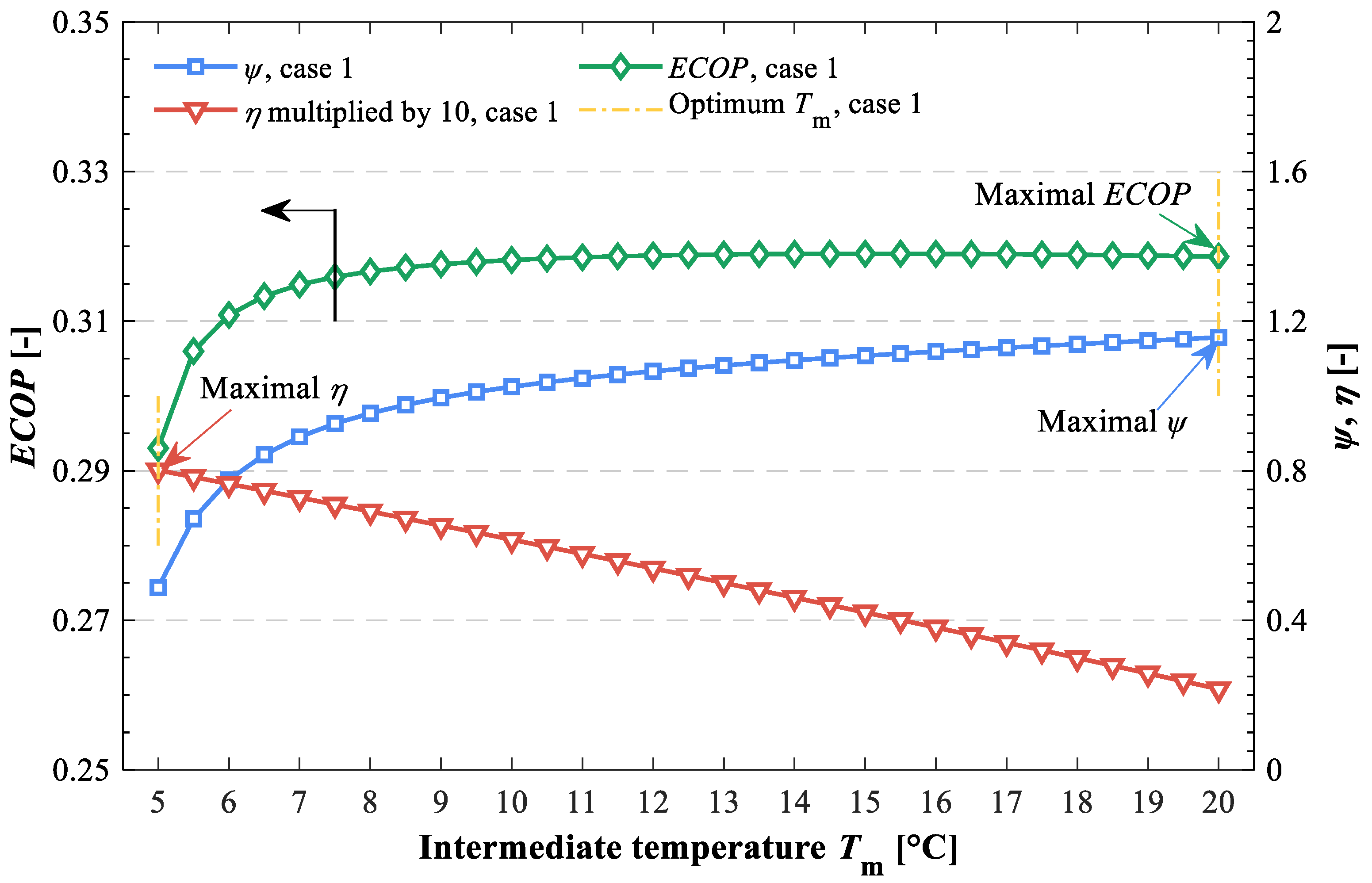
Figure 6. Note that the duration in heat-driven processes is equal to 1 in this case. It is observed that the different optimum parameters are obtained for various performance indicators. For maximum energy-saving factor, it represents that the compressor work consumption of hybrid cooling systems is lowest. Accordingly, lowering the inter-stage pressure and intermediate temperature is beneficial for the compressor work saving. As for the maximum exergy efficiency and heat powered coefficient of performance, both are associated with the compressor work and heat exergy consumption, i.e., the summation of compressor work and heat exergy is at a minimum for the former, and the compressor work saving to heat exergy is highest for the latter.
Optimum inter-stage pressures and intermediate temperatures associated with performance indicators for solar-assisted hybrid cooling systems have been listed and compared in
Table 7. It is found that the optimal critical parameters corresponding to different performance indicators are significantly different, e.g., the optimum inter-stage pressure ratio of energy saving factor, heat powered coefficient of performance, and exergy efficiency is 1:1.3:1.7. Note that the working guideline of solar-assisted hybrid cooling systems is chosen according to energy saving factor in the case of sufficient heat supply, because the heat-driven processes can operate in the entire working period regardless of inter-stage parameters to maximize the energy saving amount.
5.2. System under Insufficient Heat Input
In this section, the effects of critical parameters on solar-assisted hybrid cooling system performance under insufficient heat input (case 2) are analyzed. Note that the duration in heat-driven processes is less than 1 in this case, and the systems will be degraded into traditional vapor compression cycles when the heat-driven processes are switched off.
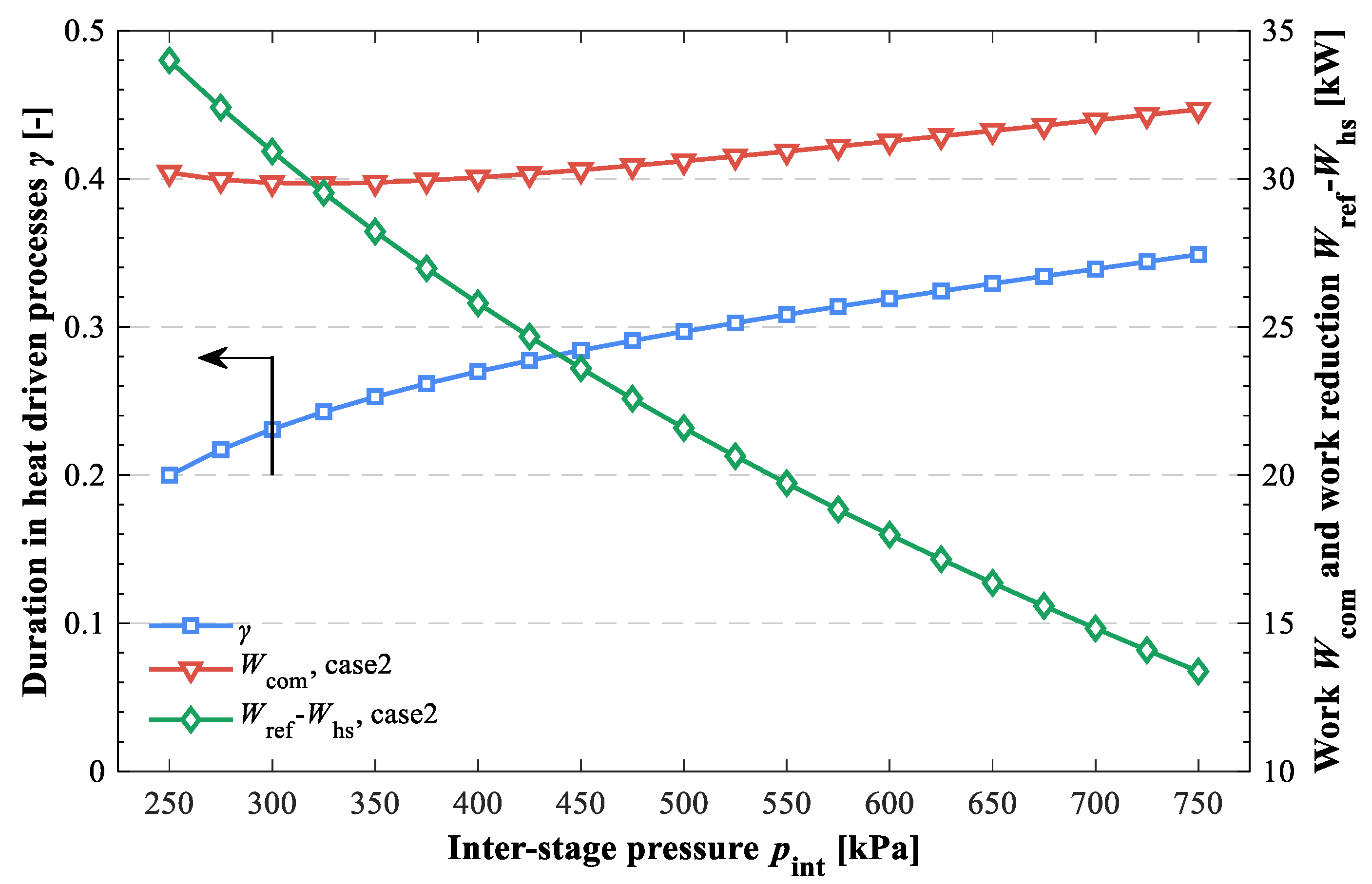
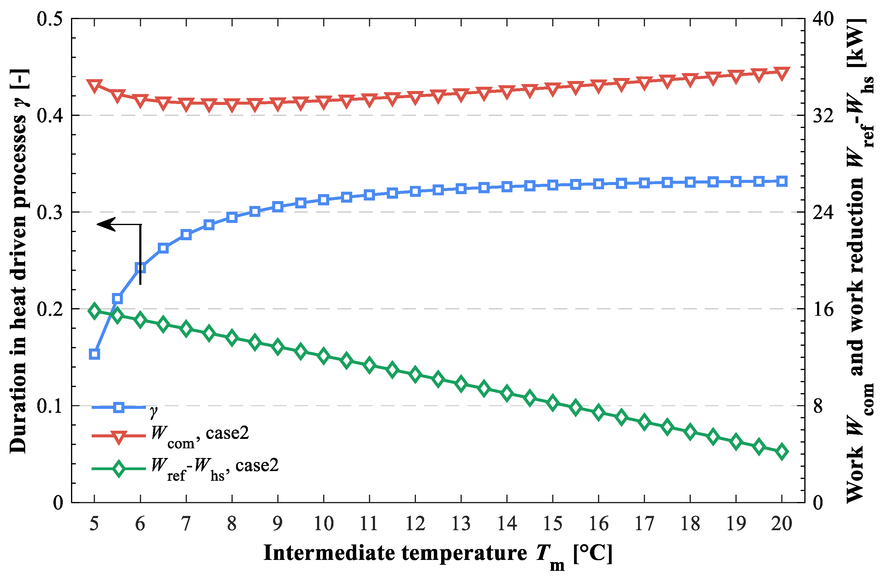
The effects of critical parameters on duration in heat-driven processes and compressor work in case 2 are exhibited in
Figure 7,
Figure 8 and
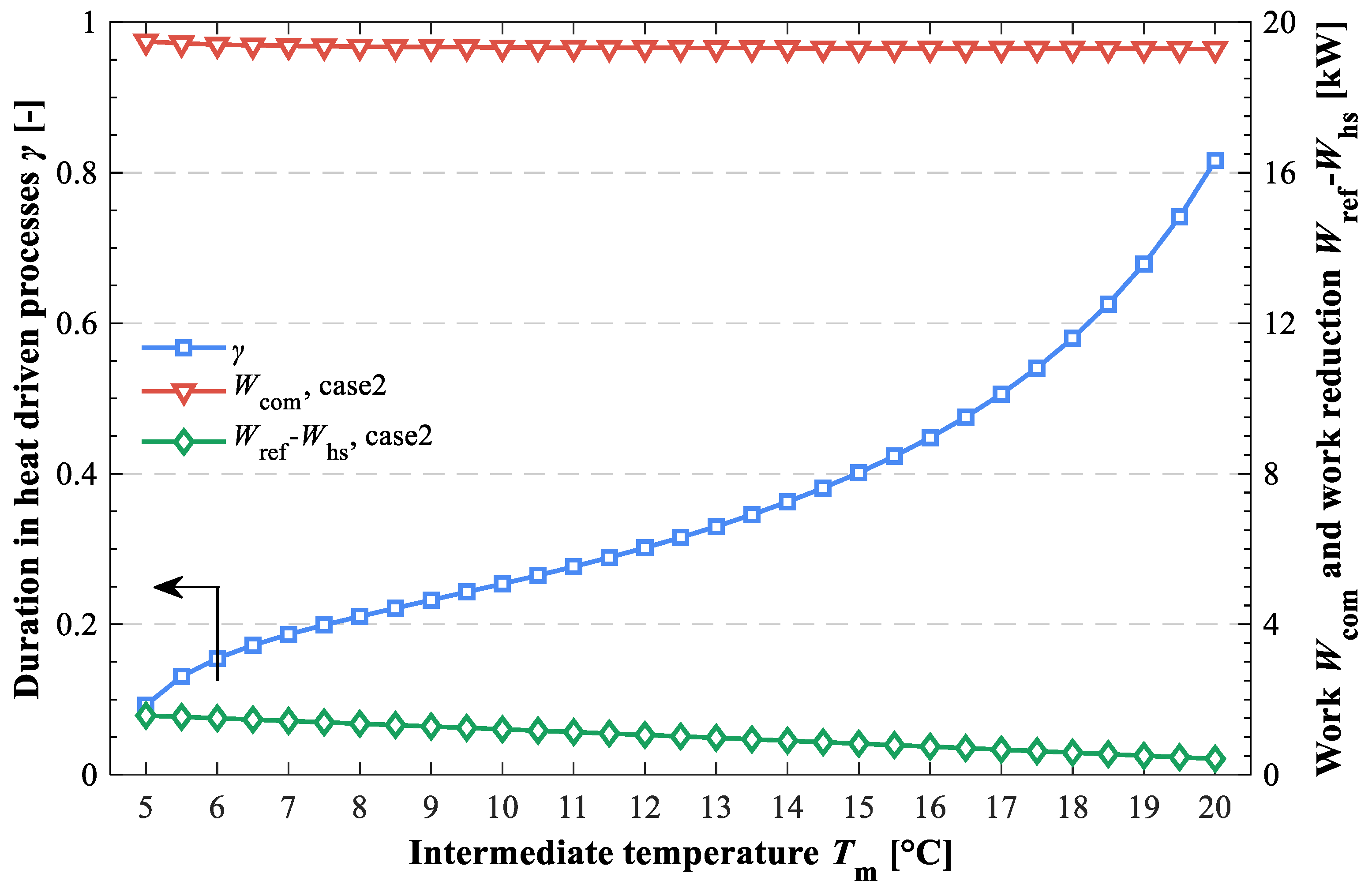
Figure 9. There is no doubt that the duration in heat-driven processes enhances with the enhancement of inter-stage pressure or intermediate temperature, owing to the reduction of heat load of generators. Note that the duration in heat-driven processes for the layout with a cascade condensation process (blue line in
Figure 8) tends to be stable with the increase in intermediate temperature, because the
COP of the absorption chiller reaches a plateau, and its cooling power almost keeps constant caused by the little variation of latent heat in the condensation process. Furthermore, it is observed that the specific drop in compressor work associated with the heat-driven process lowers simultaneously. Thereby, the trend of total compressor power is complicated. For the two-stage cycle with thermal and mechanical compression processes as well as the layout with a cascade condensation process, there is an optimum inter-stage pressure and intermediate temperature that minimizes the total compress work, i.e., around 325 kPa and 7.5 °C, which is 61.45% of and close to the geometric mean of the evaporator and condenser pressure and temperature, respectively. This is because the lower duration in heat-driven processes impacts the energy saving performance of the hybrid cooling systems with lower inter-stage pressure and intermediate temperature. For the layout with a cascade subcooling process, the compressor work varies slightly with the increase in intermediate temperature. In this regard, it is attributed to the effect of duration in heat-driven processes and to specific falls in compressor work that are nearly offset in arbitrary intermediate temperature.
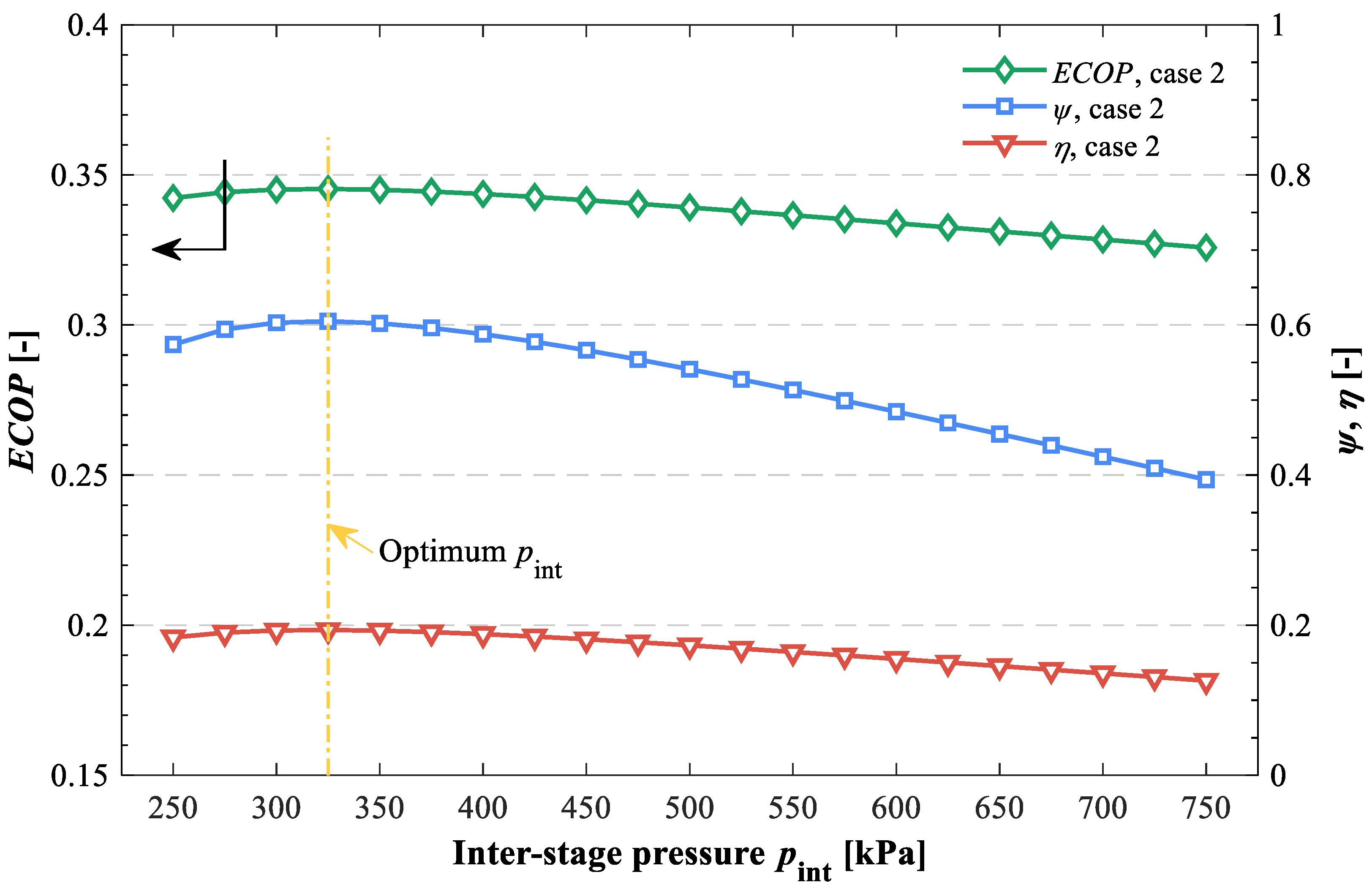
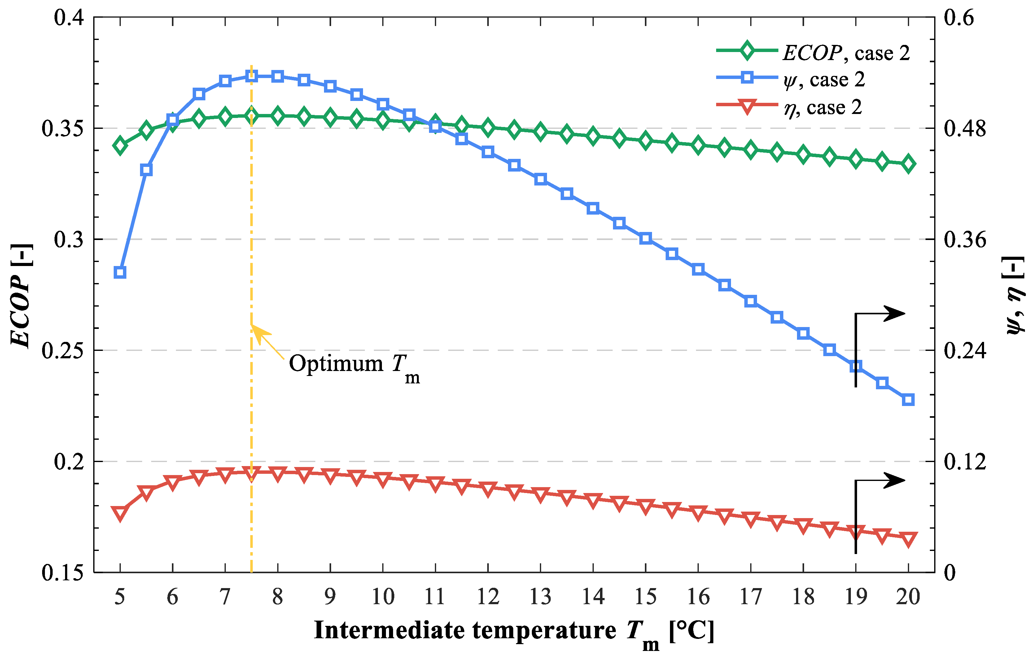
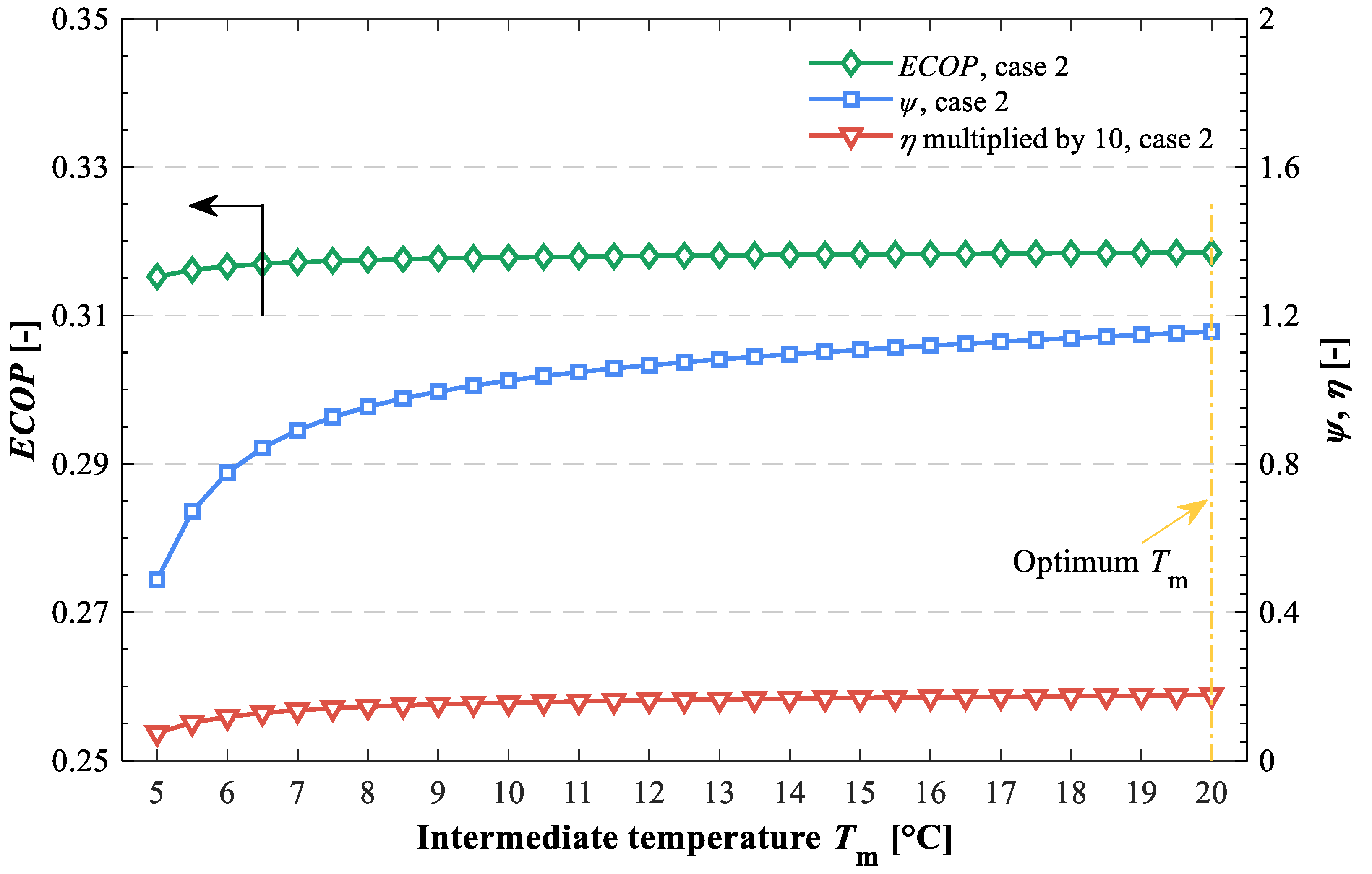
The effects of critical parameters on the performance indicators of solar-assisted hybrid cooling systems for case 2 are displayed in
Figure 10,
Figure 11 and
Figure 12. Note that the variation trend of heat-powered coefficient of performance is greater than that of exergy efficiency and energy-saving factor, which is attributed to the higher reduction of heat exergy consumption. It can be easily known that the performance indicators are related to the compressor work in case 2 according to Equations (4)–(6). Therefore, performance indicators exhibit the same variation trend, i.e., identical optimum inter-stage pressure as well as intermediate temperature is obtained, when the duration in heat-driven processes has been considered. That is, the optimum inter-stage pressure and intermediate temperature is 61.45% of and close to the geometric mean of the evaporator and condenser pressure and temperature, respectively, for two-stage cycle with thermal and mechanical compression processes and the layout with a cascade condensation process. For the layout with a cascade subcooling process, although the optimum critical parameter is similar to the other two systems, the performance indicators are insensitive to the intermediate temperature from the practical operation viewpoint, i.e., the total compressor work is almost independent of intermediate temperature.
5.3. Optimum Parameters for Different Working Conditions
In this section, optimum intermediate temperature as well as inter-stage pressure for different conditions has been discussed in detail. Note that the intermediate temperature has few effects on the performance of the layout with a cascade subcooling process; thus, the discussion of corresponding layout has been omitted in this section. Moreover, the optimum intermediate temperature and inter-stage pressure have been processed as dimensionless by the geometric mean of the evaporator and condenser temperature as well as by the geometric mean of the evaporator and condenser pressure (, ), respectively, to make the results generally applicable.
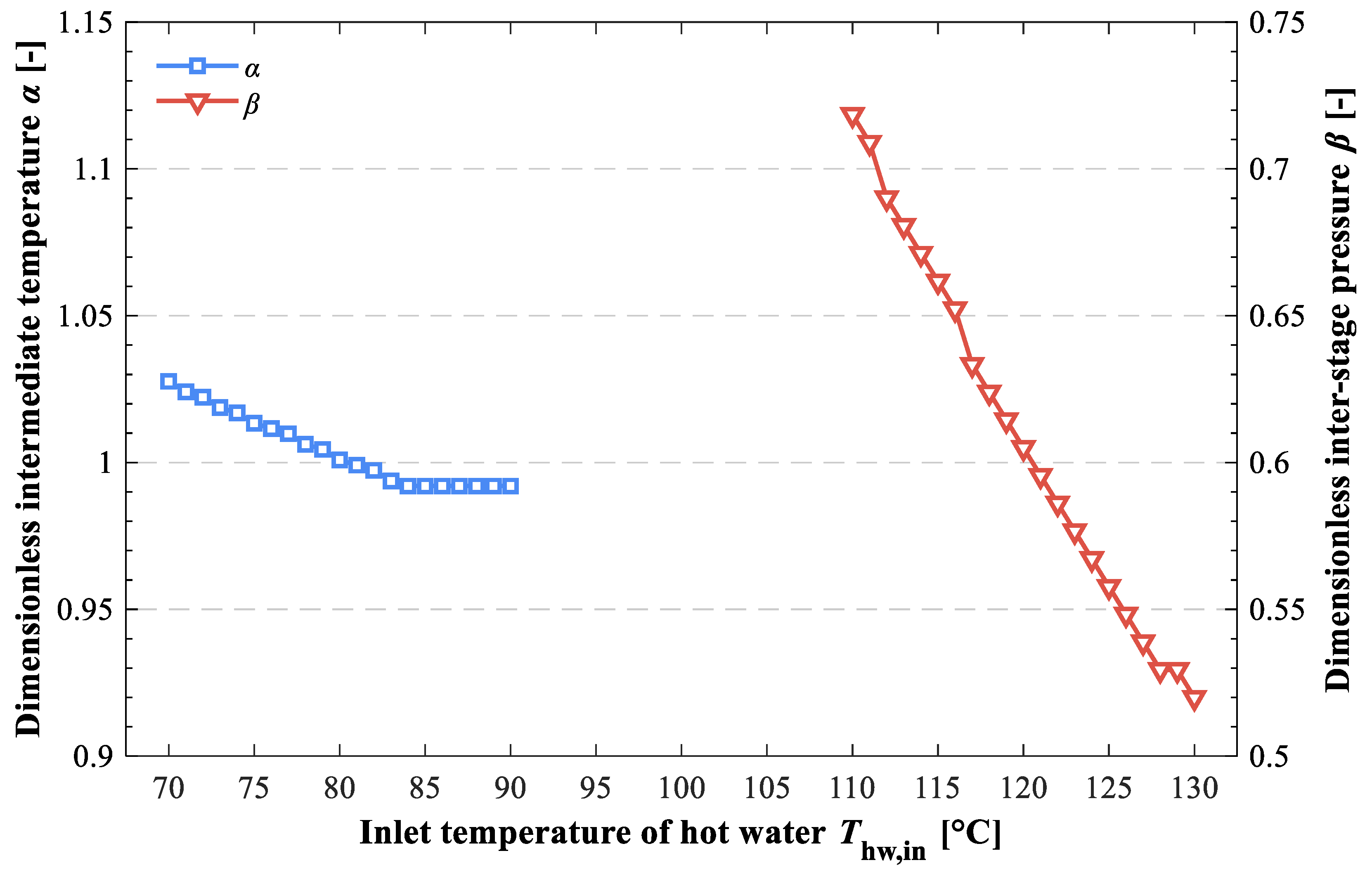
Figure 13 displays the effect of inlet temperature of hot water on dimensionless optimum intermediate temperature and inter-stage pressure, respectively, for the layout with a cascade condensation process and two-stage cycle with thermal and mechanical compression processes. Note that the optimum intermediate temperature for the layout with a condensation process is close to the geometric mean of the evaporator and condenser temperature (
α is almost identical to 1), while the optimum inter-stage pressure is less than the geometric mean of the evaporator and condenser pressure (maximum
β is around 0.72). It is found that the optimal critical parameters generally decrease with the enhancement of inlet temperature of hot water, which is attributed to the reduction of the lower limit of evaporator temperature of the absorption chiller and absorber pressure of the thermal compressor, respectively, for the layout with a cascade condensation process and two-stage cycle with thermal and mechanical compression processes. The dimensionless optimum intermediate temperature is insensitive to the generator temperature for the layout with a cascade condensation process, i.e., it lowers by 3.47% when the inlet temperature of hot water rises from 70 to 90 °C. Note that the optimum intermediate temperature for the layout with a condensation process keeps constant when the inlet temperature reaches to around 84 °C, because the lower limit of the evaporator temperature of the LiBr/H
2O absorption chiller cannot be less than 5 °C, owing to the limitation of water solidification temperature. The dimensionless optimum inter-stage pressure for the two-stage cycle with thermal and mechanical compression processes is sensitive to the inlet temperature of hot water, i.e., it decreases by 26.67%, with a 20 °C rise in generator temperature.
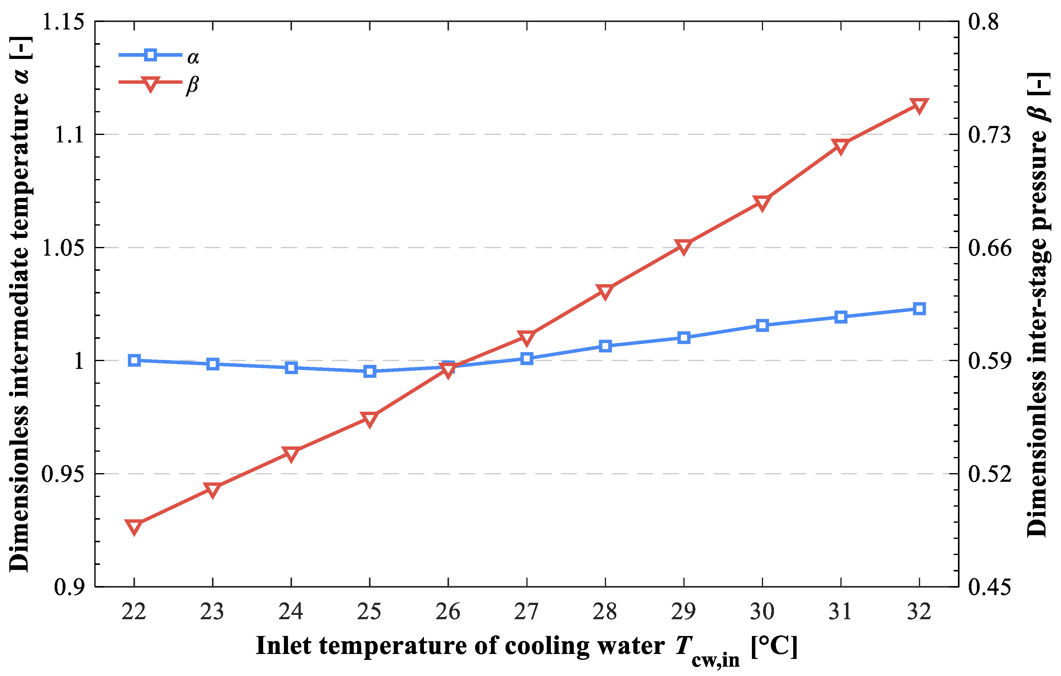
The effect of inlet temperature of cooling water on dimensionless optimum intermediate temperature and inter-stage pressure can be seen in
Figure 14. It is noteworthy that the lower limit of the evaporator temperature of the absorption subsystem for the layout with a cascade condensation process and absorber pressure of the thermal compressor for the two-stage cycle with thermal and mechanical compression processes will be enhanced with the growth of inlet temperature of the cooling water. Consequently, the optimum inter-stage pressure for the two-stage cycle with thermal and mechanical compression processes increases with the rise in inlet temperature of the cooling water, i.e., it increases by 47.27% with a 10 °C rise in condenser temperature. For the layout with a cascade condensation process, the dimensionless optimum intermediate temperature decreases to a minimum value first, and then increases because the optimum intermediate temperature remains at 5 °C (lower limit of evaporator temperature of LiBr/H
2O absorption chiller), while the geometric mean of the evaporator and condenser temperature increases in the case of a relatively low condenser temperature. The maximum difference of dimensionless optimum intermediate temperature is around 2.79% with the variation in condenser temperature.
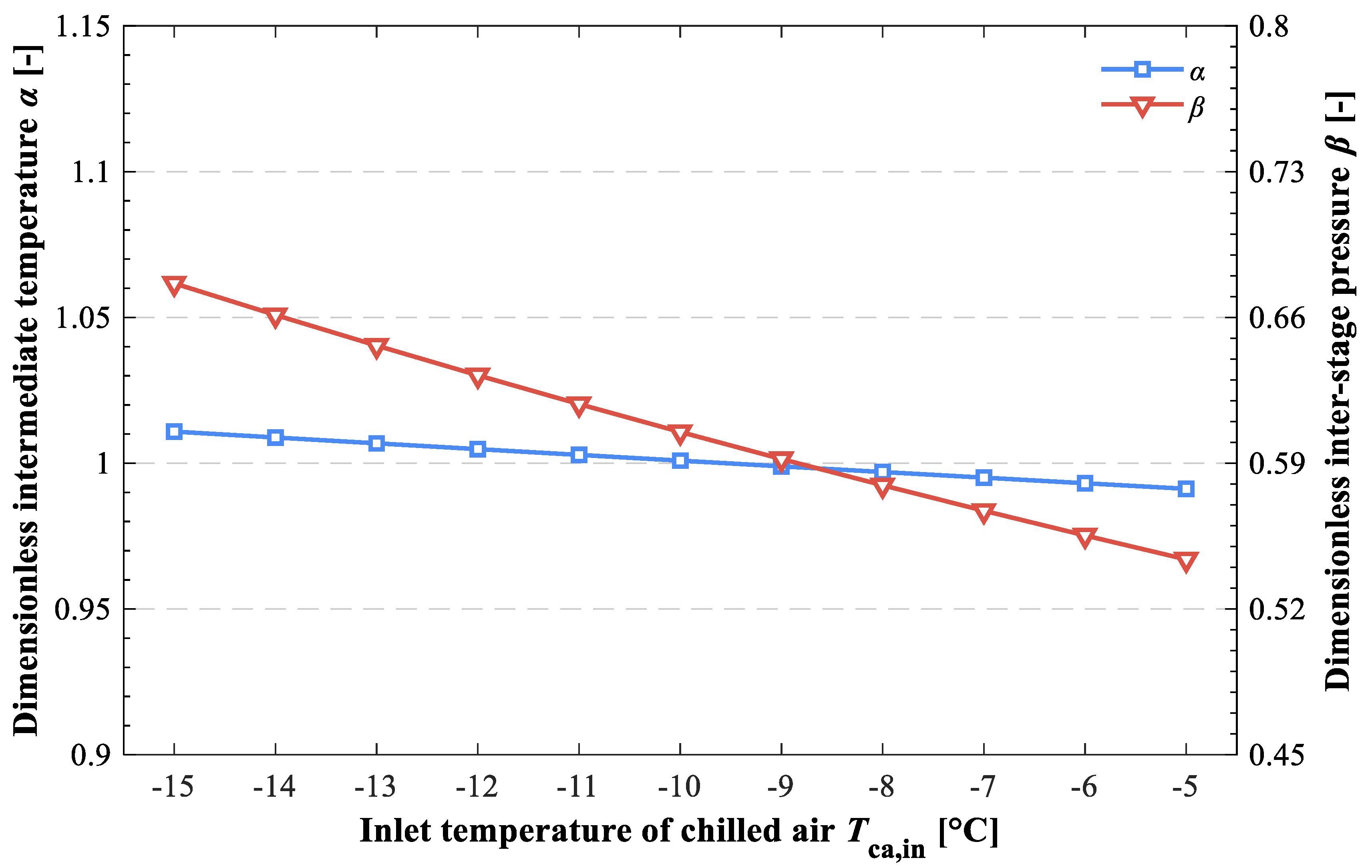
The effect of inlet temperature of chilled air on dimensionless optimum intermediate temperature and inter-stage pressure is exhibited in
Figure 15. It is obvious that the variation in inlet temperature of chilled air has no effect on the performance of the absorption chiller and thermal compressor, respectively, for the layout with a cascade condensation process and two-stage cycle with thermal and mechanical compression processes. Furthermore, the change in evaporator temperature almost slightly influences the refrigerant flow rate. Namely, the optimum intermediate temperature and inter-stage pressure are constant for the corresponding layouts. Note that the decrease in dimensionless optimum intermediate temperature and inter-stage pressure is attributed to the enhancement of geometric mean of the evaporator and condenser temperature and pressure, respectively. The dimensionless optimum intermediate temperature and inter-stage pressure comes down by 1.94% and 24.38%, respectively, when the inlet temperature of chilled air grows from −15 to −5 °C.
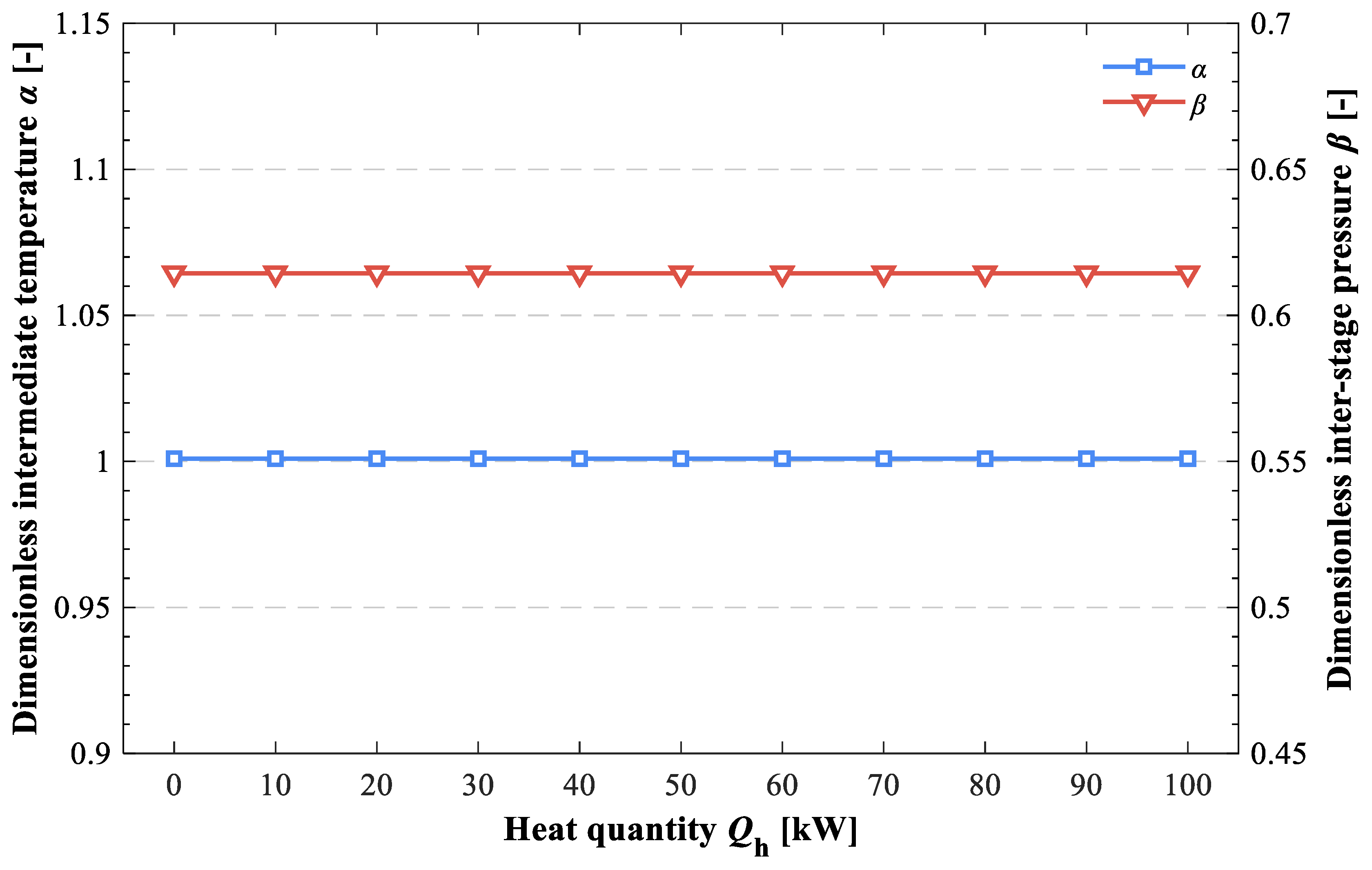
The effect of heat quantity on dimensionless optimum intermediate temperature and inter-stage pressure is shown in
Figure 16. It is demonstrated that the optimum intermediate temperature for the layout with a cascade condensation process as well as the optimum inter-stage pressure for the two-stage cycle with thermal and mechanical compression processes are independent of the heat quantity. This phenomenon can be exactly illustrated by the results regarding the heat-powered coefficient of performance in
Section 5.1 (the heat-powered coefficient of performance in cases 1 and 2 coincide). That is, the dimensionless optimum intermediate temperature and inter-stage pressure are dependent on the generator, condenser, absorber, and evaporator temperature.
5.4. Deficiency and Outlook
Although the model of duration in the heat-driven processes is accurate in steady conditions, it has some challenges in engineering applications, which are generally unsteady states. Accordingly, a further experimental study can be implemented to fit the expression of duration in heat-driven processes as closely as possible.
The temperature level of the driven heat source and solar collector for solar-assisted hybrid cooling systems is different when various working substances are considered, which has different energy quality and capital cost, respectively. For example, a solar flat collector as well as a low-temperature heat source are suitable for H2O/LiBr absorption chillers. The corresponding discussion has been omitted in this paper. Further investigations are needed to improve the comparative analysis of solar-assisted hybrid cooling systems in energy, exergy, and economic aspects.
6. Conclusions
In this study, a thermodynamic model of solar-assisted hybrid cooling systems with consideration of duration in heat-driven processes has been established to assess the system performance in entire working periods and is applied to three general absorption–compression-integrated cycles. The interaction of duration in heat-driven processes and parameters in system performance is discussed. Furthermore, optimal parameters for different working conditions are obtained. The main conclusions are summarized as follows:
(1) The phenomenon that optimal parameters associated with various performance indicators are conflicting is corrected by considering the duration of heat-driven processes in the total compressor power, i.e., optimal parameters corresponding to the maximal exergy efficiency, peak heat-powered coefficient of performance, and the minimal total compressor power are identical.
(2) The dimensionless optimum inter-stage pressure is sensitive to different working conditions for the two-stage cycle with thermal and mechanical compression processes. The dimensionless optimum inter-stage pressure decreases by 26.67% and 24.38%, respectively with a 20 and 10 °C enhancement in generator and evaporator temperature, while it increases by 47.27% when the inlet temperature of the cooling water increases from 22 to 32 °C.
(3) The dimensionless optimum critical parameter is insensitive to different working conditions for the layout with a cascade condensation process, i.e., it is close to the geometric mean of the evaporator and condenser temperature. The variation rate of the dimensionless optimum intermediate temperature is less than 4% for different working conditions.
(4) The energy saving is almost independent of intermediate temperature for the layout with a cascade subcooling process, and performance indicators are increased slightly with the rise in intermediate temperature.
Author Contributions
Conceptualization, Z.L.; Investigation, Z.P.; Methodology, Z.P.; Resources, Z.L.; Software, Z.P. and J.Y.; Supervision, Z.L.; Validation, J.Z.; Writing—original draft, Z.P.; Writing—review and editing, Z.L. All authors have read and agreed to the published version of the manuscript.
Funding
This research was funded by [Natural Science Foundation of Guangdong Province] grant number [2020B1515120035 and 2021A1515010265], [Fundamental Research Funds for the Central Universities] grant number [2020ZYGXZR026], [Key Laboratory of Efficient and Clean Energy Utilization of Guangdong Higher Education Institutes] grant number [KLB10004], and [Zhuhai Industry-University-Research Cooperation Project] grant number [ZH22017001210017PWC].
Institutional Review Board Statement
Not applicable.
Informed Consent Statement
Not applicable.
Data Availability Statement
Data is contained within the article.
Conflicts of Interest
The authors declare no conflict of interest.
Nomenclature
| Abbreviations | |
| Exp | experimental |
| GWP | global warming potential |
| LCC | layout with a cascade condensation process |
| LCS | layout with a cascade subcooling process |
| Th | theoretical |
| TSCTMC | two-stage cycle with thermal and mechanical compression processes |
| Symbols | |
| COP | coefficient of performance |
| ECOP | exergy efficiency |
| ex | specific exergy (kJ/kg) |
| Ex | exergy rate (kW) |
| h | specific enthalpy (kJ/kg) |
| m | mass flow rate (kg/s) |
| Q | energy (kW) |
| Qh | heat quantity (kW) |
| T | temperature (K) |
| W | work (kW) |
| X | concentration |
| Greek | |
| Δ | difference |
| α | dimensionless optimum intermediate temperature |
| β | dimensionless optimum inter-stage pressure |
| γ | duration in heat-driven processes |
| ψ | heat powered coefficient of performance |
| η | efficiency, effectiveness, energy saving factor |
| Subscripts | |
| a | absorber |
| as | absorption subsystem |
| c | condenser |
| ca | chilled air |
| com | compressor |
| cw | cooling water |
| e | evaporator |
| g | generator |
| hs | hybrid cooling system |
| hw | hot water |
| in | inlet |
| int | inter-stage |
| is | isentropic |
| m | intermediate |
| opt | optimum |
| out | outlet |
| pump | pump |
| ref | reference |
| shx | solution heat exchanger |
| tot | total |
References
- Soltani, M.; Dehghani-Sanij, A.; Sayadnia, A.; Kashkooli, F.M.; Gharali, K.; Mahbaz, S.; Dusseault, M.B. Investigation of Airflow Patterns in a New Design of Wind Tower with a Wetted Surface. Energies 2018, 11, 1100. [Google Scholar] [CrossRef] [Green Version]
- De, R.K.; Ganguly, A. Modeling and analysis of a solar thermal-photovoltaic-hydrogen-based hybrid power system for running a standalone cold storage. J. Clean. Prod. 2021, 293, 126202. [Google Scholar] [CrossRef]
- Zhang, N.; Lior, N.; Han, W. Performance Study and Energy Saving Process Analysis of Hybrid Absorption-Compression Refrigeration Cycles. J. Energy Resour. Technol. 2016, 138, 061603. [Google Scholar] [CrossRef]
- Meng, X.; Zheng, D.; Wang, J.; Li, X. Energy saving mechanism analysis of the absorption–compression hybrid refrigeration cycle. Renew. Energy 2013, 57, 43–50. [Google Scholar] [CrossRef]
- Wu, W.; Shi, W.; Wang, B.; Li, X. Annual performance investigation and economic analysis of heating systems with a compression-assisted air source absorption heat pump. Energy Convers. Manag. 2015, 98, 290–302. [Google Scholar] [CrossRef]
- Wu, W.; Zhang, H.; You, T.; Li, X. Thermodynamic Investigation and Comparison of Absorption Cycles Using Hydrofluoroolefins and Ionic Liquid. Ind. Eng. Chem. Res. 2017, 56, 9906–9916. [Google Scholar] [CrossRef]
- Wu, W.; Shi, W.; Wang, J.; Wang, B.; Li, X. Experimental investigation on NH3–H2O compression-assisted absorption heat pump (CAHP) for low temperature heating under lower driving sources. Appl. Energy 2016, 176, 258–271. [Google Scholar] [CrossRef]
- Wang, J.; Wang, B.; Li, X.; Wu, W.; Shi, W. Performance analysis on compression-assisted absorption heat transformer: A new low-temperature heating system with higher heating capacity under lower ambient temperature. Appl. Therm. Eng. 2018, 134, 419–427. [Google Scholar] [CrossRef]
- Wu, W.; Wang, B.; Shang, S.; Shi, W.; Li, X. Experimental investigation on NH3–H2O compression-assisted absorption heat pump (CAHP) for low temperature heating in colder conditions. Int. J. Refrig. 2016, 67, 109–124. [Google Scholar] [CrossRef]
- Wu, W.; Wang, B.; You, T.; Wang, J.; Shi, W.; Li, X. Compression-assisted absorption cycles using ammonia and various ionic liquids for cleaner heating. J. Clean. Prod. 2018, 195, 890–907. [Google Scholar] [CrossRef]
- Wu, W.; Leung, M.; Ding, Z.; Huang, H.; Bai, Y.; Deng, L. Comparative analysis of conventional and low-GWP refrigerants with ionic liquid used for compression-assisted absorption cooling cycles. Appl. Therm. Eng. 2020, 172, 115145. [Google Scholar] [CrossRef]
- Liu, X.; Ye, Z.; Bai, L.; He, M. Performance comparison of two absorption-compression hybrid refrigeration systems using R1234yf/ionic liquid as working pair. Energy Convers. Manag. 2019, 181, 319–330. [Google Scholar] [CrossRef]
- Wu, W.; You, T.; Zhang, H.; Li, X. Comparisons of different ionic liquids combined with trans-1,3,3,3-tetrafluoropropene (R1234ze(E)) as absorption working fluids. Int. J. Refrig. 2018, 88, 45–57. [Google Scholar] [CrossRef]
- Zheng, D.; Meng, X. Ultimate refrigerating conditions, behavior turning and a thermodynamic analysis for absorption–compression hybrid refrigeration cycle. Energy Convers. Manag. 2012, 56, 166–174. [Google Scholar] [CrossRef]
- Sun, Y.; Di, G.; Wang, J.; Wang, X.; Wu, W. Performance analysis of R1234yf/ionic liquid working fluids for single-effect and compression-assisted absorption refrigeration systems. Int. J. Refrig. 2020, 109, 25–36. [Google Scholar] [CrossRef]
- Jain, V.; Kachhwaha, S.S.; Sachdeva, G. Thermodynamic performance analysis of a vapor compression–absorption cascaded refrigeration system. Energy Convers. Manag. 2013, 75, 685–700. [Google Scholar] [CrossRef]
- Kairouani, L.; Nehdi, E. Cooling performance and energy saving of a compression–absorption refrigeration system assisted by geothermal energy. Appl. Therm. Eng. 2006, 26, 288–294. [Google Scholar] [CrossRef]
- He, H.; Wang, L.; Yuan, J.; Wang, Z.; Fu, W.; Liang, K. Performance evaluation of solar absorption-compression cascade refrigeration system with an integrated air-cooled compression cycle. Energy Convers. Manag. 2019, 201, 112153. [Google Scholar] [CrossRef]
- Cimsit, C. Thermodynamic performance analysis of the double effect absorption-vapour compression cascade refrigeration cycle. J. Therm. Sci. Technol. 2018, 13, JTST0007. [Google Scholar] [CrossRef] [Green Version]
- Sun, X.; Liu, L.; Dong, Y.; Zhuang, Y.; Zhang, L.; Du, J. Superstructure-Based Simultaneous Optimization of a Heat Exchanger Network and a Compression–Absorption Cascade Refrigeration System for Heat Recovery. Ind. Eng. Chem. Res. 2020, 59, 16017–16028. [Google Scholar] [CrossRef]
- Chinnappa, J.; Crees, M.; Murthy, S.S.; Srinivasan, K. Solar-assisted vapor compression/absorption cascaded air-conditioning systems. Sol. Energy 1993, 50, 453–458. [Google Scholar] [CrossRef]
- Fernández-Seara, J.; Sieres, J.; Vázquez, M. Compression–absorption cascade refrigeration system. Appl. Therm. Eng. 2006, 26, 502–512. [Google Scholar] [CrossRef]
- Garimella, S.; Brown, A.M.; Nagavarapu, A.K. Waste heat driven absorption/vapor-compression cascade refrigeration system for megawatt scale, high-flux, low-temperature cooling. Int. J. Refrig. 2011, 34, 1776–1785. [Google Scholar] [CrossRef]
- Nagavarapu, A.K.; Garimella, S. High-flux thermal management at megawatt scale using a double-effect absorption/vapor-compression cascade refrigeration cycle. Int. J. Refrig. 2020, 119, 257–267. [Google Scholar] [CrossRef]
- Cimsit, C.; Ozturk, I.T. Analysis of compression–absorption cascade refrigeration cycles. Appl. Therm. Eng. 2012, 40, 311–317. [Google Scholar] [CrossRef]
- Agarwal, S.; Arora, A.; Arora, B. Energy and exergy analysis of vapor compression–triple effect absorption cascade refrigeration system. Eng. Sci. Technol. Int. J. 2020, 23, 625–641. [Google Scholar] [CrossRef]
- Jain, V.; Sachdeva, G.; Kachhwaha, S. Thermodynamic modelling and parametric study of a low temperature vapour compression-absorption system based on modified Gouy-Stodola equation. Energy 2015, 79, 407–418. [Google Scholar] [CrossRef]
- Jain, V.; Sachdeva, G.S.; Kachhwaha, S. Performance analysis of a vapour compression-absorption cascaded refrigeration system with undersized evaporator and condenser. J. Energy S. Afr. 2014, 25, 23–36. [Google Scholar] [CrossRef]
- Salhi, K.; Korichi, M.; Ramadan, K. Thermodynamic and thermo-economic analysis of compression–absorption cascade refrigeration system using low-GWP HFO refrigerant powered by geothermal energy. Int. J. Refrig. 2018, 94, 214–229. [Google Scholar] [CrossRef]
- Colorado, D.; Rivera, W. Performance comparison between a conventional vapor compression and compression-absorption single-stage and double-stage systems used for refrigeration. Appl. Therm. Eng. 2015, 87, 273–285. [Google Scholar] [CrossRef]
- Liu, L.; Li, Z.; Jing, Y.; Lv, S. Energetic, economic and environmental study of cooling capacity for absorption subsystem in solar absorption-subcooled compression hybrid cooling system based on data of entire working period. Energy Convers. Manag. 2018, 167, 165–175. [Google Scholar] [CrossRef]
- Salajeghe, M.; Ameri, M. Energy and exergy analysis of subcooling the condenser outlet refrigerant in a compression-absorption cascade refrigeration system. Int. J. Exergy 2015, 18, 234–250. [Google Scholar] [CrossRef]
- Jain, V.; Colorado, D. Thermoeconomic and feasibility analysis of novel transcritical vapor compression-absorption integrated refrigeration system. Energy Convers. Manag. 2020, 224, 113344. [Google Scholar] [CrossRef]
- Li, Z.; Chen, E.; Jing, Y.; Lv, S. Thermodynamic relationship of subcooling power and increase of cooling output in vapour compression chiller. Energy Convers. Manag. 2017, 149, 254–262. [Google Scholar] [CrossRef]
- Chen, E.; Li, Z.; Yu, J.; Xu, Y.; Yu, Y. Experimental research of increased cooling output by dedicated subcooling. Appl. Therm. Eng. 2019, 154, 9–17. [Google Scholar] [CrossRef]
- He, L.; Wang, S.; Liu, S.; Xuan, W. Numerical and experimental evaluation of the performance of a coupled vapour absorption-compression refrigeration configuration. Int. J. Refrig. 2019, 99, 429–439. [Google Scholar] [CrossRef]
- Yu, J.; Li, Z.; Chen, E.; Xu, Y.; Chen, H.; Wang, L. Experimental assessment of solar absorption-subcooled compression hybrid cooling system. Sol. Energy 2019, 185, 245–254. [Google Scholar] [CrossRef]
- Xu, Y.; Li, Z.; Chen, H.; Lv, S. Techno-economic evaluation and analysis of solar hybrid cooling systems with cool energy buffer for cold storages. Sustain. Energy Technol. Assess. 2021, 46, 101270. [Google Scholar] [CrossRef]
- Xu, Y.; Jiang, N.; Pan, F.; Wang, Q.; Gao, Z.; Chen, G. Comparative study on two low-grade heat driven absorption-compression refrigeration cycles based on energy, exergy, economic and environmental (4E) analyses. Energy Convers. Manag. 2017, 133, 535–547. [Google Scholar] [CrossRef]
- Sun, L.; Han, W.; Jin, H. Energy and exergy investigation of a hybrid refrigeration system activated by mid/low-temperature heat source. Appl. Therm. Eng. 2015, 91, 913–923. [Google Scholar] [CrossRef]
- Avanessian, T.; Ameri, M. Energy, exergy, and economic analysis of single and double effect LiBr–H2O absorption chillers. Energy Build. 2014, 73, 26–36. [Google Scholar] [CrossRef]
- Li, Z.; Jing, Y.; Liu, J. Thermodynamic study of a novel solar LiBr/H2O absorption chiller. Energy Build. 2016, 133, 565–576. [Google Scholar] [CrossRef]
- Xu, Y.; Jiang, N.; Wang, Q.; Chen, G. Comparative study on the energy performance of two different absorption-compression refrigeration cycles driven by low-grade heat. Appl. Therm. Eng. 2016, 106, 33–41. [Google Scholar] [CrossRef]
- Lecuona, A.; Ventas, R.; Venegas, M.; Zacarías, A.; Salgado, R. Optimum hot water temperature for absorption solar cooling. Sol. Energy 2009, 83, 1806–1814. [Google Scholar] [CrossRef]
- Peng, Z.; Li, Z.; Zeng, J.; Xu, Y. Differences of energy saving quantities for absorption-compression hybrid cooling systems with cascade condenser and cascade subcooler. Int. J. Energy Res. 2021, 45, 19439–19452. [Google Scholar] [CrossRef]
- Pátek, J.; Klomfar, J. A computationally effective formulation of the thermodynamic properties of LiBr–H2O solutions from 273 to 500 K over full composition range. Int. J. Refrig. 2006, 29, 566–578. [Google Scholar] [CrossRef]
Figure 1.
Schematic diagram of solar-assisted two-stage cycle with thermal and mechanical compression processes.
Figure 1.
Schematic diagram of solar-assisted two-stage cycle with thermal and mechanical compression processes.
Figure 2.
Schematic diagram of solar-assisted hybrid cooling system with cascade condensation process.
Figure 2.
Schematic diagram of solar-assisted hybrid cooling system with cascade condensation process.
Figure 3.
Schematic diagram of solar-assisted hybrid cooling system with cascade subcooling process.
Figure 3.
Schematic diagram of solar-assisted hybrid cooling system with cascade subcooling process.
Figure 4.
Effect of inter-stage pressure on performance indicators for two-stage cycle with thermal and mechanical compression processes in case 1.
Figure 4.
Effect of inter-stage pressure on performance indicators for two-stage cycle with thermal and mechanical compression processes in case 1.
Figure 5.
Effect of intermediate temperature on performance indicators for the layout with a cascade condensation process in case 1.
Figure 5.
Effect of intermediate temperature on performance indicators for the layout with a cascade condensation process in case 1.
Figure 6.
Effect of intermediate temperature on performance indicators for the layout with a cascade subcooling process in case 1.
Figure 6.
Effect of intermediate temperature on performance indicators for the layout with a cascade subcooling process in case 1.
Figure 7.
Effect of inter-stage pressure for two-stage cycle with thermal and mechanical compression processes in case 2.
Figure 7.
Effect of inter-stage pressure for two-stage cycle with thermal and mechanical compression processes in case 2.
Figure 8.
Effect of inter-stage pressure for the layout with a cascade condensation process in case 2.
Figure 8.
Effect of inter-stage pressure for the layout with a cascade condensation process in case 2.
Figure 9.
Effect of inter-stage pressure for the layout with a cascade subcooling process in case 2.
Figure 9.
Effect of inter-stage pressure for the layout with a cascade subcooling process in case 2.
Figure 10.
Effect of inter-stage pressure on performance indicators for two-stage cycle with thermal and mechanical compression processes in case 2.
Figure 10.
Effect of inter-stage pressure on performance indicators for two-stage cycle with thermal and mechanical compression processes in case 2.
Figure 11.
Effect of intermediate temperature on performance indicators for the layout with a cascade condensation process in case 2.
Figure 11.
Effect of intermediate temperature on performance indicators for the layout with a cascade condensation process in case 2.
Figure 12.
Effect of intermediate temperature on performance indicators for the layout with a cascade subcooling process in case 2.
Figure 12.
Effect of intermediate temperature on performance indicators for the layout with a cascade subcooling process in case 2.
Figure 13.
Effect of inlet temperature of hot water on dimensionless optimum intermediate temperature and inter-stage pressure.
Figure 13.
Effect of inlet temperature of hot water on dimensionless optimum intermediate temperature and inter-stage pressure.
Figure 14.
Effect of inlet temperature of cooling water on dimensionless optimum intermediate temperature and inter-stage pressure.
Figure 14.
Effect of inlet temperature of cooling water on dimensionless optimum intermediate temperature and inter-stage pressure.
Figure 15.
Effect of inlet temperature of chilled air on dimensionless optimum intermediate temperature and inter-stage pressure.
Figure 15.
Effect of inlet temperature of chilled air on dimensionless optimum intermediate temperature and inter-stage pressure.
Figure 16.
Effect of heat quantity on dimensionless optimum intermediate temperature and inter-stage pressure.
Figure 16.
Effect of heat quantity on dimensionless optimum intermediate temperature and inter-stage pressure.
Table 4.
Expression of compressor work and heat exergy.
Table 4.
Expression of compressor work and heat exergy.
| Parameter | With Sufficient Heat Source | With Insufficient Heat Source |
|---|
| Compressor work, Wcom | | |
| Heat exergy, ExQh | | |
Table 5.
Comparison of simulation results for two-stage cycle with thermal and mechanical compression processes.
Table 5.
Comparison of simulation results for two-stage cycle with thermal and mechanical compression processes.
| Parameter | Present Work | Zhang et al. [3] | Difference |
|---|
| Qe (MW) | 16.92 | 17 | 0.47% |
| Qg (MW) | 24.9 | 26.08 | 4.52% |
| Qa (MW) | 28 | 28.94 | 3.25% |
| Qc (MW) | 18.01 | 17.64 | 2.10% |
| Wpump (MW) | 0.234 | 0.245 | 4.49% |
| Wcom (MW) | 3.267 | 3.245 | 0.68% |
| COP | 0.503 | 0.488 | 3.07% |
Table 6.
Design and working conditions of the case study.
Table 6.
Design and working conditions of the case study.
| System | Parameter | Value |
|---|
| Case 1 | Case 2 |
|---|
| TSCTMC | Inlet temperature of hot water, Thw,in (°C) | 120 |
| | Inlet temperature of chilled air, Tca,in (°C) | −10 |
| | Heat quantity, Qh (kW) | Heat load of generator | 50 |
| LCC | Inlet temperature of hot water, Thw,in (°C) | 80 |
| | Inlet temperature of chilled air, Tca,in (°C) | −10 |
| | Heat quantity, Qh (kW) | Heat load of generator | 50 |
| LCS | Inlet temperature of hot water, Thw,in (°C) | 80 |
| | Inlet temperature of chilled air, Tca,in (°C) | 10 |
| | Heat quantity, Qh (kW) | Heat load of generator | 2 |
| | Inlet temperature of cooling water, Tcw,in (°C) | 27 |
| | Effectiveness of solution heat exchanger, ηshx | 0.7 |
| | Isentropic efficiency of compressor, ηis | 0.7 |
| | Cooling capacity, Qe (kW) | 100 |
Table 7.
Optimum inter-stage pressures and intermediate temperatures for hybrid cooling systems in case 1.
Table 7.
Optimum inter-stage pressures and intermediate temperatures for hybrid cooling systems in case 1.
| System | Optimum Critical Parameters |
|---|
| η | ψ | ECOP |
|---|
| TSCTMC | 250 kPa | 325 kPa | 425 kPa |
| LCC | 5 °C | 7.5 °C | 9 °C |
| LCS | 5 °C | 20 °C | 20 °C |
| Publisher’s Note: MDPI stays neutral with regard to jurisdictional claims in published maps and institutional affiliations. |
© 2022 by the authors. Licensee MDPI, Basel, Switzerland. This article is an open access article distributed under the terms and conditions of the Creative Commons Attribution (CC BY) license (https://creativecommons.org/licenses/by/4.0/).


