Article

Design and Analysis of a 35 GHz Rectenna System for Wireless Power Transfer to an Unmanned Air Vehicle

1
Department of Electrical Engineering, Polytechnique Montreal, Montreal, QC H3T 1J4, Canada
2
Department of Electrical Engineering, University of Sherbrooke, Sherbrooke, QC J1K 2R1, Canada
*
Author to whom correspondence should be addressed.
Energies 2022, 15(1), 320; https://doi.org/10.3390/en15010320
Submission received: 29 October 2021 / Revised: 23 December 2021 / Accepted: 23 December 2021 / Published: 4 January 2022

Abstract

:
In this article, the concept of a 22-kW microwave-powered unmanned aerial vehicle is presented. Its system architecture is analyzed and modeled for wirelessly transferring microwave power to the flying UAVs. The microwave system transmitting power at a 35 GHz frequency was found to be suitable for low-cost and compact architectures. The size of the transmitting and receiving systems are optimized to 108 m2 and 90 m2, respectively. A linearly polarized 4 × 2 rectangular microstrip patch antenna array has been designed and simulated to obtain a high gain, high directivity, and high efficiency in order to satisfy the power transfer requirements. The numerically simulated gain, directivity, and efficiency of the proposed patch antenna array are 13.4 dBi, 14 dBi, and 85%, respectively. Finally, a rectifying system (rectenna) is optimized using the Agilent advanced design system (ADS) software as a microwave power receiving system. The proposed rectenna at the core of the system has an efficiency profile of more than 80% for an RF input power range of 9 to 18 dBm. Moreover, the RF-to-DC conversion efficiency and DC output voltage of the proposed rectenna are 80% and 3.5 V, respectively, for a 10 dBm input power at 35 GHz with a load of 1500 Ω.

1. Introduction

Unmanned aircraft and drones are employed for applications related to intelligence, surveillance, and reconnaissance (ISR) gathering that are not putting human life in danger [1,2,3]. Unmanned air vehicles (UAVs) using advanced technologies such as global positioning systems (GPS) and wireless communications offer new business opportunities [4]. Nowadays, UAVs are widely used including fields such as broadcast coverage, search and rescue missions, scientific research, disaster monitoring, crime prevention, radiation observation, and so on. They can act as a platform for telecommunication services, i.e., mobile radio or TV broadcasting in rural locations at the regional level [5,6,7,8].
Electric aircraft has drawn attention as a possible candidate for UAVs applications. They have several advantages over the conventional gasoline-based airplane. An electric aircraft can use an electric motor that can be 95% efficient instead of the 18–23% efficiency of regular combustion engines. It is more reliable, light in weight, safe, low-cost, and quieter. Finally, it has zero carbon emissions, which is environmentally friendly.
The concept of wireless power transmission (WPT) via microwave is not new; research projects are conducted worldwide for cost-effective and highly efficient system design, which have multiple applications in different areas. In the 1960s, W.C Brown [9,10] initiated a microwave power transmission (MPT) research program wherein significant progress was made [11,12,13]. These previous attempts report on an MPT system consisting of two sections: a transmitting antenna (Tx), and a receiving antenna or rectifying antenna (Rx). In the Tx section, DC power is converted to microwave power by a microwave oscillator, i.e., magnetron or klystron. The microwave power radiates to the free space towards the Rx. The Rx section receives microwave power and reverts it back to DC voltage. In 1963, W.C. Brown conducted an experiment in which he could capture 100 W of RF power with an output efficiency of 26% at 2.45 GHz from a distance of 5.48 m [11,14]. He then investigated the possibility of feeding wireless power to a flying helicopter. Shortly after, he and his team developed a 55% efficient rectifying antenna; consequently, his team successfully demonstrated the first microwave-powered helicopter that could reach an altitude of fifty feet [15]. By 1975, W.C Brown and his team, while working on a NASA project, built the largest WPT made of a 26 m diameter parabolic antenna transmitting to a rectenna array size of 3.4 m × 7.2 m. The distance between the Tx antenna and Rx rectenna was 1 mile and the Rx side receive 30 kW of DC power with an efficiency of 82.5% [16]. In 1987, SHARP Canada conducted an MPT project that aimed at demonstrating a fuel-free airplane. They transmitted a 10 kW microwave signal at 2.45 GHz to an aircraft at a flying altitude of 150 m [17]. Many Japanese researchers have investigated and carried out fuel-free airplane MPT research in the 1980s using a 2.45 GHz RF carrier [18,19,20,21]. Some significant experiments including MINIX [18] and ISY-METS [19] were executed by Hiroshi Matsumoto’s team in 1983 and 1993, respectively. In MINIX and ISY-METS, a magnetron microwave transmitter generating an 800 W output at 2.45 GHz was used.
Many researchers reported different antennas employed in the design of rectennas such as microstrip patch, co-planer patch, dipole, spiral antennas, and so on [22,23,24,25,26]. To receive more power at the rectenna side, a high-gain antenna is preferable for WPT applications. A single antenna element is not compatible with WPT applications because it has low gain. To overcome this problem, using an array of micro-antennas is an interesting solution since it can supply more RF power [25]. Many high-frequency rectenna arrays have been reported, specifically below 10 GHz, i.e., 2.45 GHz and 5.8 GHz [27,28]. On the other hand, only a few millimeter-wave (24, 35, and 94 GHz) rectenna designs have been reported so far [29,30,31,32,33]. Most of them focused on wireless energy harvesting, which is suitable for low-power applications. The obvious advantages of millimeter-wave rectennas over microwave rectennas are their compact antenna size and higher overall system efficiency for long-distance transmission [25]. Very limited attention has been given to millimeter-wave frequencies WPT to UAVs systems. The potential offered by the importance of a millimeter-wave rectenna operating at 35 GHz has motivated the present work. This paper presents a 22-kW microwave power transfer to a UAV flying at a distance of 10 km. The key technologies that comprise this system are analyzed, estimated, and designed. All the results presented in this work are numerically simulated. The remainder of this paper is organized as follows: Section 2 describes an efficient overall system architecture based on MPT working at 35 GHz suitable for a compact system that could be implemented at a low cost. The MPT system’s key components, i.e., Tx, Rx, and beam efficiency parameters, are optimized in Section 3 and Section 4, respectively. Section 5 describes a 4 × 2 rectangular patch antenna array considering the low cost and high production capacity. In Section 6, an efficient rectifying system is conceived using the Agilent advanced design system (ADS). Conclusions drawn from this work are presented in Section 7.

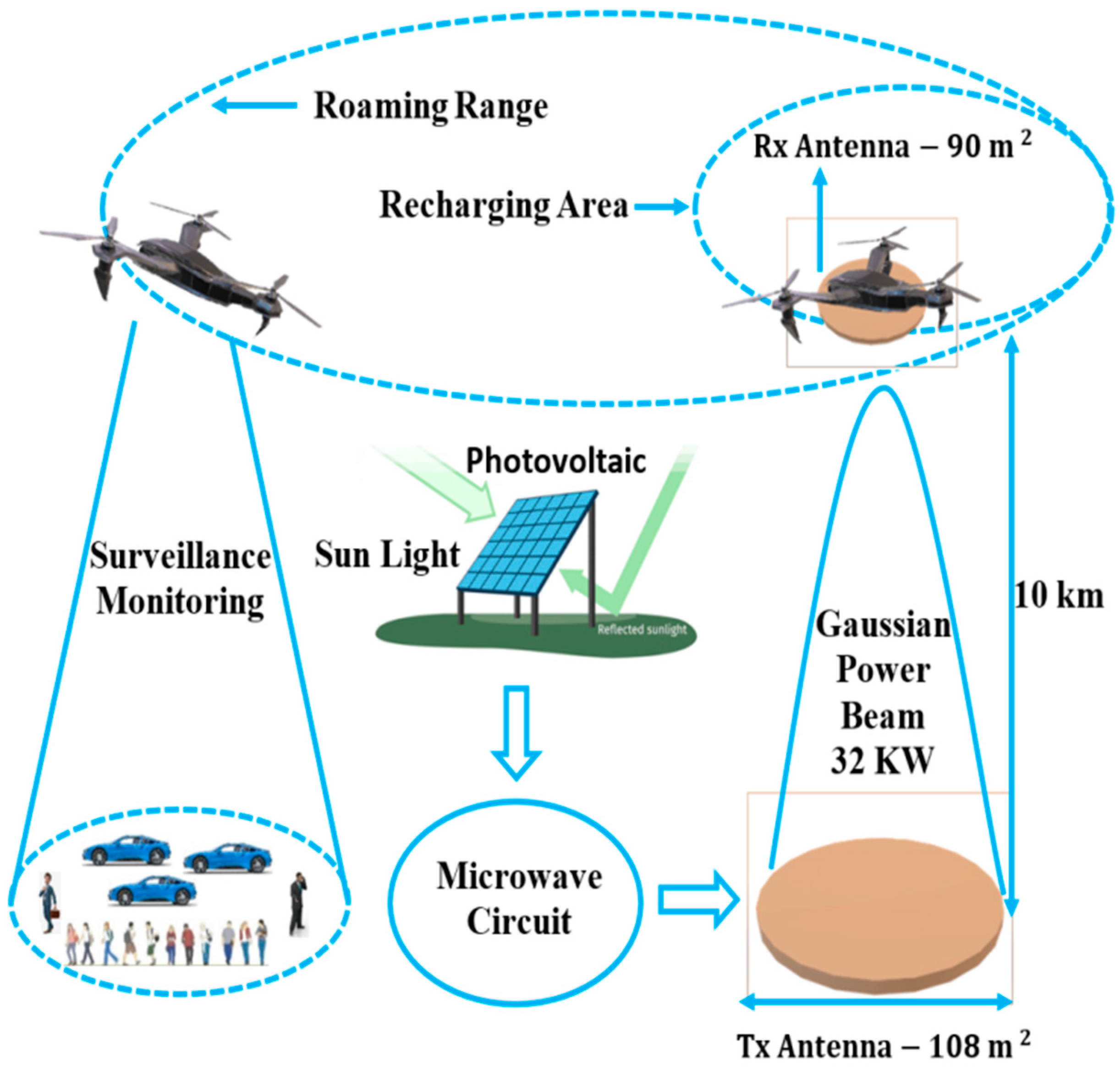
2. Remotely Powered Unmanned Air Vehicles

A key problem with conventional UAV is the limited amount of energy that can be stored onboard [34,35]. In order to increase the mission roaming range, the amount of energy stored needs to be increased at the expense of increased battery weight. One way to counter this problem is by supplying power remotely during the flight enabling recharge during the mission. Additionally, using microwave energy transmission allows the transfer over several kilometers and extends at the same time the roaming range. The most significant advantage of microwave power transmission technology is the capability for long-distance non-contact power transmission [11]. Wireless power transfer using microwaves is now a mature technology, and it can be utilized for efficient remotely powered UAV systems.

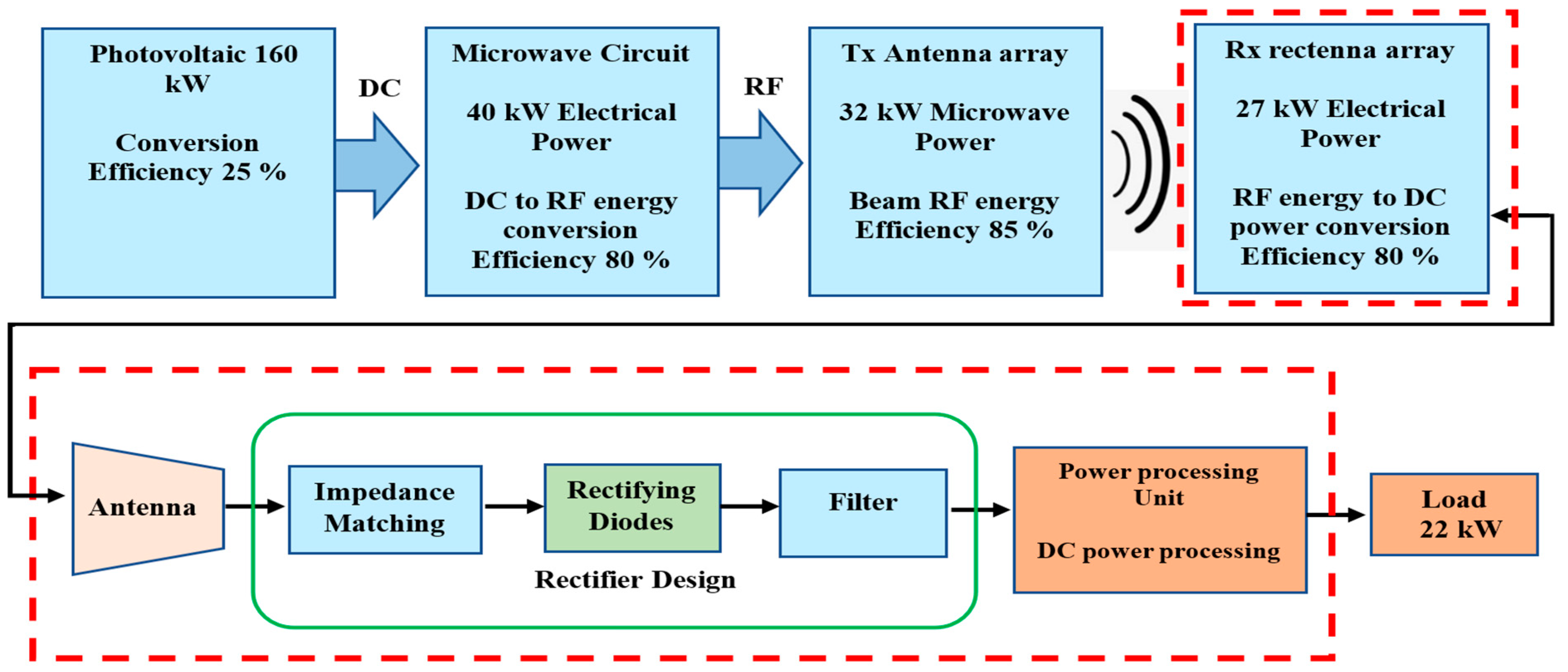
2.1. Proposed System Architecture

Pioneer works in that field were initiated many years ago by SHARP [17], wherein a high-altitude microwave-powered airplane was considered as a platform for relaying telecommunication signals. The idea includes a large ground antenna transferring microwave power to fuel-free airplanes at an altitude of 21 km [14,15,16,17,18,19,20,21]. This microwave power captured by the rectenna mounted under the airplane is converted into usable DC power to run the electric motor. Sharp has performed both theoretical and experimental analysis in this project, and the ISM frequency of 2.45 GHz was used [17]. Here, we proposed a microwave-powered UAV, at a transmitting distance of 10 km from the ground station. The transmitting distance can be varied according to the power demand. The proposed system architecture is shown in Figure 1. In this project, the MGM Compro electric propulsion system is adopted using a brushless DC motor with an embedded controller. It has maximum ratings in continuous power, voltage, torque, and revolution of 22 kW, 120 V, 100 Nm, and 8000 RPM, respectively. The UAVs can fly to the surveillance or monitoring area beyond the WPT range using its installed battery power of 120 V and 200 Ah. When the battery power goes down below a certain threshold, the UAV flies back within the WPT range (rechargeable area) for recharging. Several UAVs could use the same WPT ground station [1]. The ground station Tx antenna transmits power to the Rx rectenna mounted under the UAV while flying in the recharging area.
The beam direction of the transmitted signal is determined by a pilot signal tracking method [36]. A large Tx and Rx antenna system is required with higher transmission efficiency for the successful MPT. Therefore, phase synchronization becomes an important issue among the unit. Hence, beam steering can be applied in each unit to solve the phase error. When the UAV changes its direction, the direction of the main lobe of the radiation pattern is changed in the Tx system in order to follow the UAV. The wingspan and length of the UAV are 10 m and 9 m, respectively. Therefore, the maximum antenna area on the UAV is 90 m2. Given this antenna size, a maximum power, P T , of 27 kW can be transmitted according to the equation:
P T = P d × A eff
where P d is the beam power density safety limit for microwave on earth atmosphere set to 300 W/m2 [37], and A eff is the antenna effective area. The impact of the Rx antenna on the UAV’s aerodynamics is not considered here as it is beyond the scope of this paper. However, a major redesign of the aircraft could be required.

2.2. Selection of the 35 GHz Transmission Frequency

In point-to-point microwave power transfer, the first step is selecting a suitable frequency in the microwave band. Hence, industrial, scientific, and medical (ISM) frequency bands of 2.45 GHz, 5.8 GHz, and 24.5 GHz are recommended for MPTs [38,39]. On the other hand, the Tx antenna and Rx rectenna dimension increase with the transmitting distance. As a result, for long-distance power transmission, the dimensions of the transmitter and the receiver would be very large and costly for the ISM frequency bands. To decrease the antenna dimensions and to lower the cost, higher frequencies, i.e., 35, 61, and 94 GHz, are preferable. Among them, the 35 GHz frequency is chosen for MPT in this research. This frequency window decreases the Tx antenna and the Rx rectenna dimension while keeping a transmission efficiency in the order of more than 90% [40]. Atmospheric absorption loss is also low at this frequency window [41].

3. Microwave Wireless Power Transmission

There are many key issues for deploying microwave-powered UAVs. Wireless power transfer for a distance of more than 10 km is a challenging task; the Gaussian beamforming technique must be used for efficient transmission [11,42]. A 32-kW microwave UAV power flow diagram is shown in Figure 2. In this proposed system, photovoltaic arrays transform solar power into electrical power (DC). The high voltage DC power is then supplied to a microwave generator, i.e., a magnetron that delivers the transferred microwave power [43]. The beam formation is achievable using a phased array antenna [44,45]. The receiving microwave antenna connected with the rectifier changes the high-frequency microwave power back to electrical DC power [46]. In this model, a solar array is required for collecting 160 kW of solar insolation at a power density of 1000 W/m2 and produces 40 kW DC power (25% conversion efficiency). Considering a DC-to-microwave conversion efficiency of 80% [47,48], 32 kW microwave power would be transmitted from the ground Tx antenna. Here, our target is to design a suitable rectenna to power the 22-kW electrical propeller onboard the UAV.

Microwave Wireless Power Transmission Equations

Equation (2) shows the Friis’ relationship for transmitted signal within the far-field Fraunhofer zone.
P R = P T G T   ( λ 4 π D ) 2 G R = A t A r λ 2 D 2 P T  
where P T and P R are transmitted and received power, G T and G R are the gain, and A t and A r are the effective surface area of the Tx antenna and Rx rectenna, respectively. D is the separation between the Tx antenna and the Rx rectenna and λ is the transmitted wavelength. This transmission equation is not applicable for long-distance, point-to-point power transfer because, in the Fraunhofer zone, the beam power density decreases as the square of the distance between the Tx and the Rx antennas. As a consequence, full dispersion occurs [38]. In order to obtain efficient power at the receiving antenna, a near-field zone needs to be considered, wherein the beam power density remains constant with respect to distance, and the dispersion is also negligible [11,38]. G. Goubau and W.C. Brown showed the relationship between wireless beam power transfer efficiency and beam power transmission parameter for near field conditions in Equations (3) and (4) [11,42].
A t A r λ 2 D 2 = τ 2
where τ is the beam transmission parameter.
Then, the beam transmission efficiency is given by:
η beam = 1 e τ 2
Figure 3a shows the beam transmission efficiency as a function of the beam transmission parameter. According to Figure 3a, a 100% beam transmission efficiency is achievable at a transmission parameter of 2.5 [16,17]. Figure 3b shows the Tx antenna aperture variation as a function of the beam efficiency and the transmission distance, as obtained from Equations (3) and (4). As expected, a larger antenna area is required for long-distance power transmission and higher beam transfer efficiency, assuming A r   A t .

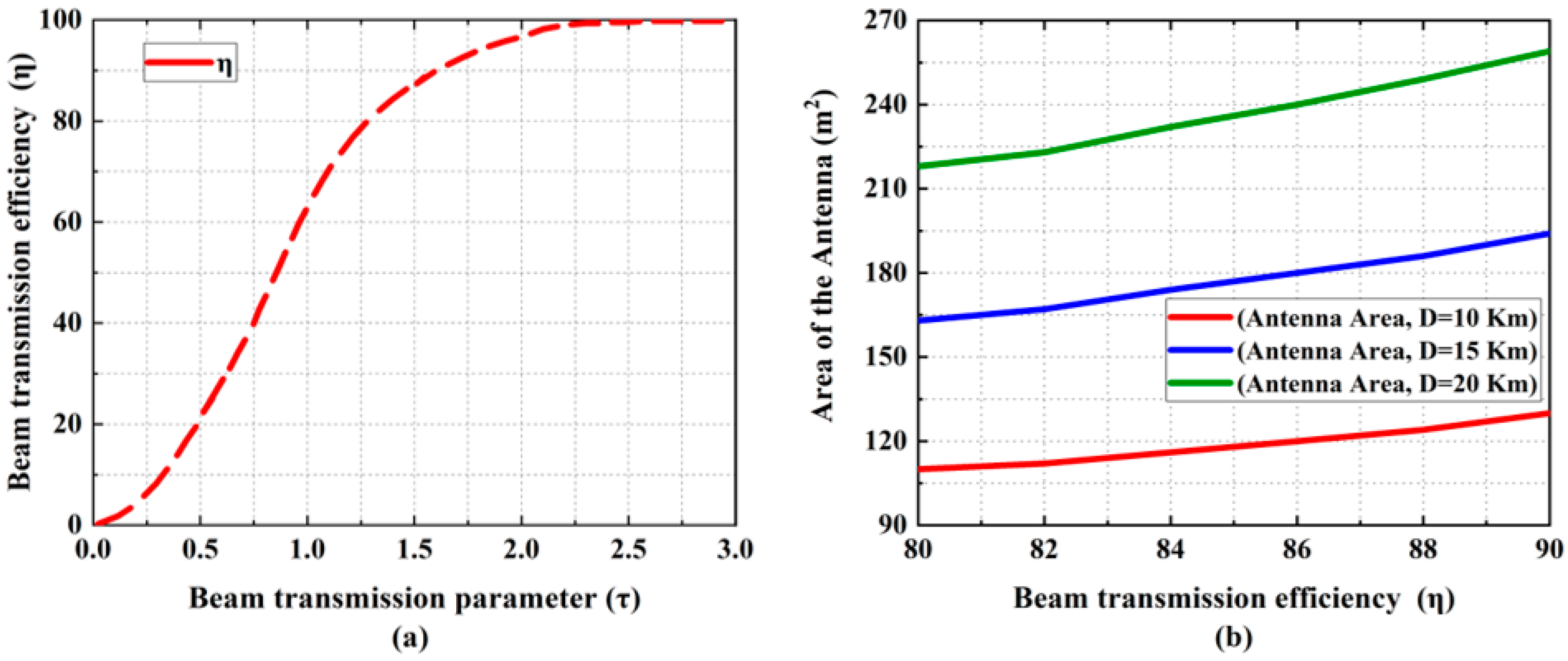
4. Tx Antenna Area Calculation for Different Power Level

Knowing the Tx antenna dimension, it is then possible to calculate the power transmission capacity of the Tx antenna and the power receiving capacity of the Rx rectenna using Equation (1). First, the area of the Tx antenna needs to be calculated using Equations (3) and (4) and considering a 10 km transmission distance at 35 GHz signal frequency. In that case, if we consider a reasonable beam transmission efficiency of 80%, we obtain τ = 1.26 , which allows us to extract the required antennas’ area ( A r   A t ) , using the same calculation method as the one used of the Tx antenna size. Different power transmission distances are shown in Figure 4a. For the desired 10 km power transmission distance, A r   A t =   108   m 2 is found, which is the minimum size required to maintain near-field conditions. The Tx antenna power capacity variation with the size is given in Figure 4b; it can be noticed here that an antenna size of 108   m 2 is able to transmit 32 kW of power according to Equation (1).
Now, using Equation (1), it is possible to calculate the maximum power transmission capacity of the Tx antenna. For instance, when the Tx antenna area is 108 m2 and the beam power density is 300 W/m2 [37], given the safety and security limits, the maximum power transmission capacity of the Tx antenna is 32 kW. If the area of the antenna increases, then it can transmit more power and more distance as well, as shown in Figure 4b. The area of the selected UAV is 90 m2 and a rectenna of the same size can receive 27 kW RF power and convert it to usable DC power to feed the electric motor of the propeller.
A comparison with previous MPT work is presented in Table 1. With the advancement in microwave technology, the operating frequency can be increased for a cost-effective and highly efficient MPT system.

5. Design and Simulation of Microstrip Patch Antenna Array

A high gain and high directivity antenna is required for MPT applications. Moreover, an array of antennas has more gain and directivity compared to a single antenna. Therefore, an array of patch antennas is selected for the project. Patch antennas have excellent radiation characteristics and are easier to design and fabricate. In addition, they are light in weight, compact, have a low fabrication cost, and have small dimensions.

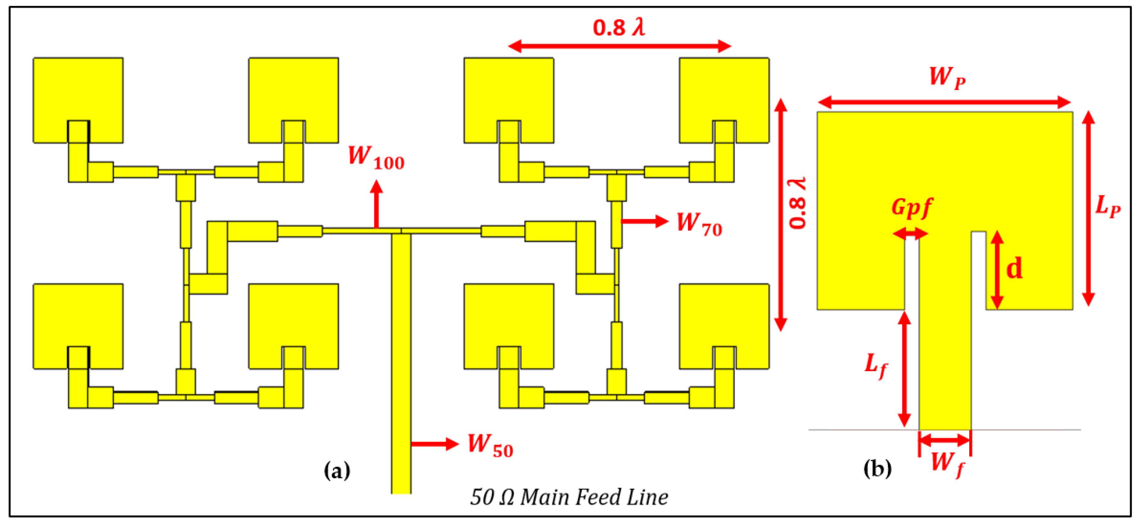
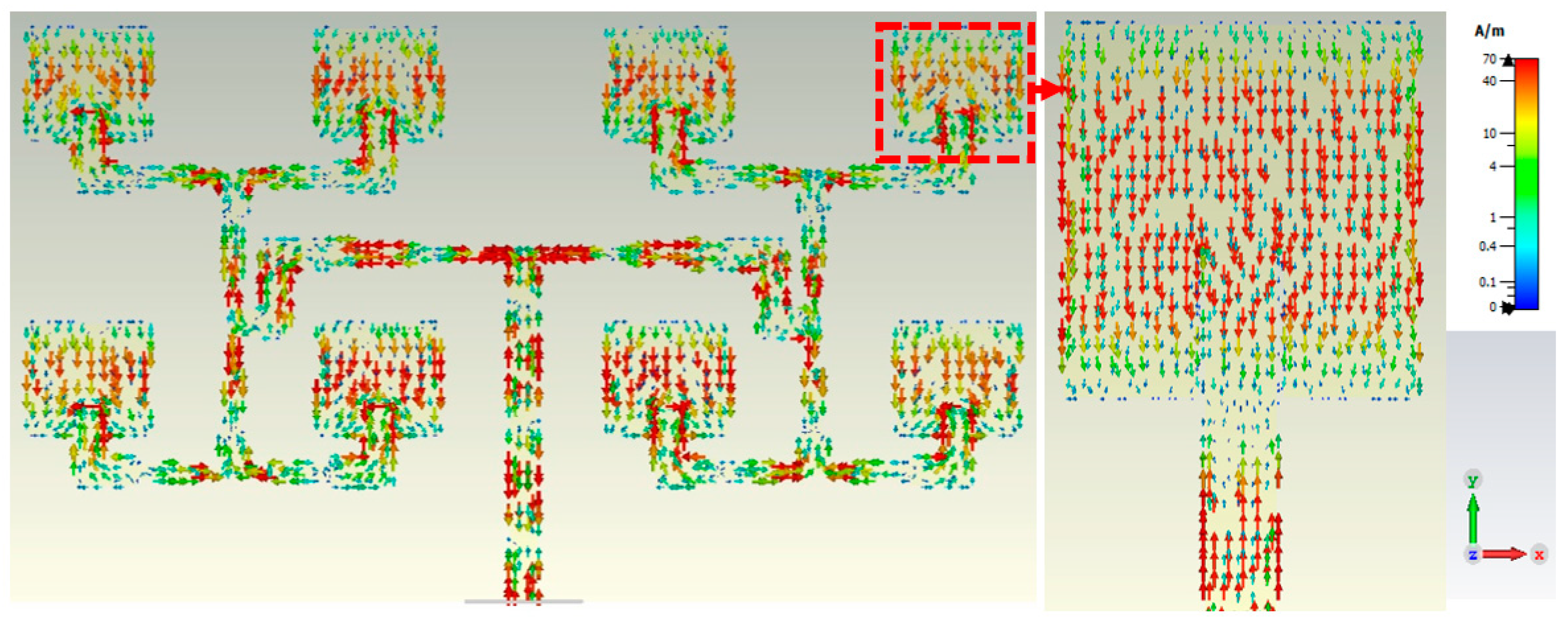
5.1. 4 × 2 Patch Antenna Array Design

The geometry of the proposed 4 × 2 patch antenna array is shown in Figure 5. The proposed antenna is designed on a RT-Duroid substrate with a thickness of 0.254 mm, a dielectric constant of 2.2, and a loss tangent of 0.0004 to 0.0009. Copper is selected as the top and bottom conductor layers because of its low cost and high conductivity. The copper thickness is 0.0035 mm. The bottom conductor can work either as an RF ground or a reflection plane.
The design and simulation of the microstrip patch antenna array are carried out using the corporate feed network since the incident power can be distributed equally to each antenna element from a single power port. The 4 × 2 microstrip patch antenna arrays are designed and optimized with the software tool CST Studio Suite.

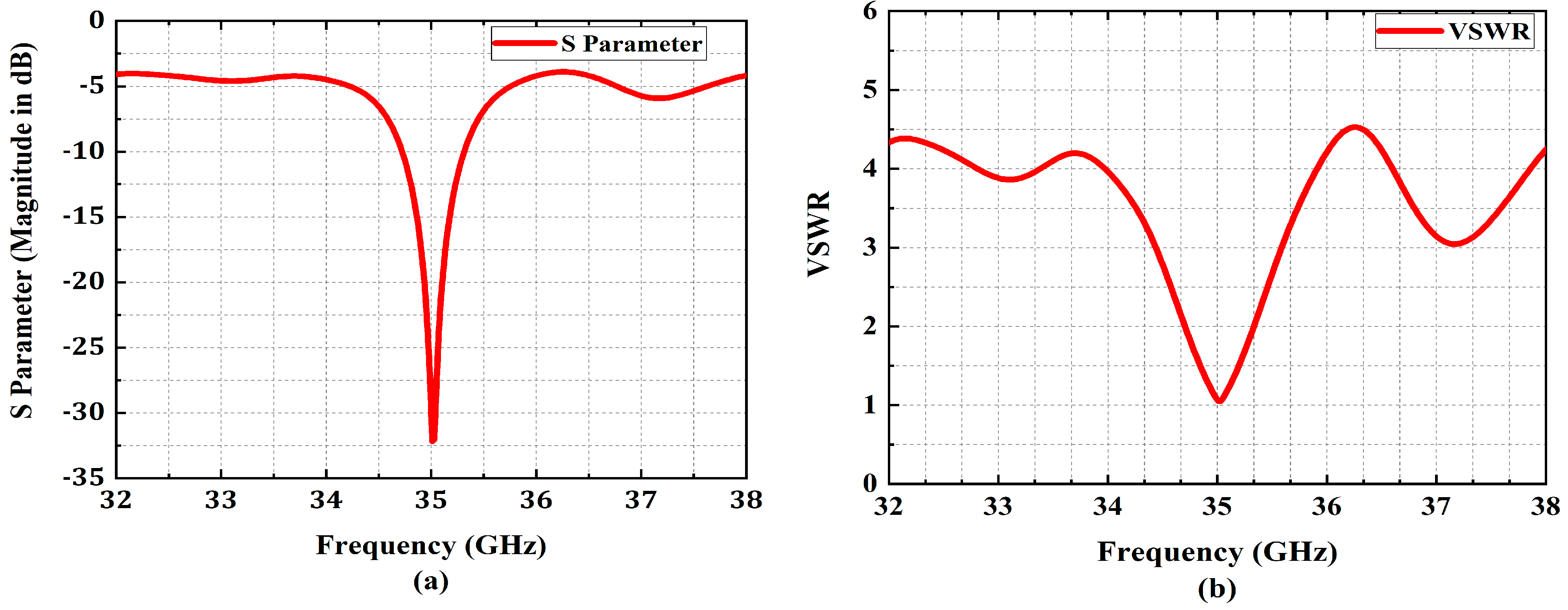
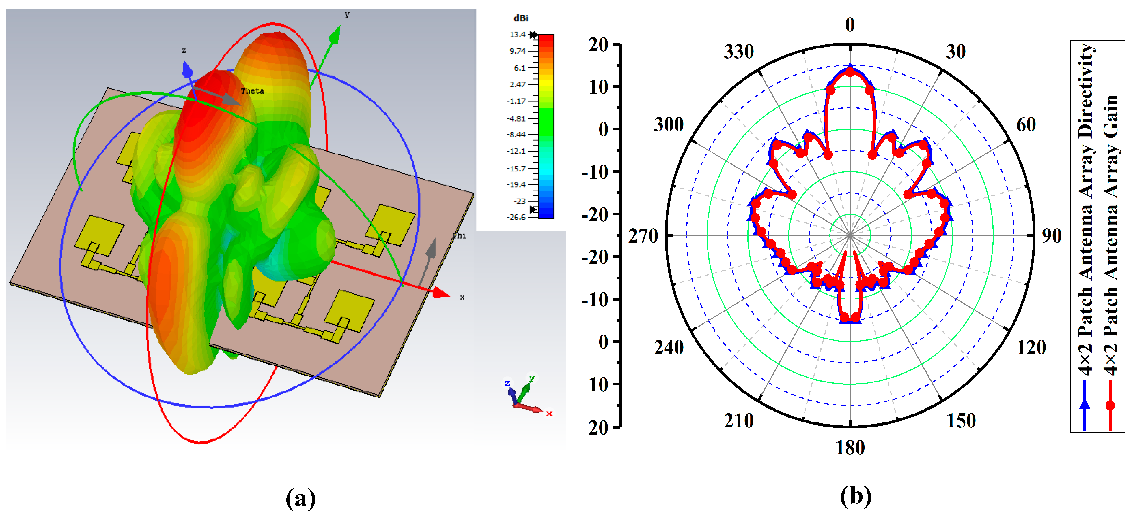
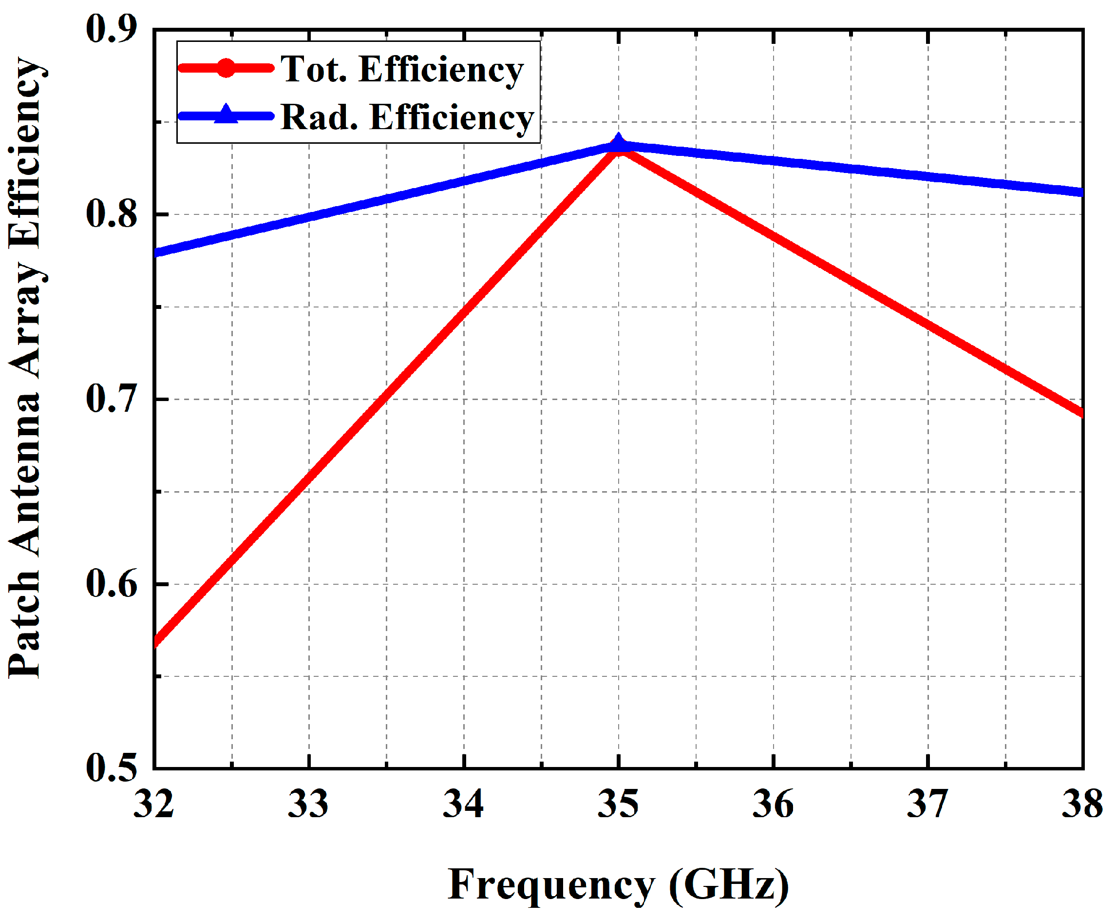
5.2. Results and Discussion

At 35 GHz, the surface current flow of a 4 × 2 patch antenna array is shown in Figure 6. The designed antenna is linearly polarized and found to be suitable for point-to-point power transfer. The return loss of the designed patch antenna array is shown in Figure 7a. This antenna resonates well at a desired 35 GHz center frequency with a reflection coefficient value of −33 dB. The bandwidth of the antenna at −10 dB is 0.7 GHz. The ratio of maximum and a minimum standing wave is called VSWR. Figure 7b shows a VSWR of 1.06 at the center frequency of 35 GHz. Hence, the designed 4 × 2 patch antenna array can transfer high power.
Figure 8a shows the radiation pattern of the 4 × 2 antenna array. The intensity of the color corresponds to the energy level. The maximum energy is passing through the main lobe, and it has the highest gain and directivity. Figure 8b shows the 2D polar plot of the radiation diagram. The gain and directivity at 0 degree of the 4 × 2 antenna are 13.4 dBi and 14 dBi respectively, whereas the side lobes are less than −11 dBi. Hence, we can claim that the designed 4 × 2 antenna array has satisfactory features for an MPT. The designed 4 × 2 microstrip patch antenna array has an efficiency of 85%, as shown in Figure 9.

6. Design and Optimization of Rectifying Circuit

A rectenna typically consists of an antenna, a diode, a matching circuit, and a resistive load (RL) connected to the end of the circuit to collect the DC power, as shown in Figure 10. It has various topologies based on the diode orientation such as series [51,52,53], shunt [54,55], voltage doubler, and bridge rectifier [56,57]. A voltage doubler rectifier topology is selected for this project in order to achieve a higher RF to DC conversion efficiency.

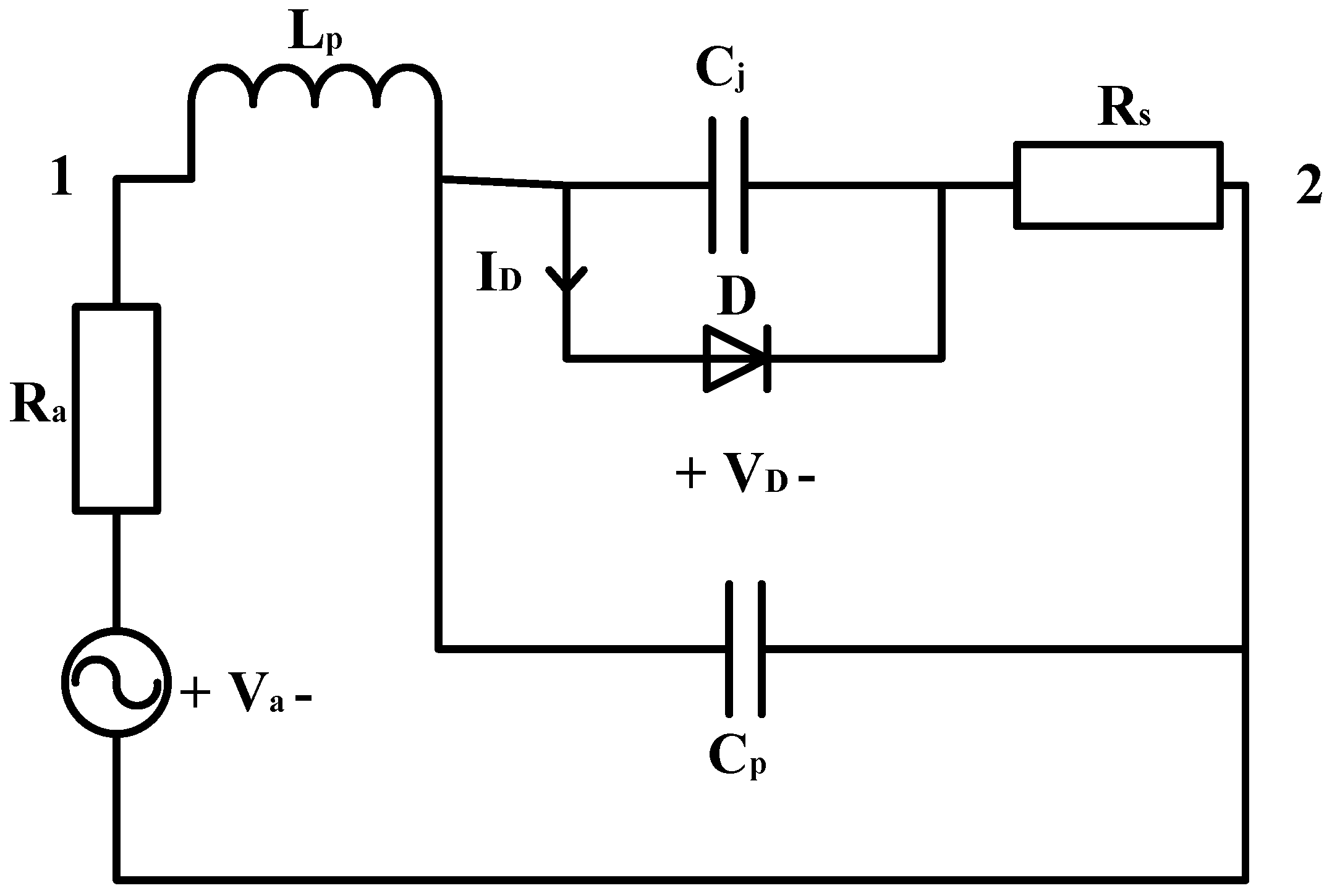
6.1. Equivalent Circuit Model of a Schottky Diode

The Schottky diode is a nonlinear device, as proved analytically in [58,59,60] and verified in [61,62]. The circuit analysis presented in [61] is a standard technique that is quick, precise, and reliable for calculating the input impedance of the packaged Schottky diode as a function of the operating frequency and input power levels. The Schottky diode equivalent circuit model is shown in Figure 11. Here, Cj is the junction capacitance, and Cp and Lp are the parasitic packaging capacitance and inductance, respectively. D is the ideal diode, Va is an RF voltage source, and Ra is the internal resistance of the source and series resistance Rs.
In Figure 11, Kirchhoff’s current and voltage laws are used to determine the voltage VD and current ID across the diode D. These found values are further used to determine the impedance of the rectifier. A voltage source with a single frequency f 0 as input, V a = | V a |   cos   ( 2 τ r f 0 t ) , is used as shown in Figure 11. The electrical behavior of this circuit can be described with the following expressions, found by applying Kirchhoff’s relations:
V a = I a R a + L p I a t + V C P
V C P = V D + V R S
V R S = R s ( I C j + I D )
I C j = C j V D t  
I D = I s ( e α V D 1 )
so that,
V D t = 1 R s C j { ψ ( I a t ) R s I s ( e α V D 1 ) }
where,
ψ ( I a t ) = V a R a I a V D L p I a t , α = q n K T
q K T is the thermal voltage and n is the ideality factor. The above differential Equation (10) has been solved with the fourth-order Runge–Kutta method and the voltage V D across the diode, D, is calculated. Furthermore, Equation (9) is used to determine the current I D flowing through the diode. After the evaluation of V D and I D , the input impedance of the diode D is found using Ohm’s law:
Z D = V D I D  

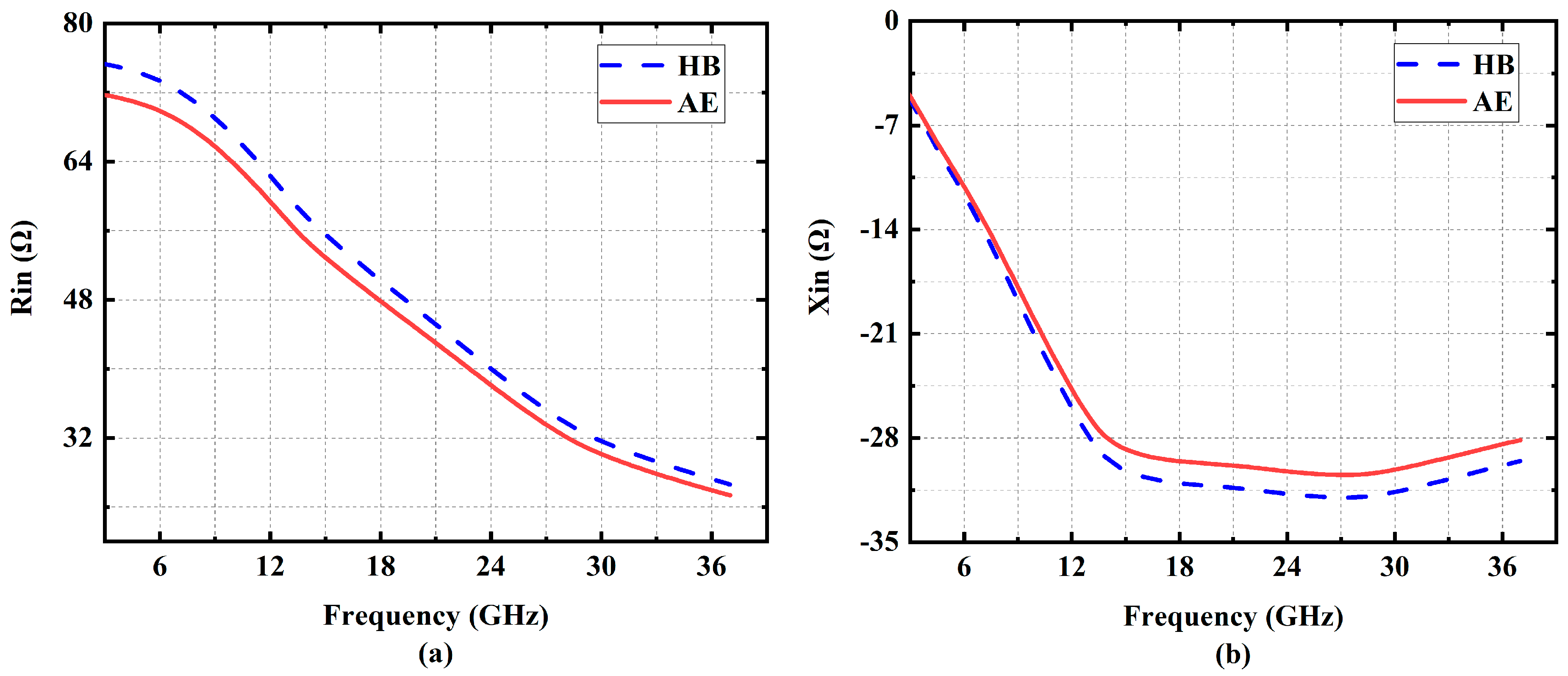
Harmonic Balance (HB) Simulation Validation

The Spice model parameters of the MA4E1317 diode are found in [59,63], where the ideality factor N = 1.5, the grading coefficient M = 0.5, the saturation current Is = 100 nA, the series resistance Rs = 4 Ω, the junction capacitance Cjo = 0.02 pF, the parasitic capacitance Cp = 0.025 pF, parasitic inductance Lp = 0.05 nH, the reverse breakdown voltage Vbr = 7 V, and the forward voltage Vf = 0.6 V, at forward current If =1 mA. Using the values of Spice parameters, the input impedance of the Schottky diode Z in including its series resistance and packaging parasitics is calculated. To verify the accuracy of the equivalent circuit model, the Schottky diode MA4E1317 ADS harmonic balance simulation model will be compared. The input impedance versus frequency for different power levels is calculated with the aid of the equivalent circuit model and is compared with harmonic balance simulation results.
Figure 12a,b shows the impedance of the rectifier as calculated by using ADS harmonic balance simulations and the presented analytical expressions (AE). Figure 12 also shows the real and imaginary parts of the input impedance versus frequency at an input power level of 10 dBm.
It is shown in Figure 12 that the equivalent circuit model can predict the impedance of the rectifier with a relative difference of less than 10% for the real and imaginary parts of the input impedance. The input impedance is again calculated using ADS harmonic balance simulations and the equivalent circuit model. It is shown in the figures that the results of the analytical equations are matching the results obtained using harmonic balance simulations.

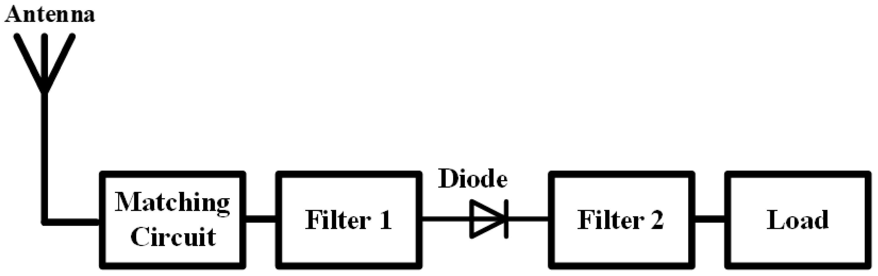
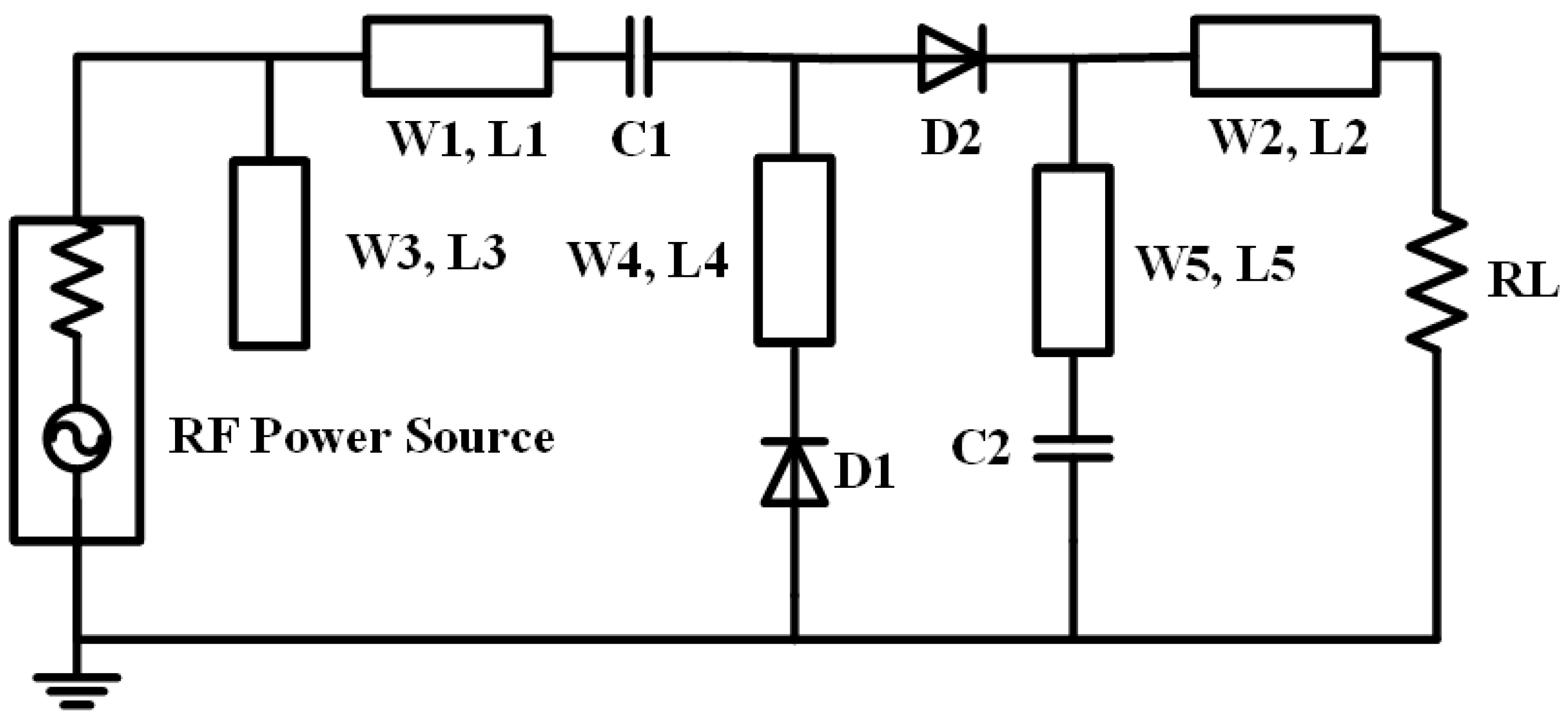
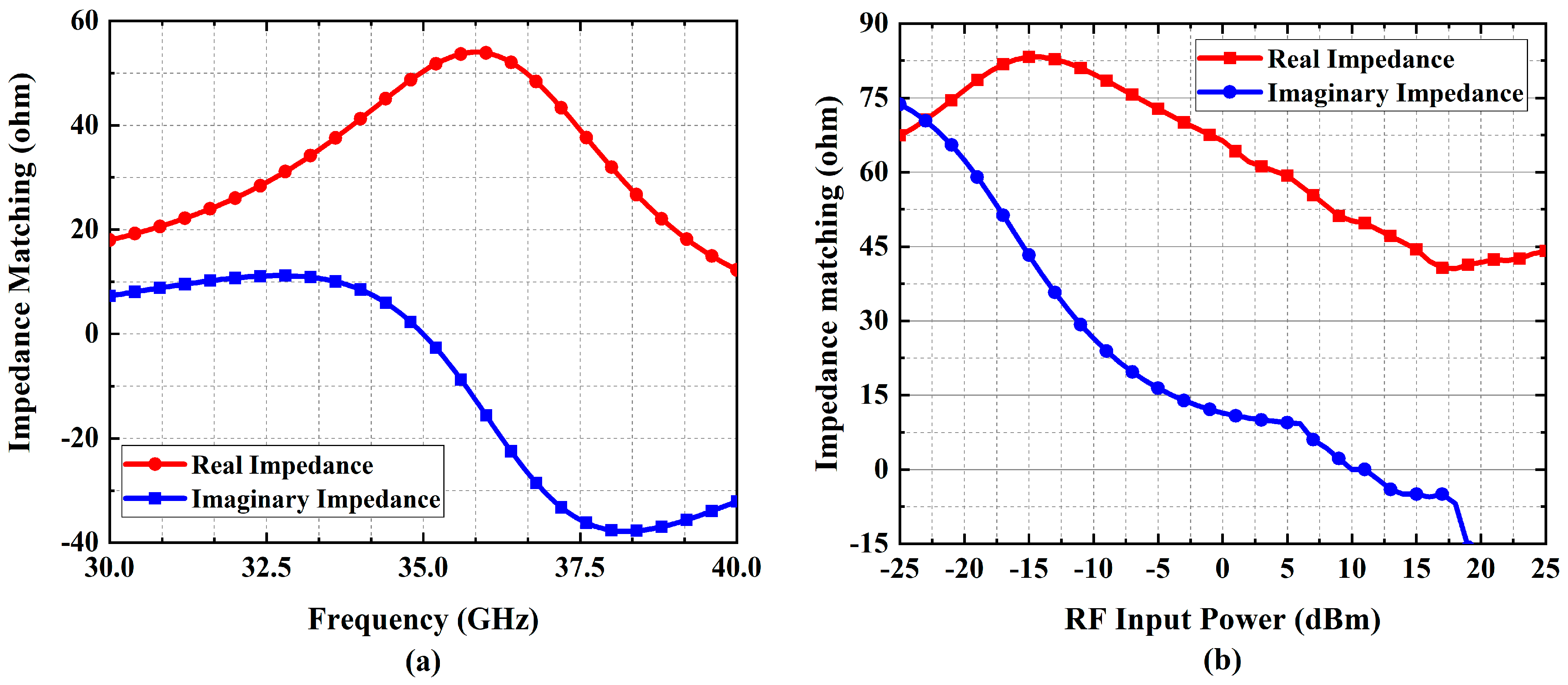
6.2. Rectifying Circuit Configuration

The geometrical structure of the proposed rectifying circuit operating at 35 GHz is shown in Figure 13. The rectifying circuit is designed on RT-Duroid substrate thickness of 0.254 mm, a relative dielectric constant of 2.2, and a loss tangent of 0.0004 to 0.0009.
The rectifying nonlinear circuit simulation is performed in Advance Design System (ADS) Harmonics Balance (HB) simulator. A 10 dBm input RF power was considered for the simulation. The circuit parameters are first calculated, and then the software ADS Optim toolbox with optimization-type genetic and iteration 500 can be utilized to optimize those parameters. After optimization, the parameters found are given in the Figure 13 caption.

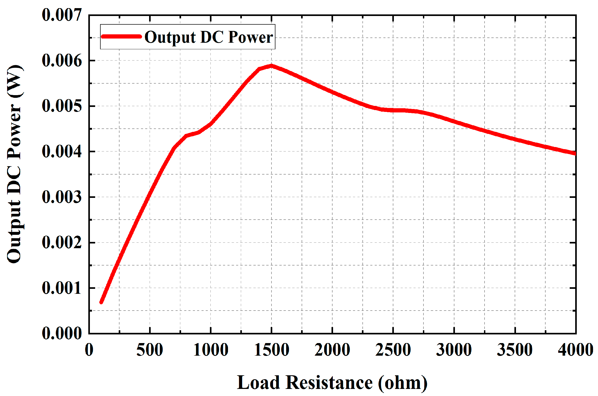
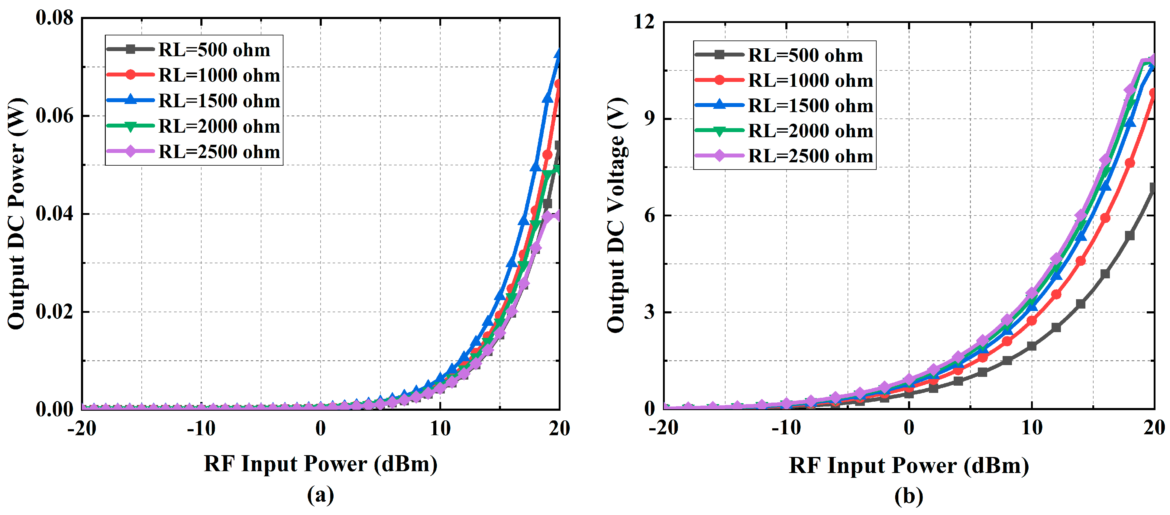
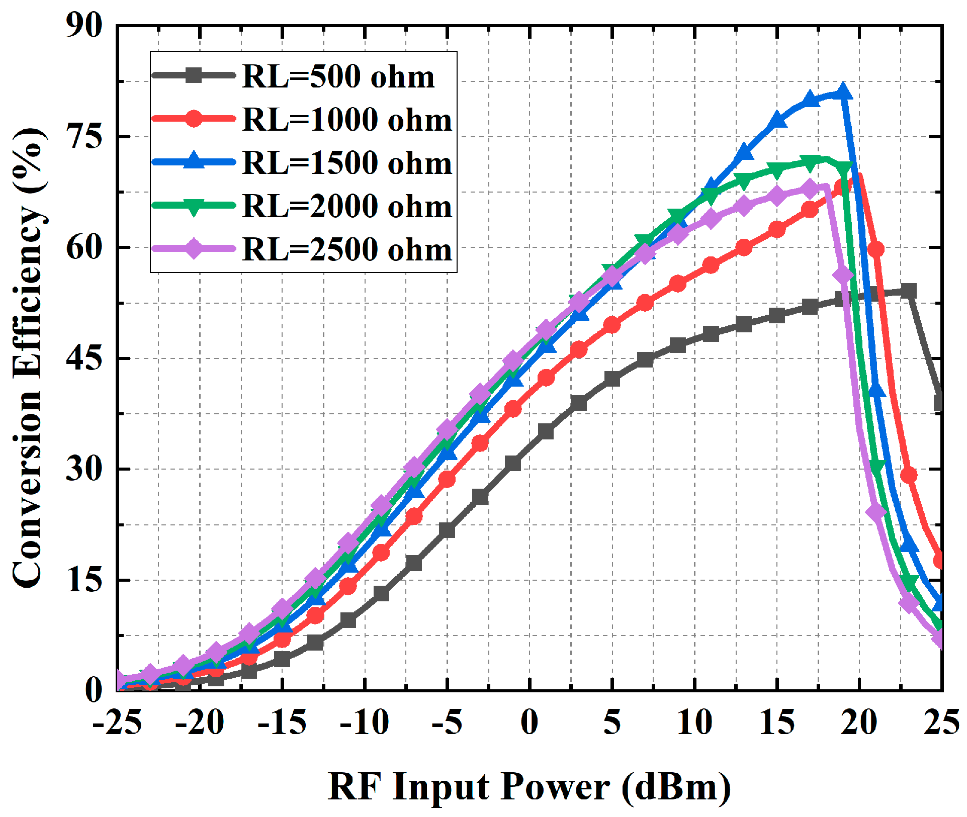
6.3. Results and Discussion

The output DC power changing across the different load resistors is shown in Figure 14. The maximum output DC power is obtained at 1500 Ω. Figure 15 exhibits the DC output power (a) and voltage (b) as a function of the input RF power with different load resistances (RL). At the desired input power of 10 dBm, a maximum 0.0065 W DC power and 3.1 V are achieved with an operating frequency of 35 GHz across the 1500 Ω load resistance.
Figure 16 shows the RF-to-DC conversion efficiency with various load resistances and different RF input power levels at the selected 35 GHz frequency. The figure depicts that the maximum efficiency of 82% is observed at 19 dBm input power with a 1500 Ω load resistance, whereas, at our desired power level of 10 dBm, an efficiency of 65% is achieved. However, the maximum efficiency was expected to be at 10 dBm input power; the reason behind this undesired behavior might be the impedance mismatch between the source power and the rectifier circuit. The RF-to-DC conversion efficiency of the rectenna can be determined using the following equation:
η = V o u t 2 P i n   R L × 100 %  
where V o u t is the output DC voltage, R L is the load resistance, and P i n is the input RF power.
The ADS Smith chart tool is then utilized to match the impedance at 35 GHz frequency with 10 dBm input power. The source power impedance is 50 Ω and the rectifier impedance can be determined by the commercial software ADS [64,65,66]. The rectifier input impedance’s real and imaginary value variation with frequency (GHz) and input power (dBm) are provided in Figure 17a,b, respectively. The impedance is matched to a 50 Ω load at the selected 35 GHz frequency.
After impedance matching (IM), the output DC power and voltage are improved; consequently, the RF-to-DC conversion efficiency is also improved. A comparison between the proposed rectenna with and without impedance matching is presented in Figure 18. The rectenna without IM has a maximum efficiency of 82% at 19 dBm. The proposed rectenna has a plateau in the efficiency curve at an RF input power range of 9 to 18 dBm, and the average efficiency is greater than 80% in that range. Table 2 compares the efficiency of the proposed rectenna with related works. The reported 80% is higher than all other identified prior works.

6.4. Large Area Power Collection

This work considers an onboard rectenna that could benefit from mass production, easy interconnections, and integration with power electronics circuitry. The power capacity of a single rectenna is low; therefore, to fulfill the high power demand, there is a requirement for series and parallel combinations. In previous works [72,73], it has been shown that series connection offer more power losses than parallel connections, so optimum connection of series/parallel is required for maximum power transfer; otherwise, losses will be high and will contribute to heating issues. Additionally, supplying maximum power for battery charging of the UAV is a challenging task. It is due to the fact that energy storage units such as rechargeable batteries or supercapacitors do not have the voltage/current characteristics of a resistor. This problem can be solved by using a cost-effective and efficient resistance emulation technique as proposed in [74]. First, a module will be developed with optimum rectenna array connection and integrated power circuitry. To determine the optimum module size, power simulation, thermal modeling and simulation will be performed. ADS has an integrated circuit and EM solver (co-simulation) and thermal solver (path-wave) that can be found suitable to determine the optimum module size. The onboard design will be assembled to form a module. Furthermore, these modules combine power and form an assembly to supply the maximum power to the load, as shown in Figure 19.
The designed 4 × 2 antenna is directly attached to a rectifier circuit in a single rectenna. The effective area of the designed 4 × 2 antenna is 0.000128 m2, which can transmit or receive 38.4 mW for RF power at a density of 300 W/m2 according to Equation (1). A suitable optimum combination of 74,000 rectenna elements can assuming, a rectenna RF–DC conversion efficiency of 80% and an array efficiency of 85%.
According to our system described in Section 2, an Rx antenna area of 90 m2 can accommodate 74,000 rectenna elements. The UAV is handling high power that is wirelessly transmitted via microwave while maintaining a lower operating temperature has proven effective in preventing power loss as well as component degradation. The thermal problem can be countered by applying a suitable cooling method, and then the thermal management systems are analyzed in [75].

7. Conclusions

The concept of efficiently transmitting 22 kW of DC power to a UAV using microwave over a distance of 10 km has been presented. The underlying system architecture of UAVs is based on a 35 GHz microwave signal that allows reducing the antenna size while keeping a high transfer efficiency over long distances. An array of microstrip patch antennas is adopted for the transmitting system. It is composed of 4 × 2 rectangular microstrip patches that have been optimized using a CST tool. The numerically simulated gain, directivity, and efficiency of the proposed 4 × 2 microstrip patch antenna are 13.4 dBi, 14 dBi, and 85%, respectively. The optimized value of Tx areas and beam efficiency are, respectively, 108 m2 and 80% to transmit microwave power efficiently at a frequency of 35 GHz. Finally, to receive the microwave power, the Rx areas are optimized to 90 m2 and a rectenna is designed employing the Agilent advanced design system (ADS) software. The proposed rectenna has an efficiency of over 80% for an RF input power range of 9 to 18 dBm and a DC output voltage of 3.5 V for a 10 dBm input power at 35 GHz, feeding a load of 1500 Ω.

Author Contributions

Writing, M.U.H.; analysis and calculation, M.U.H.; array optimization, M.U.H.; antenna and rectenna design and simulation, M.U.H.; methodology, D.K.; proposed the main idea, Y.A.; writing—review and editing, D.K., Y.A. and Y.S.; supervision, Y.A., Y.S. and D.K. All authors have read and agreed to the published version of the manuscript.

Funding

This research was partially funded by MITACS and the Natural Sciences and Engineering Research Council of Canada.

Institutional Review Board Statement

Not applicable.

Informed Consent Statement

Not applicable.

Data Availability Statement

Not applicable.

Conflicts of Interest

The authors declare no conflict of interest.

References

  1. Loianno, G.; Spurny, V.; Thomas, J.; Baca, T.; Thakur, D.; Hert, D.; Penicka, R.; Krajnik, T.; Zhou, A.; Cho, A.; et al. Localization, grasping, and transportation of magnetic objects by a team of mavs in challenging desert-like environments. IEEE Robot. Autom. Lett. 2018, 3, 1576–1583. [Google Scholar] [CrossRef]
  2. Tomic, T.; Schmid, K.; Lutz, P.; Domel, A.; Kassecker, M.; Mair, E.; Grixa, I.; Ruess, F.; Suppa, M.; Burschka, D. Toward a fully autonomous UAV: Research platform for indoor and Outdoor Urban Search and rescue. IEEE Robot. Autom. Mag. 2012, 19, 46–56. [Google Scholar] [CrossRef] [Green Version]
  3. Keller, J.; Thakur, D.; Likhachev, M.; Gallier, J.; Kumar, V. Coordinated path planning for fixed-wing UAS conducting persistent surveillance missions. IEEE Trans. Autom. Sci. Eng. 2017, 14, 17–24. [Google Scholar] [CrossRef]
  4. Weiss, S.; Scaramuzza, D.; Siegwart, R. Monocular-SLAM-based navigation for autonomous micro helicopters in GPS-denied environments. J. Field Robot. 2011, 28, 854–874. [Google Scholar] [CrossRef]
  5. Ritz, R.; D’Andrea, R. Carrying a flexible payload with multiple flying vehicles. In Proceedings of the 2013 IEEE/RSJ International Conference on Intelligent Robots and Systems, Tokyo, Japan, 3–7 November 2013. [Google Scholar]
  6. Loianno, G.; Kumar, V. Cooperative transportation using small quadrotors using monocular vision and inertial sensing. IEEE Robot. Autom. Lett. 2018, 3, 680–687. [Google Scholar] [CrossRef]
  7. Bernard, M.; Kondak, K.; Maza, I.; Ollero, A. Autonomous Transportation and deployment with aerial robots for search and rescue missions. J. Field Robot. 2011, 28, 914–931. [Google Scholar] [CrossRef] [Green Version]
  8. Saska, M.; Baca, T.; Thomas, J.; Chudoba, J.; Preucil, L.; Krajnik, T.; Faigl, J.; Loianno, G.; Kumar, V. System for deployment of groups of unmanned micro aerial vehicles in GPS-denied environments using onboard visual relative localization. Auton. Robot. 2016, 41, 919–944. [Google Scholar] [CrossRef] [Green Version]
  9. Brown, W.C. A survey of the elements of power transmission by microwave beam. IRE Int. Conv. Rec. 1961, 9, 93–105. [Google Scholar]
  10. Brown, W.C. The Combination Receiving Antenna and Rectifier. In Microwave Power Engineering; Okress, E.C., Ed.; Academic Press: New York, NY, USA, 1968; Volume 2, pp. 273–275. [Google Scholar]
  11. Brown, W.C.; Eves, E.E. Beamed microwave power transmission and its application to space. IEEE Trans. Microw. Theory Tech. 1992, 40, 1239–1250. [Google Scholar] [CrossRef]
  12. Brown, W.C. The history of power transmission by Radio Waves. IEEE Trans. Microw. Theory Tech. 1984, 32, 1230–1242. [Google Scholar] [CrossRef] [Green Version]
  13. Curty, J.-P.; Declercq, M.; Dehollain, C.; Joehl, N. Design and Optimization of Passive UHF RFID Systems; Springer: New York, NY, USA, 2007. [Google Scholar]
  14. Brown, W.C. Free-Space Transmission. IEEE Spectr. 1964, 1, 86–91. [Google Scholar] [CrossRef]
  15. Brown, W.C. The microwave powered helicopter. J. Microw. Power 1966, 1, 1–20. [Google Scholar] [CrossRef]
  16. Glaser, P.E.; Brown, W.C. An Electrical Propulsion Transportation System for Low-Earth Orbit to Geostationary Orbit Utilizing Beamed microwave power. Space Sol. Power Rev. 1983, 4, 119–129. [Google Scholar]
  17. Schlesak, J.J.; Alden, A.; Ohno, T. A microwave powered high altitude platform. In Proceedings of the IEEE MTT-S International Microwave Symposium Digest, New York, NY, USA, 25–27 May 1988. [Google Scholar]
  18. Matsumoto, H.; Kaya, N.; Fujita, M.; Fujino, Y.; Fujiwara, T.; Sato, T. MILAX airplane experiment and model airplane. In Proceedings of the 11th ISAS Space Energy Symp, Hakone, Japan, 11–14 December 1993. (In Japanese). [Google Scholar]
  19. Kaya, N.; Matsumoto, H.; Akiba, R. Rocket Experiment METS Microwave Energy Transmission in Space. J. Space Power 1992, 11, 267–274. [Google Scholar]
  20. Shinohara, N.; Matsumoto, H. Dependence of DC output of a rectenna array on the method of interconnection of its array elements. Electr. Eng. Jpn. 1998, 125, 9–17. [Google Scholar] [CrossRef]
  21. Kaya, N.; Ida, S.; Fujino, Y.; Fujita, M. Transmitting antenna system for airship demonstration (ETHER). Space Energy Transp. 1996, 1, 237–245. [Google Scholar]
  22. Chiam, T.M.; Ong, L.C.; Karim, M.F.; Guo, Y.X. 5.8GHz circularly polarized rectennas using Schottky diode and LTC5535 rectifier for RF Energy Harvesting. In Proceedings of the 2009 Asia Pacific Microwave Conference, Singapore, 7–10 December 2009. [Google Scholar]
  23. Strassner, B.; Chang, K. 5.8-GHz circularly polarized dual-rhombic-loop traveling-wave rectifying antenna for low power-density wireless power transmission applications. IEEE Trans. Microw. Theory Tech. 2003, 51, 1548–1553. [Google Scholar] [CrossRef]
  24. Heikkinen, J.; Kivikoski, M. Low-profile circularly polarized rectifying antenna for wireless power transmission at 5.8 GHz. IEEE Microw. Wirel. Compon. Lett. 2004, 14, 162–164. [Google Scholar] [CrossRef]
  25. Ren, Y.-J.; Li, M.-Y.; Chang, K. 35 ghz rectifying antenna for wireless power transmission. Electron. Lett. 2007, 43, 602. [Google Scholar] [CrossRef]
  26. Ren, Y.-J.; Chang, K. New 5.8-GHz circularly polarized retrodirective rectenna arrays for wireless power transmission. IEEE Trans. Microw. Theory Tech. 2006, 54, 2970–2976. [Google Scholar]
  27. Suh, Y.-H.; Chang, K. A high-efficiency dual-frequency rectenna for 2.45- and 5.8-GHz wireless power transmission. IEEE Trans. Microw. Theory Tech. 2002, 50, 1784–1789. [Google Scholar] [CrossRef] [Green Version]
  28. McSpadden, J.O.; Fan, L.; Chang, K. Design and experiments of a high-conversion-efficiency 5.8-GHz rectenna. IEEE Trans. Microw. Theory Tech. 1998, 46, 2053–2060. [Google Scholar] [CrossRef]
  29. Collado, A.; Georgiadis, A. 24 GHz substrate integrated waveguide (SIW) rectenna for energy harvesting and wireless power transmission. In Proceedings of the 2013 IEEE MTT-S International Microwave Symposium Digest (MTT), Seattle, WA, USA, 2–7 June 2013. [Google Scholar]
  30. Ladan, S.; Wu, K. High efficiency low-power microwave rectifier for wireless energy harvesting. In Proceedings of the 2013 IEEE MTT-S International Microwave Symposium Digest (MTT), Seattle, WA, USA, 2–7 June 2013. [Google Scholar]
  31. Ladan, S.; Hemour, S.; Wu, K. Towards millimeter-wave high-efficiency rectification for wireless energy harvesting. In Proceedings of the 2013 IEEE International Wireless Symposium (IWS), Beijing, China, 14–18 April 2013. [Google Scholar]
  32. Chiou, H.-K.; Chen, I.-S. High-efficiency dual-band on-chip rectenna for 35- and 94-GHz wireless power transmission in 0.13-μm CMOS technology. IEEE Trans. Microw. Theory Tech. 2010, 58, 3598–3606. [Google Scholar]
  33. Epp, L.W.; Khan, A.R.; Smith, H.K.; Smith, R.P. A compact dual-polarized 8.51-ghz rectenna for high-voltage (50 V) actuator applications. IEEE Trans. Microw. Theory Tech. 2000, 48, 111–120. [Google Scholar] [CrossRef]
  34. Fujino, Y.; Fujita, M.; Kaya, N.; Kunimi, S.; Ishii, M.; Ogihata, N.; Kusaka, N.; Ida, S. A Dual Polarization Microwave Power Transmission System for Microwave propelled Airship Experiment. In Proceedings of the ISAP’96, Chiba, Japan, 24 September 1996; Volume 2, pp. 393–396. [Google Scholar]
  35. Ozawa, Y.; Tanaka, N.; Hakojima, H. Study of electric aircraft recharged by Beamed Microwave Power. In Proceedings of the 53rd AIAA Aerospace Sciences Meeting, Kissimmee, FL, USA, 5–9 January 2015. [Google Scholar]
  36. Belo, D.; Ribeiro, D.C.; Pinho, P.; Borges Carvalho, N. A selective, tracking, and power adaptive far-field wireless power transfer system. IEEE Trans. Microw. Theory Tech. 2019, 67, 3856–3866. [Google Scholar] [CrossRef]
  37. URSI White Paper on Solar Power Satellite (SPS) Systems and Report of the URSI Inter-Commission Working Group on SPS. 2007. Available online: https://www.ursi.org/files/ICWGReport070611.pdf (accessed on 10 June 2021).
  38. Gavan, J.; Tapuchi, S. Microwave Wireless-Power Transmission to High-Altitude-Platform Systems. Radio Sci. Bull. 2010, 2010, 25–42. [Google Scholar]
  39. Gavan, J.; Perez, R. Handbook of Electromagnetic Compatibility, 1st ed.; Academic Press: New York, NY, USA, 1995; Chapter 19; Volume 20. [Google Scholar]
  40. Yoo, T.-W.; Chang, K. Theoretical and experimental development of 10 and 35 GHz rectennas. IEEE Trans. Microw. Theory Tech. 1992, 40, 1259–1266. [Google Scholar] [CrossRef]
  41. Fingas, M.F. Oil Spill Science and Technology; Gulf Professional Publishing: Cambridge, MA, USA, 2017. [Google Scholar]
  42. Goubau, G.; Schwering, F. On the guided propagation of electromagnetic wave beams. IRE Trans. Antennas Propag. 1961, 9, 248–256. [Google Scholar] [CrossRef]
  43. Shinohara, N.; Matsumoto, H. Point to point Microwave power Transfer Experiments. Scr. Tech. Inc 1996, 116B, 648–653. [Google Scholar]
  44. Shinohara, N.; Kubo, Y.; Tonomura, H. Wireless charging for electric vehicle with microwaves. In Proceedings of the 2013 3rd International Electric Drives Production Conference (EDPC), Nuremberg, Germany, 29–30 October 2013. [Google Scholar]
  45. Park, I.; Lee, E.; Ku, H. Angle tracking automatic beamforming for Microwave Power Transfer Systems. In Proceedings of the 2020 IEEE Wireless Power Transfer Conference (WPTC), Seoul, Korea, 15–19 November 2020. [Google Scholar]
  46. Ladan, S.; Wu, K. 35 GHz harmonic harvesting rectifier for wireless power transmission. In Proceedings of the 2014 IEEE MTT-S International Microwave Symposium (IMS2014), Tampa, FL, USA, 1–6 June 2014. [Google Scholar]
  47. Shinohara, N. Beam efficiency of wireless power transmission via radio waves from short range to long range. J. Electromagn. Eng. Sci. 2010, 10, 224–230. [Google Scholar] [CrossRef]
  48. Chen, X.; Yang, B.; Shinohara, N.; Liu, C. A high-efficiency microwave power combining system based on frequency-tuning injection-locked magnetrons. IEEE Trans. Electron. Devices 2020, 67, 4447–4452. [Google Scholar] [CrossRef]
  49. Khang, S.-T.; Lee, D.-J.; Hwang, I.-J.; Yeo, T.-D.; Yu, J.-W. Microwave power transfer with optimal number of rectenna arrays for midrange applications. IEEE Antennas Wirel. Propag. Lett. 2018, 17, 155–159. [Google Scholar] [CrossRef]
  50. Yi, X.; Chen, X.; Zhou, L.; Hao, S.; Zhang, B.; Duan, X. A microwave power transmission experiment based on the near-field focused transmitter. IEEE Antennas Wirel. Propag. Lett. 2019, 18, 1105–1108. [Google Scholar] [CrossRef]
  51. Sun, H.; Guo, Y.; He, M.; Zhong, Z. Design of a high-efficiency 2.45-ghz rectenna for low-input-power energy harvesting. IEEE Antennas Wirel. Propag. Lett. 2012, 11, 929–932. [Google Scholar]
  52. Ren, Y.-J.; Chang, K. 5.8-GHz circularly polarized dual-diode rectenna and rectenna array for microwave power transmission. IEEE Trans. Microw. Theory Tech. 2006, 54, 1495–1502. [Google Scholar]
  53. Yoo, T.; McSpadden, J.; Chang, K. 35 GHz rectenna implemented with a patch and a microstrip dipole antenna. In Proceedings of the IEEE Microwave Symposium Digest MTT-S, Albuquerque, NM, USA, 1–5 June 1992. [Google Scholar]
  54. Akkermans, J.A.G.; van Beurden, M.C.; Doodeman, G.J.N.; Visser, H.J. Analytical models for low-power rectenna design. IEEE Antennas Wirel. Propag. Lett. 2005, 4, 187–190. [Google Scholar] [CrossRef]
  55. He, Q.; Liu, C. An enhanced microwave rectifying circuit using HSMS-282. Microw. Opt. Technol. Lett. 2009, 51, 1151–1153. [Google Scholar] [CrossRef]
  56. Cardoso, A.J.; de Carli, L.G.; Galup-Montoro, C.; Schneider, M.C. Analysis of the rectifier circuit valid down to its low-voltage limit. IEEE Trans. Circuits Syst. I Regul. Pap. 2012, 59, 106–112. [Google Scholar] [CrossRef]
  57. Lawrance, W.B.; Mielczarski, W. Harmonic current reduction in a three-phase diode bridge rectifier. IEEE Trans. Ind. Electron. 1992, 39, 571–576. [Google Scholar] [CrossRef]
  58. Gao, S.-P.; Zhang, H.; Ngo, T.; Guo, Y. Lookup-table-based automated rectifier synthesis. IEEE Trans. Microw. Theory Tech. 2020, 68, 5200–5210. [Google Scholar] [CrossRef]
  59. Gao, S.-P.; Zhang, H.; Guo, Y.-X. Analysis of mmwave rectifiers with an accurate rectification model. In Proceedings of the 2021 IEEE Wireless Power Transfer Conference (WPTC), San Diego, CA, USA, 1–4 June 2021. [Google Scholar]
  60. Fleri, D.A.; Cohen, L.D. Nonlinear analysis of the Schottky-barrier mixer diode. IEEE Trans. Microw. Theory Tech. 1973, 21, 39–43. [Google Scholar] [CrossRef]
  61. Keyrouz, S.; Visser, H.J.; Tijhuis, A.G. Rectifier analysis for radio frequency energy harvesting and Power Transport. In Proceedings of the 2012 42nd European Microwave Conference, Amsterdam, The Netherlands, 29 October–1 November 2012. [Google Scholar]
  62. Visser, H.J. Approximate Antenna Analysis for CAD; John Wiley & Sons Incorporated: Hoboken, NJ, USA, 2008. [Google Scholar]
  63. Ladan, S.; Akyel, C.; Wu, K. Simultaneous Wireless Power Transmission and Data Communication. Ph.D. Thesis, Ecole Polytechnique Montreal University, Montreal, QC, Canada, 2014. [Google Scholar]
  64. Zhang, F.; Liu, X.; Meng, F.-Y.; Wu, Q.; Lee, J.-C.; Xu, J.-F.; Wang, C.; Kim, N.-Y. Design of a compact planar rectenna for wireless power transfer in the ISM band. Int. J. Antennas Propag. 2014, 2014, 1–9. [Google Scholar] [CrossRef] [Green Version]
  65. Kuhn, V.; Lahuec, C.; Seguin, F.; Person, C. A multi-band stacked RF Energy Harvester with RF-to-DC efficiency up to 84%. IEEE Trans. Microw. Theory Tech. 2015, 63, 1768–1778. [Google Scholar] [CrossRef]
  66. Ladan, S.; Guntupalli, A.B.; Wu, K. A high-efficiency 24 GHz rectenna development towards millimeter-wave energy harvesting and wireless power transmission. IEEE Trans. Circuits Syst. I Regul. Pap. 2014, 61, 3358–3366. [Google Scholar] [CrossRef]
  67. Awais, Q.; Jin, Y.; Chattha, H.T.; Jamil, M.; Qiang, H.; Khawaja, B.A. A compact rectenna system with high conversion efficiency for wireless energy harvesting. IEEE Access 2018, 6, 35857–35866. [Google Scholar] [CrossRef]
  68. Zhang, Q.; Ou, J.-H.; Wu, Z.; Tan, H.-Z. Novel microwave rectifier optimizing method and its application in Rectenna designs. IEEE Access 2018, 6, 53557–53565. [Google Scholar] [CrossRef]
  69. Shinohara, N.; Nishikawa, K.; Seki, T.; Hiraga, K. Development of 24 GHz rectennas for Fixed Wireless Access. In Proceedings of the 2011 XXXth URSI General Assembly and Scientific Symposium, Istanbul, Turkey, 13–20 August 2011. [Google Scholar]
  70. Mavaddat, A.; Armaki, S.H.; Erfanian, A.R. Millimeter-Wave Energy Harvesting Using 4 × 4 Microstrip Patch Antenna Array. IEEE Antennas Wirel. Propag. Lett. 2015, 14, 515–518. [Google Scholar] [CrossRef]
  71. Chen, Q.; Liu, Z.; Cui, Y.; Cai, H.; Chen, X. A metallic waveguide-integrated 35-GHz rectenna with high conversion efficiency. IEEE Microw. Wirel. Compon. Lett. 2020, 30, 821–824. [Google Scholar] [CrossRef]
  72. Shinohara, N.; Matsumoto, H. Experimental study of large rectenna array for microwave energy transmission. IEEE Trans. Microw. Theory Tech. 1998, 46, 261–268. [Google Scholar] [CrossRef]
  73. Miura, T.; Shinohara, N.; Matsumoto, H. Experimental study of rectenna connection for Microwave Power Transmission. Electron. Commun. Jpn. (Part II Electron.) 2001, 84, 27–36. [Google Scholar] [CrossRef]
  74. Paing, T.; Shin, J.; Zane, R.; Popovic, Z. Resistor emulation approach to low-power RF Energy Harvesting. IEEE Trans. Power Electron. 2008, 23, 1494–1501. [Google Scholar] [CrossRef]
  75. Brown, W.C.; Raytheon Co. Rectenna Technology Program: Ultra Light 2.45 GHz Rectenna and 20 GHz Rectenna; Raytheon Co.: Waltham, MA, USA, 1987. [Google Scholar]
Figure 1. Proposed system architecture for microwave wireless power transmission.
Energies 15 00320 g001
Figure 2. Microwave power transmission system block diagram.
Energies 15 00320 g002
Figure 3. (a) Beam transmission efficiency as a function of the beam transmission parameter τ for optimum power-density distribution across the transmitting antenna’s aperture [11,38] and (b) Tx antenna aperture variation as a function of beam efficiency and transmission distance.
Energies 15 00320 g003
Figure 4. (a) Area of the Tx antenna with different power transmission distance considering Friis’ near field equation for a beam transmission efficiency of 80%. (b) Maximum power transmission capacity of the Tx antenna with respect to the area considering a Tx antenna size of 108 m2.
Energies 15 00320 g004
Figure 5. (a) Illustration of antenna elements with 0.8 λ horizontal and 0.8 λ vertical spacing in a 4 × 2 patch antenna array with corporate feed, widths of 50 Ω (W50), 70.71 Ω (W70.71) and 100 Ω (W100) transmission lines are 0.8 mm, 0.45 mm, and 0.25 mm, respectively. (b) Unit element antenna parameter are: W P 3.4   mm , L P 2.7   mm , W f 0.8   mm , L f 1.6   mm , d 1.07   mm and Gpf 0.1   mm .
Energies 15 00320 g005
Figure 6. Surface currents plot of the 4 × 2 patch antenna array at 35 GHz.
Energies 15 00320 g006
Figure 7. (a) Return loss and (b) voltage standing wave ratio (VSWR) of a 4 × 2 patch antenna array.
Energies 15 00320 g007
Figure 8. Radiation pattern of the proposed patch antenna array (a) 3D view of a 4 × 2 array and (b) 2D polar view of a 4 × 2 array.
Energies 15 00320 g008
Figure 9. Efficiency of 4 × 2 patch antenna array.
Energies 15 00320 g009
Figure 10. Block diagram of conventional rectenna.
Energies 15 00320 g010
Figure 11. Simplified circuit model of a diode [58,59,60,61,62,63].
Energies 15 00320 g011
Figure 12. Real and imaginary parts of the input impedance of the Schottky diode MA4E1317 versus frequency for a maximum available power level of 10 dBm calculated using the analytical equation (AE) and harmonic balance (HB) simulations. Ra = 50 Ω, (a) Real impedance as a function of frequency, (b) Imaginary impedance as a function of frequency.
Energies 15 00320 g012
Figure 13. Circuit configuration of the proposed rectenna. The parameters are L1 = L2 = 1.57 mm, L3 = 0.97 mm, L4 = 0.37 mm, L5 = 0.34 mm, W1 = W2 = W3 = 0.776 mm, W4 = 0.3 mm, W5 = 0.28 mm, C1 = C2 = 100 pF, and RL = 1500 Ω.
Energies 15 00320 g013
Figure 14. Output power variation with different values of load resistance.
Energies 15 00320 g014
Figure 15. (a) Output DC power and (b) Output DC voltage as a function of the input power for different load resistance.
Energies 15 00320 g015
Figure 16. Conversion efficiency of the designed rectenna as a function of the input power for different load resistance.
Energies 15 00320 g016
Figure 17. Rectifier circuit impedance matching (a) variation with frequency and (b) variation with input power.
Energies 15 00320 g017
Figure 18. Conversion efficiency as a function of the RF input power.
Energies 15 00320 g018
Figure 19. Schematics of the investigated rectenna array configurations. P is the incident RF power on the antennas. Rectenna module consists of optimum series-parallel connections with (a) DC combining circuit (b) power delivery.
Energies 15 00320 g019
Table 1. Comparison of the previous MPT for various frequencies.
Source-AgencyFrequency
(GHz)
Tx/Rx Diameter (m)Transmission Power (kW)Transmission Distance (m)Received Power (kW)
Raytheon’s Spencer Lab-1964 [15]2.4530.653–5150.28
NASA-1975 [16]2.45265.6320155034
SHARP-1987 [17]2.458530500–100021,00035
SHARP-1987 [17]2.454.51101501
NICT-1995 [34]2.4533.451.93
IHI Aerospace Co., 2015 [35]5.820.810581
JAXA-2001 [37]5.8100034001.3 × 10636 × 1061.1 × 106
Kansai Electric Power Co., 1994 [43]2.4533.85420.75
KAIST 2018 [49]2.4510.50.2510.0125
Sichuan University 2019 [50]5.8110.5100.041
This Work3511.710.73210,00027
Table 2. Efficiency comparison of various rectennas.
SourceFrequency
(GHz)
ResultsRectifier
Element
RF Power Level for
Maximum
Efficiency (dBm)
Maximum
Efficiency (%)
Chiou H. et al. [32]94Experiment0.13-mm CMOS2037
Ladan S. et al. [46]35ExperimentSchottky MA4E13171334
Ladan S. et al. [63]24SimulationSchottky MA4E13171278
Awais Q. et al. [67]2.45ExperimentSchottky HSMS 2850568
Zhang Q.Q. et al. [68]5.8ExperimentSchottky BAT15-03W8.269
Shinohara N. et al. [69]24ExperimentSchottky MADS-013172154
Mavaddat A. et al. [70]35ExperimentSchottky MA4E13178.567
Chen Q. et al. [71]35ExperimentSchottky Diode1968.5
This Work35SimulationSchottky MA4E13179–1880
Publisher’s Note: MDPI stays neutral with regard to jurisdictional claims in published maps and institutional affiliations.

