1. Introduction
Emissions from heavy-duty vehicles (HDV) must be reduced to meet future regulatory requirements and mitigate climate change [
1]. As HDV will continue to run on internal combustion engines due to a lack of technical and economic alternatives, a waste heat recovery system (WHRS) offers future potential for reducing fuel consumption and emissions. In this context, natural gas (NG) HDV offer a promising alternative to the predominant diesel units for long-distance transport [
2]. They are economically viable and have a lower environmental impact than diesel HDV. Regardless of whether a diesel or natural gas vehicle is considered, approximately two-thirds of the fuel’s chemical energy dissipates as waste heat. In particular, the part of the exhaust gas offers the highest potential for WHRS due to its high temperature level. NG engines with stoichiometric combustion process compared to diesel engines offer greater potential for WHRS due to the higher exhaust enthalpy.
Thermoelectric generator (TEG) technology is promising as WHRS in HDV, as it has no moving parts, is reliable and is predicted as low to no maintenance costs. Especially in the last decade, progress has been made for TEG systems due to intensive research, e.g., at DLR—Institute of Vehicle Concepts in Stuttgart [
3,
4,
5]. The electrical energy converted by a TEG can provide part of the vehicle’s on-board power supply, leading to a reduction in the load on the electrical generator and thus a reduction in fuel consumption and CO
2 emissions.
The technological challenges for the use of TEG systems in HDV are the improvement of the cost–benefit ratio, i.e., the reduction of fuel consumption considering the economic total cost of ownership in order to achieve a fast system amortization. This requires TEG concepts with high system efficiency and low specific costs. These two challenging aspects will be explored in this further research. In this paper, an overview of the methodological approach is given, and the current simulative and experimental results are presented.
Efficient TEG systems require, in particular, good heat exchangers and thermoelectric modules with application-optimal thermoelectric material selection. For low-temperature applications up to approximately 300 °C, such as in diesel HDV, bismuth tellurides (Bi
2Te
3) are currently the optimum choice of material. At moderately higher temperatures, magnesium silicides and Te-Ag-Ge-Sb (TAGS) materials have their optimum efficiency. For higher temperatures up to about 600 °C, as in NG-HDV for example, half-Heusler (see, e.g., [
5]) and skutterudite (SKD) are currently the most promising material classes. For higher operating temperatures, silicon germanium (SiGe) or germanium telluride (GeTe, see [
6]) are attractive material classes. Different material classes have already been investigated in the state-of-the-art projects (see
Table 1). Material selection for TEG systems should also be holistic and not only based on the highest figure of merit and efficiency in the temperature range of the target application (see e.g., [
7]). The following selection criteria should also be considered: mechanical, thermal, chemical and long-term stability, raw material properties, material parameters such as thermal conductivity, costs, availability, (large-scale) production, possible suppliers or manufacturers, toxicity and environmental compatibility. The segmented high-temperature modules of this work represent the current optimal selection for the application in NG-HDV.
2. Methodology
The aim of the methodology is to significantly improve the cost–benefit ratio of TEG for HDV with NG. In the state of the art, developments were mostly carried out successively, such that technological aspects were developed separately. The system costs have thus far only been estimated without concrete modeling or design, because the uncertainty, e.g., of the component costs was to large [
11]. The heterogeneous and to date insufficient state of the art is presented in
Table 1 (often data are not available, N/A).
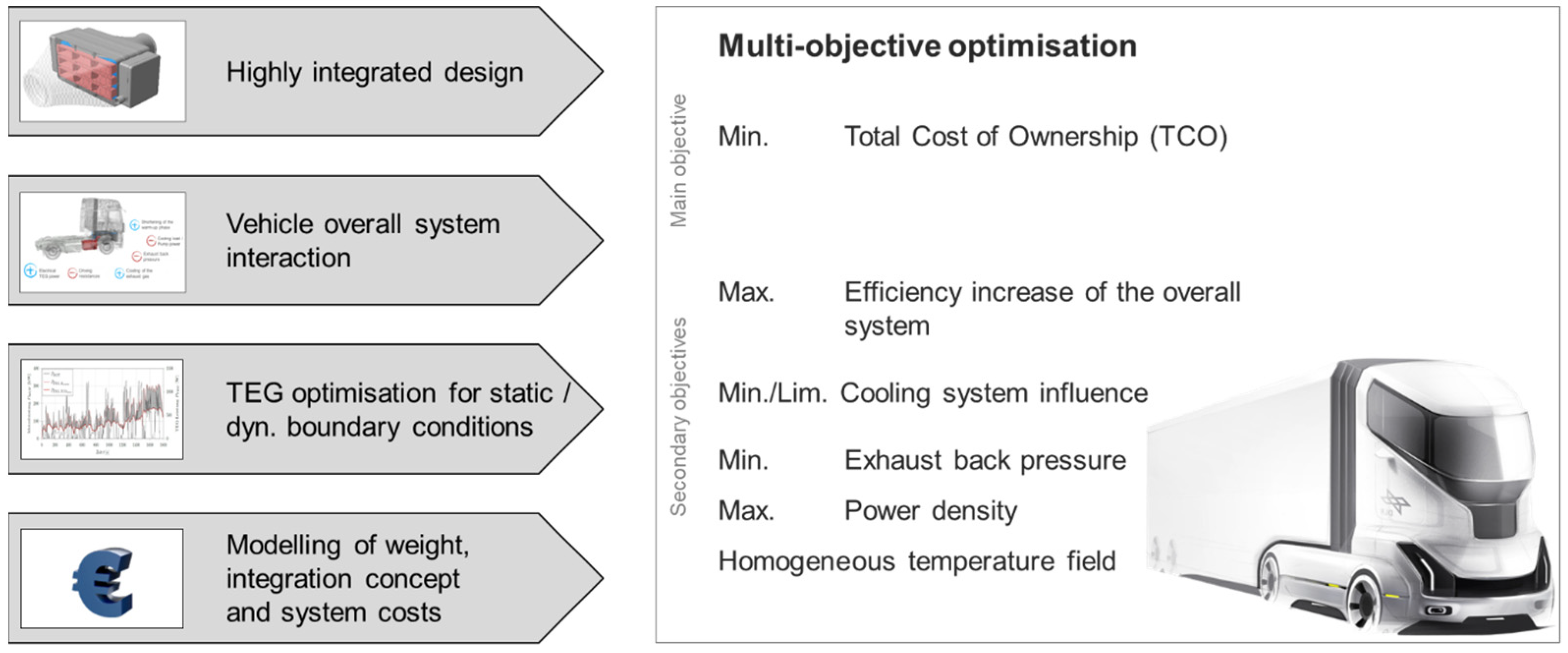
The approaches resulted in large and cost-intensive TEG systems that cannot be applied economically in the HDV. In addition, the interactions of the overall system with the vehicle were only partially or not at all modeled and analyzed. A holistic optimization, i.e., simultaneous technical and economic optimization, under overall system considerations in the vehicle for dynamic driving conditions has not yet been realized. A direct optimization of the cost–benefit ratio for TEG suitable for commercial vehicles was also not possible with the state of the art and is therefore developed in this work. An overview of this holistic method for optimizing TEG systems is shown in
Figure 1.
The method was developed with multi-objective optimization in focus. The main objective is to minimize the Total Cost of Ownership (TCO) of the vehicle including the TEG system, which implies the maximum net fuel reduction while simultaneously minimizing the TEG costs.
The driving scenarios selected are the World Harmonized Vehicle Cycle (WHVC) and the real driving route Stuttgart–Hamburg–Stuttgart (SHHS). While the driving cycle is divided into typical urban, rural and motorway sections without gradients and a length of 1800 s, the real driving route represents a typical two-day long haul HDV operation scenario with all topographies of motorway driving. The total driving time is >70,000 s.
Secondary objectives have been defined in the method to obtain a balanced design that achieves good and high electrical performance both inside and outside the driving cycle. In particular, these secondary objectives focus on optimizing fuel reduction, peak electrical performance, coolant heat input, exhaust backpressure, weight, and long-term stability of the TEG system.
A weighted optimization of the TEG result designs is performed, considering the average and maximum values of the driving cycle and real-world driving results, as well as other characteristic vehicle operating points, such as rated power.
The objective for evaluating the optimization results was defined as reaching the break-even point in the operating time of the WHRS. This implies lower TCO including the TEG system than without and allows determination of an amortization period. Therefore, if the WHRS can be deployed economically under market criteria, it is considered a suitable solution.
2.1. Design of Thermoelectric Generator Systems
The efficiency of the thermoelectric material can be defined by the figure of merit
, where α is the Seebeck coefficient,
is the electrical conductivity,
is the thermal conductivity of the thermoelectric material, and
is the absolute temperature [
14]. For the simulation of TEG designs, thermoelectric module (TEM) material data averaged over the temperature difference
based on experimental measurements are sufficiently accurate.
A TEM can be operated either at maximum efficiency or at maximum power. In applications for automotive waste heat recovery, the lowest cost–benefit ratio can be achieved at maximum power. The efficiency at maximum power
ηmp can be approximated as follows, assuming equal internal and external resistance
according to [
15]:
where
Pel is the output power of the TEM,
is the hot-side heat flow,
Tc and
Th are the temperatures on the cold side and hot side respectively.
Design criteria of the TEG system are decisive for the dimensioning, analysis and evaluation. The energy conversion of the system can be specified with the thermal efficiency
with the electrical power of the TEG
Pel as output and the heat flow from the exhaust gas into the coolant
as input:
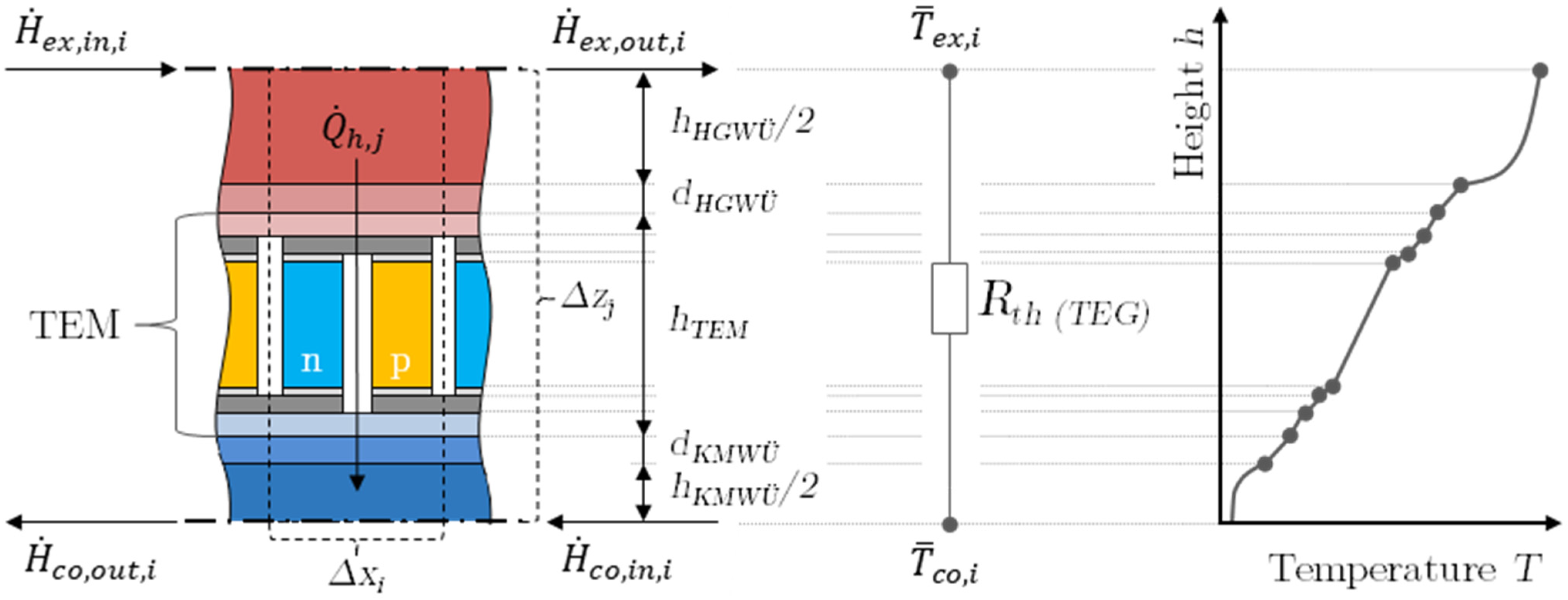
For efficient TEG, simultaneous optimization of the heat exchangers (HEX) and the modules is required.
Figure 2 shows an infinitesimal section of the TEG structure, in particular of the heat exchanger network and the modules. Simplified, the optimization of a TEG represents that of conventional HEX; therefore, the thermal resistances and their design, i.e., the selected geometric dimensions as well as the materials used, are decisive.
A large HEX area (A) and a low area-specific thermal resistance (), or more typically a large heat transfer coefficient (U), usually constitute a good heat exchanger. Both influencing factors lead to higher costs for the HEX design, e.g., better HEX fins have to be used, but can contribute to an optimal cost–benefit ratio of TEG systems. For example, in this work, the share of the thermal resistance of the thermoelectric module in the total resistance of the TEG () is optimized holistically in this work.
2.2. Holistic Thermoelectric Generator System Design
The challenges for economical use in HDV require TEG systems with the highest possible efficiency and low negative impact on the overall vehicle.
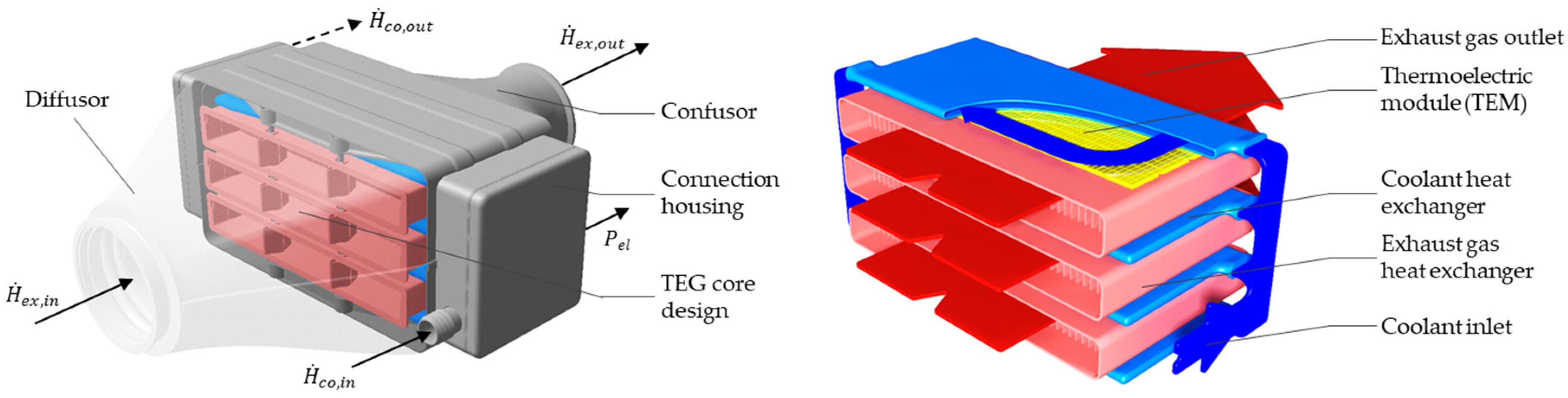
In order to realize a compact design, the TEG system in stacked design, with planar thermoelectric modules (TEM) and heat exchanger in counterflow configuration, has proved to be the most effective.
Figure 3 illustrates this as an example of the TEG-design and objective of minimizing the TCO. In the figure, the TEG-core consists of stacked coolant (COHEX) and hot gas heat exchangers (HGHEX) with intermediate TEM and thermal contacting. The enclosure for test bench investigations around the TEG core is also presented. The highly integrated design used has three separate volumes to protect the modules from oxidation and degradation. High-temperature modules of the material classes bismuth telluride (Bi
2Te
3, cold side) and skutterudite (SKD, hot side) are used for natural gas HDV as optimized solution. The performance characteristics of the selected modules are presented in
Table 2 and the performance maps considered in the simulation are shown in
Figure A1 of the
Appendix A.
A multi-physical 3D finite element method (FEM) with ANSYS version 18.2 and additionally coupled generic models, e.g., for temperature-dependent material data and series cost predictions, are used to simulate and optimize the modules. Selected result variables of the multi-criteria module selection are shown in
Figure 4. In the validated simulation, it is important to achieve a trade-off in the optimization, i.e., with decreasing area-specific thermal resistance (
), the area-specific power (
) increases and the area-specific costs (
) decrease, but at the same time the efficiency (
) decreases.
For simulation and optimization of the TEG system a multiphysical 3D computational fluid dynamics (CFD) simulation using ANSYS Fluent version 18.2 was employed to calculate the conjugate heat transfer, fluid flow and in addition the macroscopic thermoelectric equations (see for details
Figure 5). Thereby, an automated parameter variation was realized for the geometry and mesh creation. The CFD method is precise and promising according to the state of the art (see e.g., [
16,
17]). The optimization objective of this sub model consists in maximizing the heat transfer rate (
) by simultaneously maximum power output (
Pel), efficiency (
) and minimum exhaust and coolant back pressure (Δ
pTEG).
For the time-continuous real drive SHHS, a less accurate simulation environment is used, which can represent the TEG system under real time with Matlab Simulink version V19. For example, heat exchanger correlation and characteristic maps from the CFD simulation are used. The deviation of the two holistic TEG simulation environments is <3% on average. For the claim of holistic design, further sub models are coupled in both simulation environments, which could concern generic sub models regarding TEG costs and weight as well as cover the vehicle overall system interactions in the entire engine map (see
Figure 1). In addition, bypass control was integrated into the simulations, which automatically adjusts the exhaust gas mass flow when the maximum hot-side temperature of the TEM, the maximum exhaust gas backpressure, or the allowable coolant heat input is exceeded.
The main objectives of the multi-criteria TEG simulation environment in this work is the minimum of the total cost of ownership (
TCOmin). In order to be able to evaluate the total cost of ownership over the vehicle’s service life, the net TEG system costs (
) are added to the fixed costs of the reference vehicle and the reduction in fuel consumption (
) by the TEG system is considered in the variable costs. If the TCO of the vehicle with TEG system integration is lower, than the reference vehicle without, the amortization period (
) can be calculated. For the TCO model, an annual mileage of 150,000 km and a service life of 5 years is assumed (for details see [
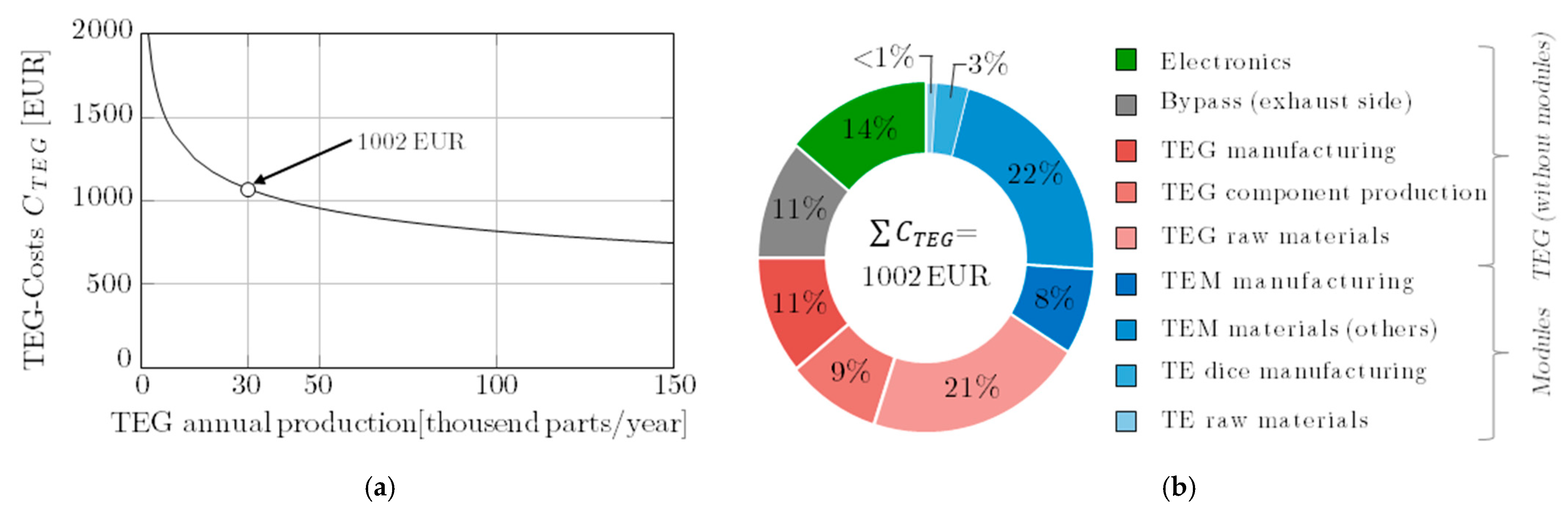
3]). For the TEG cost model (see
Figure 6), series production is assumed and an annual production of 30,000 units. Raw material, material and manufacturing costs are considered, as well as economies of scale using specific learning curves. The model was validated with work of the state of the art (e.g., [
5,
18]).
Further possible main objectives of the multi-criteria TEG simulation environment could be:
Minimum fuel consumption(BSFCmin);
Maximum power output (Pmax);
Maximum power density (PDmax);
Maximum efficiency (ηmax);
Minimal long-term loss of stability or power (LoS/LoP).
2.3. Vehicle Overall System
2.3.1. Vehicle Overall System Interactions
In order to optimize the TEG system from a holistic point of view, all relevant overall system interactions have to be included in the simulation environment and these interactions have to be covered in dynamic driving conditions in the entire operating map. The interactions shown in
Figure 7 are investigated, modeled in the simulation and validated individually. The TEG transfers heat from the exhaust system to the vehicle’s cooling system. As a positive effect, part of the heat is converted by the TEG into electrical energy, which is then used to supply the electrical loads and relieve the load on the power generator or is temporarily stored in the battery. Another positive effect is the reduction of the warm-up phase of the vehicle. The waste heat can be used by a sophisticated integration concept to accelerate the vehicle’s warm-up process up to operating temperature, thus saving fuel and reducing emissions. However, this primarily concerns the currently relevant Emission Test Cycle: World Harmonized Transient Cycle (WHTC).
In the related short-time driving cycle WHVC, taking into account the shortening of the warm-up phase can increase the fuel reduction by another 1.4 percentage points, but this was not considered in this work. On the continuous real driving route, this positive effect is negated.
The main negative effects are the exhaust-side backpressure and the limited coolant capacity. An additional exhaust backpressure of >10 mbar already leads to considerable additional consumption (compare, e.g., [
11]). Our own preliminary work from [
3] for typical long-distance traffic has shown that the cooling system of the natural gas HDV can tolerate an additional cooling power of up to 70–90 kW, depending on the operating point, without the need for additional operation of the vehicle fan.
Several studies such as [
19] and this work concluded that the additional weight requires an additional fuel consumption of 0.15% per 100 kg on average. In contrast to the work of [
12], the additional mechanical load on the coolant pump is almost negligible due to the chosen integration concept.
2.3.2. Vehicle Integration Concept
A secondary objective of this work is to influence the existing vehicle topology as little as possible and thus keep the parasitic effects of the TEG system as low as possible. For example, the additional weight of the TEG system leads to higher driving resistances and thus reduces the efficiency increase achieved by the TEG. A compact TEG design reduces the required installation space to a minimum, which is an important issue in the HDV development.
The most efficient use of TEG technology is its integration into the exhaust tract as a heat source and into the vehicle coolant as a heat sink. Exhaust gas temperatures are highest directly at the output of the combustion engine and generally decrease along the exhaust pipe. Two coolant circuits, the low-temperature coolant circuit (~60 °C) and the high-temperature coolant circuit (~90 °C), are possible as integration positions in the cooling system. The simulations are performed with typical vehicle coolant, i.e., a mixture of tap-water, an anti-freezing compound (glycol/ethanol) mixed with various additives and a mixing ratio of 50:50.
To achieve the objectives of this work, highest efficiency and low influence on the vehicle topology, the TEG integration is chosen on the exhaust gas side at the outlet of the three-way catalyst in the exhaust gas aftertreatment system (ATS) and on the coolant side the integration into the low-temperature coolant circuit is selected.
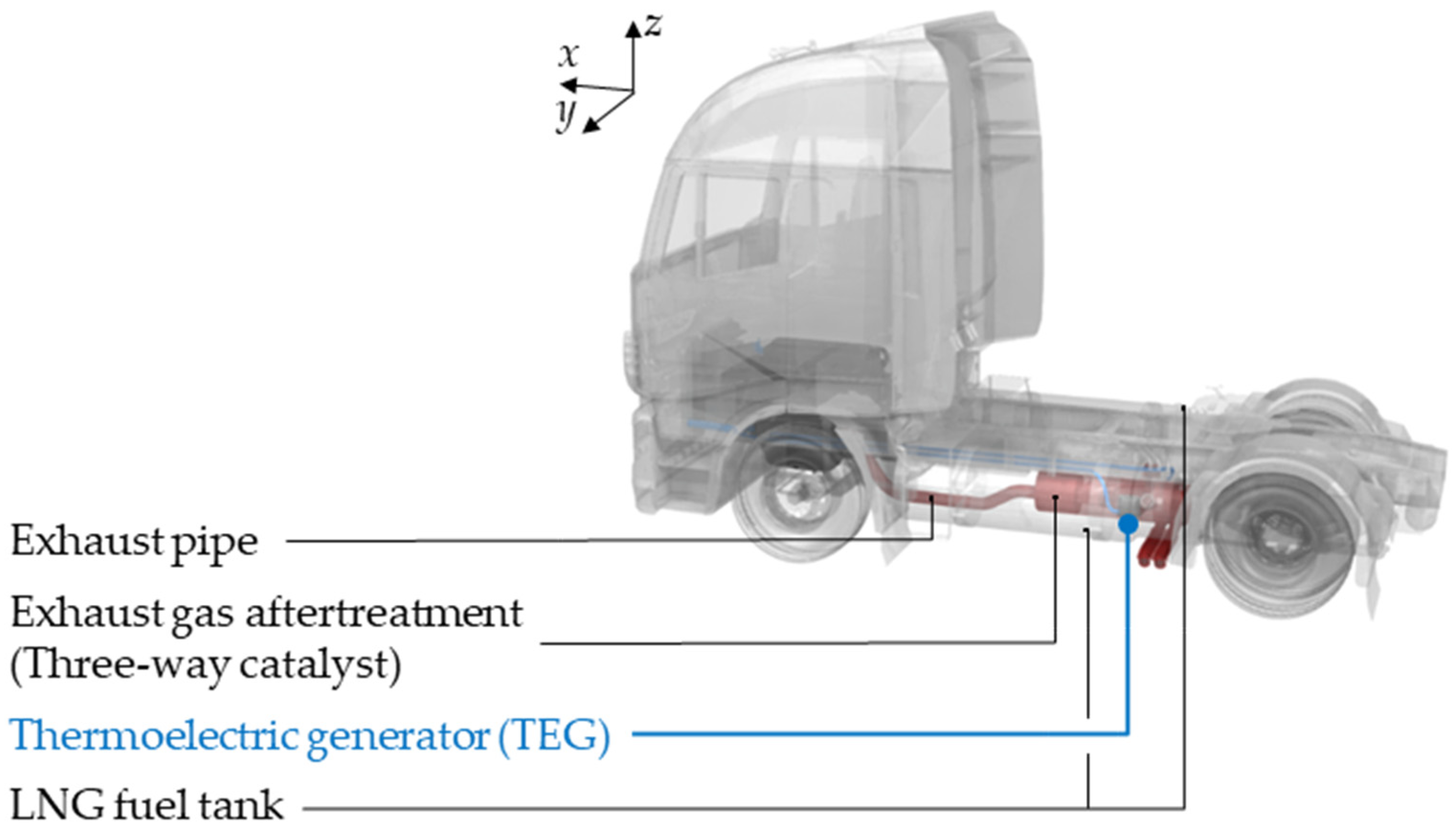
Figure 8 illustrates the integration concept. Due to the compact design and high-power density achieved, the TEG including bypass and bypass flap could be positioned in the exhaust gas aftertreatment system for the first time without major redesign. For example, no volume is lost for fuel tanks.
3. Results
3.1. Reference Vehicle and Boundary Conditions
A reference vehicle was selected to demonstrate the application of the holistic design method. The Iveco Stralis NP460 represents a HDV of the current state of the art vehicle technology with stoichiometric combustion process and conventional electrical on-board network topology, suitable for long-haul applications. The main characteristics of the reference vehicle is shown in
Table 3.
In order to obtain representative and realistic results, an extensive potential analysis of the relevant and available enthalpy flows in the vehicle is required (see details in [
3]). An overview of the characteristic operating points as well as the mean (mean) and maximum (max) values in the WHVC driving cycle and the SHHS real driving route as well as the distribution of exhaust enthalpy is shown in
Figure 9.
The defined operating points (OP) of the driving cycles are given in
Table 4 as empty driving (15 t total weight) and under full load (40 t total weight). In addition to the determined temperature of the exhaust gas
and coolant
of the position for TEG integration, the respective mass
or volume flows
as well as the available exhaust gas enthalpy
with reference to the ambient temperature (
20 °C) are indicated.
3.2. Holistic Thermoelectric System Optimization
Based on the simulation environments and the use of an evolutionary algorithm, geometrically free parameter variation was performed.
Figure 10 shows the resulting Pareto fronts for example operating points for the cost–benefit ratio and electrical power. Each point in the plots represents a geometrically different TEG design. For each operating point, the algorithm used calculated more than 10,000 designs. With the help of these Pareto fronts, a holistic optimum for the respective TEG variant can be determined on the basis of the aforementioned weightings.
Detailed results of the TEG variants for minimizing TCO (
TCOmin) and minimizing fuel consumption (
BSFCmin) are shown in
Table 5. Unit costs of 1002 EUR, an additional vehicle weight of 27.4 kg, a HGHEX of 1420 cm
2, and segmented high-temperature TEM are determined for the
TCOmin variant. For the
BSFCmin variant, the unit cost increases only slightly to 1053 EUR, as well as the weight to 28.3 kg and the HGHEX area to 1655 cm
2, since the vehicle interactions, in particular the limitation caused by the maximum permissible heat input into the coolant, do not allow any further increase. Therefore, the bypass section must be used to an increasing extent. In addition to detailed information for the three sections of the WHVC, typical light, medium, and heavy sections of the SHHS route are also provided. Based on the average (
) and the maximum TEG power (
) in the respective driving scenario, the resulting net fuel reduction (Δ
BSFC) is determined as the outcome variable. The TEG power represents the electrical power (
) multiplied by the efficiency (~90%) of the power electronics and the maximum power point tracker. This corresponds to a kilometer-related emission reduction (Δ
CO2). Based on the fuel reduction and the underlying TCO base model, the amortization period of the system can be calculated and varies between 0.7–1.9 years.
With the considered conventional on-board network topology of the vehicle, an average consumer power of 1025 W according to [
21] is assumed. The tabular results show that the average TEG power mostly offers an even higher level and thus the alternator of the vehicle can be completely replaced—which, however, was not realized in this work. The surplus electrical power of the TEG system is stored in the battery. For the BSFC
min TEG design, a further increase in efficiency of over 25% would be possible on the SHHS real driving route, if the electrification of the auxiliary units would allow this.
The dynamic results of the engine power (
) and TEG powers of the design variants are shown over time of the WHVC in
Figure 11. The high dynamics of both result variables and the increasing power values over time due to the increasing load requirements of the driving profile are remarkable.
In the
Appendix A in
Figure A2, a scatter diagram with the respective density distributions shows the result variables of both result designs for the real driving route SHHS
40 t. In the diagram, an accumulation of points can be seen at a TEG power of about 200 W with varying engine powers. This reveals the relatively large time share of bypass operation (9% for the TEG variant
TCOmin and 14% for the TEG variant
BSFCmin), especially due to the limited cooling system capacity of the vehicle. In
Table 6 the obtained results of the simulation study are presented.
3.3. Validation by a Functional Model
To validate the simulation environment, the TEG design with objective
TCOmin was selected with a slight modification for the 1:1 scale hardware realization. The experiment was carried out on the institute’s own hot gas generator including vehicle replication of the vehicle cooling system by temperature control units and multiple maximum powerpoint trackers, as shown in
Figure 12. The selected result design represents the weighted minimum cost–benefit ratio, as shown in
Figure 10, and has a rated power of about 3000 W. TEG result designs with a rated power greater than 6000 W were also available for selection as simulation results.
As a result, an electrical power of up to 2697 W could be measured at the operating point SHHS
40 t,max (deviation to OP of
Table 4 due to max. hot gas generator power of 200 kW, therefore
= 0.25 kg/s,
= 20 °C,
= 0.5 dm
3/s). This corresponds to a deviation from the simulation of <4%. Further detailed results regarding the module surface temperature in the longitudinal direction to the exhaust gas flow in the TEG, electrical power and exhaust gas back pressure are included in
Figure 13. The good agreement between simulation and experiment is evident and the deviation for all result variables is less than 6% on average.
The experimental power density is 174 W/kg (simulative: 189 W/kg) and 327 W/dm3 (simulative: 354 W/dm3), respectively.
4. Discussion
For the first time, the possibility of an economical use of a thermoelectric generator system in the amortization period of less than 2 years for a natural gas HDV is shown. The fuel reduction in the conventional vehicle topology is already up to 2.8%. The fuel reduction is 930% higher than the best state of the art specification of [
13] for natural gas HDV.
As a state-of-the-art assessment,
Figure 14 presents the power densities of TEG concepts according to the state of the art and in the context of this work over the years. For a consistent basis of comparison, electrical power taken to determine power densities together with the weight and volume of the TEG core. The TEG core includes the components without the power electronics. To date, the state of the art has known results for diesel HDV application areas only. The gravimetric and volumetric power density could be increased up to 298 W/kg and 568 W/dm
3 with the result of this work.
The power densities of the functional model specified and measured in
Section 3.3 already increase the previous best state of the art of [
9] by 237% and 547%, respectively. Considering the objective
TCOmin, 144 modules and only 0.8 kg of thermoelectric material are used. This corresponds to a material reduction of about 88% compared to the aforementioned work of the state of the art. As can be seen from the cost distribution in
Figure 6, the thermoelectric raw material represents a negligible cost share of <1% in the TEG design as a result of this work. In addition, a maximum thermal efficiency (
) of up to 3.3% was measured, which represents an increase of 157% over the previous best value of the state of the art of [
24].
The state of the art for thermoelectric generator systems in HDV has been expanded and improved in several aspects. The increase in the level of technological maturity brings this technology closer to series application.
5. Conclusions
A methodology for holistic optimization of thermoelectric generator systems for heavy-duty vehicles was presented, ranging from highly integrated generator design to overall vehicle integration and interactions, and multi-objective optimization. Exemplary results were presented for the natural gas heavy-duty vehicle. The achieved reduction of fuel consumption is 1.8–2.8% and thus the reduction of emissions is 15.7–34.9 gCO2/km. For the first time, the variant for minimizing the total cost of ownership enables an economically interesting amortization period of significantly less than 2 years (minimum: 0.7 years). In addition, the vehicle integration concept was presented, and the simulation study was successfully validated using an experimental functional model.
The largest benefit was achieved in terms of cost–benefit ratio for the natural gas heavy-duty vehicle application with 344 EUR/% or 32 EUR/(gCO2 km). Finally, a state-of-the-art evaluation was presented showing the significant improvement based on gravimetric power density of up to 298 W/kg and volumetric power density of up to 568 W/dm3 for heavy vehicle applications.
A commercially attractive TEG system was presented that can already contribute to the cost-effective reduction of greenhouse gas emissions from heavy-duty vehicles.
Author Contributions
Conceptualization, L.H.; methodology, L.H.; software, L.H. and T.K.; validation, L.H., J.S., T.K. and L.H.; formal analysis, L.H.; investigation, L.H.; resources, L.H.; data curation, L.H. and T.K.; writing—original draft preparation, L.H.; writing—review and editing, L.H., J.S. and T.K.; visualization, L.H.; supervision, L.H.; project administration, L.H.; funding acquisition, L.H. All authors have read and agreed to the published version of the manuscript.
Funding
This research was funded by the Ministry of Economic Affairs. Labour and Housing of Baden-Württemberg within the project “HD-TEG” (grant number: 3-4332.62-DLR-IFF/12) and the DLR Technology Marketing. The authors explicitly acknowledge this support and appreciate the cooperation with all partners for their contributions to this work.
Institutional Review Board Statement
Not applicable.
Informed Consent Statement
Informed consent was obtained from all subjects involved in the study.
Data Availability Statement
The data presented in this study was measured experimentally or calculated analytical and numerically by the authors. Further details about the results may be requested to the authors.
Conflicts of Interest
The authors declare no conflict of interest.
Appendix A
Figure A1.
Performance diagram of the considered segmented high temperature module of the manufacturer LG Chem, from [
3].
Figure A1.
Performance diagram of the considered segmented high temperature module of the manufacturer LG Chem, from [
3].
Figure A2.
Results of dynamic TEG optimization with different objectives on the SHHS route.
Figure A2.
Results of dynamic TEG optimization with different objectives on the SHHS route.
References
- European Commission 2018/0143(COD) 284 Final: Proposal for a Regulation of the European Parliament and of the Council Setting CO2 Emission Performance Standards for New Heavy-Duty Vehicles. 2018. Available online: https://eur-lex.europa.eu/legal-content/EN/TXT/?uri=COM%3A2018%3A284%3AFIN (accessed on 4 November 2021).
- Bünger, U.; Landinger, H.; Weindorf, W.; Rheinhold, W.; Zerhusen, J.; Zittel, W. Vergleich von CNG und LNG zum Einsatz in Lkw im Fernverkehr; Final Report; Ludwig-Bölkow-Systemtechnik GmbH: Munich, Germany, 2016. [Google Scholar]
- Heber, L.; Schwab, J.; Kangyi, Y.; Grill, M.; Rinderknecht, F.; Friedrich, H.E. HD-TEG: Effizienzsteigerungspotential bei Nutzfahrzeugen Durch den Einsatz Eines Neuartigen Abwärmenutzungssystems (Thermoelektrik); Project Report; DLR: Stuttgart, Germany, 2021. [Google Scholar]
- Heber, L.; Schwab, J. Modelling of a thermoelectric generator for heavy-duty natural gas vehicles: Techno-economic approach and experimental investigation. Appl. Therm. Eng. 2020, 174, 115156. [Google Scholar] [CrossRef]
- Kober, M. Holistic development of thermoelectric generators for automotive applications. J. Electron. Mater. 2020, 49, 2910–2919. [Google Scholar] [CrossRef] [Green Version]
- Liu, W.; Wang, D.; Liu, Q.; Zhou, W.; Shao, Z.; Chen, Z.-G. High-performance GeTe-based Thermoelectrics: From materials to devices. Adv. Energy Mater. 2020, 10, 2000367. [Google Scholar] [CrossRef]
- Tan, G.; Zhao, L.-D.; Kanatzidis, M.G. Rationally designing high-performance bulk thermoelectric materials. Chem. Rev. 2016, 116, 12123–12149. [Google Scholar] [CrossRef] [PubMed]
- Bernath, M.G. Ganzheitliche Modellerstellung zur Wirkungsgraderhöhung von Nutzfahrzeugen Durch Thermische Rekuperation; Technische Universität München: Munich, Germany, 2015. [Google Scholar]
- Bass, J.C.; Elsner, N.B.; Leavitt, F.A. Performance of the 1 kW thermoelectric generator for diesel engines. In Proceedings of the 13th International Conference on Thermoelectric, Kansas City, MO, USA, 30 August–1 September 1994; pp. 295–298. [Google Scholar] [CrossRef]
- Eglseer, A.; Hager, J.; Höfer, C. Einsatzmöglichkeiten und Wirtschaftlichkeit von Thermoelektrischen Generatoren im Nutzfahrzeug. In Thermische Rekuperation im Kraftfahrzeug; Neugebauer, S., Ed.; Expert Verlag: Munich, Germany, 2009. [Google Scholar]
- Gaiser, G.; Frobenius, F. Potentiale und Grenzen von Thermoelektrischen Generatoren bei der Integration in Abgasanalagen von Kraftfahrzeugen. In 2. VDI Fachkonferenz Thermische Rekuperation in Fahrzeugen; Institut für Kolbenmaschinen (IFKM): Stuttgart, Germany, 2015. [Google Scholar]
- Risseh, A.E.; Nee, H.-P.; Erlandsson, O.; Brinkfeldt, K.; Contet, A.; Lng, F.F.; Gaiser, G.; Saramat, A.; Skare, T.; Nee, S.; et al. Design of a thermoelectric generator for waste heat recovery application on a drivable heavy duty vehicle. SAE Int. J. Commer. Veh. 2017, 10, 26–44. [Google Scholar] [CrossRef] [Green Version]
- Hervas-Blasco, E.; Navarro-Peris, E.; De Rosa, M.; Corberán, J.M. Potential fuel saving in a powertrain derived from the recovery of the main energy losses for a long haul European mission. Energy Convers. Manag. 2017, 150, 485–499. [Google Scholar] [CrossRef] [Green Version]
- Rowe, D.M. Handbook of Thermoelectrics; CRC: Boca Raton, FL, USA, 1995; ISBN 0849301467. [Google Scholar]
- Lee, H.S. Thermal Design: Heat Sinks, Thermoelectrics, Heat Pipes, Compact Heat Exchangers, and Solar Cells; Wiley: Hoboken, NJ, USA, 2010. [Google Scholar] [CrossRef]
- Bai, S.; Lu, H.; Wu, T.; Yin, X.; Shi, X.; Chen, L. Numerical and experimental analysis for exhaust heat exchangers in automobile thermoelectric generators. Case Stud. Therm. Eng. 2014, 4, 99–112. [Google Scholar] [CrossRef] [Green Version]
- Favarel, C.; Bédécarrats, J.-P.; Kousksou, T.; Champier, D. Experimental analysis with numerical comparison for different thermoelectric generators configurations. Energy Convers. Manag. 2016, 107, 114–122. [Google Scholar] [CrossRef]
- LeBlanc, S.; Yee, S.K.; Scullin, M.L.; Dames, C.; Goodson, K.E. Material and manufacturing cost considerations for thermoelectrics. Renew. Sustain. Energy Rev. 2014, 32, 313–327. [Google Scholar] [CrossRef]
- Grelet, V.; Tipner, P. Assessment of evaporators used in waste heat recovery rankine cycle based systems for heavy duty truck application. In Energy and Thermal Management, Air Conditioning, Waste Heat Recovery; Junior, C., Jänsch, D., Dingel, O., Eds.; Springer International Publishing: Cham, Switzerland, 2017; pp. 41–52. [Google Scholar] [CrossRef]
- Lastauto Omnibus. Vergleichstest; Lastauto Omnibus: Stuttgart, Germany, 2017; Volume 1-2/2017, p. 19. [Google Scholar]
- Dünnebeil, F.; Reinhard, C.; Lambrecht, U.; Kies, A.; Hausberger, S.; Rexeis, M. Zukünftige Maßnahmen zur Kraftstoffeinsparung und Treibhausgasminderung bei Schweren Nutzfahrzeugen. Final Report. Environmental Research Plan of the Federal Ministry for the Environment, Nature Conservation, Building and Nuclear Safety; Institut für Verbrennungskraftmaschinen und Thermodynamik: Heidelberg, Germany, 2015; Volume 2058, Available online: https://www.umweltbundesamt.de/sites/default/files/medien/378/publikationen/texte_32_2915_kurz_kraftstoffeinsparung_bei_nutzfahrzeugen.pdf (accessed on 4 November 2021).
- Steiner, B.; Follmer, M. Application of Thermoelectric Generators for Commercial Vehicles; Automotive Thermoelectricity: Wiesbaden, Germany, 2013. [Google Scholar]
- Cleary, M.; Zhang, Y.; Mazzotta, A.; Young, H.; Meda, L.; Wang, X.; Joshi, G.; Yang, J.; Engber, M.; Ma, Y. Development of thermoelectric generators for multiple vehicle exhaust waste heat recovery applications. In Proceedings of the 4th Thermoelectrics Conference Utilizing Waste Heat, Berlin, Germany, 10–12 December 2014. [Google Scholar]
- Zhang, Y.; Cleary, M.; Wang, X.; Kempf, N.; Schoensee, L.; Yang, J.; Joshi, G.; Meda, L. High-temperature and high-power-density nanostructured thermoelectric generator for automotive waste heat recovery. Energy Convers. Manag. 2015, 105, 946–950. [Google Scholar] [CrossRef] [Green Version]
Figure 1.
Development approach for TEG systems based on multi-objective optimization and consideration of the overall vehicle interaction as well as holistic design criteria.
Figure 1.
Development approach for TEG systems based on multi-objective optimization and consideration of the overall vehicle interaction as well as holistic design criteria.
Figure 2.
Thermodynamic design aspects of thermoelectric generators.
Figure 2.
Thermodynamic design aspects of thermoelectric generators.
Figure 3.
Principle illustration of the highly integrated TEG stack architecture (counter flow heat exchanger design) with objective TCOmin for the natural gas HDV.
Figure 3.
Principle illustration of the highly integrated TEG stack architecture (counter flow heat exchanger design) with objective TCOmin for the natural gas HDV.
Figure 4.
Multi-criteria design and optimization of segmented high temperature modules. (a) Area-specific power density and efficiency. (b) Area-specific costs.
Figure 4.
Multi-criteria design and optimization of segmented high temperature modules. (a) Area-specific power density and efficiency. (b) Area-specific costs.
Figure 5.
Simplified CFD simulation model of the TEG. (a) Schematic thermal system model. (b) CFD-meshing and boundary conditions.
Figure 5.
Simplified CFD simulation model of the TEG. (a) Schematic thermal system model. (b) CFD-meshing and boundary conditions.
Figure 6.
TEG cost model. (a) TEG costs by economics of scale. (b) Cost breakdown of the TEG design TCOmin.
Figure 6.
TEG cost model. (a) TEG costs by economics of scale. (b) Cost breakdown of the TEG design TCOmin.
Figure 7.
Interactions between the TEG system and the relevant vehicle subsystems.
Figure 7.
Interactions between the TEG system and the relevant vehicle subsystems.
Figure 8.
Vehicle integration of the TEG system in a tractor unit of a natural gas HDV.
Figure 8.
Vehicle integration of the TEG system in a tractor unit of a natural gas HDV.
Figure 9.
Overview of results of the potential analysis of the natural gas HDV. (a) Engine torque over speed. (b) Exhaust gas enthalpy analysis.
Figure 9.
Overview of results of the potential analysis of the natural gas HDV. (a) Engine torque over speed. (b) Exhaust gas enthalpy analysis.
Figure 10.
Overview of the multi-objective optimization of the TEG result designs with free geometric variation. (a) Cost–benefit optimization. (b) Electrical power optimization.
Figure 10.
Overview of the multi-objective optimization of the TEG result designs with free geometric variation. (a) Cost–benefit optimization. (b) Electrical power optimization.
Figure 11.
Results of dynamic TEG optimization with different objectives in WHVC driving cycle. (a) Empty (15 t gross weight). (b) Loaded (40 t gross weight).
Figure 11.
Results of dynamic TEG optimization with different objectives in WHVC driving cycle. (a) Empty (15 t gross weight). (b) Loaded (40 t gross weight).
Figure 12.
Development process up to test bench investigation of TEG design TCOmin.
Figure 12.
Development process up to test bench investigation of TEG design TCOmin.
Figure 13.
Results of the experimental investigation of the TEG functional model. (a) Module surface temperature. (b) Electrical output power map. (c) Exhaust gas back pressure at different operating points.
Figure 13.
Results of the experimental investigation of the TEG functional model. (a) Module surface temperature. (b) Electrical output power map. (c) Exhaust gas back pressure at different operating points.
Figure 14.
Comparison of gravimetric (left) and volumetric (right) power density of TEG systems for HDV applications (data from: 1: [
8] 2: [
22], 3: [
23,
24], 4: [
10], 5: [
12]).
Figure 14.
Comparison of gravimetric (left) and volumetric (right) power density of TEG systems for HDV applications (data from: 1: [
8] 2: [
22], 3: [
23,
24], 4: [
10], 5: [
12]).
Table 1.
State of the art for TEG systems in commercial vehicles reported in the literature (chronologically ordered); data based on [
4].
Table 1.
State of the art for TEG systems in commercial vehicles reported in the literature (chronologically ordered); data based on [
4].
| HDV | TEG System (Institution/Project Name) | Stage of Development | Thermoelectric Material | Max. Power | Power Density | Efficiency | Fuel Saving | Costs | Ref |
|---|
| | | | | Pel,max | ψTEG | ηmax | ΔBSFC | cTEG,net | |
| | | | | (WSim./WExp.) | (W kg−1/W L−1) | (%) | (%) | (USD W−1) | |
| Diesel | Hi-Z Technology | up to vehicle installation | Bi2Te3 | -/1068 1 | 73.5/97.1 | N/A | N/A | N/A | [8] |
| Diesel | Magna Powertrain Eng. | sim. and exp. study | Bi2Te3 and SiGe | 2730 1/200 | N/A. | 5.6−9.5 1 | 0.3−0.56 1 | N/A | [9] |
| Diesel | Eberspächer | sim. and exp. study | Bi2Te3 | 1060 3/550 3 | N/A. | 1.6 3 | N/A | N/A | [10] |
| Diesel | Bernath | simulation study | Bi2Te3 and SKD | 1200 2/500 2 | N/A. | N/A | 0.4 2 | N/A | [11] |
| Diesel | Scania et al. | sim. and exp. study | Bi2Te3 and TAGS | 785 2+3/776 2+3 | N/A. | 1.9 3−5.4 2 | N/A | 150 | [12] |
| NG | GASTone | sim. study | SKD | 820 3/245 3 | N/A. | N/A | 0.3 3 | N/A | [13] |
Table 2.
Thermoelectric module characteristics related to this work of the manufacturer LG Chem.
Table 2.
Thermoelectric module characteristics related to this work of the manufacturer LG Chem.
| Vehicle | Exhaust Temperatures | TEM Material | | | Image | Reference |
|---|
| | (°C) | (-) | (%) | (W/cm2) | (-) | [-] |
|---|
| Natural gas HDV | 500–800 | segmented Bi2Te3 & SKD | 9 | 3 | ![Energies 15 00015 i001]() | [3,4] |
Table 3.
Main characteristics of the reference vehicle (natural gas HDV; *: calculation).
Table 3.
Main characteristics of the reference vehicle (natural gas HDV; *: calculation).
| Specification | Unit | Iveco Stralis NP460 |
|---|
| Vehicle type | (-) | Conventional |
| Battery capacity | (Ah/kWh) | 225/5.4 |
| ICE | (-) | stoichiometric gasoline engine principle |
| Type of engine | (-) | In-line 6-cylinder |
| Displacement | (dm3) | 12.9 |
| Max. performance | (kW) | 338 (at 1900 min−1) |
| Weight of vehicle | (t) | 7.6 |
| Exhaust emission standard | (-) | EURO VI C |
| Year of production | (-) | 2017 |
| Fuel consumption | (kg/100 km) | 32.2 (see [20]) |
| CO2-emissions * | (g/km) | 818 |
Table 4.
Overview of the defined operating points (OP) and vehicle boundary conditions of the natural gas HDV.
Table 4.
Overview of the defined operating points (OP) and vehicle boundary conditions of the natural gas HDV.
| OP | | | | | | |
|---|
| WHVC15 t,mean | 25 | 609 | 0.06 | 33.4 | 50 | 0.3 |
| WHVC15 t,max | 46.1 | 659 | 0.16 | 96.2 | 43 | 0.4 |
| WHVC40 t,mean | 42.7 | 652 | 0.1 | 64.5 | 52 | 0.3 |
| WHVC40 t,max | 55.6 | 710 | 0.22 | 169.4 | 46 | 0.4 |
| SHHS40 t,mean | 35.5 | 676 | 0.14 | 94.5 | 54 | 0.4 |
| SHHS 40 t,max | 88.9 | 743 | 0.36 | 275.3 | 58 | 0.6 |
Table 5.
Overview of the results achieved by using TEG in HDV ( = 20 °C) with the objectives TCOmin and BSFCmin (integration: after ATS and low-temperature coolant circuit).
Table 5.
Overview of the results achieved by using TEG in HDV ( = 20 °C) with the objectives TCOmin and BSFCmin (integration: after ATS and low-temperature coolant circuit).
| Vehicle (TEG-Design) | Reference Cycle/Route | Overall Vehicle | TCO-Balance | TEG-System |
|---|
| | | | | | |
|---|
| Natural gas (TCOmin) | WHVC15t Overall | 2.5 | 15.7 | 1002 | 1.8 | 1954 | 1030 | 27.4 |
| WHVC40t Overall | 2.3 | 24.6 | 1 | 2371 | 1424 |
| WHVC40t Rural | 2.3 | 34.1 | 0.7 | 1959 | 1100 |
| WHVC40t Urban | 1.9 | 22.4 | 1.1 | 2252 | 1518 |
| WHVC40t Motorway | 2.4 | 19.2 | 1.3 | 2371 | 2009 |
| SHHS40t Overall | 2.1 | 18.9 | 1.4 | 2688 | 1686 |
| SHHS40t Light | 2.5 | 15.9 | 1.8 | 2610 | 1741 |
| SHHS40t Medium | 2 | 19.8 | 1.3 | 2614 | 1850 |
| SHHS40t Heavy | 2.1 | 27.3 | 0.9 | 2688 | 1897 |
| Natural gas (BSFCmin) | WHVC15t Overall | 2.6 | 16.4 | 1053 | 1.9 | 2170 | 1085 | 28.3 |
| WHVC40t Overall | 2.4 | 25.6 | 1.1 | 2691 | 1506 |
| WHVC40t Rural | 2.4 | 34.9 | 0.8 | 2099 | 1127 |
| WHVC40t Urban | 2 | 23 | 1.2 | 2560 | 1585 |
| WHVC40t Motorway | 2.6 | 21.5 | 1.4 | 2691 | 2227 |
| SHHS40t Overall | 2.1 | 19 | 1.5 | 3150 | 1647 |
| SHHS40t Light | 2.8 | 17.4 | 1.9 | 2899 | 1367 |
| SHHS40t Medium | 2.1 | 20.3 | 1.3 | 2920 | 1685 |
| SHHS40t Heavy | 1.8 | 22.5 | 1.2 | 3150 | 1881 |
Table 6.
Overall results of the TEG-simulation environment for the natural gas HDV.
Table 6.
Overall results of the TEG-simulation environment for the natural gas HDV.
| Efficiency Improvement (ΔBSFC) (|%|) | Min. Cost–Benefit Ratio | Max. Power Density | Min. Amortization Period (Year) |
|---|
| (EUR/%) | (EUR/(gCO2 km)) | (W/kg) | (W/dm3) |
|---|
| 1.8–2.8 | 344 | 32 | 298 | 568 | 0.7 |
| Publisher’s Note: MDPI stays neutral with regard to jurisdictional claims in published maps and institutional affiliations. |
© 2021 by the authors. Licensee MDPI, Basel, Switzerland. This article is an open access article distributed under the terms and conditions of the Creative Commons Attribution (CC BY) license (https://creativecommons.org/licenses/by/4.0/).


