Article

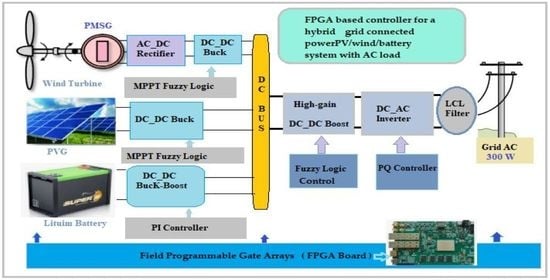
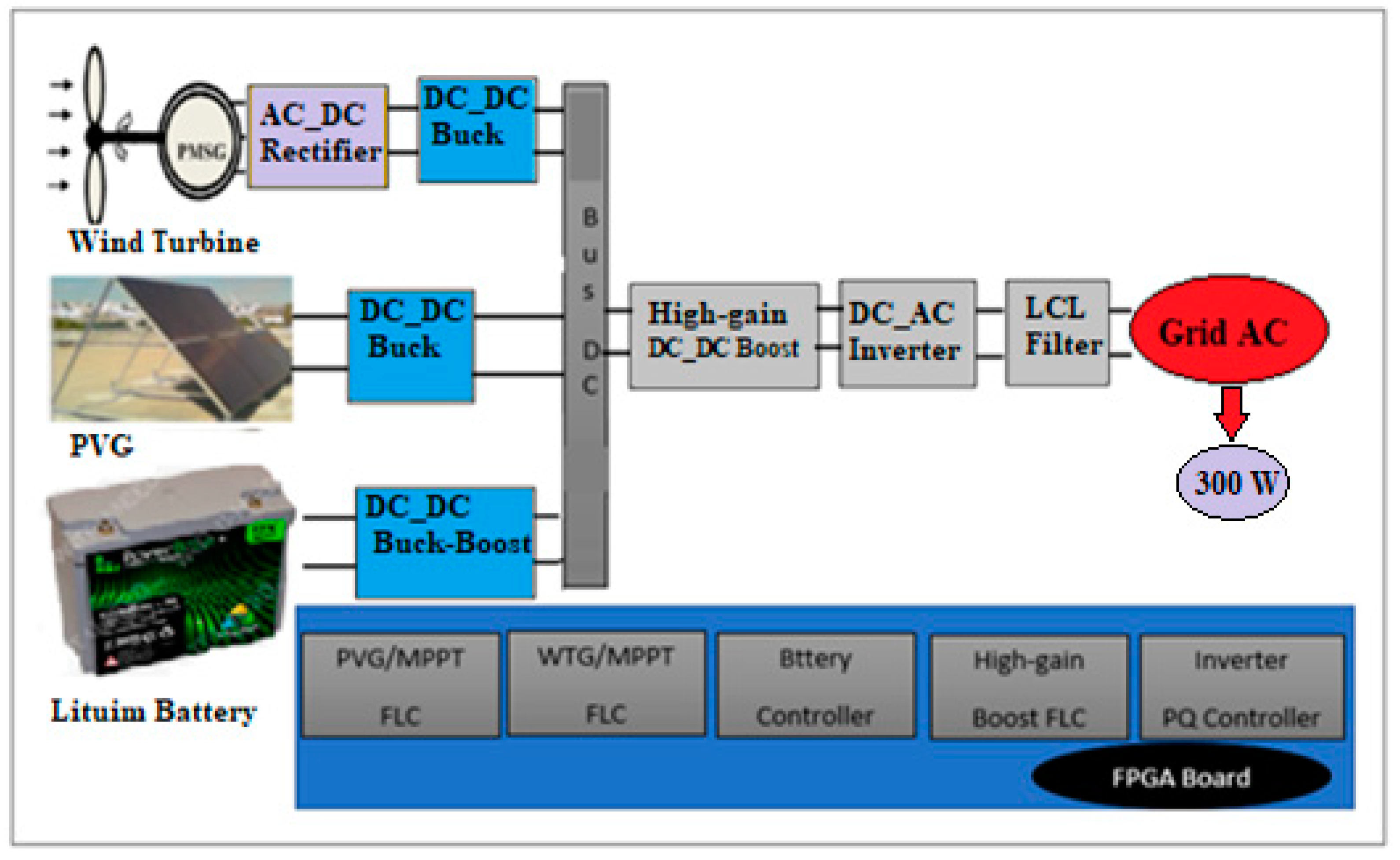
FPGA-Based Controller for a Hybrid Grid-Connected PV/Wind/Battery Power System with AC Load

1
UR-LAPER, Faculty of Sciences of Tunis, University of Tunis El Manar Tunis, Tunis 1068, Tunisia
2
Department of Electrical and Information Engineering, Polytechnic University of Bari, st. E. Orabona 4, I-70125 Bari, Italy
*
Author to whom correspondence should be addressed.
Energies 2021, 14(8), 2108; https://doi.org/10.3390/en14082108
Submission received: 22 February 2021 / Revised: 2 April 2021 / Accepted: 7 April 2021 / Published: 9 April 2021
(This article belongs to the Special Issue Assessment of Photovoltaic-Battery Systems)

Abstract

:
The development and optimization of a hybrid system composed of photovoltaic panels, wind turbines, converters, and batteries connected to the grid, is first presented. To generate the maximum power, two maximum power point tracker controllers based on fuzzy logic are required and a battery controller is used for the regulation of the DC voltage. When the power source varies, a high-voltage supply is incorporated (high gain DC-DC converter controlled by fuzzy logic) to boost the 24 V provided by the DC bus to the inverter voltage of about 400 V and to reduce energy losses to maximize the system performance. The inverter and the LCL filter allow for the integration of this hybrid system with AC loads and the grid. Moreover, a hardware solution for the field programmable gate arrays-based implementation of the controllers is proposed. The combination of these controllers was synthesized using the Integrated Synthesis Environment Design Suite software (Version: 14.7, City: Tunis, Country: Tunisia) and was successfully implemented on Field Programmable Gate Arrays Spartan 3E. The innovative design provides a suitable architecture based on power converters and control strategies that are dedicated to the proposed hybrid system to ensure system reliability. This implementation can provide a high level of flexibility that can facilitate the upgrade of a control system by simply updating or modifying the proposed algorithm running on the field programmable gate arrays board. The simulation results, using Matlab/Simulink (Version: 2016b, City: Tunis, Country: Tunisia, verify the efficiency of the proposed solution when the environmental conditions change. This study focused on the development and optimization of an electrical system control strategy to manage the produced energy and to coordinate the performance of the hybrid energy system. The paper proposes a combined photovoltaic and wind energy system, supported by a battery acting as an energy storage system. In addition, a bi-directional converter charges/discharges the battery, while a high-voltage gain converter connects them to the DC bus. The use of a battery is useful to compensate for the mismatch between the power demanded by the load and the power generated by the hybrid energy systems. The proposed field programmable gate arrays (FPGA)-based controllers ensure a fast time response by making control executable in real time.

Graphical Abstract

1. Introduction

Today, a significant amount of the energy is produced by fossil sources, which generate greenhouse gas emissions and pollution. Renewable energy sources (RES) are essential to reduce this dependence. This study focused on distributed RES. A hybrid energy system constituted by wind turbine generators (WTG), photovoltaic generators (PVG), and batteries has been applied for grid-connected operation [1] and in various autonomous applications [2]. An autonomous system based on photovoltaic and wind energy with a PI regulator is described in [3]. Energy efficiency and sizing of wind/photovoltaic hybrid systems for electrification of marine oil well heads are being studied [4]. As a result, a pilot project allowing a grid-connected high-gain photovoltaic system is proposed in [5]. The design of an inverter for a hybrid power system is discussed in [6]. A hybrid system coupled to the grid and a new inverter topology was designed in [7]. Power converters and control units are essential for energy and its management, as well as for the maximum power supplied by PVG and WTG. For this reason, there are different approaches to pursuing maximum power points (MPPs) in the relevant published literature, such as incremental conductance [8], the parasitic capacity method [9], or the perturbation and observation method [10]. They depend also on the environmental parameters. Nevertheless, the uncertainties related to these conditions have reduced the performance of these techniques, particularly under the effect of variations in solar radiation, wind speed, and temperature. Fuzzy logic is usually used to achieve the maximum power delivered by PVG [8,10,11] and WTG [12,13,14] because it facilitates the application of energy management rules. In addition, it does not require a perfectly known mathematical model. Moreover, fuzzy logic’s robustness and adaptability in the presence of parameter changes or unbalances in the system are well known.
In addition, conventional boost or buck/boost power converters are used to provide higher output voltage than input voltage [15] for the grid connection. These converters require a higher duty cycle to achieve higher voltage, but this implies higher input current and, consequently, a reduction of the converter performance. An alternative choice could be the conventional isolated converters [16,17,18], for example forward converters, fly-back, half-bridge, integral bridge, and push-pull. The voltage gain of these converters is dependent on the transformer ratio or on the coupled inductances. As a result, these converters can achieve high-voltage gain by using a higher transformer ratio. However, these converters absorb a discontinuous input current, making them unsuitable for renewable energy applications such as photovoltaic panels and wind turbines. They would need large input filter capacitors to operate with RES. In addition, the leakage inductance of these converters leads to an increase in voltage peaks on their switches. As a result, the clamping circuits to protect the switches make the system design complex. The conventional converters reported above have been the subject of several studies [19,20]. A new high-voltage gain DC-DC converter was developed in [20] and it is used in this paper with a fuzzy logic controller to ensure a robust performance in variable environmental conditions (temperature, solar radiation, and wind speed).
Different current regulation techniques have been proposed to control the power transfer to the single-phase distribution line and to reduce the harmonic distortions in the alternating current: hysteresis current regulation [21,22], voltage orientation regulation [23,24], and resonance proportional regulation (PR) [25,26]. Active reactive power control was used in this paper to command the single-phase inverter.
The generation of different pulse width modulation (PWM) pulses for different power converters was conceived in this article by using a Spartan 3E field programmable gate arrays (FPGA) board. FPGA very large-scale integration (VLSI) technology offers a fast and flexible system with more benefits than other traditional technologies. The ISE design suite software can easily optimize and control system parameters, such as frequency, current amplitude, voltage amplitude, number of PWM impulses in a half cycle, etc., without modifying the hardware circuit.
FPGA circuits have been successful in minimizing execution time by implementing parallel processing and rapid design prototyping; moreover, they improve the quality of hybrid power system control, thanks to new technologies of digital systems [11,27,28]. In fact, response time is improved, exceedances and oscillations are minimized, and power losses are reduced. All these advantages of real-time implementation are useful for hybrid control systems.
Recently, different structures of the hybrid system based on RES have been developed in the literature [10,15,29,30,31] and different methods have been developed to extract the maximum available power [9,10,11,12,13,32,33,34,35]. Fuzzy logic control (FLC) is one of the best recognized techniques in maximum power point tracking (MPPT) [13,36,37,38]. In addition, the principal advantage of the fuzzy logic method is the possibility of determining the maximum power from both voltage and current sensors.
This paper is structured as follows: the hybrid power generation system modeling is introduced in Section 2. Section 3 describes different control strategies to ensure power transfer with minimum losses. Some simulation results using Matlab/Simulink are presented in Section 4 to validate and simulate the proposed hybrid architecture. The register transfer level (RTL) architectures, simulations, and implementation steps of the various commands are illustrated and discussed in Section 5. Conclusions are then included at the end of this work.

2. Modelling of the Proposed Hybrid Power System
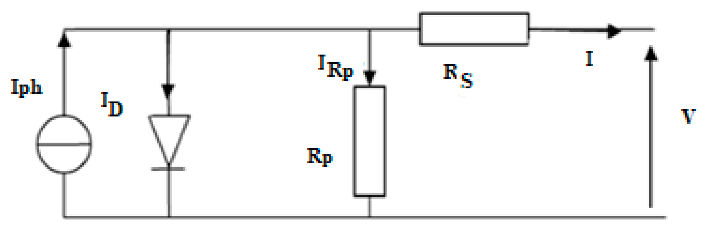
If the main power sources of the hybrid system generate a mixture of alternating and direct current, a mixed coupling integration scheme is preferable. The proposed hybrid power system is composed of a solar panel (Kaneka GSA060), a wind power generator (Air X 400 W), a lithium-ion battery (24 V), and different power converters (an uncontrolled rectifier, a single-phase inverter, a filter, two buck converters, a high gain boost converter, and a bidirectional buck-boost converter). Figure 1 is the scheme of the hybrid system. In the following, the main components are modelled.

2.1. PVG Model

A photovoltaic (PV) module is composed of several PV cells connected in series to increase the value of the total voltage, and several PV modules can be connected in parallel to increase the value of the total current. The PV parameters used in this paper are shown in Table 1.
The electric model of the PV cell is reported in the Figure 2.
The photovoltaic cell (Figure 2) can be described as a set of Equations (1)–(6) that are modelled on the static behavior [15,32,33].
I = I p h I D I R P
I R P = ( V + I R s ) / R p
I D = I S [ e ( ( V + I R s ) / n V t ) 1 ]
I S = K 1 T 3 e ( E g E g K T )
I = I p h I S [ e ( ( V + I R S ) / n V t ) 1 ] I R P
The Iph can be extracted from the short-circuit (SC) condition. In fact, the ISC current is the maximum current generated by the module. It is produced when V = 0. From (6), and remembering that Rs ≪ Rp, it results in Iph ≈ ISC.
Equation (5) becomes:
I = I S C I S [ e ( ( V + I R S ) / n V t 1 ] I R P

2.2. WTG Model

The WTG is composed by a permanent magnet synchronous generator (PMSG) and a turbine connected with an uncontrolled rectifier. This rectifier is built with six diodes that convert a three-phase alternating signal into a DC signal. The specific parameters of the WTG are displayed in Table 2.
The energy delivered by the wind turbine can be calculated as follows:
P t u r b = 1 2 C p ( β , λ ) ρ π R 2 V w 3
where R is the radius of the wind turbine, β is the pitch angle, Cp is the power coefficient, Vw the wind speed, and 𝜆 symbolizes the tip speed ratio defined by:
λ = R ω t u r b V w
where ω t u r b describes the angular velocity of the wind turbine rotor.
The PMSG is usually used for small and medium power wind turbines. The PMSG is modelled by the following equations [15]:
V q = R s i q L q d i q d t + ω e L d i d + ω e λ m
V d = R s i d L d d i d d t + ω e L q i q
The electromagnetic torque Tem is modulated by:
T e m = ( 3 P 2 ) [ ( L d L q ) ] i q i d i q λ m
The electrical angular ω e velocity depends on the number of pole pairs (P), therefore, the mechanical angular velocity is expressed as [15]:
ω e = P 2 ω t u r b
The conversion of an alternating signal into a continuous one is carried out by an uncontrolled rectifier (violet block in Figure 1). The Equations (13)–(15) are the voltages generated by the PMSG, V, the DC output voltage V D C , and the rectifier output current   I DC IDC:
V = V m s i n ( w t )
V d c = 3 3 π V m = 3 6 π λ P w e
I D C = π 6 I A
The DC-DC buck converter is used to decrease the voltage and track the maximum power point supplied by the PVG and WTG. The following equations show the output voltage and current:
V o u t = α b u c k V i n I o u t = ( 1 α b u c k ) I i n
where 0 < α buck < 1.

2.3. Lithium Battery Model

The battery energy storage system (BESS) consists of a bank of lithium-ion type batteries used to reduce the power fluctuations from renewable energy sources and to support stability in the electrical system.
The operation of the battery system is presented by the following equations [39]:
E c h a r g e ( t ) = E B a t t ( t 1 ) + ( E H E S ( t ) E L ( t ) ) η B a t t
E d i s c h a r g e ( t ) = E B a t t ( t 1 ) ( E L ( t ) E H E S ( t ) )
where EL is the load demand (W), EHES is the power delivered from the energy system (W), η Batt is the battery efficiency (%), and Echarge and Edischarge are the battery power in the charging and discharging periods, respectively.
The battery bank capacity can be calculated according to the equation [40]:
C B a t t = D A ( E L E H E S ) / ( η i n v η B a t t D O D )
where DA is the daily autonomy, η inv is the inverter efficiency (%), and DOD is the depth of discharge of the battery (%).

2.4. High-Voltage Gain DC-DC Converter

The coupling of RES and the storage system requires a DC voltage of 400 V for the integration to the grid. To avoid known issues of classical converters (pulsed or discontinuous current, reverse recovery in diode, and so on) a high-voltage DC-DC converter is used (Figure 3) The switches T1 and T2 have the same duty cycle and are shifted by 180 degrees each other.
The capacitor voltages and the output voltage applied are defined as
V o u t = 2 V e 1 ( 1 α 1 ) + 2 V e 2 ( 1 α 2 )
V C 2 = V C 3 = 1 2 V e ( 1 α )
V C 1 = V C 4 = 3 2 V e ( 1 α )
Equation (23) represents the output voltage:
V out = 4 . V e ( 1 α )   with   0.5 < α < 0.9

3. Control Strategies of the Proposed System

This section discusses the design of the following control strategies, reported in the blue box of Figure 1:
  • MPPT fuzzy logic, to produce the maximum power;
  • controller for voltage and current regulation of the battery;
  • fuzzy logic regulator for the high gain DC-DC converter to rise the voltage value from 24 V to 400 V; and
  • active-reactive inverter controller.

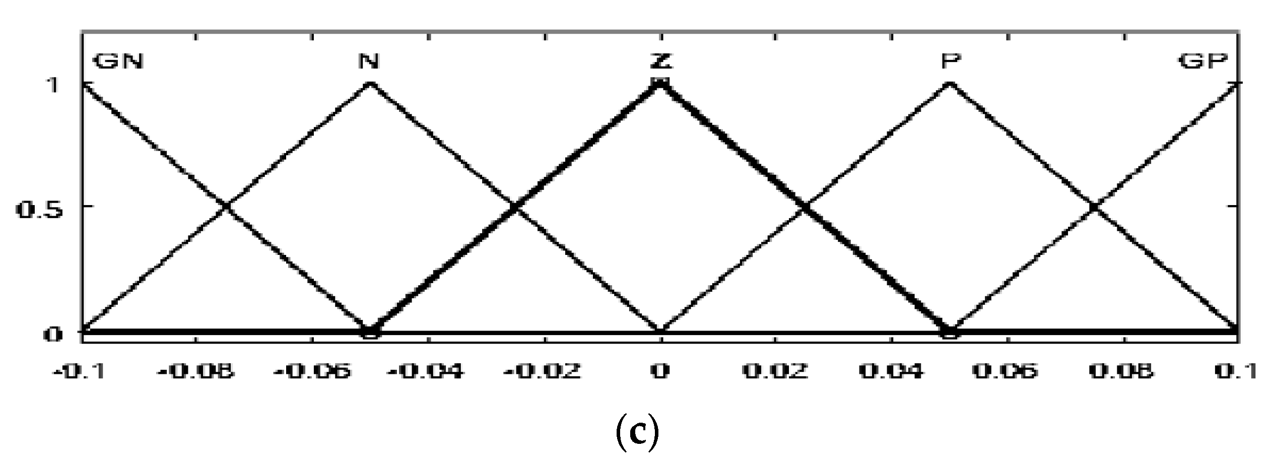
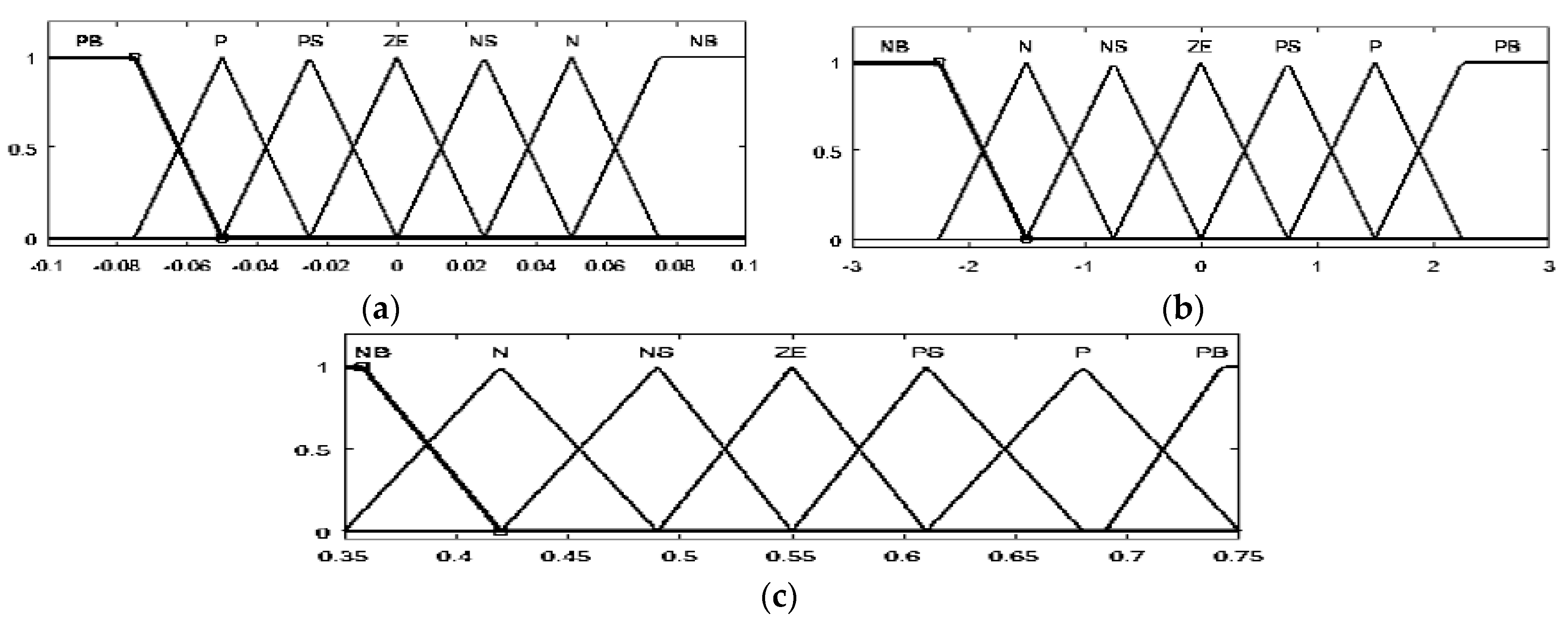
3.1. MPPT Based on Fuzzy Logic Control

The inputs of the fuzzy controller are derived from Equations (24) and (25). The output of the incremental conductance (IC) technique is given by Equation (24).
E ( k ) = I V + dI dV
dE ( k ) = E ( k ) E ( k 1 )
I V = dI dV
Triangular membership functions for the fuzzification and defuzzification processes are used. For inputs E, dE, and Duty output, five membership functions were identified according to the following linguistic variables for the PVG and the WTG: grand negative (GN), negative (N), zero (Z), positive (P), and grand positive (GP). The range for the error is −0.4 to 0.4 (−1 to 1 for the WTG), the range for the error change is −240 to 240 (−1 to 1 for the WTG), and the range for the duty cycle increment is −0.1 to 0.1 (−0.01 to 0.01 for the WTG). The degrees of the membership function of the inputs (PVG and WTG) and output are displayed in Figure 4 and Figure 5, respectively.
Regarding the choice made for the fuzzification of inputs and the defuzzification of output, there are twenty-five inference rules in the fuzzy controller database. We used the Mamdani technique with min-max for fuzzy results. They are summarized in Table 3.

3.2. High-Voltage DC-DC Converter Controller

The control of this converter is usually based on the PI regulator [20], instead, this study proposes a fuzzy logic-based controller. Figure 6 displays the degree of membership function of inputs and output. For both inputs and output, seven membership functions were specified for the fuzzification and defuzzification processes using the following linguistic variables: grand negative (GN), negative (N), negative small (NS), zero (Z), positive small (PS), positive (P), and grand positive (GP).

3.3. AC-DC Inverter Controller

A grid-connected inverter control system consists of two cascading loops, the first is dedicated to stably maintaining the voltage of the DC-link capacitor at the desired value. Thus, the second loop is responsible for power quality and harmonic current compensation. Therefore, it must have a robust behavior to follow the sinusoidal reference with maximum rejection of disturbances. In addition, a phase locked loop (PLL) is developed to ensure the synchronization of the generated reference current with the current control loop. Therefore, this control has two main functions: the first one allows for active power injection into the electrical network and the second one compensates for the reactive power depending on the required energy and the energy produced. However, Ps indicates the apparent power depending on both active and reactive power that is defined by the same equations as below [24]:
P S = P + j Q
where
P = V g ω L ( V inv δ )
Q = V g ω L ( ( V inv cos ( δ ) ) V g )
This command requires two PI regulators: one to control the DC voltage in the DC bus to maintain a voltage constant and the other one to control the current injected into this bus. This block is used to explain and model the RTL architecture of the PQ control for the implementation on the FPGA board.

3.4. PI Controller for the Battery System

The method used for the optimal control of the battery is based on two PI regulators. The first one ensures the charge/discharge current control and the second one is intended for the voltage control. The model of the battery controller is shown in Figure 7.

4. Architecture of the Fuzzy Logic Controller on FPGA

This section explains how the previous controllers were implemented on an FPGA. Figure 8 shows a method to modify the values for the FPGA board consisting of two parts: the first shows the decimal part and the second shows the fractional part. In addition, we must calculate the number of bits (m) that denotes the integer part and the other forms of the fractional part (n). A number written in the fixed point is mentioned.
The Mamdani’s method is the most popular technique dedicated to FLC. The fuzzy rule is proven in the following equation:
μ c ( y ) = m a x [ m i n [ μ A 1 k ( x 1 ) , μ A 2 k ( x 2 ) ] ]
where μ c ( y ) is the compute output values and k = 1, 2, …, 25.
In Figure 9, the steps of the proposed control are explained in detail.
The Mamdani technique simplifies the processing of materials thanks to its simple min-max structure. A summary of the internal structure of the controller can be found in Figure 4. However, the fuzzification of the two input parameters generates the appropriate linguistic values and membership functions (B1…B5) and (B11…B15). In addition, the association of antecedent pairs in the rule structure is essentially based on an operator AND logic. Then, all rules are combined in a max operation via the max block of the diagram. Therefore, the weighted average approach is recognized as one of the defuzzification processes that is suitable for implementation on hardware. Since the output membership functions are usually symmetrical, the fuzzy average can be applied as a weighting for the defuzzification process. Simultaneously, this method is composed of two arithmetic operations: multiplication operations with a constant process and a single division process.
The inputs/outputs signal of the ADC and the DAC converters situated on the Spartan 3E FPGA board are represented by 12 bits. As a result, the length of the integer and decimal part of each input/output signal is chosen according to the value of the signal to be displayed. For example, the input signals may be a 12-bit vector (m = 7, n = 5). As a result, the value of the open circuit voltage should not be greater than the open circuit voltage, such as 92 V. In addition, a 0 to 1 output value of the duty cycle was obtained, so the duty cycle was defined as 12 bits, and we decided to use a 10-bit representation for the decimal part.
The high-voltage gain DC-DC converter was also controlled by fuzzy logic. With respect to inputs and output, seven membership functions were defined for the fuzzification and defuzzification processes depending on the following linguistic variables: grand negative (GN), negative (N), negative small (NS), zero (Z), positive small (PS), positive (P) and grand positive (GP). The same methodology of the FLC structure shown in the functional diagram in Figure 9 was implemented to represent the fuzzy controller architecture designed for the proposed converter.

5. Simulation and Results

This section explains the simulation results of different components of the hybrid system under the strategies control and the architecture of the fuzzy logic controller to be implemented on FPGA. The experimental validation of the combined PV-wind power system is available in [15].

5.1. Simulation Results in Matlab Simulink

To evaluate the proposed strategies and their efficacy, we implemented the whole hybrid system in the MATLAB/SIMULINK environment. The global system (Figure 1) contains the PVG composed of four parallel-connected PV modules and a WTG (400 W). Each source is associated with a buck converter. In addition, the battery is associated to the bidirectional converter. This hybrid system is coupled with the converter, filter, and the grid.

5.1.1. Simulation Results of the PVG

The PV array is coupled to the buck converter, which is controlled by MPPT using a FLC. During the time of simulation, the solar radiation varied between 700 W and 1000 W. A temperature value of 25 °C was assigned. The purpose of the buck converter is to lower the voltage to 24 V and to recover the maximum power supplied by the PVG during the change of solar radiation. FLC based on IC works very well and tracks MPP while environmental conditions change. It also shows good precision and speed.
Figure 10 shows the profile of the radiation, the duty cycle, and the power referred to the PVG.

5.1.2. Simulation Results of the WTG

The WTG is constituted by the wind turbine (WT) and the PMSG coupled to the uncontrolled rectifier, linked with the buck converter and controlled by the FLC. Figure 11 displays the proportional variation between the wind speed, the duty cycle required by the converter, and the WTG output power. Therefore, the MPPT can be exploited to obtain the maximum power without large power variations, despite the significant differences in wind speed.

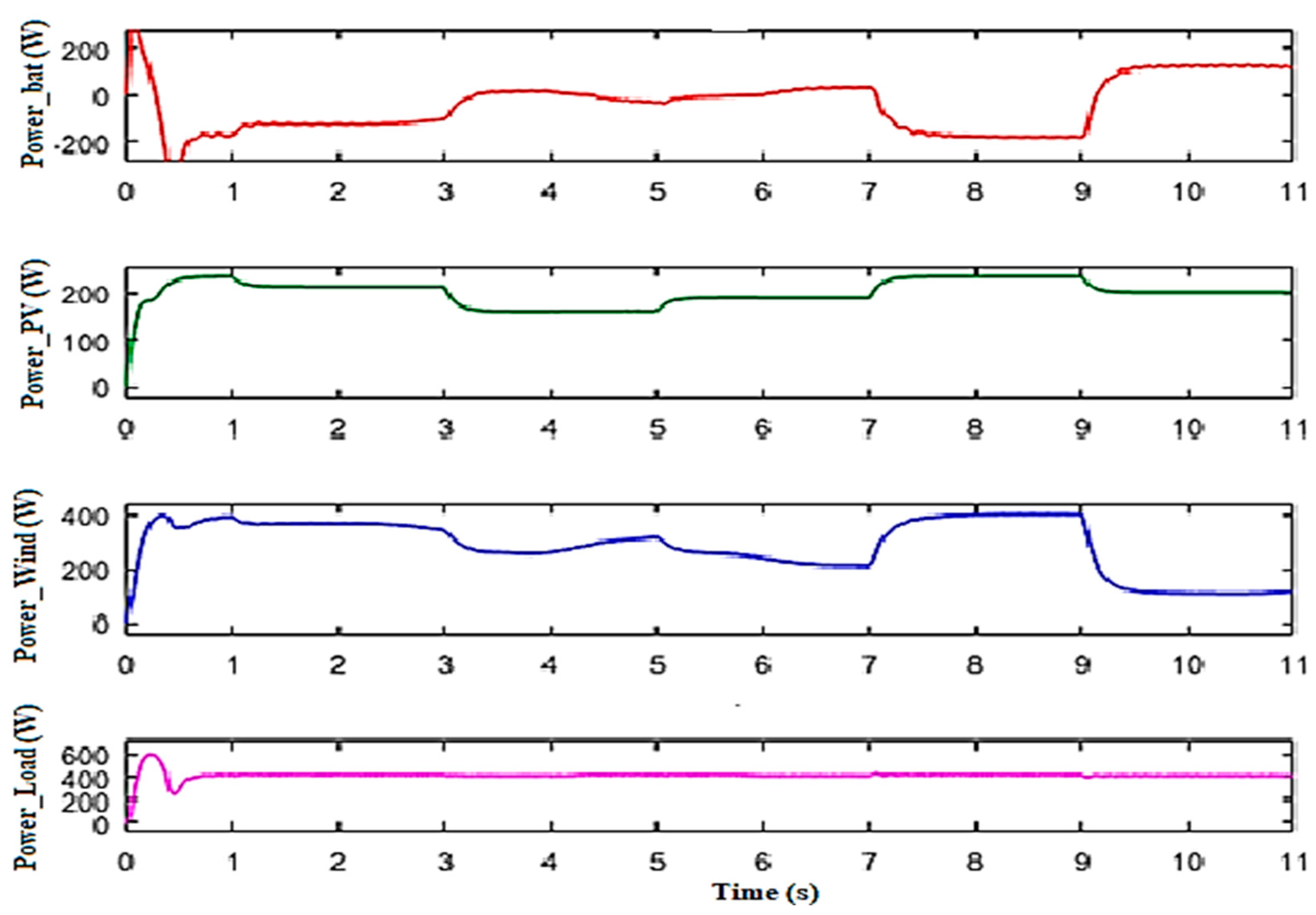
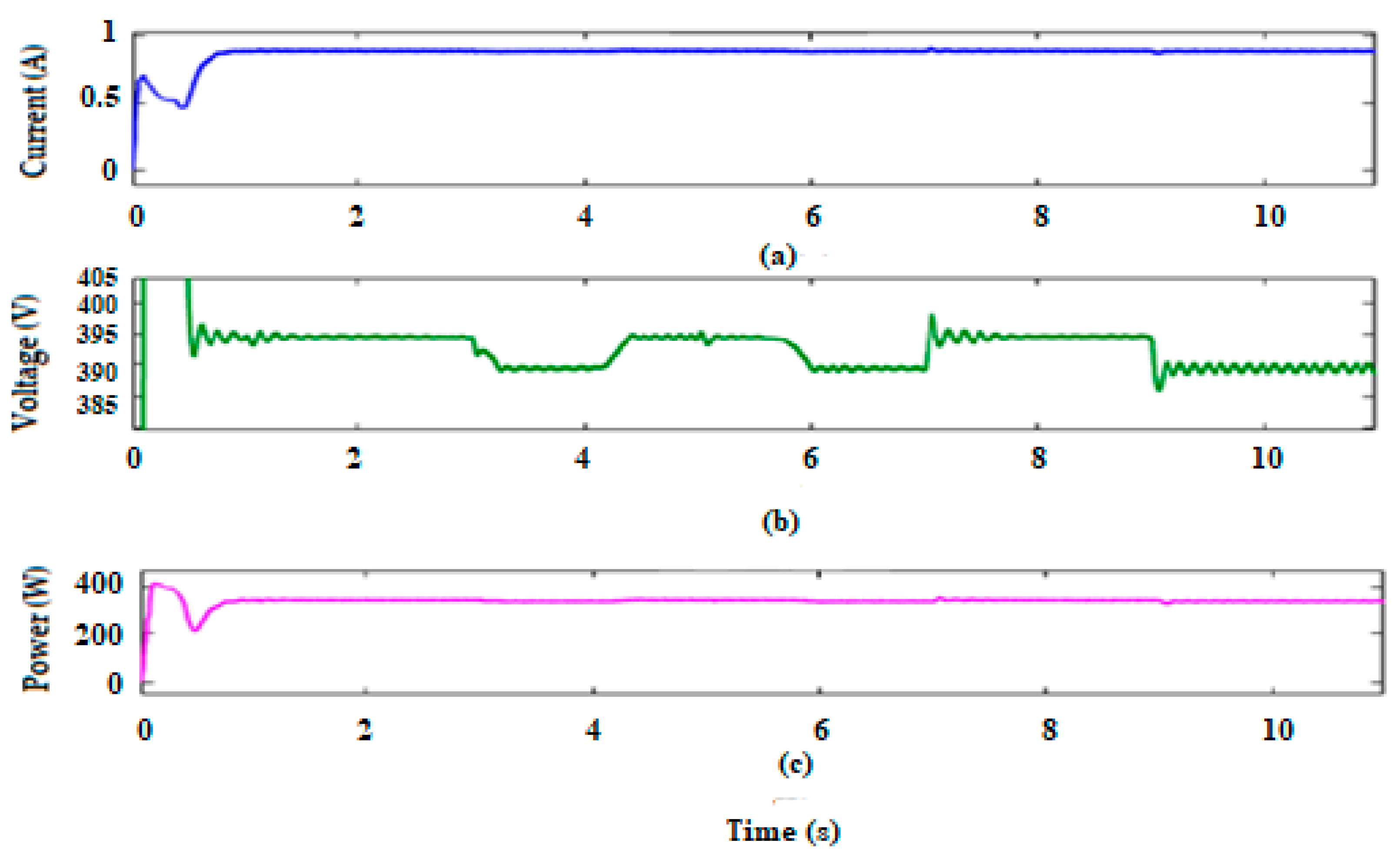
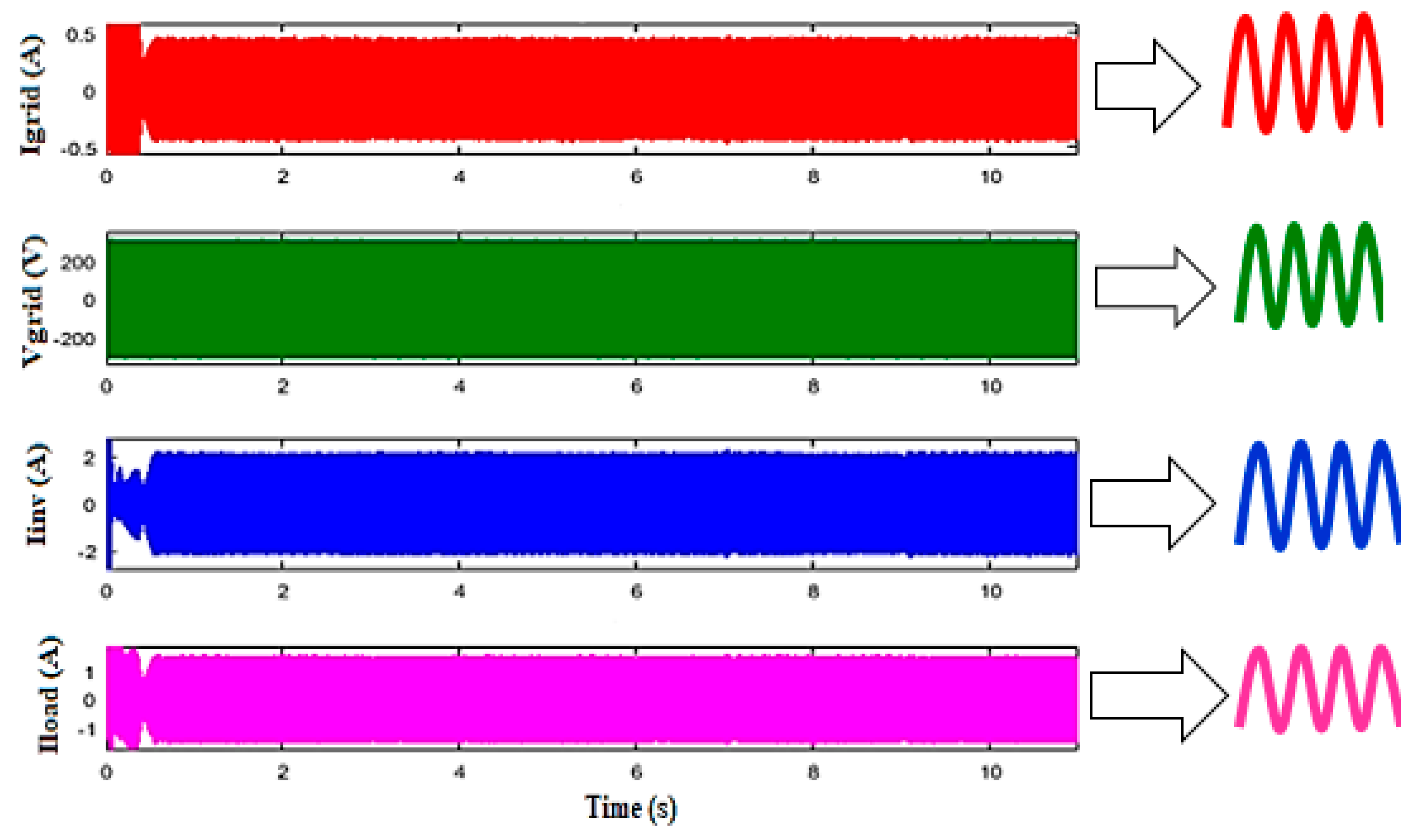
5.1.3. Various Simulation Results of the Proposed System

The output simulated power generated by the PVG, WTG, and battery is displayed in Figure 12. It can be observed that the battery charge and discharge are estimated as the difference between the total power provided by the renewable sources and the power transferred to the load (power load).
Figure 12 presents the simulation results of the power provided by the PVG, the WTG, and the battery, and the power injected into the DC bus. The battery charge and discharge are correctly regulated, using the difference between the power supplied by the renewable sources and the power injected into the DC bus.
For the battery control, the DC bus voltage must be kept constant. It can be observed that the voltage is tuned between 22 V and 24 V, regardless of the variations in wind speed. The combined output power, current, and voltage results of the DC bus are displayed in Figure 13.
To connect the hybrid system to the power grid, a 400 V voltage should be supplied at the input of the inverter at a frequency of 50 HZ. This is carried out by using the proposed converter that increases the voltage from 24 V to 400 V. Therefore, the output voltage, current, and power are described in Figure 14, while Figure 15 presents the waveforms of the voltage and current injected into the grid and required by the alternating load (300 W).
The results show that the sum of the absorbed current by the AC load and the current injected into the grid is effectively equal to the current provided by the hybrid power system. The synchronization of the voltage and current injected to the grid is detailed in Figure 16.

5.2. Synthesis of Commands Proposed on the FPGA Card

After development in very high speed integrated circuits hardware description anguage (VHDL) of the different control strategies, we needed to synthesize the VHDL codes and check that the FPGA board was able to support these commands. Table 4 shows the hardware resources we used for each command.
The summary report shows the percentage of hardware resources usage required by various commands compared to the existing resources in the FPGA board. Therefore, the reserved hardware resources in the FPGA board are considered acceptable and not encumbered, with a utilization rate of the slice LUTs of 13% and 68% of the number of inputs and outputs of the existing set in the FPGA board.

6. Conclusions

This paper presents the modeling and simulation of a control system composed by five controllers for a grid-connected PV/wind/battery hybrid with AC load. The proposed system was validated in MATLAB/SIMULINK and ISE Design for implementation of the code in the FPGA card.
More precisely, a control strategy based on MPPT FLC using the algorithm of the incremental conductance was created to capture the maximum power extracted from the PVG and WTG generators. Additionally, a FLC that maintains a fixed DC link voltage at the output of the proposed converter was included. While the PQ control was implemented to control the inverter, the battery controller employed two PI controls: the first was designed to regulate the DC bus voltage and the second was created to manage the current controller.
The integration of a high-voltage gain DC-DC converter allowed us to increase the 24 V voltage generated by the DC bus to a voltage appropriate for the inverter of about 400 V and to minimize power losses to ensure maximum efficiency of the proposed system.
The challenges and non-linearity of PV and wind turbine (WT) systems are influenced by solar radiation, temperature, and wind speed, resulting in power losses and reduced efficiency. To obtain a fast response time and to take into account time constraints, we developed and simulated different architectures to facilitate VHDL programming and make control executable in real time. Thus, different controllers were developed and simulated in VHDL. The innovative design presented in this work requires a small unit of energy sources and presents an appropriate solution for domestic applications.
Future work should aim to experimentally verify the feasibility of the new control scheme for real-time applications of hybrid power systems.

Author Contributions

Conceptualization, M.Y.A.; methodology, M.Y.A.; software, J.R.; writing—original draft preparation, M.Y.A.; visualization, A.M.; investigation, M.Y.A.; writing—reviewing and editing, S.V., J.R. All authors have read and agreed to the published version of the manuscript.

Funding

This research received no external funding.

Institutional Review Board Statement

Not applicable.

Informed Consent Statement

Not applicable.

Data Availability Statement

Not applicable.

Acknowledgments

Not applicable.

Conflicts of Interest

The authors declare no conflict of interest.

Abbreviations

PVGPhotovoltaic generator
WTGWind turbine generator
MPPTMaximum power point tracking
NCONumerically controlled oscillator
FPGAField programmable gate arrays
ISEIntegrated synthesis environment

Nomenclature

IThe output current of the PVG
IphThe photocurrent of the solar panel
IDThe diode current of the solar panel
aThe ideality factor
kThe Botzman constant
K1The temperature coefficient in current
TThe temperature
TrefThe reference temperature
qThe elementary charge in Coulombs
GThe irradiance
GrefThe reference irradiance
EgThe gap energy
VThe voltage
PThe power
TThe switch
DCDirect current
ACAlternating current

References

  1. Petreus, D.; Daraban, S.; Cirstea, M.N. Modular Hybrid Energy Concept Employing a Novel Control Structure Based on a Simple Analog System. Adv. Electr. Comput. Eng. 2016, 16, 3–10. [Google Scholar] [CrossRef]
  2. Barote, L.; Marinescu, C. Modeling and Operational Testing of an Isolated Variable Speed PMSG Wind Turbine with Battery Energy Storage. Adv. Electr. Comput. Eng. 2012, 12, 69–76. [Google Scholar] [CrossRef]
  3. Sakthivel, B.K.; Devaraj, D. Modelling, Simulation and Performance Evaluation of Solar PV-Wind Hybrid Energy System. IEEE Electr. Electron. Signals Commun. Optim. 2015, 24–25. [Google Scholar]
  4. Grouz, F.; Sbita, L. A safe and easy methodology for design and sizing of a stand-alone hybrid PV-wind system. In Proceedings of the 2014 International Conference on Electrical Sciences and Technologies in Maghreb (CISTEM), Tunis, Tunisia, 3–6 November 2014; pp. 1–8. [Google Scholar]
  5. Yang, B.; Li, W.H.; Zhao, Y.; He, X.N. Design and Analysis of a Grid-Connected Photovoltaic Power System. IEEE Trans. Power Electron. 2010, 25, 992–1000. [Google Scholar] [CrossRef]
  6. Borowy, B.S.; Salameh, Z.M. Optimum Photovoltaic Array Size for a Hybrid Wind/PV System. IEEE Trans. Energy Convers. 2002, 9, 482–488. [Google Scholar] [CrossRef]
  7. Chen, Y.-M.; Liu, Y.-C.; Hung, S.-C.; Cheng, C.-S. Multi-Input Inverter for Grid-Connected Hybrid PV/Wind Power System. IEEE Trans. Power Electron. 2007, 22, 1070–1077. [Google Scholar] [CrossRef]
  8. Loukriz, A.; Haddadi, M.; Messalti, S. Simulation and experimental design of a new advanced variable step size Incremental Conductance MPPT algorithm for PV systems. ISA Trans. 2016, 62, 30–38. [Google Scholar] [CrossRef] [PubMed]
  9. Baghdadi, F.; Mohammedi, K.; Diaf, S.; Behar, O. Feasibility study and energy conversion analysis of stand-alone hybrid renewable energy system. Energy Convers. Manag. 2015, 105, 471–479. [Google Scholar] [CrossRef]
  10. Mahesh, A.; Sandhu, K.S. Hybrid wind/photovoltaic energy system developments: Critical review and findings. Renew. Sustain. Energy Rev. 2015, 52, 1135–1147. [Google Scholar] [CrossRef]
  11. Messalti, S.; Harrag, A.; Loukriz, A. A new variable step size neural networks MPPT controller: Review simulation and hardware implementation. Renew. Sustain. Energy Rev. 2017, 68, 221–233. [Google Scholar] [CrossRef]
  12. Arfaoui, J.; Feki, E.; Rabhi, A.; Mami, A. Optimization of Scaling Factors of Fuzzy–MPPT Controller for Stand-alone Photovoltaic System by Particle Swarm Optimization. In Proceedings of the 8th International Conference on Sustainability in Energy and Buildings, SEB-16, Turin, Italy, 11–13 September 2016. [Google Scholar]
  13. Othmani, H.; Mezghani, D.; Belaid, A.; Mami, A. New Approach of Incremental Conductance Algorithm for Maximum Power Point Tracking Based on Fuzzy Logic. Int. J. Grid Distrib. Comput. 2016, 9, 121–132. [Google Scholar] [CrossRef]
  14. Yilmaz, U.; Kircay, A.; Borekci, S. PV system fuzzy logic MPPT method and PI control as a charge controller. Renew. Sustain. Energy Rev. 2018, 81, 994–1001. [Google Scholar] [CrossRef]
  15. Riahi, J.; Vergura, S.; Mezghani, D.; Mami, A. A combined PV-wind energy system for an energy saving greenhouse. In Proceedings of the 2020 IEEE International Conference on Environment and Electrical Engineering and 2020 IEEE Industrial and Commercial Power Systems Europe (EEEIC/I&CPS Europe), Madrid, Spain, 9–12 June 2020; pp. 1–6. [Google Scholar]
  16. Nguyen, M.K.; Duong, T.D.; Lim, Y.C.; Kim, Y.J. Isolated Boost DC-DC Converter with Three Switches. IEEE Trans. Power Electron. 2018, 33, 1389–1398. [Google Scholar]
  17. Lu, Y.; Wu, H.; Sun, K.; Xing, Y. A Family of Isolated Buck-Boost Converters Based on Semi-active Rectifiers for High Output Voltage Applications. IEEE Trans. Power Electron. 2016, 31, 6327–6340. [Google Scholar] [CrossRef]
  18. Gandhi, V.I.; Subramaniyaswamy, V.; Logesh, R. Topological review and analysis of DC-DC boost converters. J. Eng. Sci. Technol. 2017, 12, 1541–1567. [Google Scholar]
  19. Babaei, E.; Saadatizadeh, Z. High voltage gain dc–dc converters based on coupled inductors. IET Power Electron. 2018, 11, 434–452. [Google Scholar] [CrossRef]
  20. Baddipadiga, B.P.R.; Prabhala, V.A.K.; Ferdowsi, M. A Family of High-Voltage-Gain DC–DC Converters Based on a Generalized Structure. IEEE Trans. Power Electron. 2018, 33, 8399–8411. [Google Scholar] [CrossRef]
  21. Cóbreces, S.; Griñó, R. Hysteretic control of grid-side current for a single-phase LCL grid-connected voltage source converter. Math. Comput. Simul. 2016, 130, 194–211. [Google Scholar] [CrossRef] [Green Version]
  22. Wu, F.; Li, X.; Duan, J. Improved Elimination Scheme of Current Zero-Crossing Distortion in Unipolar Hysteresis Current Controlled Grid-Connected Inverter. IEEE Trans. Ind. Inform. 2015, 11, 1111–1118. [Google Scholar] [CrossRef]
  23. Yaramasu, V.; Wu, B. Model Predictive Control of Wind Energy Conversion Systems; John Wiley & Sons: Hoboken, NJ, USA, 2016. [Google Scholar]
  24. Cunningham, S.C. Theory, Simulation, and Implementation of Grid Connected Back to Back Converters Utilizing Voltage Oriented Control. Master’s Thesis, University of Wisconsin-Milwaukee, Milwaukee, WI, USA, 2017. [Google Scholar]
  25. Komurcugil, H.; Altin, N.; Ozdemir, S.; Sefa, I. Lyapunov-Function and Proportional-Resonant Based Control Strategy for Single-Phase Grid-Connected VSI with LCL Filter. IEEE Trans. Ind. Electron. 2016, 63, 2838–2849. [Google Scholar] [CrossRef]
  26. Abusara, M.; Sharkh, S.M.; Zanchetta, P. Pericle Control of grid-connected inverters using adaptive repetitive and proportional resonant schemes. J. Power Electron. 2015, 15, 518–529. [Google Scholar] [CrossRef] [Green Version]
  27. Chettibi, N.; Mellit, A. Fpga-based real time simulation and control of grid-connected photovoltaic systems. Simul. Model. Pract. Theory 2014, 43, 34–53. [Google Scholar] [CrossRef]
  28. Chettibi, N.; Mellit, A. Study on Control of Hybrid Photovoltaic-Wind Power System Using Xilinx System Generator. In Solar Photovoltaic Power Plants; Springer: Singapore, 2019; pp. 97–120. [Google Scholar]
  29. Badwawi, R.A.; Abusara, M.; Mallick, T. A Review of Hybrid Solar PV and Wind Energy System. Smart Sci. 2015, 3, 127–138. [Google Scholar] [CrossRef]
  30. Mangu, B.; Akshatha, S.; Suryanarayana, D.; Fernandes, B.G. Grid-Connected PV-Win-Battery Based Multi-Input Transformer Coupled Bidirectional DC-DC Converter for Household Applications. IEEE J. Emerg. Select. Topics Power Electron. 2016, 4. [Google Scholar] [CrossRef]
  31. Basaran, K.; Cetin, N.S.; Borekci, S. Energy management for on-grid and off-grid wind/PV and battery hybrid systems. IET Renew. Power Gener 2017, 11, 642–649. [Google Scholar] [CrossRef]
  32. Jomaa, M.; Allani, M.Y.; Tadeo, F.; Mami, A. Design and control of the hybrid system PV-Wind connected to the DC load. In Proceedings of the 2018 9th International Renewable Energy Congress (IREC), Hammamet, Tunisia, 20–22 March 2018; pp. 1–6. [Google Scholar]
  33. Allani, M.Y.; Jomaa, M.; Mezghani, D.; Mami, A. Modelling and simulation of the hybrid system PV-wind with MATLAB/SIMULINK. In Proceedings of the 2018 9th International Renewable Energy Congress (IREC), Hammamet, Tunisia, 20–22 March 2018; pp. 1–6. [Google Scholar]
  34. Chong, L.W.; Wong, Y.W.; Rajkumar, R.K.; Rajkumar, R.K.; Isa, D. Hybrid energy storage systems and control strategies for stand-alone renewable energy power systems. Renew. Sustain. Energy Rev. 2016, 66, 174–189. [Google Scholar] [CrossRef]
  35. Fathima, A.H.; Palanisamy, K. Optimization in microgrids with hybrid energy systems—A review. Renew. Sustain. Energy Rev. 2015, 45, 431–446. [Google Scholar] [CrossRef]
  36. Benlahbib, B.; Bouarroudj, N.; Mekhilef, S.; Abdelkrim, T.; Lakhdari, A.; Bouchafaa, F. A fuzzy logic controller based on maximum power point tracking algorithm for partially shaded PV array-experimental validation. Elektronika ir Elektrotechnika 2018, 4, 38–44. [Google Scholar] [CrossRef] [Green Version]
  37. Lee, J.; Kim, Y.S. Sensorless fuzzy-logic-based maximum power point tracking control for a small-scale wind power generation system with a switched mode rectifier. IET Renew. Power Gener. 2016, 10, 194–202. [Google Scholar] [CrossRef]
  38. Riahi, J.; Vergura, S.; Mezghani, D.; Mami, A. Intelligent Control of the Microclimate of an Agricultural Greenhouse Powered by a Supporting PV System. Appl. Sci. 2020, 10, 1350. [Google Scholar] [CrossRef] [Green Version]
  39. Borowy, B.S.; Salameh, Z.M. Methodology for optimally sizing the combination of a battery bank and PV array in a Wind/PV hybrid system. IEEE Trans. Energy Convers. 1996, 11, 367–373. [Google Scholar] [CrossRef]
  40. Daud, A.K.; Ismail, M.S. Design of isolated hybrid systems minimizing costs and pollutant emissions. Renew. Energy 2012, 44, 215–224. [Google Scholar] [CrossRef]
Figure 1. Scheme of the hybrid system.
Energies 14 02108 g001
Figure 2. Electric model of a PV cell.
Energies 14 02108 g002
Figure 3. The electrical circuit of a DC-DC converter with high-voltage gain.
Energies 14 02108 g003
Figure 4. The membership function of E (a), dE (b), and duty cycle (c) for PVG.
Energies 14 02108 g004aEnergies 14 02108 g004b
Figure 5. The membership function of E (a), dE (b), and duty cycle (c) for WTG.
Energies 14 02108 g005
Figure 6. The membership function of E (a), dE (b) and duty cycle (c) of the high-gain DC-DC converter.
Energies 14 02108 g006
Figure 7. Simulink model of battery control.
Energies 14 02108 g007
Figure 8. Representation of the fixed point digit.
Energies 14 02108 g008
Figure 9. The functional diagram of the proposed control.
Energies 14 02108 g009
Figure 10. Waveforms of solar radiation, duty cycle, and power of the PVG.
Energies 14 02108 g010
Figure 11. Waveforms of wind speed, duty cycle, and output power of the WTG.
Energies 14 02108 g011
Figure 12. Output power profiles generated by the different sources and the DC bus.
Energies 14 02108 g012
Figure 13. The DC bus output current (a), voltage (b), and power (c).
Energies 14 02108 g013
Figure 14. Waveforms of the output current (a), voltage (b), and power (c) of the DC-DC high gain converter.
Energies 14 02108 g014
Figure 15. The profile of alternating voltages–currents.
Energies 14 02108 g015
Figure 16. The voltage–current fed into the grid.
Energies 14 02108 g016
Table 1. The characteristic parameters of the photovoltaic (PV) panel Kaneka G-SA060 [32,33,38].
Parameters of PVValues and Units
Cells per Module61
Pmax60.3 W
VPV at Pmax67 V
IPV at Pmax0.9 A
VO (Open Circuit Voltage)91.8 V
IS (Short Circuit Current)1.19 A
a2.1922
RS (Series Resistance)5.8 ohms
RSh (Shunt Resistance)254.8 ohms
Table 2. Main parameters of the WTG.
ParametersValues
Rotor Diameter46 in (1.15 m)
Weight13 lb (5.85 kg)
Start Up Wind Speed15.6 mph (7.5 m/s)
Voltage24 VDC
Rated Power386 W at 28 mph (12.5 m/s)
Base Rotational Speed1700 rpm
Initial Rotational Speed500 rpm
Rotor Diameter46 in (1.15 m)
Weight13 lb (5.85 kg)
Start Up Wind Speed15.6 mph (7.5 m/s)
Voltage24 VDC
Rated Power386 W at 28 mph (12.5 m/s)
Table 3. Fuzzy controller inference rules.
E\dEGNNZPGP
GNZZGPGPGP
NZZPPP
ZPZZZN
PNNNZZ
GPGNGNGNZZ
Table 4. Device utilization summary of the synthesis report for different control strategies.
Logic UtilizationPVG ControlWTG ControlConverter ControlBattery ControlInverter ControlSum
Number of Slice Registers0%0%0%0%0%0%
Number of Slice Lookup Table LUTs2%2%4%4%1%13%
Number of Fully used Lookup TableFlip-Flop LUT-FF Pairs0%0%0%0%28%28%
Number of Bonded Input Output Block IOBs7%7%9%9%36%68%
Number of Global Clock Buffer(BUFG)/Global Clock Buffer Control (BUFGCTRLs)3%3%3%3%6%18%
Publisher’s Note: MDPI stays neutral with regard to jurisdictional claims in published maps and institutional affiliations.

