
Wireless Power Transfer Technologies Applied to Electric Vehicles: A Review


Abstract
1. Introduction
- Automatic operation without driver intervention. The process can be scheduled, and it can happen even without the presence of the vehicle owner. This feature reveals itself as convenient to promote the participation of the EVs in the V2G operations. Some software appliances can be designed and implemented to program the charges and set the user preferences.
- Safer charge. In case of electric cars, conductive charge is supported by cables carrying high electrical current. This could become a serious risk, especially when adverse weather conditions take place. As this conductor is avoided by wireless chargers, this type of charger becomes safer from the driver’s point of view. As a counterpart, magnetic or electric fields involved in the wireless power transfer must be restricted to the controlled levels to guarantee that they are not harmful.
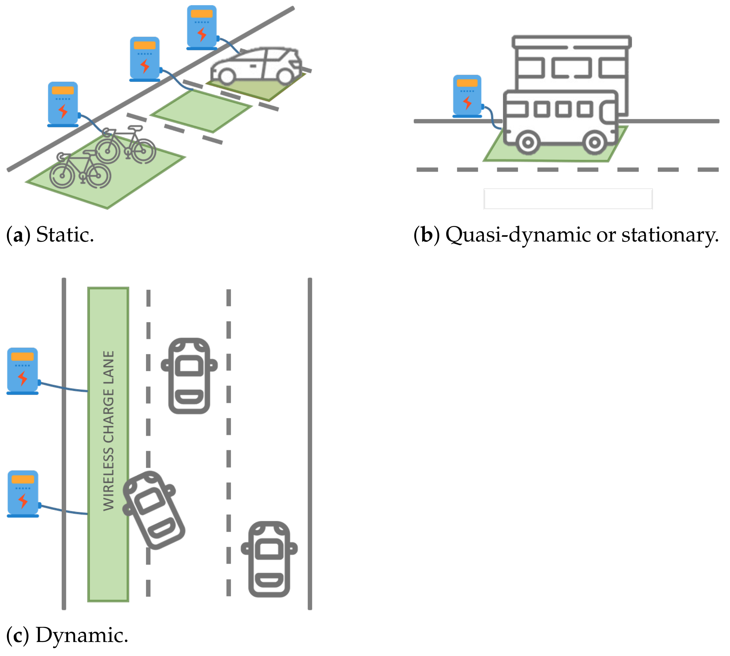
- Dynamic or on-the-move charge. As the power source and the receiver are not physically connected, the EVs can be charged in more situations if they use wireless chargers. Thus, the use of wireless chargers extends the possibility of performing a static charge (when the EV is parked) to scenarios where the car is temporally stopped (e.g., waiting for a traffic light) or on the move. If this kind of charge are available in more road sectors, this will imply that the battery of the EVs can be charged more frequently while moving and it could be smaller and cheaper.
- Transferred power. WPT technology can be used to transmit up to 1 kW for light-duty vehicles, to transfer 1–100 kW for medium power EV or even to send more than 100 kW for high-power EVs. For very-low-power requirements, the system may directly power the vehicle instead of recharging the battery. In addition to this tendency, the power level impacts on two main issues. First, the devices on the power electronics need to support the switching frequency and the demanded power levels. Second, the power levels involved in the transfer usually sets the criterion to follow in the design. In this sense, the maximum power transfer theorem is applied for low-power applications whereas the efficiency is more relevant for high power levels.
- V2X-enabled power transfer, i.e., the compliance or not with the Vehicle-to-Everything (V2X) context. By this criterion, we define the sense of the power flow leading to unidirectional or bi-directional chargers. The traditional chargers have a power transfer with a unique sense from a power system to the battery but it is also possible to discharge the EVs to support the grid, another vehicle or device. In this last case, the power electronics must be designed to be bi-directional.
- Gap, i.e., the distance separating the power source and the receiver. In EV wireless chargers, we can find a wide range for the gap. In [17], the receiver is installed in the kickstand of a bicycle and the transmitter is on the pavement. Both power extremes are in contact with 0 cm as the gap. For electric cars, SAE establishes the term coil ground clearance as the gap. In particular, the organization defines three types of classes according to this parameter: Z1-class ( 100 mm < gap < 150 mm), Z2-class (140 mm < gap < 210 mm) and Z3-class (170 mm < gap < 250 mm). For aerospace applications, the gap can reach up to several meters [18].
- Capability to work with misalignment. During the design of a charger, the transmitter and the receiver are assumed to be in a predefined position. However, the conventional use of the charger may be in situations where the transmitter and/or the receiver are not in those expected placed. As a result, both extremes are misaligned. Some WPT technologies are still able to work with misalignment. However, other technologies need to reconfigure the transmitter to modify the power beam so it is adjusted to the current position of the receiver.
- Potential existence of intermediate objects. The WPT technologies operate with different ranges of wavelengths. This makes them capable or not to transmit the power when intermediate objects are in the gap. Safety issues may arise when this eventuality takes place.
- Stationary/Mobile receiver, if we set the requirement that the WPT system should be able to transfer power when the receiver is in an unspecific position before or during the charging process. This feature is especially relevant for on-the-move charge.
2. Charging Operation Modes: Static, Stationary and Dynamic
3. WPT Technologies
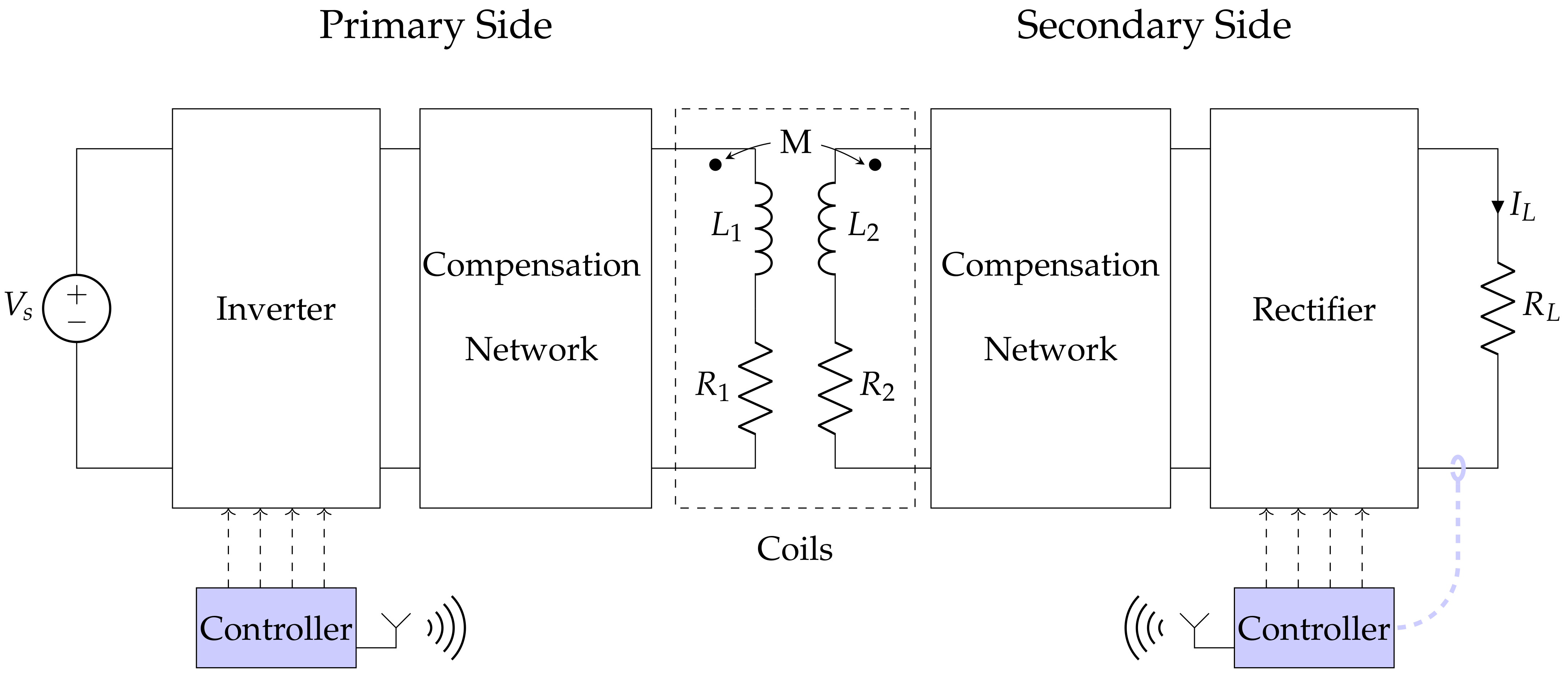
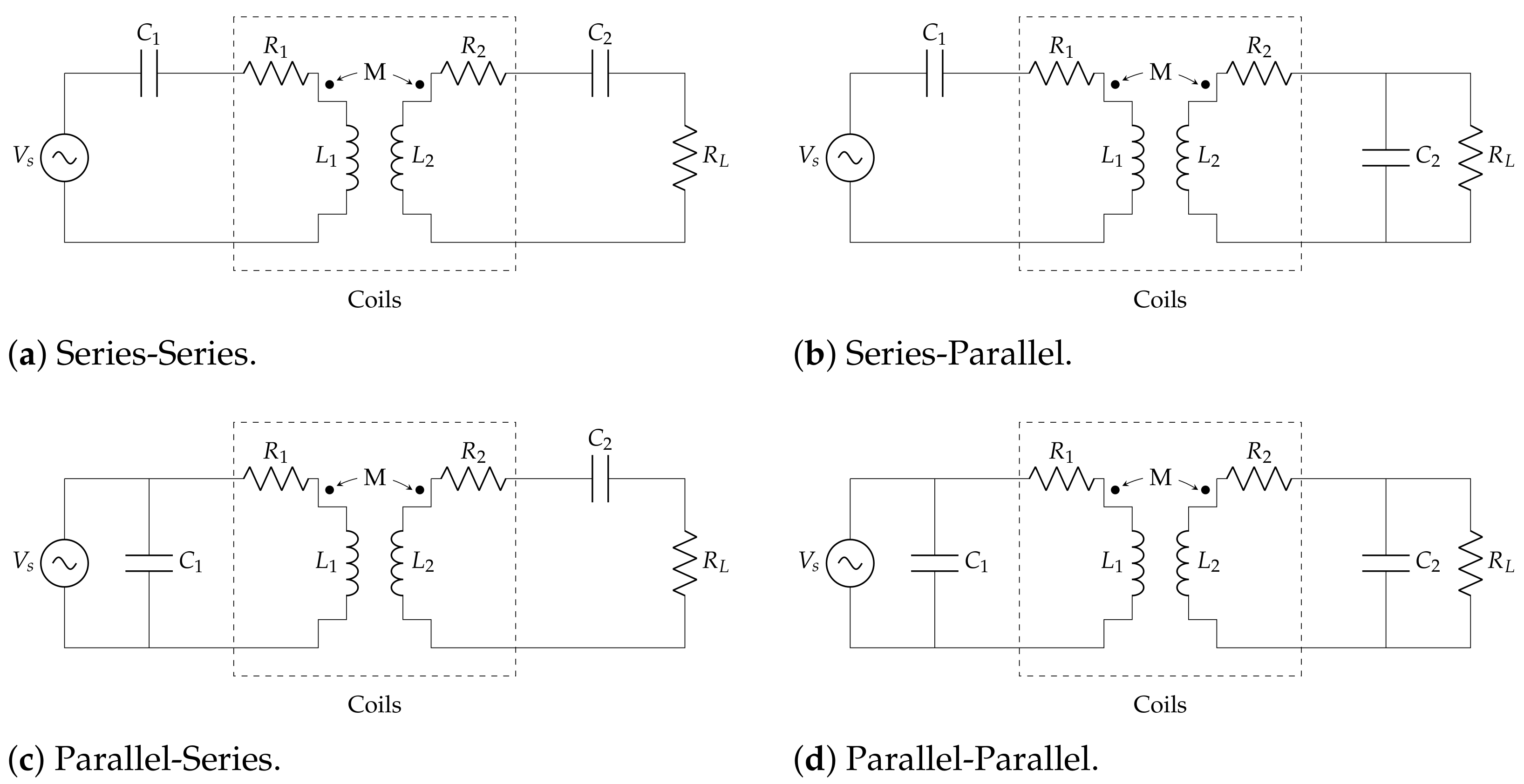
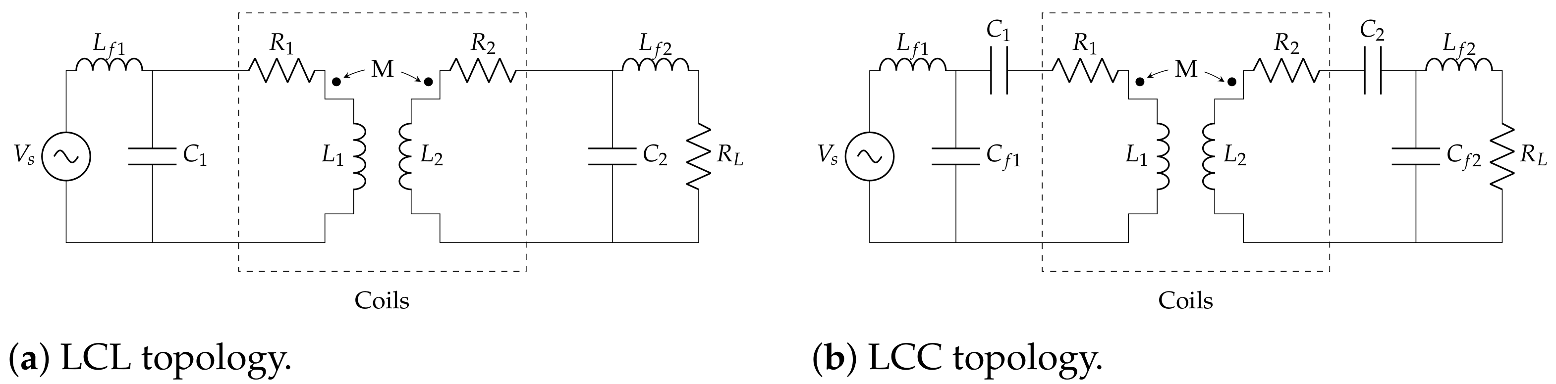
3.1. Magnetic Resonant WPT

| Topology | Efficiency | ||
|---|---|---|---|
| SS | |||
| SP | |||
| PS | |||
| PP |
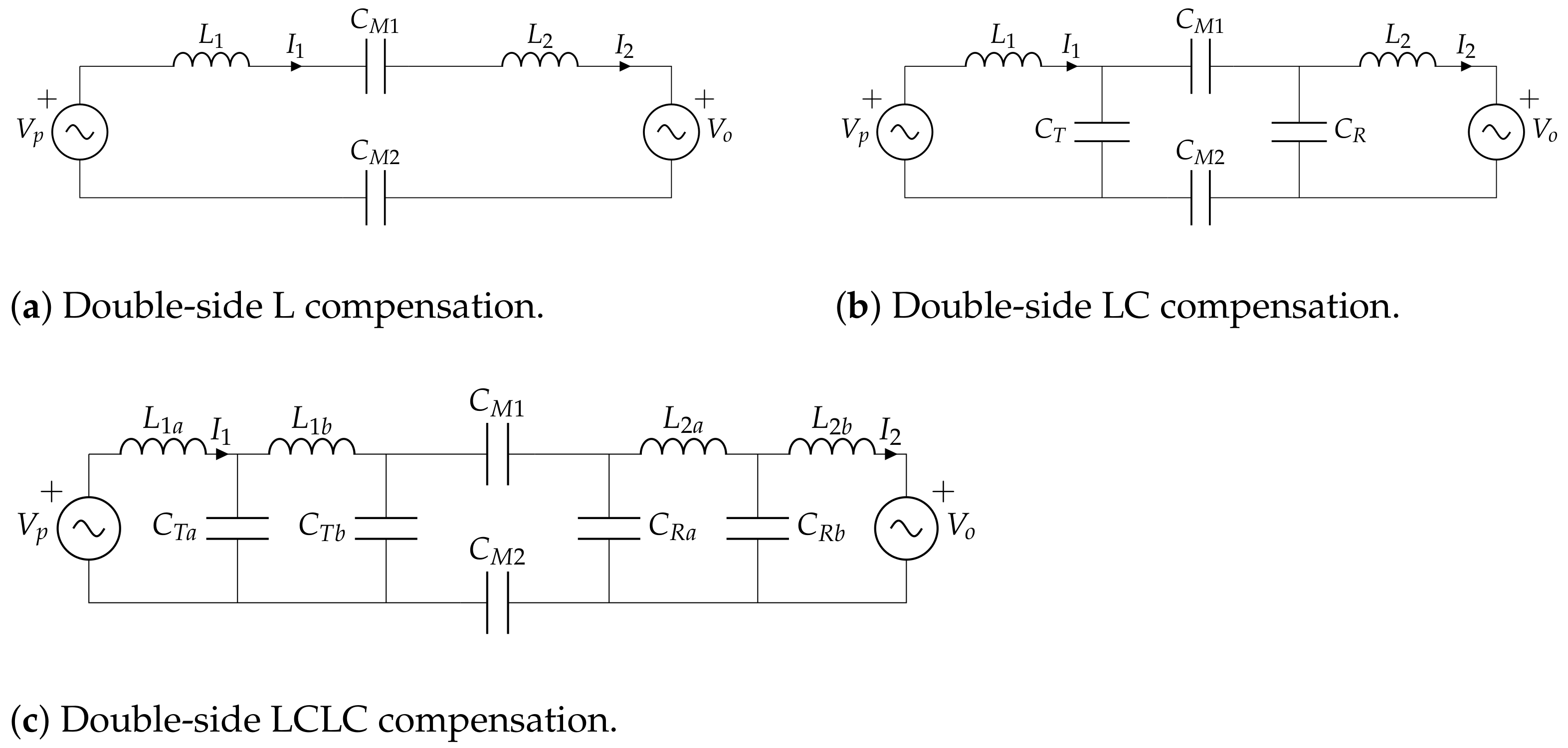
3.2. Capacitive WPT
- Restricted electric field to the zone comprising the plates. This particularity eases the role of preserving the electromagnetic emissions in potentially dangerous areas.
- Reduced size and cost when compared with resonant wireless charger. Resonant chargers rely on expensive coils made of Litz wire in order to reduce the losses at high-frequencies. However, capacitive wireless chargers just require aluminum plates. This is cost-efficient material, with good conductivity and low weight.
- Difficulty to build the bulky capacitors due to the small area available underneath the vehicle chassis, specially for light-duty vehicles such as bicycles or scooters.
- Parasitic capacitances are common in the vehicle, which may affect in the performance of the wireless charger [61].
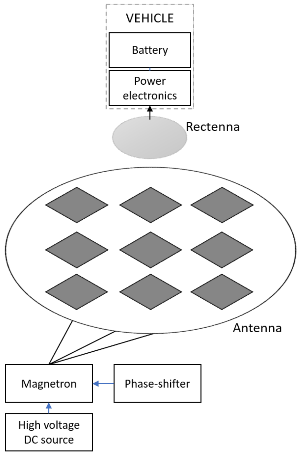
3.3. Microwave Power Transfer
- The transmitter and the receiver are designed to work in only one power flow direction. The adaptation of these chargers for V2G operations requires the replication of a dual system in the MPT.
- For high power levels, it requires bulky antennas which may avoid its applicability in some scenarios.
- The efficiency of MPT is lower than the one obtained by inductive or capacitive coupling [21]. This term is usually referred to as the beam collection efficiency.
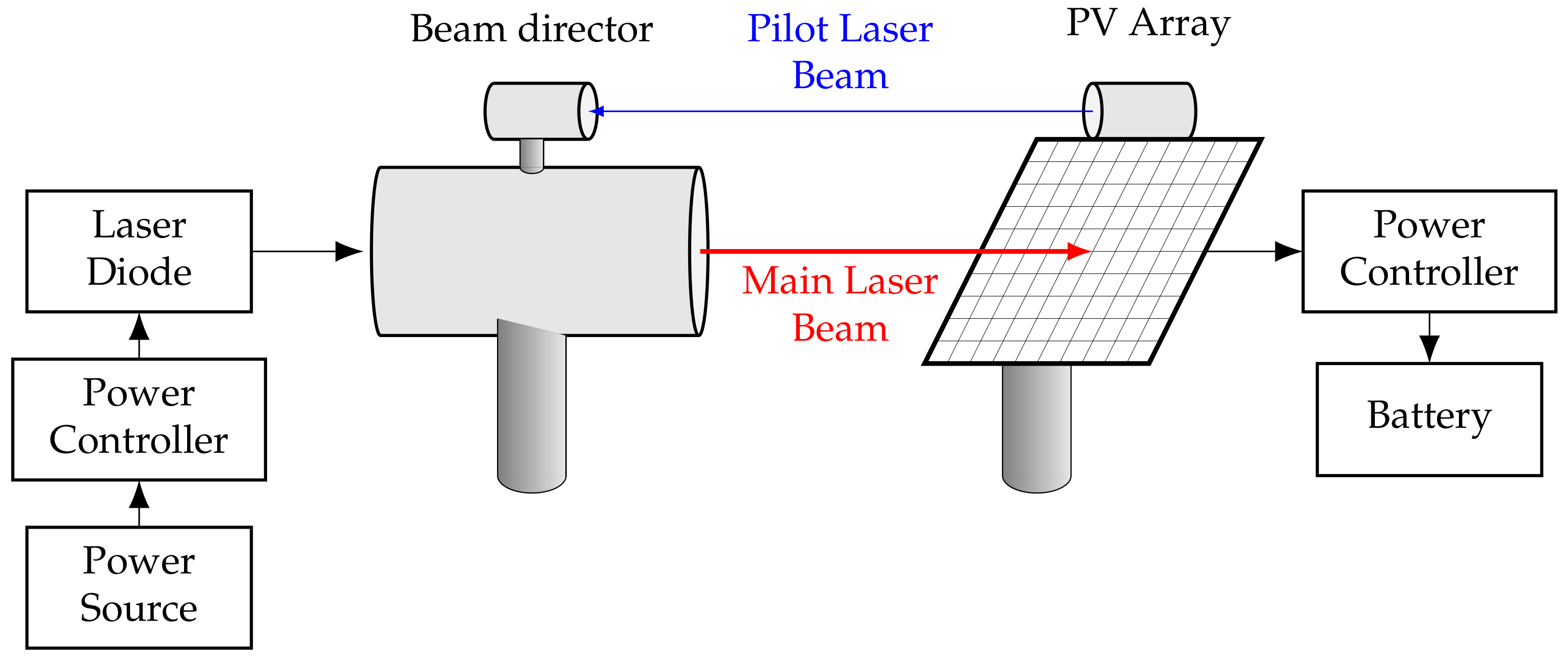
3.4. Optical WPT
- Low efficiency. As previously explained, these systems suffer rom from a poor efficiency (<25%) [91]. The advances on laser technology and photovoltaic cells could increase this metric in the near future.
- Low power levels due to the potential risks of reaching a human being.
- Difficulty to orientate the laser beam via a software control, being the passive elements (e.g., lens or mirrors) the current devices to perform this task. It is worth noting that the orientation of the laser is usually a strong requirement as the beam must be oriented to the area where no human beings are in the path between the power source and the receiver.
- Unidirectional power flow. Due to the specific and different components that are present in the transmitter and in the receiver, V2G operations are not possible with this technology.
3.5. Comparison
3.6. Safety Issues
- Ultraviolet radiation, with a wavelength comprised between 200 and 400 nm.
- Visible light, with a wavelength in the interval from 100 to 400 nm.
- Infrared Radiation, in which the wavelength is greater than 400 nm but lower than 780 nm.
- Radiofrequency, in which the frequency is in the interval from 100 kHz to 300 GHz.
- Low frequency, for waves in the range from 1 Hz to 100 kHz.
- Static electric and magnetic fields with 0 Hz of frequency.
4. Additional Technologies for EVs Wireless Charge
5. Conclusions
Author Contributions
Funding
Institutional Review Board Statement
Informed Consent Statement
Data Availability Statement
Conflicts of Interest
References
- United States Environmental Protection Agency. Fast Facts on Transportation Greenhouse Gas Emissions|Green Vehicle Guide|US EPA. 2020. Available online: https://www.epa.gov/greenvehicles/fast-facts-transportation-greenhouse-gas-emissions (accessed on 13 January 2021).
- EUROSTAT. Trends in Greenhouse Gas Emissions; Technical Report; EUROSTAT: Luxembourg, 2020. [Google Scholar]
- Vasilj, J.; Jakus, D.; Sarajcev, P. Virtual Storage-Based Model for Estimation of Economic Benefits of Electric Vehicles in Renewable Portfolios. Energies 2020, 13, 2315. [Google Scholar] [CrossRef]
- Sovacool, B.K.; Kester, J.; Noel, L.; Zarazua de Rubens, G. Actors, business models, and innovation activity systems for vehicle-to-grid (V2G) technology: A comprehensive review. Renew. Sustain. Energy Rev. 2020, 131, 109963. [Google Scholar] [CrossRef]
- Statharas, S.; Moysoglou, Y.; Siskos, P.; Zazias, G.; Capros, P. Factors Influencing Electric Vehicle Penetration in the EU by 2030: A Model-Based Policy Assessment. Energies 2019, 12, 2739. [Google Scholar] [CrossRef]
- Bui, V.T.; Dow, C.R.; Huang, Y.C.; Liu, P.; Thai, V.D. A Canopen-Based Gateway and Energy Monitoring System for Electric Bicycles. Energies 2020, 13, 3766. [Google Scholar] [CrossRef]
- Electric Vehicle Conductive Charging System—Part 1: General Requirements; International Standard IEC 61851-1:2017; International Electrotechnical Commission: Geneva, Switzerland, 2017.
- Wei, Z.; Zhao, J.; Xiong, R.; Dong, G.; Pou, J.; Tseng, K.J. Online estimation of power capacity with noise effect attenuation for lithium-ion battery. IEEE Trans. Ind. Electron. 2019, 66, 5724–5735. [Google Scholar] [CrossRef]
- Keil, P.; Jossen, A. Charging protocols for lithium-ion batteries and their impact on cycle life-An experimental study with different 18650 high-power cells. J. Energy Storage 2016, 6, 125–141. [Google Scholar] [CrossRef]
- Gonzalez-Gonzalez, J.M.; Martin, S.; Lopez, P.; Aguado, J.A. Hybrid battery-ultracapacitor storage system sizing for renewable energy network integration. IET Renew. Power Gener. 2020, 14, 2367–2375. [Google Scholar] [CrossRef]
- Trivinño-Cabrera, A.; González-González, J.M.; Aguado, J.A.J.A. Wireless Power Transfer for Electric Vehicles: Foundations and Design Approach; Springer: Cham, Switzerland, 2020; p. 175. [Google Scholar]
- Nissan. Wireless Charging System | NISSAN | TECHNOLOGICAL DEVELOPMENT ACTIVITIES. Available online: https://www.nissan-global.com/EN/TECHNOLOGY/OVERVIEW/wcs.html (accessed on 1 February 2021).
- Daymak. Daymak Launches New Special Edition EC1 Featuring Built in Wireless Charging Technology; Plans to Roll Out This Technology on Certain E-Bike Models. Available online: https://www.prnewswire.com/news-releases/daymak-launches-new-special-edition-ec1-featuring-built-in-wireless-charging-technology-plans-to-roll-out-this-technology-on-certain-e-bike-models-300464874.html (accessed on 23 January 2021).
- Luo, B.; Long, T.; Guo, L.; Dai, R.; Mai, R.; He, Z. Analysis and Design of Inductive and Capacitive Hybrid Wireless Power Transfer System for Railway Application. IEEE Trans. Ind. Appl. 2020, 56, 3034–3042. [Google Scholar] [CrossRef]
- Paglialunga, E.; Marconcini, P.; MacUcci, M. Wireless Charging of Batteries for Electric Boats. In Proceedings of the 5th International Forum on Research and Technologies for Society and Industry: Innovation to Shape the Future, RTSI, Florence, Italy, 9–12 September 2019; Institute of Electrical and Electronics Engineers Inc.: New York City, NY, USA, 2019; pp. 325–330. [Google Scholar]
- KingMeter. Wireless Charging. Available online: http://www.king-meter.com/#/product/17 (accessed on 26 January 2021).
- Beh, H.Z.Z.; Covic, G.A.; Boys, J.T. Investigation of magnetic couplers in bicycle kickstands for wireless charging of electric bicycles. IEEE J. Emerg. Sel. Top. Power Electron. 2015, 3, 87–100. [Google Scholar] [CrossRef]
- Jin, K.; Zhou, W. Wireless Laser Power Transmission: A Review of Recent Progress. IEEE Trans. Power Electron. 2019, 34, 3842–3859. [Google Scholar] [CrossRef]
- Meet Plugless|The Wireless EV Charging Station. Available online: https://www.pluglesspower.com (accessed on 1 February 2021).
- Dai, J.; Ludois, D.C. A Survey of Wireless Power Transfer and a Critical Comparison of Inductive and Capacitive Coupling for Small Gap Applications. IEEE Trans. Power Electron. 2015, 30, 6017–6029. [Google Scholar] [CrossRef]
- Shinohara, N.; Kubo, Y.; Tonomura, H. Wireless charging for electric vehicle with microwaves. In Proceedings of the 2013 3rd International Electric Drives Production Conference, Nuremberg, Germany, 29–30 October 2013; IEEE Computer Society: Washington, DC, USA, 2013. [Google Scholar]
- WiTricity: Powering Life, Wirelessly. Available online: https://witricity.com (accessed on 29 January 2021).
- Bombardier Primove to Provide Wireless Charging and Battery Technology to Berlin—Bombardier. Available online: https://www.bombardier.com/en/media/newsList/details.bombardier-transportation20150318ebusberlinabsommerfaehrtdielini.bombardiercom.html?filter-bu=tran (accessed on 2 February 2021).
- Bludszuweit, H. Project Victoria—The first spanish showcase for DWPT. In Proceedings of the FABRIC conference (Presentation), Brussels, Belgium, 2 February 2016. [Google Scholar]
- Mi, C.C.; Buja, G.; Choi, S.Y.; Rim, C.T. Modern Advances in Wireless Power Transfer Systems for Roadway Powered Electric Vehicles. IEEE Trans. Ind. Electron. 2016, 63, 6533–6545. [Google Scholar] [CrossRef]
- IEA. Global EV Outlook 2018; Technical Report; IEA: Paris, France, 2020. [Google Scholar]
- Foote, A.; Onar, O.C. A review of high-power wireless power transfer. In Proceedings of the 2017 IEEE Transportation and Electrification Conference and Expo, ITEC 2017, Chicago, IL, USA, 22–24 June 2017; Institute of Electrical and Electronics Engineers Inc.: New York City, NY, USA, 2017; pp. 234–240. [Google Scholar]
- FastinCharge: Innovative Fast Inductive Charging Solution for Electric Vehicles. Available online: https://cordis.europa.eu/project/id/314284/reporting/es (accessed on 1 February 2021).
- Eltis. Wireless Charging for Quiet and Clean Public Transport in Torino (Italy). Available online: https://www.eltis.org/discover/case-studies/wireless-charging-quiet-and-clean-public-transport-torino-italy (accessed on 22 January 2021).
- Final Report Summary—UNPLUGGED (Wireless Charging for Electic Vehicles)|Report Summary|UNPLUGGED|FP7|CORDIS| European Commission. Available online: https://cordis.europa.eu/project/id/314126/reporting/es (accessed on 25 January 2021).
- Fabric. Fabric EU Project. Available online: http://www.fabric-project.eu/www.fabric-project.eu/index.html (accessed on 1 February 2021).
- Smartroad Gotland. Available online: https://www.smartroadgotland.com (accessed on 1 February 2021).
- Nguyen, D.H. Electric vehicle—Wireless charging-discharging lane decentralized peer-to-peer energy trading. IEEE Access 2020, 8, 179616–179625. [Google Scholar] [CrossRef]
- Triviño-Cabrera, A.; Aguado, J.; González, J. Analytical characterisation of magnetic field generated by ICPT wireless charger. Electron. Lett. 2017, 53, 871–873. [Google Scholar] [CrossRef]
- Boys, J.T.; Covic, G.A. The Inductive Power Transfer Story at the University of Auckland. IEEE Circuits Syst. Mag. 2015, 15, 6–27. [Google Scholar] [CrossRef]
- Mohammad, M.; Choi, S.; Elbuluk, M.E. Loss Minimization Design of Ferrite Core in a DD-Coil-Based High-Power Wireless Charging System for Electrical Vehicle Application. IEEE Trans. Transp. Electrif. 2019, 5, 957–967. [Google Scholar] [CrossRef]
- Panchal, C.; Stegen, S.; Lu, J. Review of static and dynamic wireless electric vehicle charging system. Eng. Sci. Technol. Int. J. 2018, 21, 922–937. [Google Scholar] [CrossRef]
- Wojda, R.; Kazimierczuk, M. Winding resistance of litz-wire and multi-strand inductors. IET Power Electron. 2012, 5, 257. [Google Scholar] [CrossRef]
- Wang, C.S.; Covic, G.A.; Stielau, O.H. Investigating an LCL load resonant inverter for inductive power transfer applications. IEEE Trans. Power Electron. 2004, 19, 995–1002. [Google Scholar] [CrossRef]
- Hao, H.; Covic, G.A.; Boys, J.T. An approximate dynamic model of LCL-T-based inductive power transfer power supplies. IEEE Trans. Power Electron. 2014, 29, 5554–5567. [Google Scholar] [CrossRef]
- Keeling, N.A.; Covic, G.A.; Boys, J.T. A unity-power-factor IPT pickup for high-power applications. IEEE Trans. Ind. Electron. 2010, 57, 744–751. [Google Scholar] [CrossRef]
- Madawala, U.K.; Thrimawithana, D.J. A bidirectional inductive power interface for electric vehicles in V2G systems. IEEE Trans. Ind. Electron. 2011, 58, 4789–4796. [Google Scholar] [CrossRef]
- Villa Gazulla, J.L. Sistemas de Transferencia de Energía Para Vehículos Eléctricos Mediante Acoplamiento Inductivo—Repositorio Institucional de Documentos. Ph.D. Thesis, Universidad de Zaragoza, Zaragoza, Spain, 2009. [Google Scholar]
- Wireless Power Transfer for Light-Duty Plug-In/Electric Vehicles and Alignment Methodology; International Standard SAE J2954 202010; SAE International: Warrendale, PA, USA, 2020.
- Hazra, S.; De, A.; Cheng, L.; Palmour, J.; Schupbach, M.; Hull, B.A.; Allen, S.; Bhattacharya, S. High Switching Performance of 1700-V, 50-A SiC Power MOSFET over Si IGBT/BiMOSFET for Advanced Power Conversion Applications. IEEE Trans. Power Electron. 2016, 31, 4742–4754. [Google Scholar]
- González-González, J.; Triviño-Cabrera, A.; Aguado, J.; González-González, J.M.; Triviño-Cabrera, A.; Aguado, J.A. Design and Validation of a Control Algorithm for a SAE J2954-Compliant Wireless Charger to Guarantee the Operational Electrical Constraints. Energies 2018, 11, 604. [Google Scholar] [CrossRef]
- Triviño-Cabrera, A.; Ochoa, M.; Fernández, D.; Aguado, J.A. Independent primary-side controller applied to wireless chargers for electric vehicles. In Proceedings of the 2014 IEEE International Electric Vehicle Conference, IEVC 2014, Florence, Italy, 17–19 December 2014; Institute of Electrical and Electronics Engineers Inc.: New York City, NY, USA, 2014. [Google Scholar]
- Thrimawithana, D.J.; Madawala, U.K. A primary side controller for inductive power transfer systems. In Proceedings of the IEEE International Conference on Industrial Technology, Via del Mar, Chile, 14–17 March 2010; pp. 661–666. [Google Scholar]
- Miller, J.M.; Onar, O.C.; Chinthavali, M. Primary-side power flow control of wireless power transfer for electric vehicle charging. IEEE J. Emerg. Sel. Top. Power Electron. 2015, 3, 147–162. [Google Scholar] [CrossRef]
- Omori, H.; Iga, Y.; Morizane, T.; Kimura, N.; Nakagawa, K.; Nakaoka, M. A novel wireless EV charger using SiC single-ended quasi-resonant inverter for home use. In Proceedings of the 15th International Power Electronics and Motion Control Conference and Exposition, EPE-PEMC 2012 ECCE Europe, Novi Sad, Serbia, 4–6 September 2012. [Google Scholar]
- Deng, Q.; Wang, Z.; Chen, C.; Czarkowski, D.; Kazimierczuk, M.K.; Zhou, H.; Hu, W. Modeling and control of inductive power transfer system supplied by multiphase phase-controlled inverter. IEEE Trans. Power Electron. 2019, 34, 9303–9315. [Google Scholar] [CrossRef]
- Vu, V.B.; Dahidah, M.; Pickert, V.; Phan, V.T. A High-Power Multiphase Wireless Dynamic Charging System with Low Output Power Pulsation for Electric Vehicles. IEEE J. Emerg. Sel. Top. Power Electron. 2020, 8, 3592–3608. [Google Scholar] [CrossRef]
- Gonzalez-Gonzalez, J.M.M.; Trivino, A.; Aguado, J.A. Model Predictive Control to Maximize the Efficiency in EV Wireless Chargers. IEEE Trans. Ind. Electron. 2021, 1. [Google Scholar] [CrossRef]
- Wu, H.H.; Gilchrist, A.; Sealy, K.D.; Bronson, D. A high efficiency 5 kW inductive charger for EVs using dual side control. IEEE Trans. Ind. Inform. 2012, 8, 585–595. [Google Scholar] [CrossRef]
- Murliky, L.; Porto, R.W.; Brusamarello, V.J.; Rangel de Sousa, F.; Triviño-Cabrera, A. Active Tuning of Wireless Power Transfer System for compensating coil misalignment and variable load conditions. AEU Int. J. Electron. Commun. 2020, 119, 153166. [Google Scholar] [CrossRef]
- Zucca, M.; Cirimele, V.; Bruna, J.; Signorino, D.; Laporta, E.; Colussi, J.; Angel, M.; Tejedor, A.; Fissore, F.; Pogliano, U. Assessment of the Overall Efficiency in WPT Stations for Electric Vehicles. Sustainability 2021, 13, 2436. [Google Scholar] [CrossRef]
- Zhang, B.; Carlson, R.B.; Smart, J.G.; Dufek, E.J.; Liaw, B. Challenges of future high power wireless power transfer for light-duty electric vehicles—technology and risk management. eTransportation 2019, 2, 100012. [Google Scholar] [CrossRef]
- Qualcomm. Qualcomm Halo—Frequently Asked Questions. 2012. Available online: https://www.qualcomm.com/media/documents/files/wireless-charging-for-electric-vehicles-faq.pdf (accessed on 23 February 2021).
- Electric Vehicle Wireless Power Transfer (WPT) Systems—Part 3: Specific Requirements for the Magnetic Field Wireless Power Transfer Systems; Technical Specification IEC TS 61980-3:2019; International Electrotechnical Committee: Geneva, Switzerland, 2019.
- Electrically Propelled Road Vehicles—Magnetic Field Wireless Power Transfer—Safety and Interoperability Requirements; Standard ISO 19363:2020; International Organization for Standardization: Geneva, Switzerland, 2020.
- Sinha, S.; Kumar, A.; Regensburger, B.; Afridi, K.K. A New Design Approach to Mitigating the Effect of Parasitics in Capacitive Wireless Power Transfer Systems for Electric Vehicle Charging. IEEE Trans. Transp. Electrif. 2019, 5, 1040–1059. [Google Scholar] [CrossRef]
- Lu, K.; Nguang, S.K.; Ji, S.; Wei, L. Design of auto frequency tuning capacitive power transfer system based on class-E2 dc/dc converter. IET Power Electron. 2017, 10, 1588–1595. [Google Scholar] [CrossRef]
- Zhang, H.; Lu, F.; Hofmann, H.; Liu, W.; Mi, C.C. A Four-Plate Compact Capacitive Coupler Design and LCL-Compensated Topology for Capacitive Power Transfer in Electric Vehicle Charging Application. IEEE Trans. Power Electron. 2016, 31, 8541–8551. [Google Scholar]
- Zhang, H.; Lu, F.; Hofmann, H.; Liu, W.; Mi, C.C. Six-Plate Capacitive Coupler to Reduce Electric Field Emission in Large Air-Gap Capacitive Power Transfer. IEEE Trans. Power Electron. 2018, 33, 665–675. [Google Scholar] [CrossRef]
- Vu, V.B.; Dahidah, M.; Pickert, V.; Phan, V.T. An Improved LCL-L Compensation Topology for Capacitive Power Transfer in Electric Vehicle Charging. IEEE Access 2020, 8, 27757–27768. [Google Scholar] [CrossRef]
- Dai, J.; Ludois, D.C. Capacitive Power Transfer Through a Conformal Bumper for Electric Vehicle Charging. IEEE J. Emerg. Sel. Top. Power Electron. 2016, 4, 1015–1025. [Google Scholar] [CrossRef]
- Choi, J.; Tsukiyama, D.; Tsuruda, Y.; Davila, J.M.R. High-Frequency, High-Power Resonant Inverter With eGaN FET for Wireless Power Transfer. IEEE Trans. Power Electron. 2018, 33, 1890–1896. [Google Scholar] [CrossRef]
- Li, K.; Evans, P.; Johnson, M. SiC and GaN power transistors switching energy evaluation in hard and soft switching conditions. In Proceedings of the WiPDA 2016—4th IEEE Workshop on Wide Bandgap Power Devices and Applications, Fayetteville, AR, USA, 7–9 November 2016; Institute of Electrical and Electronics Engineers Inc.: New York City, NY, USA, 2016; pp. 123–128. [Google Scholar]
- Shah, F.M.; Xiao, H.M.; Li, R.; Awais, M.; Zhou, G.; Bitew, G.T. Comparative performance evaluation of temperature dependent characteristics and power converter using GaN, SiC and Si power devices. In Proceedings of the 2018 IEEE 12th International Conference on Compatibility, Power Electronics and Power Engineering, CPE-POWERENG 2018, Doha, Qatar, 10–12 April 2018; Institute of Electrical and Electronics Engineers Inc.: New York City, NY, USA, 2018; pp. 1–7. [Google Scholar]
- Mostafa, T.; Bui, D.; Muharam, A.; Hattori, R.; Hu, A. Capacitive Power Transfer System with Reduced Voltage Stress and Sensitivity. Appl. Sci. 2018, 8, 1131. [Google Scholar] [CrossRef]
- Yusop, Y.; Saat, S.; Husin, H.; Nguang, S.K.; Hindustan, I. Analysis of Class-E LC Capacitive Power Transfer System. Energy Procedia 2016, 100, 287–290. [Google Scholar] [CrossRef]
- Luo, B.; Mai, R.; Shi, R.; He, Z. Analysis and designed of three-phase capacitive coupled wireless power transfer for high power charging system. In Proceedings of the IEEE Applied Power Electronics Conference and Exposition—APEC, San Antonio, TX, USA, 4–8 March 2018; Institute of Electrical and Electronics Engineers Inc.: New York City, NY, USA, 2018; Volume 2018, pp. 1369–1374. [Google Scholar]
- Lu, F.; Zhang, H.; Hofmann, H.; Mi, C. A Double-Sided LCLC-Compensated Capacitive Power Transfer System for Electric Vehicle Charging. IEEE Trans. Power Electron. 2015, 30, 6011–6014. [Google Scholar] [CrossRef]
- Vincent, D.; Huynh, P.S.; Azeez, N.A.; Patnaik, L.; Williamson, S.S. Evolution of Hybrid Inductive and Capacitive AC Links for Wireless EV Charging—A Comparative Overview. IEEE Trans. Transp. Electrif. 2019, 5, 1060–1077. [Google Scholar] [CrossRef]
- Murata Manufacturing, Co. Ltd. Capacitive Coupling Wireless Power Transmission System. 2011. Available online: https://corporate.murata.com/en-eu/about/newsroom/techmag/metamorphosis16/productsmarket/wireless?intcid5=com_xxx_xxx_cmn_hd_xxx (accessed on 24 February 2021).
- Solace Power. Intelligent Wireless Power, Sense & Data Solutions. Available online: https://www.solace.ca/technology (accessed on 24 February 2021).
- Li, X.; Zhou, J.Z.; Zhang, Y.Q. Performance of Planar Arrays for Microwave Power Transmission with Phase Shifter Errors. In Proceedings of the 2015 Fith Asia International Symposium on Mechatronics, Guilin, China, 7–10 October 2015; Fifth Asia International Symposium on Mechatronics (AISM 2015) Technology, IET Conference Publications: Stevenage, UK, 2015; Volume 2015. [Google Scholar]
- Hung, N.D.; Sugamuna, S.; Shimamura, K.; Mori, K. Millimeter Wave Power Transfer to an Autonomously Controlled Micro Aerial Vehicle. Trans. Jpn. Soc. Aeronaut. Space Sci. 2020, 63, 101–108. [Google Scholar]
- Powercastco. Wireless Power Products. Available online: https://www.powercastco.com (accessed on 1 February 2021).
- Cota: Real Wireless Power. Available online: https://www.ossia.com/cota (accessed on 1 February 2021).
- Energous. WattUp® Wire-Free Charging Technology. Available online: http://energous.com (accessed on 1 February 2021).
- Nakagawa, S.; Yamanaka, Y.; Ohdo, K.; Miyasaka, J.; Shimizu, H.; Nakashima, H.; Hashimoto, K.; Shinohara, N.; Mitani, T. Development of an Electric Vehicle by Microwave Power Transmission. IFAC Proc. Vol. 2010, 3, 209–214. [Google Scholar] [CrossRef]
- Shanbhag, P.; Sabarish Narayanan, B. Coir Composite Based Electronics for Microwave Charging of Electric Vehicles. Mater. Today Proc. 2020, 24, 177–183. [Google Scholar] [CrossRef]
- Sasaki, S.; Tanaka, K. Wireless power transmission technologies for solar power satellite. In Proceedings of the 2011 IEEE MTT-S International Microwave Workshop Series on Innovative Wireless Power Transmission: Technologies, Systems, and Applications, Kyoto, Japan, 12–13 May 2011; pp. 3–6. [Google Scholar]
- Nako, S.; Okuda, K.; Miyashiro, K.; Komurasaki, K.; Koizumi, H. Wireless power transfer to a microaerial vehicle with a microwave active phased array. Int. J. Antennas Propag. 2014, 2014, 374543. [Google Scholar] [CrossRef]
- Jin, Y.; Xu, J.; Wu, S.; Xu, L.; Yang, D. Enabling the Wireless Charging via Bus Network: Route Scheduling for Electric Vehicles. IEEE Trans. Intell. Transp. Syst. 2020, 22, 1827–1839. [Google Scholar] [CrossRef]
- Duncan, K.J. Laser based power transmission: Component selection and laser hazard analysis. In Proceedings of the IEEE PELS Workshop on Emerging Technologies: Wireless Power, WoW 2016, Knoxville, TN, USA, 4–6 October 2016; Institute of Electrical and Electronics Engineers Inc.: New York City, NY, USA, 2016; pp. 100–103. [Google Scholar]
- Gibbs, Y. NASA. In Dryden Fact Sheets—Beamed Laser Power; 2014. Available online: https://www.nasa.gov/centers/armstrong/news/FactSheets/FS-087-DFRC.html (accessed on 1 February 2021).
- Achtelik, M.C.; Stumpf, J.; Gurdan, D.; Doth, K.M. Design of a flexible high performance quadcopter platform breaking the MAV endurance record with laser power beaming. In Proceedings of the 2011 IEEE/RSJ International Conference on Intelligent Robots and Systems, San Francisco, CA, USA, 25–30 September 2011; Institute of Electrical and Electronics Engineers (IEEE): New York City, NY, USA, 2011; pp. 5166–5172. [Google Scholar]
- Boukoberine, M.N.; Zhou, Z.; Benbouzid, M. A critical review on unmanned aerial vehicles power supply and energy management: Solutions, strategies, and prospects. Appl. Energy 2019, 225, 113823. [Google Scholar] [CrossRef]
- Zhou, W.; Jin, K. Efficiency Evaluation of Laser Diode in Different Driving Modes for Wireless Power Transmission. IEEE Trans. Power Electron. 2015, 30, 6237–6244. [Google Scholar] [CrossRef]
- Vu, B.; Gonzalez-Gonzalez, J.M.; Pickert, V.; Dahidah, M.; Trivino, A. A hybrid charger of conductive and inductive modes for Electric Vehicles. IEEE Trans. Ind. Electron. 2020. [Google Scholar] [CrossRef]
- Mohamed, A.A.S.; Meintz, A.; Schrafel, P.; Calabro, A. Testing and Assessment of EMFs and Touch Currents From 25-kW IPT System for Medium-Duty EVs. IEEE Trans. Veh. Technol. 2019, 68, 7477–7487. [Google Scholar] [CrossRef]
- Qian, Z.; Yan, R.; Wu, J.; He, X. Full-Duplex High-Speed Simultaneous Communication Technology for Wireless EV Charging. IEEE Trans. Power Electron. 2019, 34, 9369–9373. [Google Scholar] [CrossRef]
- Kumar, M.S.; Revankar, S.T. Development scheme and key technology of an electric vehicle: An overview. Renew. Sustain. Energy Rev. 2017, 70, 1266–1285. [Google Scholar] [CrossRef]
- Chow, J.P.W.; Chung, H.S.H.; Cheng, C.S. Online regulation of receiver-side power and estimation of mutual inductance in wireless inductive link based on transmitter-side electrical information. In Proceedings of the IEEE Applied Power Electronics Conference and Exposition—APEC, Long Beach, CA, USA, 20–24 March 2016; Institute of Electrical and Electronics Engineers Inc.: New York City, NY, USA, 2016; Volume 2016, pp. 1795–1801. [Google Scholar]
- Triviño-Cabrera, A.; Lin, Z.; Aguado, J. Impact of Coil Misalignment in Data Transmission over the Inductive Link of an EV Wireless Charger. Energies 2018, 11, 538. [Google Scholar] [CrossRef]
- Tajmohammadi, M.; Mazinani, S.M.; Nikooghadam, M.; Al-Hamdawee, Z. LSPP: Lightweight and Secure Payment Protocol for Dynamic Wireless Charging of Electric Vehicles in Vehicular Cloud. IEEE Access 2019, 7, 148424–148438. [Google Scholar] [CrossRef]
- Abdollah Mirbozorgi, S.; Bahrami, H.; Sawan, M.; Gosselin, B. A smart multicoil inductively coupled array for wireless power transmission. IEEE Trans. Ind. Electron. 2014, 61, 6061–6070. [Google Scholar] [CrossRef]
- Hwang, K.; Park, J.; Kim, D.; Park, H.H.; Kwon, J.H.; Kwak, S.I.; Ahn, S. Autonomous coil alignment system using fuzzy steering control for electric vehicles with dynamic wireless charging. Math. Probl. Eng. 2015, 2015, 205285. [Google Scholar] [CrossRef]
- Jeong, S.Y.; Thai, V.X.; Park, J.H.; Rim, C.T. Self-Inductance-Based Metal Object Detection with Mistuned Resonant Circuits and Nullifying Induced Voltage for Wireless EV Chargers. IEEE Trans. Power Electron. 2019, 34, 748–758. [Google Scholar] [CrossRef]
- Pavo, J.; Badics, Z.; Bilicz, S.; Gyimothy, S. Efficient Perturbation Method for Computing Two-Port Parameter Changes Due to Foreign Objects for WPT Systems. IEEE Trans. Magn. 2018, 54, 7204604. [Google Scholar] [CrossRef]
- Janjic, A.; Velimirovic, L.; Stankovic, M.; Petrusic, A. Commercial electric vehicle fleet scheduling for secondary frequency control. Electr. Power Syst. Res. 2017, 147, 31–41. [Google Scholar] [CrossRef]
- Hoehne, C.G.; Chester, M.V. Optimizing plug-in electric vehicle and vehicle-to-grid charge scheduling to minimize carbon emissions. Energy 2016, 115, 646–657. [Google Scholar] [CrossRef]
- Tabatabaee, S.; Mortazavi, S.S.; Niknam, T. Stochastic scheduling of local distribution systems considering high penetration of plug-in electric vehicles and renewable energy sources. Energy 2017, 121, 480–490. [Google Scholar] [CrossRef]
- Triviño-Cabrera, A.; Aguado, J.A.; Torre, S.d.l. Joint routing and scheduling for electric vehicles in smart grids with V2G. Energy 2019, 175, 113–122. [Google Scholar] [CrossRef]
- Yang, C.; Lou, W.; Yao, J.; Xie, S. On Charging Scheduling Optimization for a Wirelessly Charged Electric Bus System. IEEE Trans. Intell. Transp. Syst. 2018, 19, 1814–1826. [Google Scholar] [CrossRef]
- Li, C.; Ding, T.; Liu, X.; Huang, C. An Electric Vehicle Routing Optimization Model with Hybrid Plug-In and Wireless Charging Systems. IEEE Access 2018, 6, 27569–27578. [Google Scholar] [CrossRef]


| Charging Mode | Charging Type | Maximum Current | Maximum Power | Charging Time for 50 kWh | Kilometers from a 15 min Charge 1 |
|---|---|---|---|---|---|
| Mode 1 | Slow | 16 A, AC, Single-Phase | 3.7 kW | 14 h | 5 km |
| Mode 2 | Fast | 32 A, AC, Single-Phase | 7.4 kW | 7 h | 9 km |
| 32 A, AC, Three-Phase | 22 kW | >2 h | 27 km | ||
| Mode 3 | Rapid | 62 A, AC, Three-Phase | 43 kW | >1 h | 54 km |
| Mode 4 | Ultra-Rapid | 400 A, DC | 200 kW | 15 min 2 | 250 km2 |
| Technology | Power Level | Efficiency | Bi-Directional Flow | Gap | Intermediate Objects | On the Move | Cost |
|---|---|---|---|---|---|---|---|
| Resonant | High (Up to 100 kW) | 90–95% | Yes | < 30 cm | Yes | Yes | Medium |
| Capacitive | Medium (Up to 7 kW) | 80–85% | Yes | < 30 cm | Yes | Yes | Low |
| Microwave | Low (<250 W) | 40–50% | No | up to 1 km | No | No | High |
| Laser | Low (<500 W) | 1–15% | No | up to 1 km | No | No | High |
| Public | E-Field Strength E (kV m) | Magnetic Field Strength H (A m) | Magnetic Flux Density B (T) |
|---|---|---|---|
| Occupational | 80 | ||
| General | 21 |
Publisher’s Note: MDPI stays neutral with regard to jurisdictional claims in published maps and institutional affiliations. |
© 2021 by the authors. Licensee MDPI, Basel, Switzerland. This article is an open access article distributed under the terms and conditions of the Creative Commons Attribution (CC BY) license (http://creativecommons.org/licenses/by/4.0/).
Share and Cite
Triviño, A.; González-González, J.M.; Aguado, J.A. Wireless Power Transfer Technologies Applied to Electric Vehicles: A Review. Energies 2021, 14, 1547. https://doi.org/10.3390/en14061547
Triviño A, González-González JM, Aguado JA. Wireless Power Transfer Technologies Applied to Electric Vehicles: A Review. Energies. 2021; 14(6):1547. https://doi.org/10.3390/en14061547
Chicago/Turabian StyleTriviño, Alicia, José M. González-González, and José A. Aguado. 2021. "Wireless Power Transfer Technologies Applied to Electric Vehicles: A Review" Energies 14, no. 6: 1547. https://doi.org/10.3390/en14061547
APA StyleTriviño, A., González-González, J. M., & Aguado, J. A. (2021). Wireless Power Transfer Technologies Applied to Electric Vehicles: A Review. Energies, 14(6), 1547. https://doi.org/10.3390/en14061547