Modern Small and Microcogeneration Systems—A Review


Abstract
1. Introduction
2. Stirling Engines
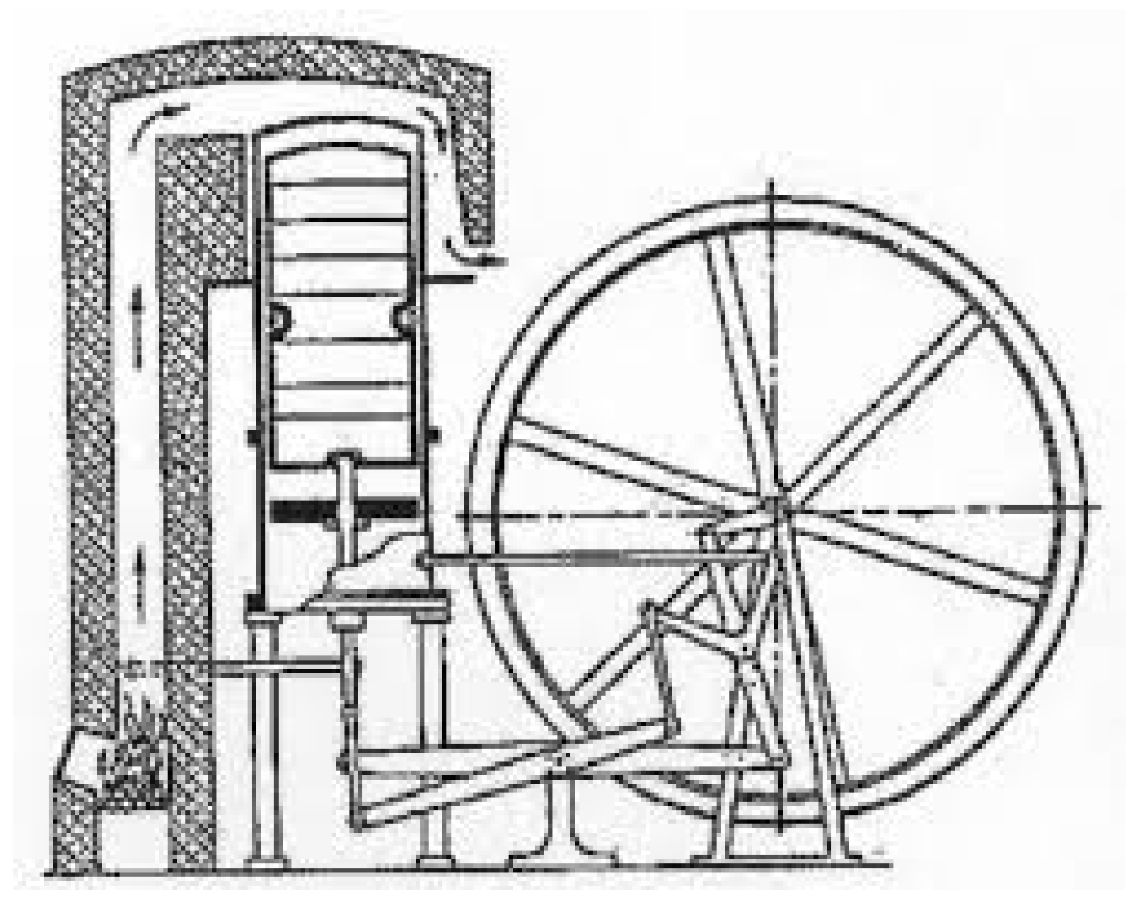
2.1. Historical Background
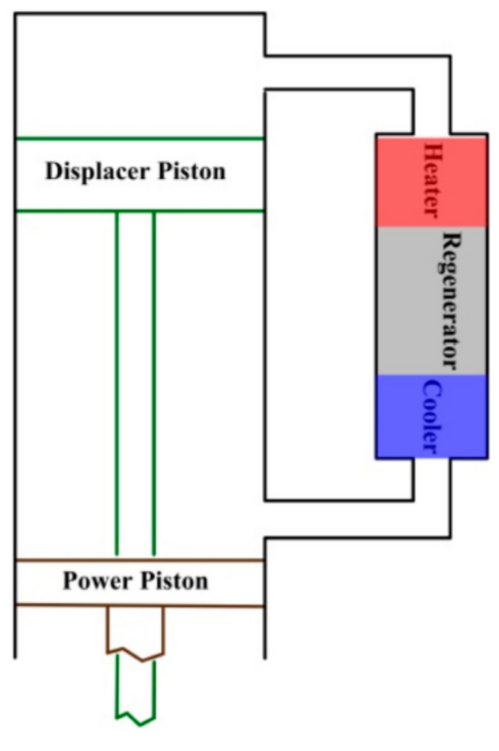
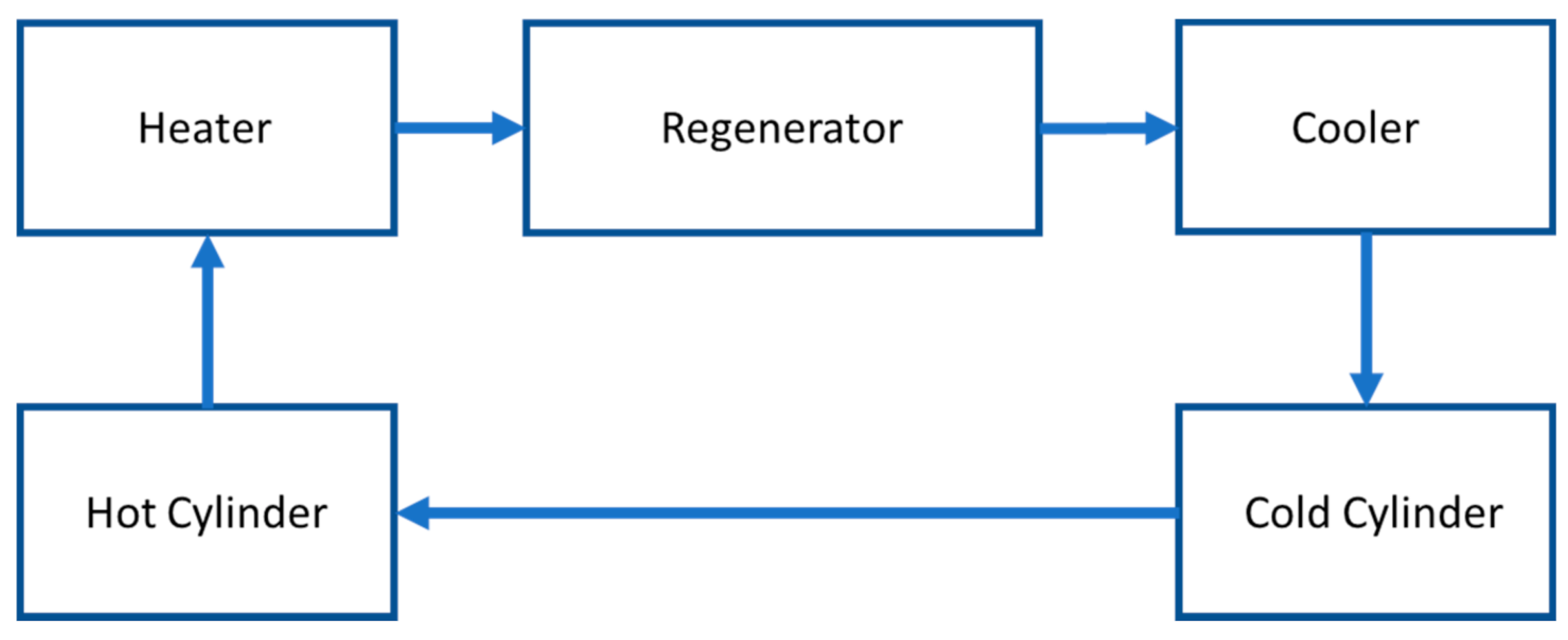
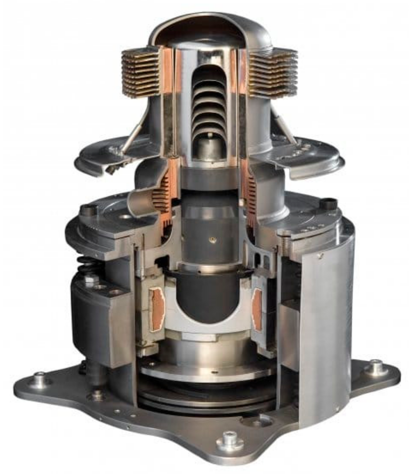
2.2. Functional Description
- heating and expansion-heat is supplied from an external source, raising the gas temperature and thus the pressure. This causes the piston to slide and provides useful work;
- flow and cooling-the piston moves to force gas into another cylinder where it is cooled. Cooling the gas allows for easier compression, meaning less work is required to proceed this process than in step 1;
- compression-the gas is compressed and the excess heat resulting from compression is removed via the cooling source;
- reverse flow and heating-the pressurized gas returns to the starting cylinder and the cycle repeats.
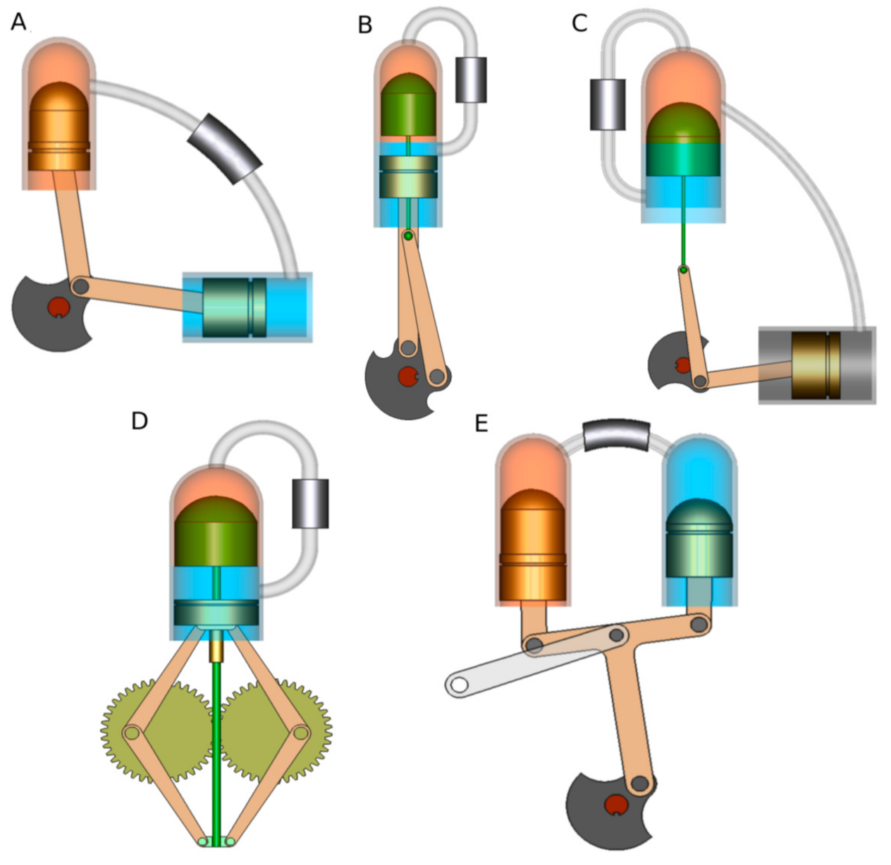
2.3. Stirling Engine Designs
2.4. Stirling Engine Applications
2.5. Summary
3. Microturbines
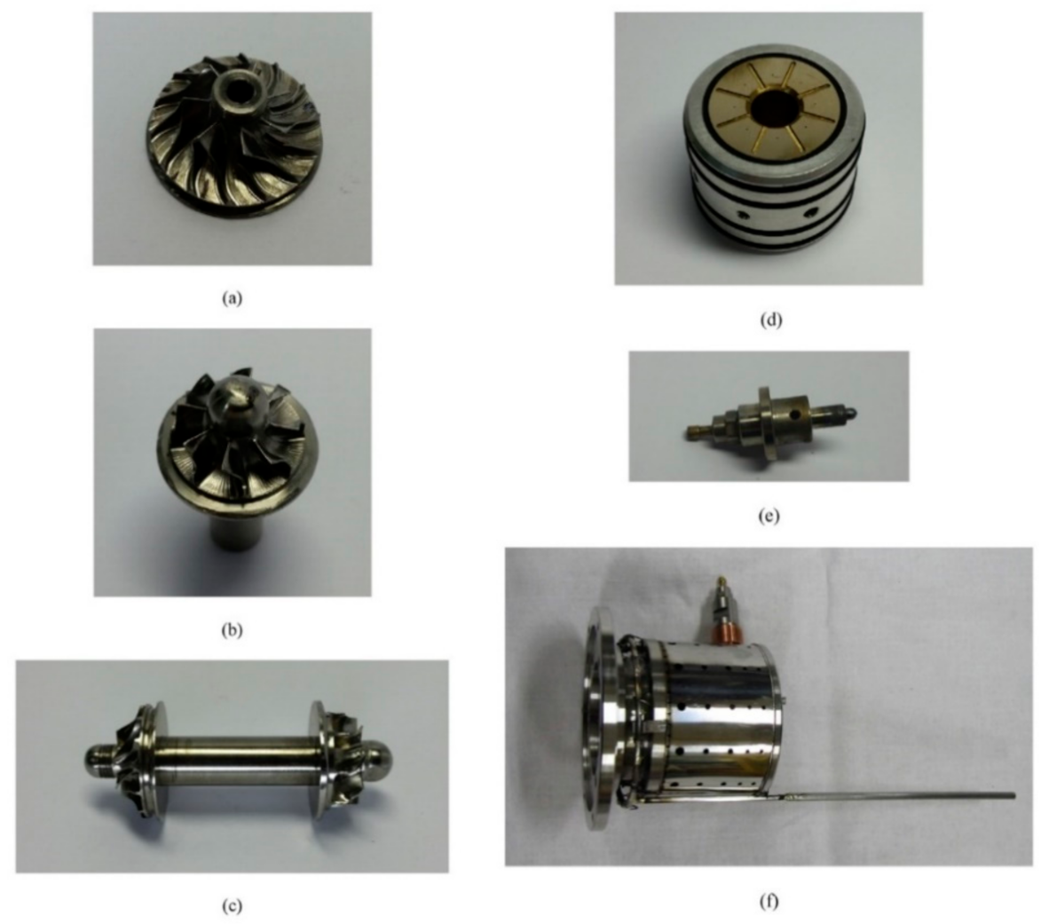
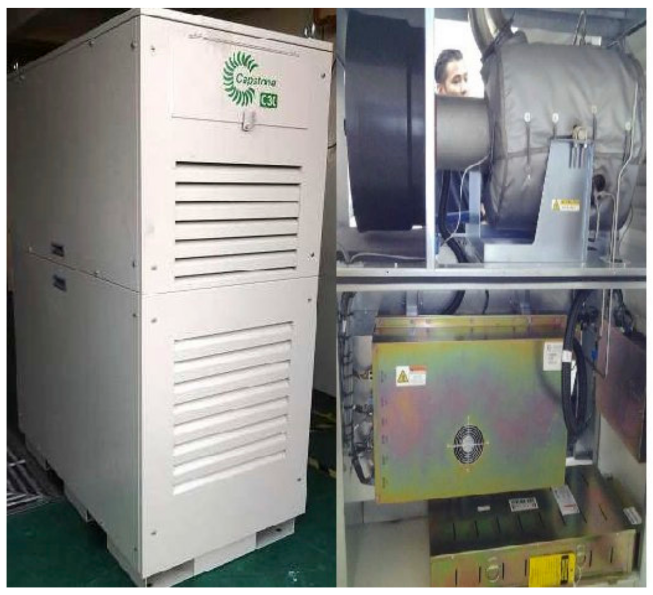
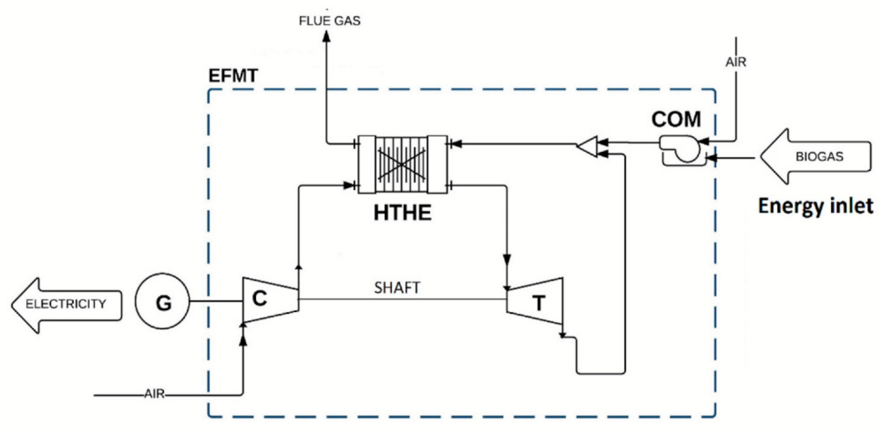
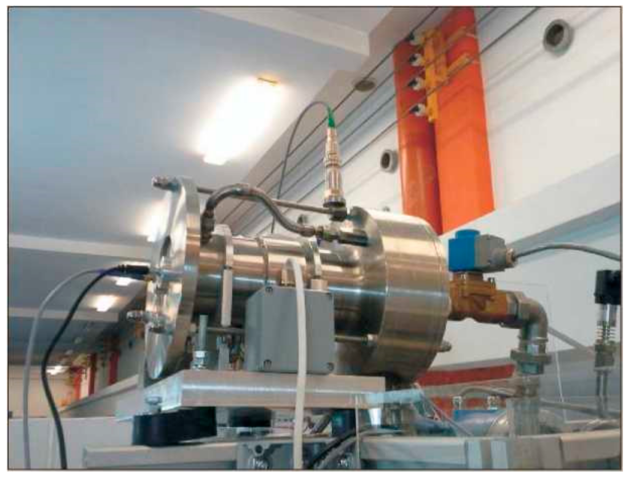
3.1. Gas Microturbines
3.2. Steam Microturbines
- live steam: pressure 12 bar, temperature 573 K;
- steam mass flow 0.075 kg/s;
- pressure in the condenser 0.25 bar;
- rotational speed 6276 rpm.
- live steam: pressure 5.8 bar, temperature 553 K (280 °C);
- steam mass flow 2 kg/s;
- 3.5 bar back pressure.
4. Volumetric Expanders (Vane, Lobe, Screw, Piston, Wankel, Gerotor)
4.1. Vane Expanders
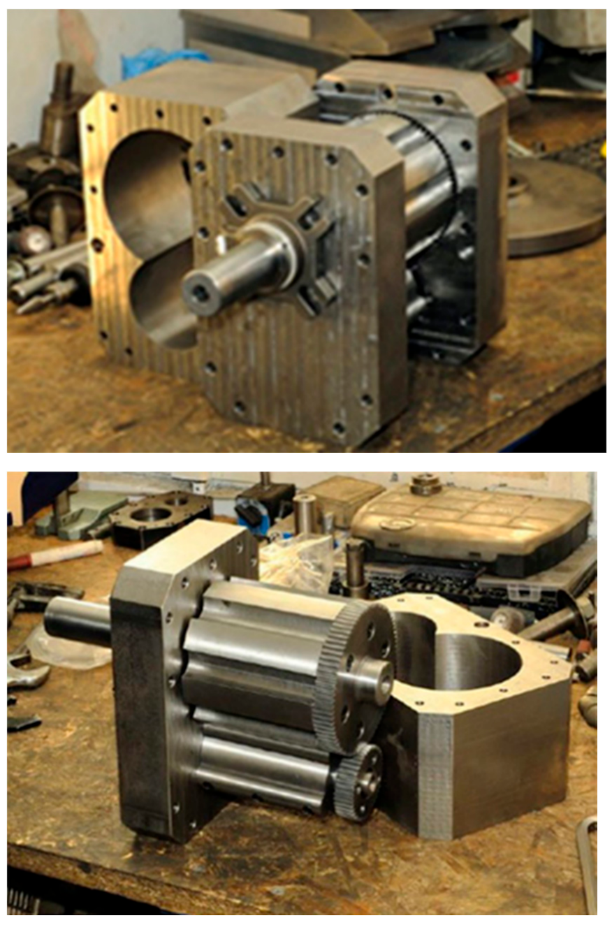
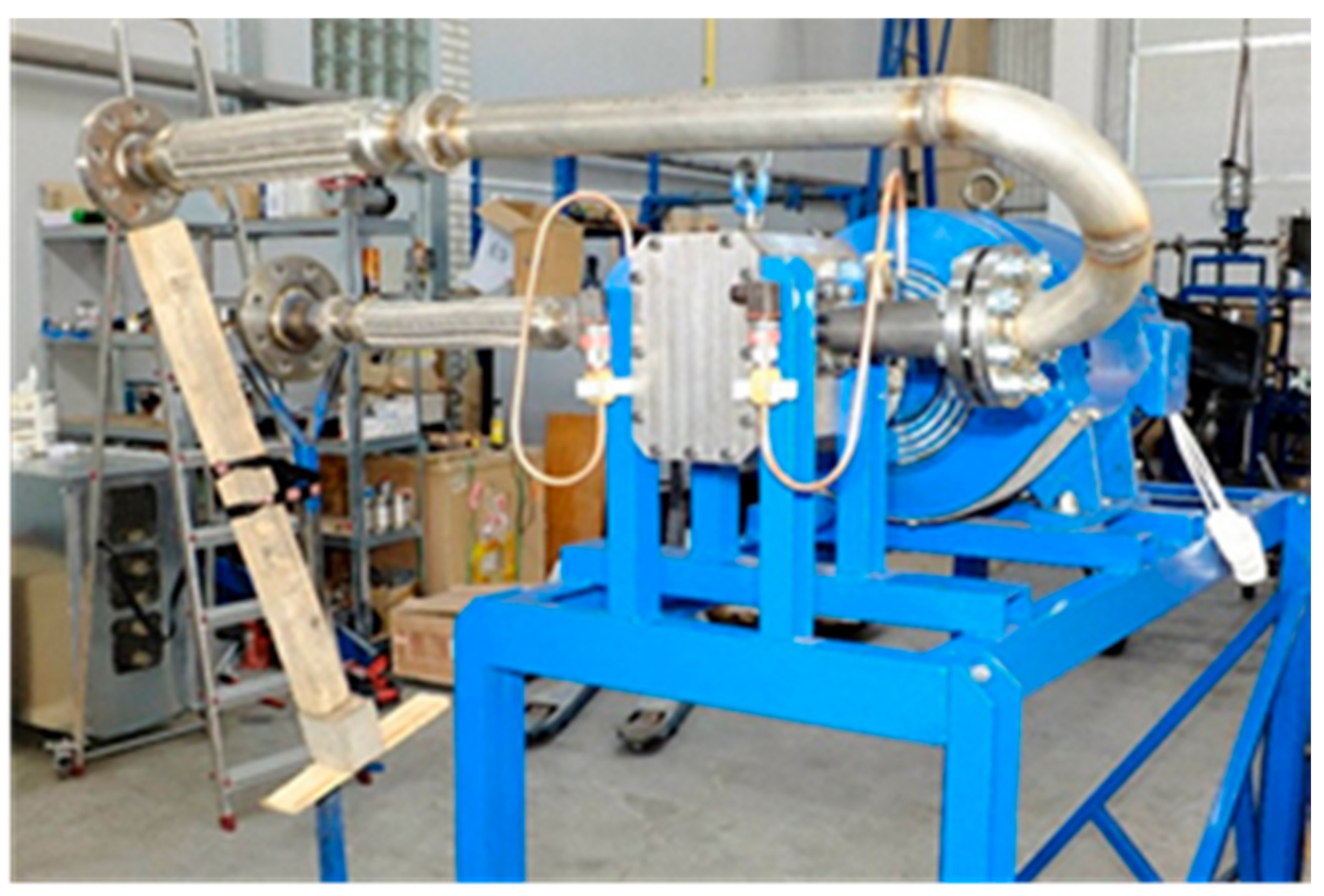
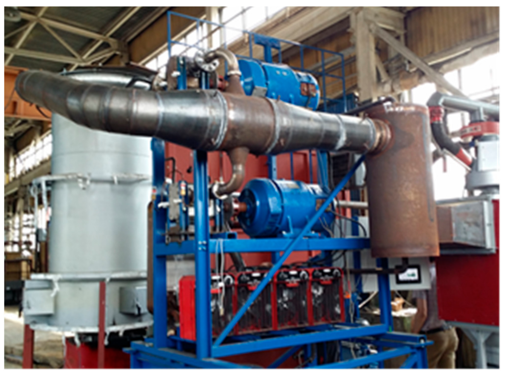
4.2. Lobe Expanders
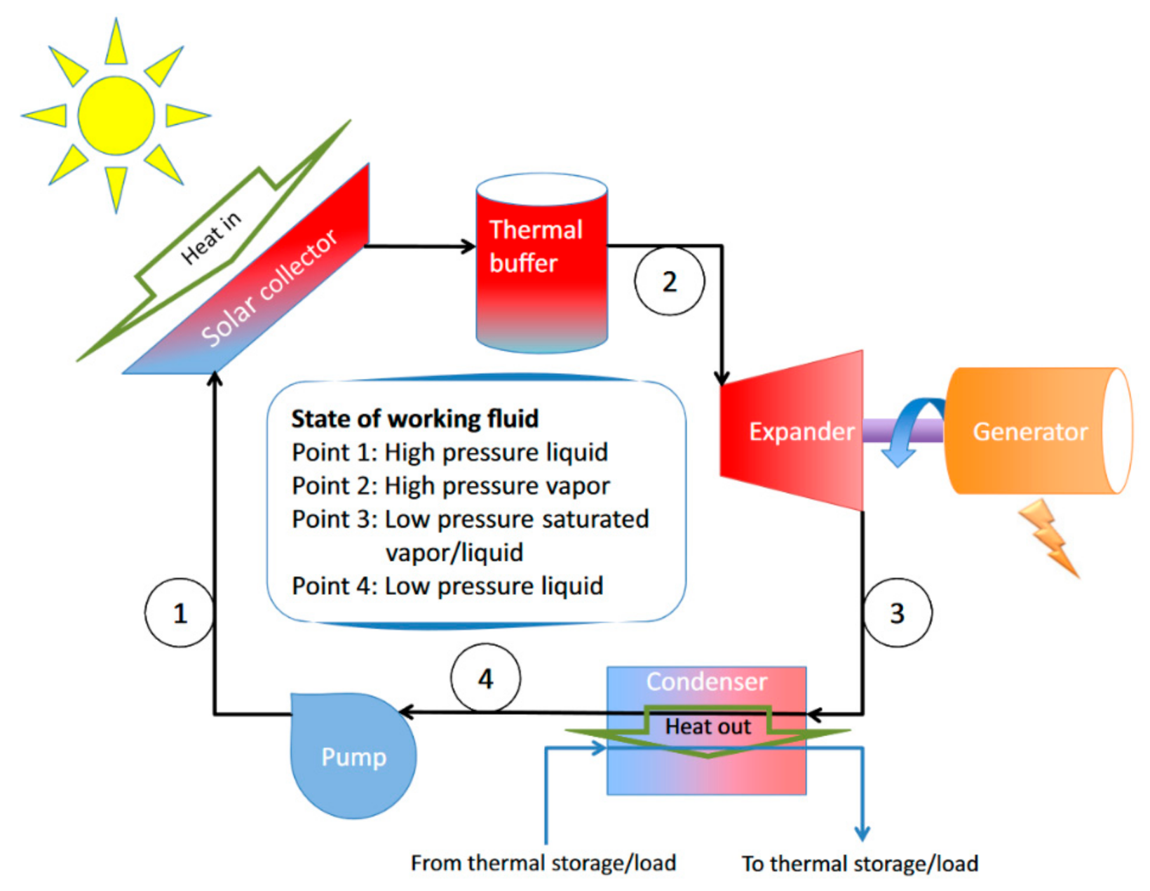
4.3. Screw Expanders
4.4. Piston Expanders
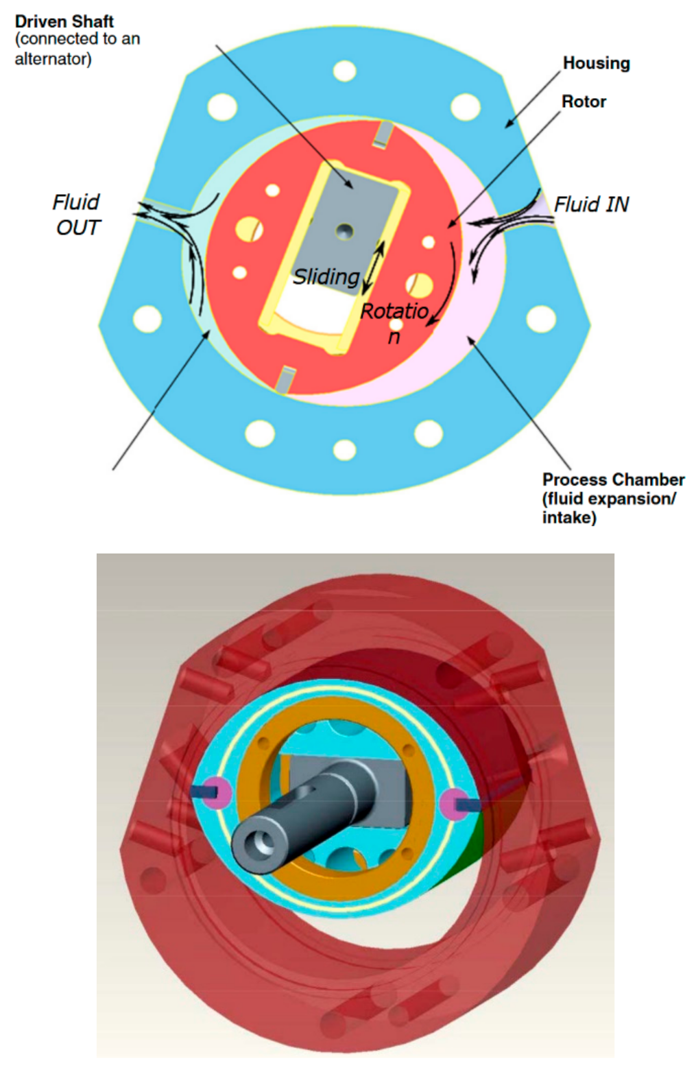
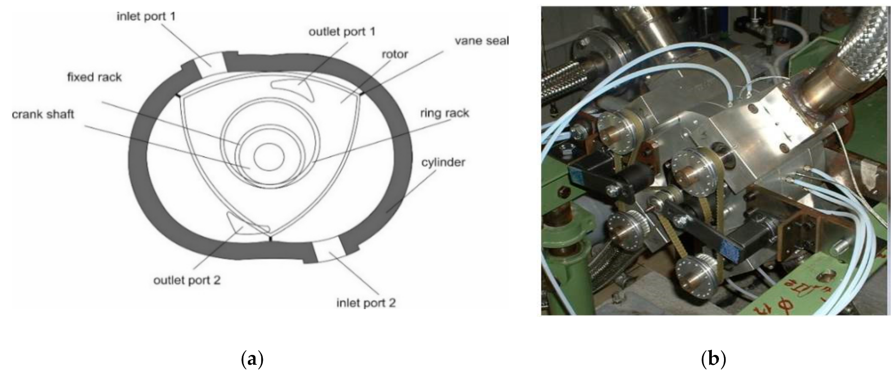
4.5. Wankel Expanders
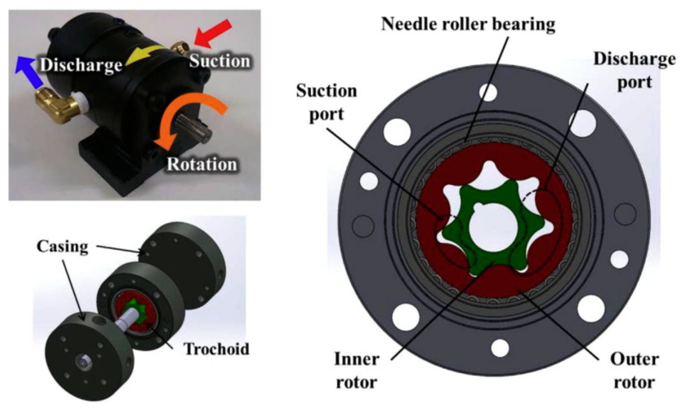
4.6. Gerotor Expanders
5. Fuel Cells
- maximization of generated electricity;
- following the instantaneous demand for electricity;
- maximization of heat production;
- following the instantaneous demand for heat;
- maximization of prosumer profits.
6. Conclusions
- Multi-vane expanders are applied in experimental test-stands of micro CHP ORC systems. The experimental tests were proceeded for working fluid absolute pressure at the inlet to the multi-vane expander ranging between 1.5 and 6.39 bar. The power output of tested multi-vane expanders was ranging between 65 W and 8 kW, rotational speed was ranging between 1200 and 4100 rpm and isentropic efficiency was ranging between 17.2 and 55.8%. Efficiency of the ORC systems was ranging between 0.75 and 7.65%.
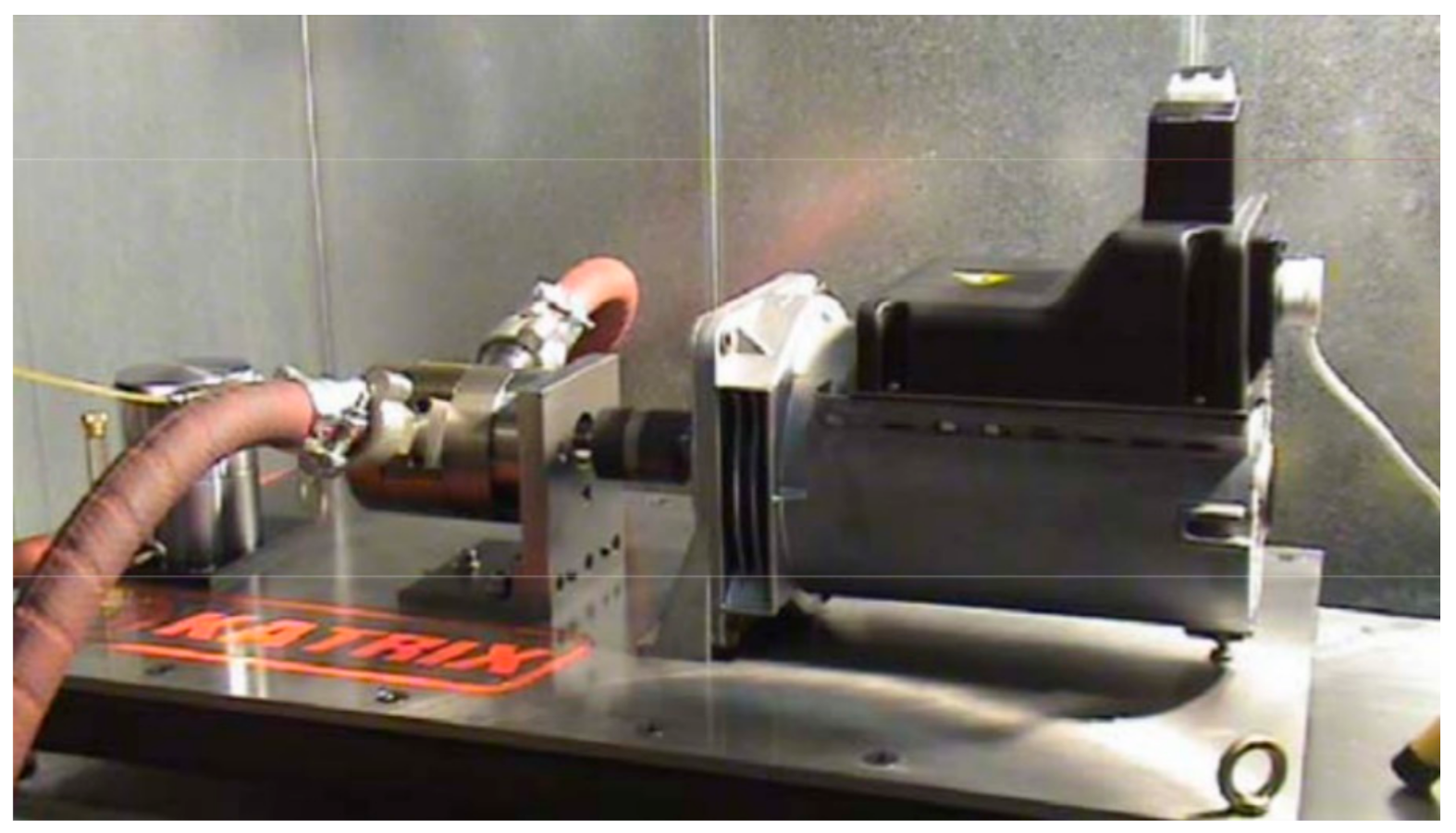
- Rotary lobe expanders are applied in experimental test-stands of small steam plants. The working fluid pressure at the inlet to the rotary lobe expander ranges between 8 and 40 bar. The working fluid pressure at the inlet should not exceed 350 °C due to sealing problems. The power output of these machines ranges from single kilowatts up to ca. 150 kW for a single stage expander. Lobe expanders were also applied in solar-powered ORCs.
- Root expanders are applied in experimental test-stands of micro CHP ORC systems. The experimental tests were proceeded for working fluid pressure at the inlet to the Roots expander ranging between 3 and 10.8 bar. The working fluid pressure at the outlet of the machine was ranging between 1.35 and 2.25 bar. The power output of tested Roots expanders was ranging between 100 W and 3 kW. The rotational speed of the expander was varying between 1500 and 11000 rpm. The highest expander isentropic efficiency of ca. 50% was obtained.
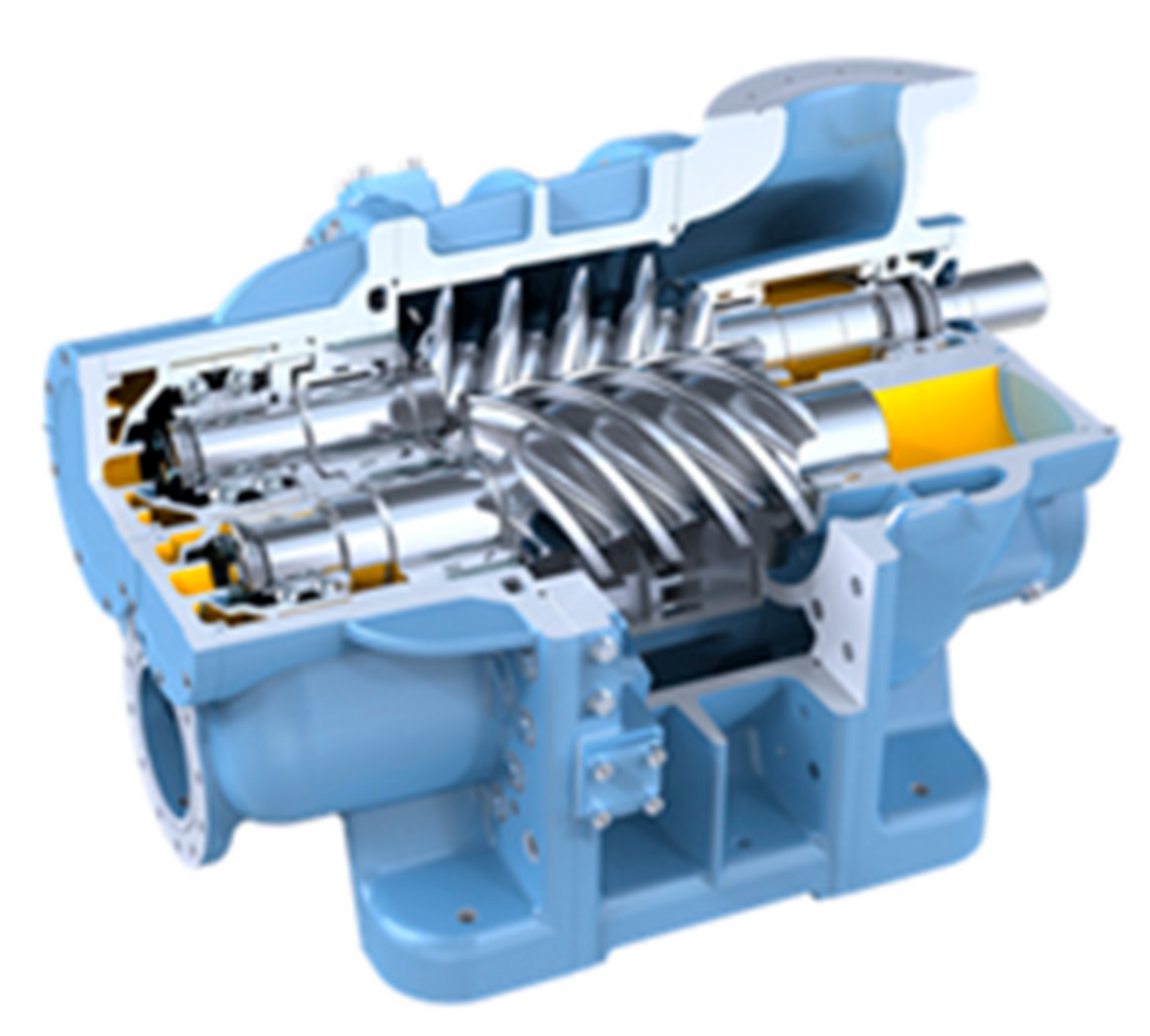
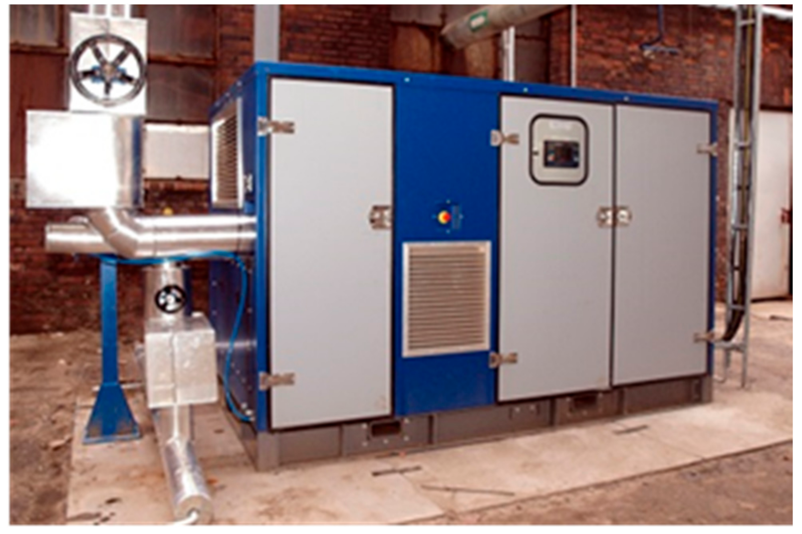
- Screw expanders are successfully applied in commercially available steam and ORC CHP systems. They can operate in different conditions. The absolute pressure of the working fluid at the inlet to the screw expander is ranging between 3 and 25 bar, while the temperature of the heat sources is ranging between 90 and 540 °C. The power output of these systems ranges between few kW and 630 kW while efficiency of the ORC systems adopting screw expanders ranges between 5 and 10%.
- Single-screw expanders are applied in experimental test-stands of small steam and ORC CHP plants. The experimental tests were proceeded for working fluid absolute pressure at the inlet to the screw expander ranging between 3 and 6.75 bar, and the temperature of the heat sources ranging between 80 and 120 °C. The power output of these expanders ranges between 5 kW and 172 kW, rotational speed ranges between 2000 and 3000 rpm, obtained efficiency of the expanders ranges between 10 and 66% while efficiency of the ORC systems adopting single-screw expanders ranges between 7.98 and 9.3%.
- Piston expanders are applied in experimental test-stands of small steam and ORC CHP plants. The experimental tests were proceeded for working fluid absolute pressure at the inlet to the piston expander ranging between 11 and 34 bar and the inlet temperature of the working fluid ranging between 65 and 340 °C. The power output of these expanders ranges between 0.25 kW and 3 kW, rotational speed ranges between 320 rpm and 4000 rpm and expanders efficiency ranges between 55 and 70%.
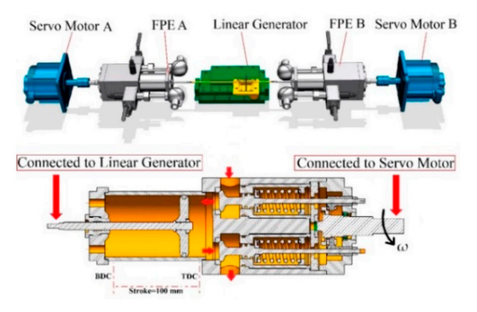
- Linear piston expanders are applied in experimental test-stands of ORC CHP plants. The experimental tests were proceeded for working fluid absolute pressure at the inlet to the linear piston expander ranging between 13 and 21 bar. The maximum power output of 22.7 W was obtained in case of these expanders, and internal efficiency was ranging between 66.2 and 93%.
- Wankel expanders are applied in experimental test-stands of steam plants. The experimental tests were proceeded for working fluid absolute pressure at the inlet to the Wankel expander ranging between 27.6 and 65 bar and the temperature of the working fluid ranging between 231–410 °C. The power output of Wankel expanders ranges between 12 and 17 kW and rotational speed ranges between 2196 and 2578 rpm.
- Gerotor expanders are applied in experimental test-stands of ORC plants. The experimental tests were proceeded for working fluid absolute pressure at the inlet to the gerotor expander ranging between 27.6 and 65 bar and the temperature of the working fluid ranging between 80 and 160 °C. The power output of Wankel expanders ranges between 0.2 and 2.07 kW, rotational speed was equal to 3000 rpm and obtained efficiency of the expanders ranges between 35 and 85%.
Author Contributions
Funding
Acknowledgments
Conflicts of Interest
References
- Capuano, D.L. Energy Information Administration; Annual Energy Outlook: Washington, DC, USA, 2020. [Google Scholar]
- Aymar, R.; Barabaschi, P.; Shimomura, Y. The ITER design. Plasma Phys. Control. Fusion 2002, 44, 519–565. [Google Scholar] [CrossRef]
- Opriş, I.; Cenuşă, V.; Norişor, M.; Darie, G.; Alexe, F.-N.; Costinaş, S. Parametric optimization of the thermodynamic cycle design for supercritical steam power plants. Energy Convers. Manag. 2020, 208, 112587. [Google Scholar] [CrossRef]
- Garievskii, M. Optimization of CCGT operating modes at variable loads taking into account equivalent operating hours. J. Phys. 2020, 1683, 042022. [Google Scholar]
- Alanne, K.; Saari, A. Distributed energy generation and sustainable development. Renew. Sustain. Energy Rev. 2006, 10, 539–558. [Google Scholar] [CrossRef]
- Wang, X.; Shu, G.; Yan, F.; Feng, W.; Wang, R.; Pan, J. Optimization of a distributed energy system with multiple waste heat sources and heat storage of different temperatures based on the energy quality. Appl. Therm. Eng. 2020, 181, 115975. [Google Scholar] [CrossRef]
- Luo, Z.; Yang, S.; Xie, N.; Xie, W.; Liu, J.; Agbodjan, Y.S.; Liu, Z. Multi–objective capacity optimization of a distributed energy system considering economy, environment and energy. Energy Convers. Manag. 2019, 200, 112081. [Google Scholar] [CrossRef]
- Lowitzsch, J.; Hoicka, C.E.; Van Tulder, F.J. Renewable energy communities under the 2019 European Clean Energy Package–Governance model for the energy clusters of the future? Renew. Sustain. Energy Rev. 2020, 122, 109489. [Google Scholar] [CrossRef]
- Rosato, A.; Sibilio, S. Performance assessment of a micro-cogeneration system under realistic operating conditions. Energy Convers. Manag. 2013, 70, 149–162. [Google Scholar] [CrossRef]
- Rosato, A.; Sibilio, S.; Ciampi, G. Energy, environmental and economic dynamic performance assessment of different micro-cogeneration systems in a residential application. Appl. Therm. Eng. 2013, 59, 599–617. [Google Scholar] [CrossRef]
- Rosato, A.; Sibilio, S. Energy performance of a micro-cogeneration device during transient and steady-state operation: Experiments and simulations. Appl. Therm. Eng. 2013, 52, 478–491. [Google Scholar] [CrossRef]
- Rosato, A.; Sibilio, S. Calibration and validation of a model for simulating thermal and electric performance of an internal combustion engine-based micro-cogeneration device. Appl. Therm. Eng. 2012, 45, 79–98. [Google Scholar] [CrossRef]
- De Paepe, M.; Mertens, D. Combined heat and power in a liberalised energy market. Energy Convers. Manag. 2007, 48, 2542–2555. [Google Scholar] [CrossRef]
- De Paepe, M.; D’Herdt, P.; Mertens, D. Micro-CHP systems for residential applications. Energy Convers. Manag. 2006, 47, 3435–3446. [Google Scholar] [CrossRef]
- Pehnt, M. Environmental impacts of distributed energy systems—The case of micro cogeneration. Environ. Sci. Policy 2008, 11, 25–37. [Google Scholar] [CrossRef]
- Pehnt, M.; Fischer, C. Environmental Impacts of Micro Cogeneration. In Micro Cogeneration; Springer Nature: Berlin/Heidelberg, Germany, 2006; pp. 87–116. [Google Scholar]
- Dowson, D. Men of Tribology: Guillaume Amontons (1663–1705) and John Theophilus Desaguliers (1683–1744). J. Lubr. Technol. 1978, 100, 2–5. [Google Scholar] [CrossRef]
- Talbot, G.R.; Pacey, A.J. Antecedents of Thermodynamics in the Work of Guillaume Amontons. Centaurus 1972, 16, 20–40. [Google Scholar] [CrossRef]
- Guillaume, A. Ciencias Químicas. Rev. CENIC 2005, 36, 187–195. [Google Scholar]
- Woerlen, I. Hot Air Engines. Available online: www.hotairengines.org (accessed on date 20 December 2020).
- Cayley, S.G.; Gordon, A.; Gurney, G.; Brunel, I.K.; Stephenson, R. Discussion. Sir George Cayley’s Hot–Air Engine. (Includes Plate). In Minutes of the Proceedings of the Institution of Civil Engineers; Thomas Telford Ltd.: London, UK, 1850; Volume 9, pp. 9197–9203. [Google Scholar]
- Gibbs-Smith, C.H. Sir George Cayley* ’Father of aerial navigation’ (1773–1857). Notes Rec. R. Soc. 1962, 17, 36–56. [Google Scholar] [CrossRef]
- Cooke, C.W. On Wenham’s Heated-Air Engine. Proc. Inst. Mech. Eng. 1873, 24, 63–86. [Google Scholar] [CrossRef]
- Stirling International. Available online: www.stirlinginternational.org (accessed on 20 December 2020).
- Harlow, H.F. Hot Air Engines. Sci. Am. 1852, 7, 293. [Google Scholar] [CrossRef]
- Zanzig, J. The Stirling Cycle Engine; SAE Technical Paper Series; SAE International: Warrendale, PA, USA, 1963. [Google Scholar]
- Otaka, T. Stirling Engines, Their History and Basic Theories. J. Inst. Electr. Eng. Jpn. 2016, 136, 596–600. [Google Scholar] [CrossRef]
- Kazmierczak, J.; Zmudzki, S. Relative Analysis of free–Piston Stirling Engine Dynamics. J. Propulsion Power 1986, 2, 505–513. [Google Scholar]
- Moscrip, W. The Moscrip–Stirling engine–A new departure. In Proceedings of the Intersociety Energy Conversion Engineering Conference, San Francisco, CA, USA, 19 August 1984. [Google Scholar]
- Szałwiński, P. Silnik Stirlinga i Możliwości Jego Zastosowania w Energetyce; European Union funded Research Grant; Wrocław University of Science and Technolgy: Wrocław, Poland, 2010. [Google Scholar]
- Walker, G. Elementary Design Guidelines for Stirling Engines. Proc. Intersoc. Energy Convers. Eng. Conf. 1979, 1, 1066–1068. [Google Scholar]
- Walker, G.C.; Senft, J.R. Free Piston Stirling Engines. Lecture Notes in Engineering; Springer Verlag: Berlin/Heidelberg, Germany, 1985; ISBN 978-3-642-82526-2. [Google Scholar]
- Karabulut, H.; Yücesu, H.S.; Koca, A. Manufacturing and testing of a V-type Stirling engine. Turkish. J. Eng. Environ. Sci. 2000, 24, 71–80. [Google Scholar]
- Yoshihara, S.; Hoshino, T. Model free piston Stirling engine. In Proceedings of the Symposium on Stirlling Cycle, Japan Society of Mechanical Engineers, Tokyo, Japan, 17–18 October 2003; pp. 87–88. [Google Scholar]
- Żmudzki, S. Silniki Stirlinga; WNT—Wydawnictwa Naukowo-Techniczne: Warsaw, Poland, 1993. [Google Scholar]
- Rahmati, A.; Varedi-Koulaei, S.M.; Ahmadi, M.H.; Ahmadi, H. Dimensional synthesis of the Stirling engine based on optimizing the output work by evolutionary algorithms. Energy Rep. 2020, 6, 1468–1486. [Google Scholar] [CrossRef]
- Thombare, D.G.; Umale, N. Theoretical Analysis of Effect of Regenerator Geometry and Material on Stirling Engine Performance. In Proceedings of the 1st National, P.G. Conference RIT NCon PG–2015, Sangli, Maharashtra, India, 1 June 2015. [Google Scholar]
- Thombare, D.G.; Karmare, S.V. Theoretical and experimental investigation of Alfa type bio mass Stirling engine with effect of regenerator effectiveness, heat transfer, and properties of working fluid. J. Renew. Sustain. Energy 2012, 4, 43126. [Google Scholar] [CrossRef]
- Karabulut, H.; Okur, M.; Halis, S.; Altin, M. Thermodynamic, dynamic and flow friction analysis of a Stirling engine with Scotch yoke piston driving mechanism. Energy 2019, 168, 169–181. [Google Scholar] [CrossRef]
- Bulinski, Z.; Szczygieł, I.; Krysiński, T.; Stanek, W.; Czarnowska, L.; Gładysz, P.; Kabaj, A. Finite time thermodynamic analysis of small alpha-type Stirling engine in non-ideal polytropic conditions for recovery of LNG cryogenic exergy. Energy 2017, 141, 2559–2571. [Google Scholar] [CrossRef]
- Kropiwnicki, J. Analysis of start energy of Stirling engine type alpha. Arch. Thermodyn. 2019, 40, 243–259. [Google Scholar] [CrossRef]
- Bataineh, K. Mathematical formulation of alpha -type Stirling engine with Ross Yoke mechanism. Energy 2018, 164, 1178–1199. [Google Scholar] [CrossRef]
- Almajri, A.K.; Mahmoud, S.; Al-Dadah, R. Modelling and parametric study of an efficient Alpha type Stirling engine performance based on 3D CFD analysis. Energy Convers. Manag. 2017, 145, 93–106. [Google Scholar] [CrossRef]
- Altin, M.; Okur, M.; Ipci, D.; Halis, S.; Karabulut, H. Thermodynamic and dynamic analysis of an alpha type Stirling engine with Scotch Yoke mechanism. Energy 2018, 148, 855–865. [Google Scholar] [CrossRef]
- Ipci, D.; Karabulut, H. Thermodynamic and dynamic analysis of an alpha type Stirling engine and numerical treatment. Energy Convers. Manag. 2018, 169, 34–44. [Google Scholar] [CrossRef]
- Bataineh, K.M. Numerical thermodynamic model of alpha-type Stirling engine. Case Stud. Therm. Eng. 2018, 12, 104–116. [Google Scholar] [CrossRef]
- Cinar, C.; Yücesu, H.S.; Topgül, T.; Okur, M. Beta-type Stirling engine operating at atmospheric pressure. Appl. Energy 2005, 81, 351–357. [Google Scholar] [CrossRef]
- Solmaz, H.; Ardebili, S.M.S.; Aksoy, F.; Calam, A.; Yılmaz, E.; Arslan, M. Optimization of the operating conditions of a beta-type rhombic drive stirling engine by using response surface method. Energy 2020, 198, 117377. [Google Scholar] [CrossRef]
- Chahartaghi, M.; Sheykhi, M. Thermal modeling of a trigeneration system based on beta-type Stirling engine for reductions of fuel consumption and pollutant emission. J. Clean. Prod. 2018, 205, 145–162. [Google Scholar] [CrossRef]
- Uchman, W.; Remiorz, L.; Grzywnowicz, K.; Kotowicz, J. Parametric analysis of a beta Stirling engine–A prime mover for distributed generation. Appl. Therm. Eng. 2018, 145, 693–704. [Google Scholar] [CrossRef]
- Shendage, D.; Kedare, S.B.; Bapat, S. An analysis of beta type Stirling engine with rhombic drive mechanism. Renew. Energy 2011, 36, 289–297. [Google Scholar] [CrossRef]
- Chahartaghi, M.; Sheykhi, M. Energy and exergy analyses of beta-type Stirling engine at different working conditions. Energy Convers. Manag. 2018, 169, 279–290. [Google Scholar] [CrossRef]
- Ahmed, F.; Huang, H.; Khan, A.M. Numerical modeling and optimization of beta-type Stirling engine. Appl. Therm. Eng. 2019, 149, 385–400. [Google Scholar] [CrossRef]
- Caetano, B.C.; Lara, I.F.; Borges, M.U.; Sandoval, O.R.; Valle, R.M. A novel methodology on beta-type Stirling engine simulation using CFD. Energy Convers. Manag. 2019, 184, 510–520. [Google Scholar] [CrossRef]
- Sowale, A.; Kolios, A.; Onabanjo, T.; Somorin, T.; Parker, A.; Williams, L.; Collins, M.; McAdam, E.; Tyrrel, S. Thermodynamic analysis of a gamma type Stirling engine in an energy recovery system. Energy Convers. Manag. 2018, 165, 528–540. [Google Scholar] [CrossRef]
- Alfarawi, S.; Al-Dadah, R.; Mahmoud, S. Enhanced thermodynamic modelling of a gamma-type Stirling engine. Appl. Therm. Eng. 2016, 106, 1380–1390. [Google Scholar] [CrossRef]
- Katooli, M.H.; Moghadam, R.A.; Hooshang, M. Investigation on effective operating variables in gamma-type Stirling engine performance: A simulation approach. SN Appl. Sci. 2020, 2, 1–7. [Google Scholar] [CrossRef]
- Gheith, R.; Aloui, F.; Tazerout, M.; Ben Nasrallah, S. Experimental investigations of a gamma Stirling engine. Int. J. Energy Res. 2011, 36, 1175–1182. [Google Scholar] [CrossRef]
- Araoz, J.A.; Cardozo, E.; Salomon, M.; Alejo, L.; Fransson, T.H. Development and validation of a thermodynamic model for the performance analysis of a gamma Stirling engine prototype. Appl. Therm. Eng. 2015, 83, 16–30. [Google Scholar] [CrossRef]
- Hooshang, M.; Moghadam, R.A.; Alizadehnia, S. Dynamic response simulation and experiment for gamma-type Stirling engine. Renew. Energy 2016, 86, 192–205. [Google Scholar] [CrossRef]
- Vahid, D.J.; Oskouei, H.D. Design and anylysis of gamma type Stirling engine. Mech. Ind. 2020, 21, 511. [Google Scholar] [CrossRef]
- Parlak, N.; Wagner, A.; Elsner, M.; Soyhan, H.S. Thermodynamic analysis of a gamma type Stirling engine in non-ideal adiabatic conditions. Renew. Energy 2009, 34, 266–273. [Google Scholar] [CrossRef]
- Damirchi, H.; Najafi, G.; Alizadehnia, S.; Mamat, R.; Azwadi, C.S.N.; Azmi, W.; Noor, M. Micro Combined Heat and Power to provide heat and electrical power using biomass and Gamma-type Stirling engine. Appl. Therm. Eng. 2016, 103, 1460–1469. [Google Scholar] [CrossRef]
- Li, R.; Grosu, L.; Li, W. New polytropic model to predict the performance of beta and gamma type Stirling engine. Energy 2017, 128, 62–76. [Google Scholar] [CrossRef]
- Egas, J.; Clucas, D. Stirling Engine Configuration Selection. Energies 2018, 11, 584. [Google Scholar] [CrossRef]
- Microgen Engine Corporation. Available online: www.microgen-engine.com (accessed on 20 December 2020).
- Li, T.; Tang, D.; Li, Z.; Du, J.; Zhou, T.; Jia, Y. Development and test of a Stirling engine driven by waste gases for the micro-CHP system. Appl. Therm. Eng. 2012, 33–34, 119–123. [Google Scholar] [CrossRef]
- Zhu, S.; Yu, G.; Jongmin, O.; Xu, T.; Wu, Z.; Dai, W.; Luo, E. Modeling and experimental investigation of a free-piston Stirling engine-based micro-combined heat and power system. Appl. Energy 2018, 226, 522–533. [Google Scholar] [CrossRef]
- Khoshbazan, M.; Ahmadi, M.H.; Ming, T.; Arjmand, J.T.; Ahmadi, M.H. Thermo-economic analysis and multi-objective optimization of micro-CHP Stirling system for different climates of Iran. Int. J. Low-Carbon Technol. 2018, 13, 388–403. [Google Scholar] [CrossRef]
- Cardozo, E.; Malmquist, A. Performance comparison between the use of wood and sugarcane bagasse pellets in a Stirling engine micro-CHP system. Appl. Therm. Eng. 2019, 159, 113945. [Google Scholar] [CrossRef]
- Napitupulu, F.H.; Ambarita, H. Manufacturing and testing prototype of a gamma type Stirling engine for micro-CHP application. IOP Conf. Ser. Mater. Sci. Eng. 2020, 725, 012016. [Google Scholar]
- Stamford, L.; Greening, B.; Azapagic, A. Life cycle environmental and economic sustainability of Stirling engine micro-CHP systems. Energy Technol. 2018, 6, 1119–1138. [Google Scholar] [CrossRef]
- Chmielewski, A.; Gumiński, R.; Lubikowski, K.; Maczak, J.; Szulim, P. Badania układu mikrokogeneracyjnego z silni-kiem stirlinga. Czȩść, II. Rynek Energ. 2015, 119, 42–48. [Google Scholar]
- Chmielewski, A.; Lubikowski, K.; Radkowski, S. Badania Temperaturowe i Analiza Współpracy UKładu Mikro-kogeneracyjnego z Silnikiem Gazowym. Rynek Energ. 2015, 118, 56–63. [Google Scholar]
- Janowski, T.; Nalewaj, K.; Holuk, M. Układ kogeneracyjny z silnikiem Stirlinga. Prz. Elektrotech. 2014, 90, 63–64. [Google Scholar] [CrossRef]
- Viessmann Group. We Create Living Spaces for Generations to Come. Available online: www.wiessmann.com (accessed on 20 December 2020).
- Wołowicz, M. Silnik Stirlinga jako element układów mikrokogeneracyjnych. Rynek Energii. 2020, 5, 27–32. [Google Scholar]
- Okofen Forschungs- und Entwicklungs Ges.m.b.H. Available online: www.oekofen.com (accessed on 20 December 2020).
- Alberti, F.; Crema, L. Design of a New Medium-temperature Stirling Engine for Distributed Cogeneration Applications. Energy Proced. 2014, 57, 321–330. [Google Scholar] [CrossRef]
- Crema, L.; Alberti, F.; Bertaso, A.; Bozzoli, A. Development of a pellet boiler with Stirling engine for m-CHP domestic application. Energy Sustain. Soc. 2011, 1, 5. [Google Scholar] [CrossRef]
- Qiu, S.; Gao, Y.; Rinker, G.; Yanaga, K. Development of an advanced free-piston Stirling engine for micro combined heating and power application. Appl. Energy 2019, 235, 987–1000. [Google Scholar] [CrossRef]
- Solomon, L.; Qiu, S. Computational analysis of external heat transfer for a tubular Stirling convertor. Appl. Therm. Eng. 2018, 137, 134–141. [Google Scholar] [CrossRef]
- Grosu, L.; Dobre, C.; Petrescu, S. Study of a Stirling engine used for domestic micro-cogeneration. Thermodynamic analysis and experiment. Int. J. Energy Res. 2015, 39, 1280–1294. [Google Scholar] [CrossRef]
- Mangion, R.; Muscat, M.; Sant, T.; Rizzo, J.; Ghirlando, R.; Cilia, J.; Mizzi, J.; Vural, S. Challenges in Developing a Solar Powered Stirling Engine for Domestic Electricity Generation. In Proceedings of the 9th International Conference on Heat Transfer, Fluid Mechanics and Thermodynamics, Malta, 16–18 July 2012; pp. 785–794. [Google Scholar]
- González-Pino, I.; Pérez-Iribarren, E.; Campos-Celador, A.; Terés-Zubiaga, J.; Las-Heras-Casas, J. Modelling and experimental characterization of a Stirling engine-based domestic micro-CHP device. Energy Convers. Manag. 2020, 225, 113429. [Google Scholar] [CrossRef]
- Jabari, F.; Mohammadi-Ivatloo, B.; Sharifian, M.B.B.; Nojavan, S. Design and robust optimization of a novel industrial continuous heat treatment furnace. Energy 2018, 142, 896–910. [Google Scholar] [CrossRef]
- Zevenhoven, R.; Khan, U.; Haikarainen, C.; Saeed, L.; Tveit, T.M.; Saxén, H. Performance improvement of an indus-trial Stirling engine heat pump. In Proceedings of the ECOS 2020–33rd International Conference on Efficiency, Cost, Optimization, Simulation and Environmental Impact of Energy Systems, Osaka, Japan, 29 June–3 July 2020; pp. 1042–1053. [Google Scholar]
- Dinesh, K.; Gowtham Raj, R.; Naresh, M.; Rakesh, N.; Sriram, R. Design and Fabrication Of Low Cost Stirling Engine For Low Duty Industrial Applications. Int. J. Sci. Technol. Res. 2014, 3, 75–78. [Google Scholar]
- Alphonse, M.; Kumar, R.R.; Kumar, M.S.; Karthik, K. Design and thermal analysis of stirling engine using industrial applications of ceramic material. Int. J. Mech. Eng. Technol. 2017, 8, 273–282. [Google Scholar]
- Gaddamwar, S.S.; Pawar, A.N.; Naik, P.A. Tjprc An Optimization of High Pressure and Temperature of SYNGAS in Underground Coal Mines by using CFD Analysis of Membrane Serpentine Tube. Int. J. Mech. Prod. Eng. Res. Dev. 2019, 9, 617–624. [Google Scholar] [CrossRef]
- Jabari, F.; Nojavan, S.; Mohammadi-Ivatloo, B.; Ghaebi, H.; Mehrjerdi, H. Risk-constrained scheduling of solar Stirling engine based industrial continuous heat treatment furnace. Appl. Therm. Eng. 2018, 128, 940–955. [Google Scholar] [CrossRef]
- Farsakoglu, O.F.; Alahmad, A. Comprehensive Design of Stirling Engine Based Solar Dish Power Plant with Solar Tracking System. J. Electr. Electron. Syst. 2018, 7, 1–5. [Google Scholar] [CrossRef]
- Khosravi, A.; Syri, S.; Pabón, J.J.; Sandoval, O.R.; Caetano, B.C.; Barrientos, M.H. Energy modeling of a solar dish/Stirling by artificial intelligence approach. Energy Convers. Manag. 2019, 199, 112021. [Google Scholar] [CrossRef]
- Das, D.C.; Sinha, N.; Roy, A. Small signal stability analysis of dish-Stirling solar thermal based autonomous hybrid energy system. Int. J. Electr. Power Energy Syst. 2014, 63, 485–498. [Google Scholar] [CrossRef]
- Buscemi, A.; Brano, V.L.; Chiaruzzi, C.; Ciulla, G.; Kalogeri, C. A validated energy model of a solar dish-Stirling system considering the cleanliness of mirrors. Appl. Energy 2020, 260. [Google Scholar] [CrossRef]
- Rahman, A.; Saikia, L.C.; Sinha, N. Automatic generation control of an interconnected two-area hybrid thermal system considering dish-stirling solar thermal and wind turbine system. Renew. Energy 2017, 105, 41–54. [Google Scholar] [CrossRef]
- Mocanu, D.-A.; Badescu, V.; Bucur, C.; Stefan, I.; Carcadea, E.; Răboacă, M.S.; Manta, I. PLC Automation and Control Strategy in a Stirling Solar Power System. Energies 2020, 13, 1917. [Google Scholar] [CrossRef]
- Kongtragool, B.; Wongwises, S. A review of solar-powered Stirling engines and low temperature differential Stirling engines. Renew. Sustain. Energy Rev. 2003, 7, 131–154. [Google Scholar] [CrossRef]
- Lai, X.; Yu, M.; Long, R.; Liu, Z.; Liu, W. Dynamic performance analysis and optimization of dish solar Stirling engine based on a modified theoretical model. Energy 2019, 183, 573–583. [Google Scholar] [CrossRef]
- Gao, X.; Shen, J.; He, X.; Tang, C.; Li, K.; Dai, W.; Li, Z.; Jia, J.; Gong, M.; Wu, J.F. Improvements of a room-temperature magnetic refrigerator combined with Stirling cycle refrigeration effect. Int. J. Refrig. 2016, 67, 330–335. [Google Scholar] [CrossRef]
- Ahmadi, M.H.; Ahmadi, M.A.; Maleki, A.; Pourfayaz, F.; Bidi, M.; Açıkkalp, E. Exergetic sustainability evaluation and multi-objective optimization of performance of an irreversible nanoscale Stirling refrigeration cycle operating with Maxwell–Boltzmann gas. Renew. Sustain. Energy Rev. 2017, 78, 80–92. [Google Scholar] [CrossRef]
- Suranjan, S.; John, J.S.; Mathew, A.J.; Jose, J.; Joshy, G.; Ramesh, A.; Sachidananda, H.K. Determination of coefficient of performance of stirling refrigeration sm. Int. J. Innov. Technol. Explor. Eng. 2019, 8, 2522–2529. [Google Scholar] [CrossRef]
- Yin, Y.; Chen, L.; Wu, F. Performance analysis and optimization for generalized quantum Stirling refrigeration cycle with working substance of a particle confined in a general 1D potential. Phys. E Low-Dimens. Syst. Nanostruct. 2018, 97, 57–63. [Google Scholar] [CrossRef]
- Djetel-Gothe, S.; Lanzetta, F.; Bégot, S. Second law analysis for the experimental performances of a cold heat exchanger of a stirling refrigeration machine. Entropy 2020, 22. [Google Scholar] [CrossRef]
- Wadaskar, N.N.; Choudhary, S.K.; Askhedkar, R.D. Generation of heat transfer coefficient data in regenerator for stirling cycle refrigeration system. Int. J. Eng. Adv. Technol. 2019, 8, 698–705. [Google Scholar] [CrossRef]
- Djetel-Gothe, S.; Bégot, S.; Lanzetta, F.; Gavignet, E. Design, manufacturing and testing of a Beta Stirling machine for refrigeration applications. Int. J. Refrig. 2020, 115, 96–106. [Google Scholar] [CrossRef]
- Nie, W.; He, J.; Du, J. Performance characteristic of a Stirling refrigeration cycle in micro/nano scale. Phys. A Stat. Mech. Appl. 2009, 388, 318–324. [Google Scholar] [CrossRef]
- Getie, M.Z.; Lanzetta, F.; Bégot, S.; Admassu, B.T.; Hassen, A.A. Reversed regenerative Stirling cycle machine for refrigeration application: A review. Int. J. Refrig. 2020, 118, 173–187. [Google Scholar] [CrossRef]
- Sanaye, S.; Ardali, M.R. Estimating the power and number of microturbines in small-scale combined heat and power systems. Appl. Energy 2009, 86. [Google Scholar] [CrossRef]
- Marcellan, A. An Exploration into the Potential of Microturbine Based Propulsion Systems for Civil Unmanned Aerial Vehicles. Master’s Thesis, Faculty of Aerospace Engineering, Delft University of Technology (TU Delft), Delft, The Netherlands, 2015. [Google Scholar]
- Ribau, J.; Silva, C.; Brito, F.P.; Martins, J. Analysis of four-stroke, Wankel, and microturbine based range extenders for electric vehicles. Energy Convers. Manag. 2012, 58. [Google Scholar] [CrossRef]
- Soares, C. Microturbine Application and Performance. In Microturbines; Elsevier: Amsterdam, The Netherlands, 2007. [Google Scholar]
- Kiciński, J.; Żywica, G. Steam Microturbines in Distributed Cogeneration; Springer: Berlin/Heidelberg, Germany, 2014. [Google Scholar]
- Andreas, P. Weiß Volumetric Expander Versus Turbine–Which Is the Better Choice for Small Orc Plants. In Proceedings of the 3rd International Seminar on ORC Power System, Brussels, Belgium, 12–14 October 2015. [Google Scholar]
- Takada, H.; Yasue, N.; Oda, Y.; Hachiya, M.; Ichimura, M. The consideration of fundamental specifications and the possibility of maintenance by remote monitoring on Bowman’s Micro-gas-turbine CGS “TG80CG”. Proc. Natl. Symp. Power Energy Syst. 2002, 8. [Google Scholar] [CrossRef]
- Koepsell, M.; Pfeiffer, J.; Bouvy, C. Einsatz einer Mikro-Gasturbine zur Prozesswärmeerzeugung. Gaswaerme Int. 2004, 53, 32–39. [Google Scholar]
- Irshad, M.; Siraj, K.; Raza, R.; Ali, A.; Tiwari, P.; Zhu, B.; Rafique, A.; Ali, A.; Ullah, M.K.; Usman, A. A brief description of high temperature solid oxide fuel cell’s operation, materials, design, fabrication technologies and performance. Appl. Sci. 2016, 6, 75. [Google Scholar] [CrossRef]
- Dutra, J.C.; Gonzalez-Carmona, M.A.; Lazaro-Alvarado, A.F.; Coronas, A. Modeling of a cogeneration system with a micro gas turbine operating at partial load conditions. J. Sustain. Dev. Energy Water Environ. Syst. 2017, 5. [Google Scholar] [CrossRef]
- Matum, T.S.; Nontakaew, U. The performance prediction of a 30-KW multi-fueled micro gas turbine. Int. J. Mech. Prod. Eng. Res. Dev. 2019, 9. [Google Scholar] [CrossRef]
- Gimelli, A.; Sannino, R. Thermodynamic model validation of Capstone C30 micro gas turbine. Energy Proced. 2017, 126, 955–962. [Google Scholar] [CrossRef]
- Ananienkow, A.G. Energy from microturbines. Energ. Gigawat 2004, 5, 13–15. [Google Scholar]
- Hirano, M.Y.; da Silva, C.L. Dairy cattle biogas usage in microturbines for energy generation and thermal exploitation. Eng. Agric. 2018, 38, 526–535. [Google Scholar] [CrossRef]
- Amaro, J.; Mendiburu, A.Z.; de Carvalho, J.A. Thermodynamic study of syngas combustion in gas microturbines with regeneration composed with metallic and ceramic materials. Appl. Therm. Eng. 2019, 157. [Google Scholar] [CrossRef]
- Mikielewicz, D.; Kosowski, K.; Tucki, K.; Piwowarski, M.; Stępién, R.; Orynycz, O.; Włodarski, W. Influence of different biofuels on the efficiency of gas turbine cycles for prosumer and distributed energy power plants. Energies 2019, 12. [Google Scholar] [CrossRef]
- Seo, J.M.; Lim, H.S.; Park, J.Y.; Park, M.R.; Choi, B.S. Development and experimental investigation of a 500-W class ultra-micro gas turbine power generator. Energy 2017, 124. [Google Scholar] [CrossRef]
- Capat, R. Experimental Tests of the Operating Conditions of a Micro Gas Turbine Device. J. Energy Power Eng. 2015, 9. [Google Scholar] [CrossRef]
- Capata, R. Ultra Micro Gas Turbines. In Efficiency, Performance and Robustness of Gas Turbines; Faculty of Engineering: Rome, Italy, 2012. [Google Scholar]
- Capata, R.; Kylykbashi, K.; Calabria, A.; Veroli, M. Di Experimental Tests on a Pre-Heated Combustion Chamber for Ultra Micro Gas Turbine Device: Air/Fuel Ratio Evaluation. Engineering 2016, 8. [Google Scholar] [CrossRef]
- Calabria, A.; Capata, R.; Veroli, M.D.; Pepe, G. Testing of the Ultra-Micro Gas Turbine Devices (1–10 kW) for Portable Power Generation at University of Roma 1: First Tests Results. Engineering 2013, 5. [Google Scholar] [CrossRef]
- Capata, R.; Saracchini, M. Experimental campaign tests on ultra micro gas turbines, fuel supply comparison and optimization. Energies 2018, 11, 799. [Google Scholar] [CrossRef]
- Bo, A.; Giacomazzi, E.; Messina, G.; Di Nardo, A. Analysis of a Fuel Flexible Micro Gas Turbine Combustor Through Numerical Simulations. J. Eng. Gas Turbines Power 2018, 140. [Google Scholar] [CrossRef]
- Ruedel, U.; Stefanis, V.; Ramaglia, A.D.; Florjancic, S. Development of the New Ansaldo Energia Gas Turbine Technology Generation; American Society of Mechanical Engineers: New York, NY, USA, 2017; Volume 3. [Google Scholar]
- Ramaglia, A.D.; Ruedel, U.; Stefanis, V.; Florjancic, S. Ansaldo Energia Gas Turbine Technology Developments; American Society of Mechanical Engineers: New York, NY, USA, 2018; Volume 3. [Google Scholar]
- Othman, N.F.; Boosroh, M.H. Effect of H2 and CO contents in syngas during combustion using Micro Gas Turbine. In Proceedings of the IOP Conference Series: Earth and Environmental Science, Tomsk, Russian, 11–16 July 2016; Volume 32. [Google Scholar]
- Villarroel-Schneider, J.; Malmquist, A.; Araoz, J.A.; Martí-Herrero, J.; Martin, A. Performance analysis of a small-scale biogas-based trigeneration plant: An absorption refrigeration system integrated to an externally fired microturbine. Energies 2019, 12. [Google Scholar] [CrossRef]
- Władysław, K.; Krzysztof, K. Small steam turbines for distributed power generation-technical and economic conditions. Rynek Energ. 2017, 133, 41–46. [Google Scholar]
- Orrok, G.A. Small steam turbines. J. Am. Soc. Nav. Eng. 1909, 21, 810–835. [Google Scholar] [CrossRef]
- Hennauer, L.; Schmitt, B. New developmental trends for small industrial steam turbines. Brennstoff-Wärme-Kraft 1988, 40, 342–348. [Google Scholar]
- Brown, C.O. Small steam turbines Equipment and Design. Ind. Eng. Chem. 1949, 41, 91A–92A. [Google Scholar] [CrossRef]
- Żywica, G.; Bagiński, P.; Kiciński, J. Selected operational problems of high-speed rotors supported by gas foil bearings. Tech. Mech. 2017, 37, 339–346. [Google Scholar] [CrossRef]
- Kiciński, J. Cogeneration in Small Scale—High Speed Microturbines Dynamic Analysis. In Archives of Acoustics; Institute of Fluid-Flow Machinery, Polish Academy of Sciences: Gdansk, Poland, 2010; Volume 35, pp. 175–182. [Google Scholar]
- Zywica, G.; Drewczynski, M.; Kicinski, J.; Rzadkowski, R. Computational modal and strength analysis of the steam microturbine with fluid-film bearings. J. Vib. Eng. Technol. 2014, 2, 543–549. [Google Scholar]
- Kicinski, J.; Zywica, G. The numerical analysis of the steam microturbine rotor supported on foil bearings. Adv. Vib. Eng. 2012, 11, 113–119. [Google Scholar]
- Kiciński, J.; Żywica, G.; Kiciński, J.; Żywica, G. Introduction to Microturbines Vibration Analysis. In Steam Microturbines in Distributed Cogeneration; Springer: Berlin/Heidelberg, Germany, 2014; pp. 17–37. [Google Scholar]
- Kiciński, J. Analysis of the Vibrations of the Low Power ORC Turbines Operating Under Conditions of Strongly Developed Hydrodynamic instability; American Society of Mechanical Engineer: New York, NY, USA, 2018; Volume 1922. [Google Scholar]
- Żywica, G.; Kiciński, J.; Kaczmarczyk, T.; Ihnatowicz, E. Design and experimental investigation of the cogenerative domestic micro power plant with ORC system. Mechanik 2015. [Google Scholar] [CrossRef]
- Kaczmarczyk, T.Z.; Ihnatowicz, E.; Zywica, G.; Kicinski, J. Experimental investigation of the ORC system in a cogenerative domestic power plant with a scroll expanders. Open Eng. 2015, 5, 411–420. [Google Scholar] [CrossRef]
- Kiciński, J. Steam Microturbines–Own Study of the Institute of Fluid Flow Machinery; Institute of Fluid Flow Machinery: Gdansk, Poland, 2014. [Google Scholar]
- Wajs, J.; Mikielewicz, D.; Jakubowska, B. Performance of the domestic micro ORC equipped with the shell-and-tube condenser with minichannels. Energy 2018, 157. [Google Scholar] [CrossRef]
- Wajs, J.; Mikielewicz, D.; Bajor, M.; Kneba, Z. Experimental investigation of domestic micro-CHP based on the gas boiler fitted with ORC module. Arch. Thermodyn. 2016, 37. [Google Scholar] [CrossRef]
- Kosowski, K.; Piwowarski, M.; Stępień, R.; Włodarski, W.; Hirt, Ł. Mikroturbiny. Badania Numeryczne i Eksperymentalne; Fundacja Promocji Przemysłu Okrętowego i Gospodarki Morskiej: Gdańsk, Poland, 2016; ISBN 978-83-60584-60-6. [Google Scholar]
- Kosowski, K.; Piwowarski, M.; Stępień, R.; Włodarski, W. Design and investigations of the ethanol microturbine. Arch. Thermodyn. 2018, 39. [Google Scholar] [CrossRef]
- Alford, A.; Nichol, P.; Frisby, B. The Development of a Small High Speed Steam Microturbine Generator System. In Proceedings of the IOP Conference Series: Materials Science and Engineering, London, UK, 7–9 September 2015; Volume 90. [Google Scholar]
- Kolasiński, P.; Błasiak, P.; Rak, J. Experimental investigation on multi-vane expander operating conditions in domestic CHP ORC system. Energy Proced. 2017, 129, 323–330. [Google Scholar] [CrossRef]
- Giampaolo, T. Compressor Handbook Principles and Practice; CRC Press: Boca Raton, FL, USA, 2010; ISBN 0-88173-615-5. [Google Scholar]
- Kolasiński, P. Experimental and modelling studies on the possible application of heat storage devices for powering the ORC (organic rankine cycle) systems. Therm. Sci. Eng. Prog. 2020, 19. [Google Scholar] [CrossRef]
- Kolasinski, P. Application of the multi-vane expanders in orc systems–A review on the experimental and modeling research activities. Energies 2019, 12, 2975. [Google Scholar] [CrossRef]
- Gnutek, Z.; Kolasinski, P. The application of rotary vane expanders in organic rankine cycle systems–Thermodynamic description and experimental results. J. Eng. Gas Turbines Power 2013, 135. [Google Scholar] [CrossRef]
- Suankramdee, W.; Thongtip, T.; Aphornratana, S. Development of a sliding vane expander in a micro-scale ORC system for utilizing low-grade heat. Energy Proced. 2017, 138, 817–822. [Google Scholar] [CrossRef]
- Materials from Armak Motors Company. Available online: www.armak.co.uk (accessed on 20 December 2020).
- Termo2Power Company Own Materials. Available online: www.termo2power.com (accessed on 20 December 2020).
- Norwood, Z.; Kammen, D.; Dibble, R. Testing of the katrix rotary lobe expander for distributed concentrating solar combined heat and power systems. Energy Sci. Eng. 2014, 2, 61–76. [Google Scholar] [CrossRef]
- Norwood, Z.; Kammen, D.; Callaway, D.; Dibble, R. A better steam engine: Testing of the Katrix rotary lobe expander for distributed concentrating solar combined heat and power systems. In Proceedings of the World Renewable Energy Forum, WREF 2012, Including World Renewable Energy Congress XII and Colorado Renewable Energy Society (CRES) Annual Conference, Denver, CO, USA, 13–17 May 2012; Volume 1. [Google Scholar]
- Wołowicz, M. Przegląd wybranych konstrukcji silników cieplnych małej mocy wykorzystywanych w procesach utylizacji ciepła odpadowego. Rynek Energii 2020, 1, 36–41. [Google Scholar]
- Casari, N.; Fadiga, E.; Pinelli, M.; Suman, A.; Kovacevic, A.; Rane, S.; Ziviani, D. Numerical investigation of oil injection in a Roots blower operated as expander. IOP Conf. Ser. Mat. Sci. Eng. 2019, 604, 12075. [Google Scholar] [CrossRef]
- Parthoens, A.; Dumont, O.; Ludovic, G.; Lemort, V. Experimental and Numerical Investigation of a Roots Expander Integrated into an ORC Power System. In Proceedings of the International Compressor Engineering Conference, West Lafayette, IN, USA, 9–12 July 2018. [Google Scholar]
- Dumont, O.; Talluri, L.; Fiaschi, D.; Manfrida, G.; Lemort, V. Comparison of a scroll, a screw, a roots, a piston expander and a Tesla turbine for small-scale organic Rankine cycle. In Proceedings of the 5th International Seminar on ORC Power Systems, Athens, Greece, 9–11 September 2019. [Google Scholar]
- Ziviani, D.; Gusev, S.; Schuessler, S.; Achaichia, A.; Braun, J.E.; Groll, E.A.; De Paepe, M.; Van Den Broek, M. Employing a Single-Screw Expander in an Organic Rankine Cycle with Liquid Flooded Expansion and Internal Regeneration. Energy Proc. 2017, 129, 379–386. [Google Scholar] [CrossRef]
- Ziviani, D.; Suman, A.; Lecompte, S.; De Paepe, M.; Van Den Broek, M.; Spina, P.R.; Pinelli, M.; Venturini, M.; Beyene, A. Comparison of a single-screw and a scroll expander under part-load conditions for low-grade heat recovery ORC systems. Energy Proc. 2014, 61, 117–120. [Google Scholar] [CrossRef]
- Wu, Y.T.; Wang, W.; Lei, B.; Zhi, R.P.; Ma, C.F. Developement and Demonstration on Single Screw Expander in Organic Rankine Cycle. In Proceedings of the 5th International Seminar on ORC Power Systems, Athens, Greece, 9–11 September 2019. [Google Scholar]
- Wang, J.; Zhang, X.; Zhang, Y.; Zheng, Y.; Wang, W. Experimental study of single screw expander used in lowmedium temperature geothermal power system. Energy Proc. 2014, 61, 854–857. [Google Scholar] [CrossRef][Green Version]
- Ziviani, D.; Bell, I.; Van Den Broek, M.; De Paepe, M. Comprehensive Model of a Single-screw Expander for ORC-Systems. In Proceedings of the International Compressor Engineering Conference, Ghent, Belgium; 2014. [Google Scholar]
- Desideri, A.; Van Den Broek, M.; Gusev, S.; Lemort, V.; Quoilin, S. Experimental Campaign and Modeling of a Low-capacity Waste Heat Recovery System Based on a Single Screw Expander. In Proceedings of the 22nd International Compressor Engineering Conference at Purdue, West Lafayette, IA, USA, 14–17 July 2014. [Google Scholar]
- Ziviani, D.; Bell, I.; De Paepe, M.; Van Den Broek, M. Mechanistic model of an oil-flooded single-screw expander. In Proceedings of the 23rd International Compressor Engineering Conference at Purdue, West Lafayette, IA, USA, 11–14 July 2016. [Google Scholar]
- Lei, B.; Wang, W.; Wu, Y.T.; Ma, C.F.; Wang, J.F.; Zhang, L.; Li, C.; Zhao, Y.K.; Zhi, R.P. Development and experimental study on a single screw expander integrated into an Organic Rankine Cycle. Energy 2016, 116, 43–52. [Google Scholar] [CrossRef]
- He, W.; Wu, Y.; Peng, Y.; Zhang, Y.; Ma, C.; Ma, G. Influence of intake pressure on the performance of single screw expander working with compressed air. Appl. Therm. Eng. 2013, 51, 662–669. [Google Scholar] [CrossRef]
- Zhang, X.; Zhang, Y.; Cao, M.; Wang, J.; Wu, Y.; Ma, C. Working fluid selection for organic Rankine cycle using single-screw expander. Energies 2019, 12, 3197. [Google Scholar] [CrossRef]
- Bianchi, M.; Branchini, L.; Casari, N.; De Pascale, A.; Melino, F.; Ottaviano, S.; Pinelli, M.; Spina, P.R.; Suman, A. Experimental analysis of a micro-ORC driven by piston expander for low-grade heat recovery. Appl. Therm. Eng. 2019, 148, 1278–1291. [Google Scholar] [CrossRef]
- Bianchi, M.; Branchini, L.; De Pascale, A.; Melino, F.; Ottaviano, S.; Peretto, A.; Torricelli, N. Performance prediction of a reciprocating piston expander with semi-empirical models. Energy Proced. 2019, 158, 1737–1743. [Google Scholar] [CrossRef]
- Ancona, M.A.; Bianchi, M.; Branchini, L.; De Pascale, A.; Melino, F.; Orlandini, V.; Ottaviano, S.; Peretto, A.; Pinelli, M.; Spina, P.R.; et al. A Micro-ORC Energy System: Preliminary Performance and Test Bench Development. Energy Proced. 2016, 101, 814–821. [Google Scholar] [CrossRef]
- Bouvier, J.L.; Lemort, V.; Michaux, G.; Salagnac, P.; Kientz, T. Experimental study of an oil-free steam piston expander for micro-combined heat and power systems. Appl. Energy 2016, 169, 788–798. [Google Scholar] [CrossRef]
- Guarracino, I.; Mathie, R.; Taleb, A.; Markides, C. An Experimental Analysis Of A Low-Loss Reciprocating Piston Expander For Use In Small-Scale Organic Rankine Cycles. In Proceedings of the 2nd International Seminar on ORC Power Systems, Rotterdam, The Netherlands, 7–8 October 2013. [Google Scholar]
- Markides, C.; Guarracino, I.; Mathie, R. Reciprocating Piston Expanders for Small-Scale ORC Systems. In Proceedings of the 2nd International Seminar on ORC Power Systems, Rotterdam, The Netherlands, 7–8 October 2013. [Google Scholar]
- Glavatskaya, Y.; Podevin, P.; Lemort, V.; Shonda, O.; Descombes, G. Reciprocating expander for an exhaust heat recovery rankine cycle for a passenger car application. Energies 2012, 5, 1751–1765. [Google Scholar] [CrossRef]
- Kim, Y.M.; Shin, D.G.; Kim, C.G. Optimization of design pressure ratio of positive displacement expander for vehicle engine waste heat recovery. Energies 2014, 7, 6105–6117. [Google Scholar] [CrossRef]
- Galindo, J.; Ruiz, S.; Dolz, V.; Royo-Pascual, L.; Haller, R.; Nicolas, B.; Glavatskaya, Y. Experimental and thermodynamic analysis of a bottoming Organic Rankine Cycle (ORC) of gasoline engine using swash-plate expander. Energy Convers. Manag. 2015, 103, 519–532. [Google Scholar] [CrossRef]
- Oudkerk, J.F.; Dickes, R.; Dumont, O.; Lemort, V. Experimental performance of a piston expander in a small- scale organic Rankine cycle. IOP Conf. Ser. Mat. Sci. Eng. 2015, 90, 012066. [Google Scholar] [CrossRef]
- Hou, X.; Zhang, H.; Yu, F.; Liu, H.; Yang, F.; Xu, Y.; Tian, Y.; Li, G. Free piston expander-linear generator used for organic Rankine cycle waste heat recovery system. Appl. Energy 2017, 208, 1297–1307. [Google Scholar] [CrossRef]
- Hou, X.; Zhang, H.; Xu, Y.; Yu, F.; Zhao, T.; Tian, Y.; Yang, Y.; Zhao, R. External load resistance effect on the free piston expander-linear generator for organic Rankine cycle waste heat recovery system. Appl. Energy 2018, 212, 1252–1261. [Google Scholar] [CrossRef]
- Li, G.; Zhang, H.; Yang, F.; Song, S.; Chang, Y.; Yu, F.; Wang, J.; Yao, B. Preliminary development of a free piston expander-linear generator for small-scale Organic Rankine Cycle (ORC) waste heat recovery system. Energies 2016, 9, 300. [Google Scholar] [CrossRef]
- Antonelli, M.; Francesconi, M.; Baccioli, A.; Caposciutti, G. Experimental Results of a Wankel-type Expander Fuelled by Compressed Air and Saturated Steam. Energy Proced. 2017, 105, 2929–2934. [Google Scholar] [CrossRef]
- Francesconi, M.; Caposciutti, G.; Antonelli, M. An experimental and numerical analysis of the performances of a Wankel steam expander. Energy 2018, 164, 615–626. [Google Scholar] [CrossRef]
- Badr, O.; Naik, S.; O’Callaghan, P.W.; Probert, S.D. Rotary Wankel engines as expansion devices in steam Rankine-cycle engines. Appl. Energy 1991, 39, 59–76. [Google Scholar] [CrossRef]
- Badr, O.; Naik, S.; O’Callaghan, P.W.; Probert, S.D. Wankel engines as steam expanders: Design considerations. Appl. Energy 1991, 40, 157–170. [Google Scholar] [CrossRef]
- Badr, O.; Naik, S.; O’Callaghan, P.W.; Probert, S.D. Expansion machine for a low power-output steam Rankine-cycle engine. Appl. Energy 1991, 39, 93–116. [Google Scholar] [CrossRef]
- Tozer, G.; Ga, J.; Al-Dadah, R.; Mahmoud, S. Development of Efficient Static Shaft Wankel Expander for Organic Rankine Cycles. In Proceedings of the 5th International Seminar on ORC Power Systems, Athens, Greece, 9–11 September 2019. [Google Scholar]
- Park, K.-T.; Kim, Y.-H.; Kim, H.-J. Design and performance analysis of a gerotor expander for power generation from waste heat. J. Korea Soc. Power Syst. Eng. 2016, 20, 17–25. [Google Scholar] [CrossRef][Green Version]
- Mathias, J.A.; Johnston, J.R.; Cao, J.; Priedeman, D.K.; Christensen, R.N. Experimental testing of gerotor and scroll expanders used in, and energetic and exergetic modeling of, an organic Rankine cycle. J. Energy Resour. Technol. Trans. ASME 2009, 131, 0122011–0122019. [Google Scholar] [CrossRef]
- Yamada, N.; Tominaga, Y.; Yoshida, T. Demonstration of 10-Wp micro organic Rankine cycle generator for low-grade heat recovery. Energy 2014, 78, 806–813. [Google Scholar] [CrossRef]
- Webb, K.R. Sir William Robert Grove (1811–1896) and the origins of the fuel cell. J. R. Inst. Chem. 1961, 85, 291–295. [Google Scholar]
- William Robert Grove. Phys. Today, 11 July 2016. [CrossRef]
- Gray, A.A. Sir William Robert Grove. Nature 1896, 54. [Google Scholar] [CrossRef]
- Wisniak, J. Historical Notes: Electrochemistry and Fuel Cells: The Contribution of William Robert Grove. Indian J. Hist. Sci. 2015, 50. [Google Scholar] [CrossRef]
- Appleby, A.J. From Sir William Grove to today: Fuel cells and the future. J. Power Source 1990, 29. [Google Scholar] [CrossRef]
- Haseli, Y. Maximum conversion efficiency of hydrogen fuel cells. Int. J. Hydrogen Energy 2018, 43, 9015–9021. [Google Scholar] [CrossRef]
- Giorgi, L. Fuel Cells: Technologies and Applications. Open Fuel Cells J. 2013, 6. [Google Scholar] [CrossRef]
- Carrette, L.; Friedrich, K.A.; Stimming, U. Fuel cells: Principles, types, fuels, and applications. ChemPhysChem 2000, 1, 162–193. [Google Scholar] [CrossRef]
- Lucia, U. Overview on fuel cells. Renew. Sustain. Energy Rev. 2014, 30, 164–169. [Google Scholar] [CrossRef]
- Coralli, A.; Sarruf, B.J.M.; De Miranda, P.E.V.; Osmieri, L.; Specchia, S.; Minh, N.Q. Fuel Cells. In Science and Engineering of Hydrogen-Based Energy Technologies: Hydrogen Production and Practical Applications in Energy Generation; Academic Press: Cambrigde, MA, USA, 2018; pp. 39–122. ISBN 9780128142516. [Google Scholar]
- Kunze-Liebhäuser, J.; Paschos, O.; Pethaiah, S.S.; Stimming, U. Fuel Cell Comparison to Alternate Technologies. In Fuel Cells and Hydrogen Production; Springer: New York, NY, USA, 2019; pp. 11–25. [Google Scholar]
- Kwan, T.H.; Wu, X.; Yao, Q. Performance comparison of several heat pump technologies for fuel cell micro-CHP integration using a multi-objective optimisation approach. Appl. Therm. Eng. 2019, 160. [Google Scholar] [CrossRef]
- Kunze-Liebhäuser, J.; Paschos, O.; Pethaiah, S.S.; Stimming, U. Fuel Cell Comparison to Alternate Technologies. In Encyclopedia of Sustainability Science and Technology; Springer: New York, NY, USA, 2017; pp. 1–16. [Google Scholar]
- Milewski, J.; Wolowicz, M.; Badyda, K.; Misztal, Z. Operational characteristics of 36kW PEMFC-CHP unit. Rynek Energ. 2011, 92, 150–156. [Google Scholar]
- Milewski, J.; Wolowicz, M.; Badyda, K.; Misztal, Z. 36 kW Polymer Exchange Membrane Fuel Cell as Combined Heat and Power Unit. ECS Trans. 2019, 42, 75–87. [Google Scholar] [CrossRef]
- Calì, M.; Santarelli, M.G.L.; Leone, P. Design of experiments for fitting regression models on the tubular SOFC CHP 100 kWe: Screening test, response surface analysis and optimization. Int. J. Hydrog. Energy 2007, 32, 343–358. [Google Scholar] [CrossRef]
- Cinti, G.; Bidini, G.; Hemmes, K. Comparison of the solid oxide fuel cell system for micro CHP using natural gas with a system using a mixture of natural gas and hydrogen. Appl. Energy 2019, 238, 69–77. [Google Scholar] [CrossRef]
- Naimaster, E.J.; Sleiti, A.K. Potential of SOFC CHP systems for energy-efficient commercial buildings. Energy Build. 2013, 61, 153–160. [Google Scholar] [CrossRef]
- Suzuki, M.; Iwata, S.; Higaki, K.; Inoue, S.; Shigehisa, T.; Miyachi, I.; Nakabayashi, H.; Shimazu, K. Development and Field Test Results of Residential SOFC CHP System. ECS Trans. 2019, 25, 143–147. [Google Scholar] [CrossRef]
- Palomba, V.; Ferraro, M.; Frazzica, A.; Vasta, S.; Sergi, F.; Antonucci, V. Experimental and numerical analysis of a SOFC-CHP system with adsorption and hybrid chillers for telecommunication applications. Appl. Energy 2018, 216, 620–633. [Google Scholar] [CrossRef]
- Yang, C.H.; Chang, S.C.; Chan, Y.H.; Chang, W.S. A dynamic analysis of the multi-stack SOFC-ChP system for power modulation. Energies 2019, 12, 3686. [Google Scholar] [CrossRef]
- Heatstack to cut cost of components in fuel cell mCHP. Fuel Cells Bull. 2016, 12. [CrossRef]
- Sghaier, S.F.; Khir, T.; Ben Brahim, A. Energetic and exergetic parametric study of a SOFC-GT hybrid power plant. Int. J. Hydrog. Energy 2018, 43, 3542–3554. [Google Scholar] [CrossRef]
- Badur, J.; Lemański, M.; Kowalczyk, T.; Ziółkowski, P.; Kornet, S. Zero-dimensional robust model of an SOFC with internal reforming for hybrid energy cycles. Energy 2018, 158, 128–138. [Google Scholar] [CrossRef]
- Chen, J.; Liang, M.; Zhang, H.; Weng, S. Study on control strategy for a SOFC-GT hybrid system with anode and cathode recirculation loops. Int. J. Hydrog. Energy 2017, 42, 29422–29432. [Google Scholar] [CrossRef]
- Meng, Q.; Han, J.; Kong, L.; Liu, H.; Zhang, T.; Yu, Z. Thermodynamic analysis of combined power generation system based on SOFC/GT and transcritical carbon dioxide cycle. Int. J. Hydrog. Energy 2017, 42, 4673–4678. [Google Scholar] [CrossRef]
- Liu, Y.; Han, J.; You, H. Performance analysis of a CCHP system based on SOFC/GT/CO2 cycle and ORC with LNG cold energy utilization. Int. J. Hydrog. Energy 2019, 44, 29700–29710. [Google Scholar] [CrossRef]
- Huang, Y.; Turan, A. Fuel sensitivity and parametric optimization of SOFC–GT hybrid system operational characteristics. Therm. Sci. Eng. Prog. 2019, 14. [Google Scholar] [CrossRef]
- Barelli, L.; Bidini, G.; Ottaviano, A. Integration of SOFC/GT hybrid systems in Micro-Grids. Energy 2017, 118, 716–728. [Google Scholar] [CrossRef]
- Harun, N.F.; Tucker, D.; Adams, T.A. Technical challenges in operating an SOFC in fuel flexible gas turbine hybrid systems: Coupling effects of cathode air mass flow. Appl. Energy 2017, 190, 852–867. [Google Scholar] [CrossRef]
- Tompsett, G.A.; Finnerty, C.; Kendall, K.; Sammes, N.M. Integrated Catalytic Burner/Micro-SOFC Design and Applications. Electrochemistry 2000, 68, 519–521. [Google Scholar] [CrossRef]
- Wang, J.; Yan, Z.; Ma, S.; Dai, Y. Thermodynamic analysis of an integrated power generation system driven by solid oxide fuel cell. Int. J. Hydrog. Energy 2012, 37, 2535–2545. [Google Scholar] [CrossRef]
- Pianko-Oprych, P.; Jaworski, Z. Numerical investigation of a novel burner to combust anode exhaust gases of SOFC stacks. Pol. J. Chem. Technol. 2017, 19, 20–26. [Google Scholar] [CrossRef]
- Zeng, H.; Wang, Y.; Shi, Y.; Cai, N. Biogas-fueled flame fuel cell for micro-combined heat and power system. Energy Convers. Manag. 2017, 148, 701–707. [Google Scholar] [CrossRef]
- Milcarek, R.J.; Garrett, M.J.; Ahn, J. Micro-tubular flame-assisted fuel cells. J. Fluid Sci. Technol. 2017, 12. [Google Scholar] [CrossRef]
- Milcarek, R.J.; Wang, K.; Falkenstein-Smith, R.L.; Ahn, J. Micro-tubular flame-assisted fuel cells for micro-combined heat and power systems. J. Power Source 2016, 306, 148–151. [Google Scholar] [CrossRef]


| Fuel Cell Type | Operating Temperature (°C) | Power Range (kW) | Efficiency (%) | Application |
|---|---|---|---|---|
| PEM–Polymer Electrolite Membrane | 60–110 | 0.01–250 | 40–55 | Portable, Mobile, Low power generation. |
| AFC–Alkaline Fuel Cell | 70–130 | 0.1–50 | 50–70 | Mobile, space, military. |
| PAFC–Phosforic Acid Fuel Cell | 175–210 | 50–1000 | 40–45 | Medium to large scale power generation and CHP |
| MCFC–Molten Carbonate Fuel Cell | 550–650 | 200–100,000 | 50–60 | Large scale power generation |
| SOFC–Solid Oxide Fuel Cell | 500–1000 | 0.5–2000 | 40–72 | Vehicle, medium to large scale power generation and CHP, and micro-CHP. |
| DMFC–Direct Methanol Fuel Cell | 70–130 | 0.001–100 | 40 | Mobile, portable. |
Publisher’s Note: MDPI stays neutral with regard to jurisdictional claims in published maps and institutional affiliations. |
© 2021 by the authors. Licensee MDPI, Basel, Switzerland. This article is an open access article distributed under the terms and conditions of the Creative Commons Attribution (CC BY) license (http://creativecommons.org/licenses/by/4.0/).
Share and Cite
Wołowicz, M.; Kolasiński, P.; Badyda, K. Modern Small and Microcogeneration Systems—A Review. Energies 2021, 14, 785. https://doi.org/10.3390/en14030785
Wołowicz M, Kolasiński P, Badyda K. Modern Small and Microcogeneration Systems—A Review. Energies. 2021; 14(3):785. https://doi.org/10.3390/en14030785
Chicago/Turabian StyleWołowicz, Marcin, Piotr Kolasiński, and Krzysztof Badyda. 2021. "Modern Small and Microcogeneration Systems—A Review" Energies 14, no. 3: 785. https://doi.org/10.3390/en14030785
APA StyleWołowicz, M., Kolasiński, P., & Badyda, K. (2021). Modern Small and Microcogeneration Systems—A Review. Energies, 14(3), 785. https://doi.org/10.3390/en14030785