Abstract
Gerotor technology is an important research area in the field of hydraulics which attracts the attention of both academic scientists and industry. Despite the numerous publications announced by academics, as well as a considerable number of projects made by industry, the subject has not been exhausted. This paper presents a new approach to gerotor technology which has been formed by gathering the authors’ knowledge of gerotors in a synthetic form. The following scientific and technical results have been obtained: (1) A uniform system of parameters and basic concepts regarding toothing and cycloidal gearing (z, m, λ, v, g) which is consistently used to describe the geometry, kinematics, hydraulics and manufacture of those elements; (2) description of the geometry and kinematics of the epicycloidal and hypocycloidal gears with the use of the adopted system of parameters. Additionally, the epicycloidal/hypocycloidal double gearing is presented, which is an original idea of the authors; (3) description of the hydraulics of the gerotor and orbital machines, and in particular: (i) determination of equations for delivery (capacity) q and irregularity of delivery (capacity) δ using the above-mentioned system of basic parameters; (ii) formulation of the principles of designing internal channels and clearances in the gerotor machines and presentation of the original disc distributor in the epicycloidal/hypocycloidal orbital motor; (iii) presentation of the methods of manufacturing the epicycloidal and hypocycloidal gearings with 12 examples of the systems implemented in practice; (4) presentation of the research methods applied for the examination of the gerotor machines, combining computer simulation and experimental research into a coherent and cohesive whole which results in the effect of research synergy. Such a synthesis of knowledge may serve the improvement, creation and investigation of gerotor and orbital machines carried out by academics and industry.
1. Introduction—From the Kepler Pump to the Gerotor and Orbital Machines. Aims of the Paper
The gear pump was invented by Johannes Kepler in 1604 [1], while the first sketch shown in Figure 1a was made by Jean Laurecheon in 1624 [2]. That pump had four-tooth external gears, and the profile of the teeth and roots was defined by curves similar in shape to a circle. Over the next centuries, gear pump design solutions were improved [3,4] until now, when hi-tech machines were made, an example of which is the machine shown in [5] shown in Figure 1b. Gear pumps are currently utilizing high-precision involute external gearings, with no side clearance but featuring axial clearance compensation [6] and, more and more frequently, radial clearance compensation as well as high-strength housing.
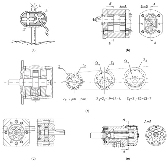
Figure 1.
Overview of hydraulic gear machines: (a) Kepler’s gear pump; (b) external gear pump; (c) internal gear pump; (d) gerotor pump; (e) orbital motor.
New development possibilities were created with the use of involute internal gearing in gear pumps, as shown in [7] and in Figure 1c. By successively reducing the tooth difference z2 − z1 between the inner and outer gears, machines with a more compact structure compared to the machines featuring external gearing were designed. Furthermore, axial and radial clearance compensation and durable housings were applied. Modern gear pumps, both the external and internal ones, generate high operating pressures of p = 20–30 MPa and perform at high total efficiency of η = 80–90%.
For the development of the theory of gear machines, the study [8] is of particular importance, indicating the principle of equivalence of mechanical and hydraulic energy as the source of equations for the determination of gear pump delivery and delivery pulsation. That work was later developed by the publications [9,10,11,12] in relation to various types of involute and cycloidal teeth. Those publications show that the use of internal gearing allows not only to obtain a system of smaller gears but also pumps with reduced pulsation of delivery and pressure, as well as reduced noise of their operation.
Further development of gear pumps was associated with the application of internal gears featuring special profiles, derived predominantly from cycloidal curves. Those teeth have been developed since the 18th century, and in the 19th century, an American, Myron F. Hill, called them “gerotor” pumps, combining the words “generated” and “rotor”. A gerotor pump is presented in [13]; Figure 1d. It has an epicycloidal gearing featuring a tooth difference of z2 − z1 = 1, which ensures the compact structure and small dimensions of the unit. At the same time, further reductions in the delivery and pressure pulsation as well as a reduction in the noise levels are obtained. Gerotor units, generally, have no axial clearance compensation and do not exceed working pressures of p = 14 MPa and efficiency η = 70–80%.
The tooth difference z2 − z1 = 1 and the smooth profile of the teeth enable the co-operation of the cycloidal gears according to the orbital motion principle. This design feature was used to build the low-speed and high-torque orbital motors shown after [14] in Figure 1e, as well as the construction of the Orbitrol steering systems.
In recent decades, a systematic development of gerotor and orbital machines has been described in a number of publications. The works deal with a variety of issues related to the machines, namely:
- The analysis of epitrochoidal curves and methods of constructing outlines of gerotor wheels [15];
- The comparison of the operation principles of gerotor and orbital machines [14];
- The history of gerotor and orbital machines’ development in the USA [16];
- The fundamentals of designing machines with cycloidal gearing [17,18,19];
- The calculation of the efficiency and pulsation of the efficiency in gerotor machines [20,21,22];
- The determination of forces and torques in the gearing of gerotor pumps [23];
- The computer simulation of the flow phenomena observed in gerotor pumps [24,25];
- The presentation of design solutions for gerotor pumps and orbital motors [26,27,28];
- The review of publications on gerotor technology and setting development trends in this field [29].
Even though each of those publications contains some scientific and technical novelty, they are focused only on a fragment of the theory and practice of gerotor and orbital machines. There are no publications which would deal with this problem synthetically.
Therefore, the general aim of the work was formulated as the development of a synthetic approach to design, manufacture and examine gerotor and orbital hydraulic machines.
Within the general objective, specific objectives can be distinguished, including the development of:
- Fundamentals of the geometry and kinematics of gerotor and orbital gears;
- Hydraulics of gerotor and orbital machines;
- Principles of manufacturing gerotor and orbital gear systems;
- Methods of examining gerotor and orbital gear systems and machines.
The presented goals were achieved using the original design method, which includes the following stages:
- Development of the theoretical foundations of gerotor and orbital gearing, including geometry and kinematics;
- Development of the basics of hydraulics for gerotor and orbital machines, including equations defining the delivery (capacity), delivery pulsation and design of the internal channels and clearances of those machines;
- Development of methods of producing gerotor and orbital systems;
- Development of simulation and experimental methods of examination of gerotor and orbital machines.
The design method containing the authors’ knowledge can be used to improve, create and investigate gerotor and orbital machines. It may be found useful both for the academia and industry.
2. Geometry and Kinematics of Gerotor and Orbital Gears
2.1. Cycloidal Curves and Cycloidal Gears
Three basic groups of curves are used in the design process, i.e., epicycloids, hypocycloids and pericycloids (Figure 2).
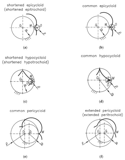
Figure 2.
Family of cycloidal curves: (a) shortened epicycloid (shortened epitrochoid), (b) common epicycloid, (c) shortened hypocycloid (shortened hypotrochoid), (d) common hypocycloid, (e) common pericycloid and (f) extended pericycloid (extended peritrochoid).
As shown in Figure 2a,b, epicycloids are formed by rolling a circle with radius (ro) and the associated point M on the outside of the basic circle with radius rb. If point M lies inside the movable gear, then a shortened epicycloid is drawn (Figure 2a). If the point is on its circumference, a common epicycloid is created (Figure 2b). When the point is outside of the rolling gear, an extended epicycloid is made.
Figure 2c,d shows that hypocycloids are formed as a result of rolling the circle with radius (ro) and the associated point M on the inside of the basic circle rb. When point M lies inside the rolling gear, then a shortened hypocycloid is generated (Figure 2c). If point M lies on its circumference, a common hypocycloid is drawn (Figure 2d). When the point is on the outside, an extended hypocycloid is created.
Sometimes, in the literature [30], pericycloids, as shown in Figure 2e,f, are described. Those curves are drawn by rolling a circle with radius (ro) and the associated point M on the outside of the basic circle with radius rb, where (ro) > rb. As in the previous cases, if point M lies inside the rolling gear, a shortened pericycloid is created. If it is located on its circumference, a common pericycloid is obtained, and if on the outside of the rolling gear, an extended pericycloid is drawn. As shown in [31], pericycloids are equivalent to epicycloids. The common pericycloid (Figure 2e) is equivalent to the common epicycloid (Figure 2b). This is additionally illustrated by Figure 3. The shortened pericycloid is equivalent to the extended epicycloid, while the extended pericycloid (Figure 2f) is equivalent to the shortened epicycloid (Figure 2a).
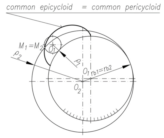
Figure 3.
Equivalence of the common epicycloid (index 1) and the common pericycloid (index 2).
In the literature [32,33,34], the term also used is “trochoid”, which, according to the mathematical Equation (30), refers to the extended or shortened cycloidal curves. Trochoids do not refer to the common curves.
A question arises, namely, which curves can be used to design gerotor and orbital gearings and how should they be named?
The common and shortened curves with no loops on their profile ought to be applied. Those curves are shown in Figure 2. The figure shows that the curves can be addressed in a variety of ways.
For example, in paper [35], the name “extended peritrochoids” is used referring to the curves which in paper [36] are called “shortened epicycloids” and in paper [37], “trochoids”. This variety of names may be the source of misunderstanding or even errors.
In this paper, the terms “cycloidal”, “epicycloidal” and “hypocycloidal curves” are used consistently, additionally modified by the adjectives “common” or “shortened”.
Obviously, even though the term “trochoidal curves” can be used, they refer only to shortened epitrochoids and shortened hypotrochoids. They do not include common epicycloids and hypocycloids which do not have loops and can be used in the design of gerotor and orbital gears (Figure 2a–e). The term “cycloidal curves” is more universal than “trochoidal curves”. The term “pericycloids” is omitted because those curves are identical to epicycloids.
2.2. Parameters of the Cycloidal (Epicycloidal and Hypocycloidal) Teeth and Gearing
As stated in Section 2, gerotor and orbital systems are treated as gear systems. A set of parameters, uniform with the involute gearing, was adopted for the description of the systems. Those are the following parameters:
- z—the number of teeth equal to the number of arcs of the epicycloid or hypocycloid found in the entire closed cycloidal curve;
- m—a module which, according to the principle of drawing cycloidal curves, is equal to the diameter of the movable gear ρ, i.e., m = 2ρ (Figure 4a);
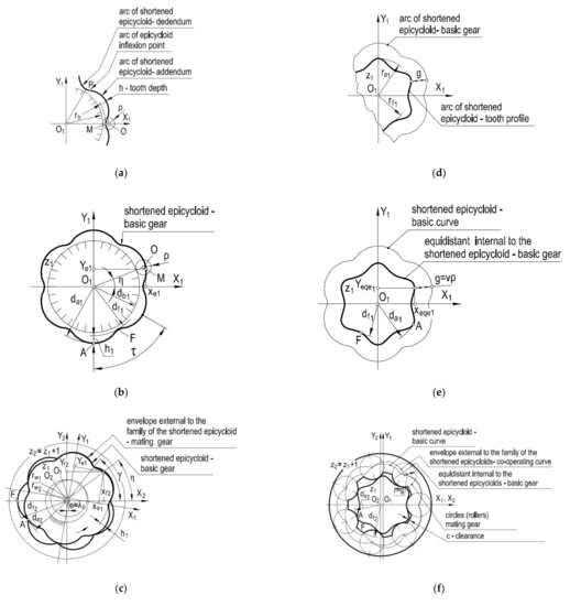 Figure 4. Design of teeth, gears and the internal epicycloidal gear systems: (a) uncorrected teeth; (b) basic uncorrected external gear; (c) mating uncorrected internal gear; (d) corrected teeth; (e) basic corrected external gear; (f) mating internal corrected gear.
 - η—cycloidal curve angle (Figure 4b);
- v—cycloidal range correction factor;
- b—tooth width.
As shown further in this paper, using these parameters, the geometry and kinematics of cycloidal gears can be described and the hydraulic parameters of machines such as delivery (capacity) and pulsation of delivery (capacity) can be determined. This indicates the universality of the adopted system of parameters and its usefulness in the entire design process.
2.3. Teeth, Gears and Epicycloidal Gear Systems
Figure 4, following [38,39,40] illustrates the principles of designing teeth, gears and epicycloidal gear systems. Figure 4a shows that a single tooth is the arc of a shortened epicycloid, which consists of a convex and concave part connected at the point of inflection P. Figure 4b shows that the teeth of the outer gear are obtained by generating the subsequent epicycloid’s arcs and connecting them into a closed curve in the form of a shortened epicycloid. Using the parametric equations of the epicycloid [30] and inserting the gearing parameters given above, the equations for determining the coordinates of the profile of the external basic gear are obtained:
According to Figure 4b, the equations for calculating the tip diameter da1 and the root diameter df1 of the external basic gear are:
The tooth depth h is defined by the equation:
Subsequently, Figure 4c illustrates the design of an internal mating gear. By rolling the basic gear with center O1 around point O2, a family of basic gears is generated. By drawing the envelope external to this family, the profile of the internal mating gear with the number of teeth z2 = z1 + 1 is defined. The shape and profile of the mating gear complete the shape and profile of the basic gear. The distance between the axes O1, O2 of both gears or, alternatively, the eccentric e is equal to:
The rolling radii of the basic and mating gears are:
The system of parametric equations describing the family of gears by the epicycloidal profile in the X2Y2 system has the form:
Equation (7) should be supplemented with the envelope condition that links the angle of rotation γ of the basic gear with respect to the mating gear with the angle of the epicycloid η (Figure 4b):
By combining Equations (7) and (8), it is possible to determine the profile of the internal mating gear. The characteristic diameters of the mating gear are determined by the following equations:
To sum up the considerations presented above, it is stated that:
- Equations (7) and (8) for determining the profile of the internal gear are difficult to use directly;
- The teeth of both gears have disturbed proportions between the head and the root, and the intertooth pressure may be too high (Figure 4c);
- Manufacturing of an internal gear of a complicated profile is difficult and expensive.
Hence, in order to eliminate the disadvantageous features of the design and manufacture, the teeth, the gears and the epicycloidal gear systems are corrected, which is also shown in Figure 4. According to Figure 4d, the tooth correction consists of the formation of the arc of the internal equidistant in relation to the arc of the shortened epicycloid, and the equidistant shift is g = vρ. Figure 4e shows that the external gearing of the basic gear is the equidistant in the form of a closed curve. The system of parametric equations describing the equidistant has the form:
Equations for calculating the tip (addendum) diameter of the gear da1 and the root (dedendum) diameter of the gear df1 in the corrected gear are:
Next, the internal mating gear is corrected. As shown in Figure 4f, from the vertices of the envelope, circles with the radius equal to the shift of the equidistant r = g are drawn, and then, those circles are connected with each other by arcs of the circle with the diameter df2, which turns from the center O2 of the mating gear. The characteristic diameters of the mating gear after the correction are defined by the equations:
The correction of the epicycloidal gears can be compared to the P−0 correction (without changing the axis distance) in classic involute gearing. It is noted that after applying the correction, the following are obtained:
- Equations which are simpler and easier to use in the design process;
- More proportionate teeth and gears;
- Manufacture which is considerably simpler and cheaper than the manufacture of the uncorrected gears, especially in the case of the internal mating gear.
2.4. Teeth, Gears and Hypocycloidal Gear Systems
Figure 5, following [38,39,40], presents the principles of designing teeth, gears and hypocycloidal gear systems. Figure 5a shows that a single tooth is formed by a shortened cycloid arc. Figure 5b, however, shows that a basic internal gear is made by joining successive hypocycloidal arcs into a closed curve in the form of a shortened hypocycloid. Utilizing the parametric equations of the hypocycloid [30] and inserting the gearing parameters into them, an equation for determining the coordinates of the basic internal gear profile is defined:
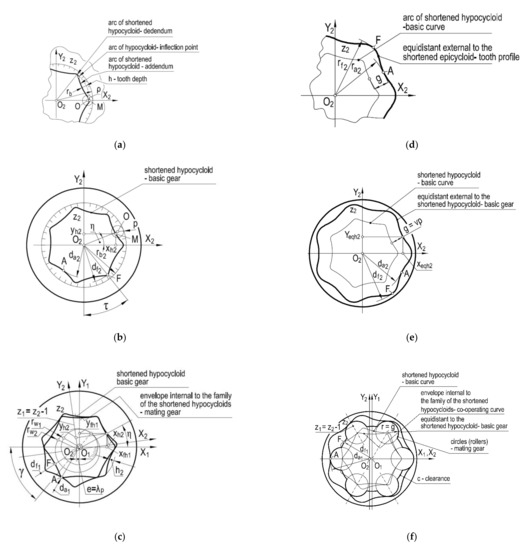
Figure 5.
Design of teeth, gears and the internal hypocycloidal gear systems: (a) uncorrected teeth; (b) basic uncorrected internal gear; (c) mating uncorrected external gear; (d) corrected teeth; (e) basic corrected internal gear; (f) mating external corrected gear.
According to Figure 5b, the equations for calculating the tip (addendum) diameter da2 and the root (dedendum) diameter df2 of that gear are:
Figure 5c illustrates the process of designing the external mating gear. By rolling the basic gear with center O2 around point O1, families of basic gears are obtained. Drawing the envelope internal to this family, the profile of the external mating gear and the number of teeth z1 = z2 − 1 are obtained.
The set of parametric equations describing the family of hypocycloidal gears in the x1, y1 system takes the form:
The relationship between the angles and γ is:
The characteristic average of the external mating gear is:
For similar reasons as in the case of epicycloidal gearing, the correction of teeth, gears and hypocycloidal gear systems is made, which is also shown in Figure 5. The main difference is that the equidistant is formed outside the shortened hypocycloid. The shift of the equidistant is similar to the one for the epicycloidal gearing, g = vρ. The system of parametric equations describing the equidistant to the shortened hypocycloid describing the teeth of the corrected basic gear is:
The equations for calculating the characteristic diameters of the corrected hypocycloidal gears are:
The correction of the hypocycloidal gear assembly is also a P−0 correction without changing the distance of the axis. As a result of this correction, the obtained design and technological advantages are similar to the ones obtained for the epicycloidal gearing.
2.5. Kinematics of Gerotor and Orbital Gears
Figure 6 shows the principles of co-operation of the cycloidal gears at fixed rotation axes O1, O2. Such co-operation takes place in gerotor machines.
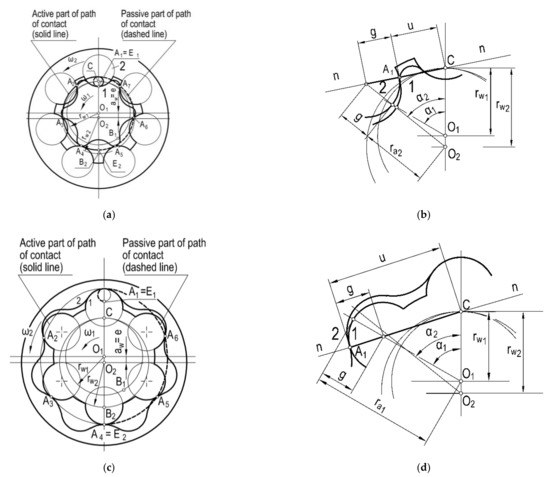
Figure 6.
Meshing of the cycloidal corrected gears with fixed axes: (a) path of contact in epicycloidal gears; (b) distance from the point of action to the pitch point in epicycloidal gears; (c) path of contact in hypocycloidal gears; (d) distance from the point of action to the pitch point in hypocycloidal gears.
It can be observed in Figure 6a that the co-operation of individual pairs of the epicycloidal teeth begins at the point of contact A1, where the so-called engagement occurs. During the rotation of the gears, the point of contact moves to the next positions A2, A3 and A4 until it reaches point An, where the disengagement occurs. Later, the point of contact returns to point A1. Looking at the entire gerotor assembly, it is noted that there are simultaneously as many points of contact as there are teeth in the mating gear. The path of contact is in the shape of a double loop, namely, a large loop around the entire gearing and a small loop around the central pitch point C. This loop resembles a conchoid [30]. The path of contact can be divided by the vertical axis of symmetry A1O1O2An into the active part (solid line) and the passive part (dashed line). In the active part, the teeth come into contact with each other and transmit the torque, while in the passive part, they come into contact by sliding on each other and do not transmit a load. The number of contacts is determined as the ratio of the CB1 gearing arc to the pw pitch on the rw1 rolling wheel, i.e.,
The value of the number of contacts exceeds 1 and is much higher than the number of contacts for the involute gearing. As a result, the gear co-operation is smoother and the pressure exerted on the teeth is reduced. Based on Figure 6b, the relation between the distance u of the point of contact A1 and the pitch point C is determined as:
Figure 6c shows that the co-operation of a single pair of hypocycloidal teeth and the entire gearing is similar to the epicycloidal gearing described above. The engagement occurs at point A1 and the disengagement occurs at point A1n. The path of contact also has the shape of a double loop and is divided by the vertical axis A1O1O2A1n into a load-carrying active part and a passive part carrying no load. The number of contacts is determined using Equation (21). The distance of point A1 from the pitch point C is determined on the basis of Figure 6d as:
Figure 7 shows the principles of co-operation of cycloidal gears at the movable axes of rotation O1, O2. Such rules apply to orbital machines. As shown in this figure, there are two variants of the co-operation. In the first of them (Figure 7a), the internal gear has a fixed axis of rotation O2 and remains fixed, and inside of it, with the planetary (orbital) motion, the external gear with the center O1 rotates. In the second variant (Figure 7b), the situation is the opposite, i.e., the external gear has a fixed axis of rotation O1 and remains fixed, while the internal gear with the center O2 moves around it in a planetary motion. In both cases, all gear teeth remain in mutual contact; therefore, the moving gear is guided by the fixed gear without the need for applying a yoke, which is necessary in the classic planetary gear transmissions. The gear movement is forced by the pressure of the working medium supplied from the hydraulic system by means of a positive displacement pump. The ratio in orbital machines is determined as the ratio of the rotational velocity of the movable gear n1 or, alternatively, n2 to the rotational velocity nJ of the yoke marked in Figure 7 with a dashed line. In the first case (Figure 7a), the ratio is:
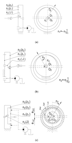
Figure 7.
Meshing of the cycloidal gears with movable axes: (a) movable external gear with the central point O1; (b) movable internal gear with the central point O2; (c) movable gearing with external and internal gearings and central point O.
This means that for the shaft associated with the movable gear z1 to make one rotation n1 = 1, the yoke should rotate z1 times, i.e., nJ = z1. The minus sign means that the yoke rotates in the direction opposite to the shaft. In the second case (Figure 7b), the ratio is:
The plus sign means that the yoke rotates according to the shaft.
Cycloidal gears can be combined into multi-gear systems, e.g., three-gear ones, as shown in Figure 7c. The co-operation in such a gearing is shown in Figure 8. Gear 2, in the form of an externally and internally toothed ring, rolls simultaneously with a planetary (orbital) motion on the fixed gear 3 and on the movable gear 1. In this situation, the O2 axis moves around the fixed O3 axis and, at the same time, around the movable, but defined, axis O1. The movement of the planet of ring 2 is caused by the injection of the working medium into the intertooth displacement chambers formed between gears 1, 2 and 3. The equation for the kinematic ratio in such a mesh is:
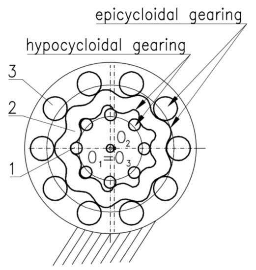
Figure 8.
Double cycloidal gearing, epicycloidal/hypocycloidal: 1—central external gear; 2—ring; 3—internal gear.
This means that gear 1 and the associated shaft rotate 2/z2 times slower than the imagined yoke that drives the active gear. The minus sign means that the yoke rotates in the direction opposite to the shaft.
3. Hydraulics of Gerotor and Orbital Machines
3.1. Delivery (Capacity) and Delivery Pulsation (Capacity) of Gerotor and Orbital Machines
In [8,9,10,11], it was demonstrated that the universal principle of mechanical and hydraulic energy equivalence can be used to calculate the hydraulic performance of gear machines (HGM). Using the model of the epicycloidal gerotor machine shown in Figure 9, this principle can be described as:
where:
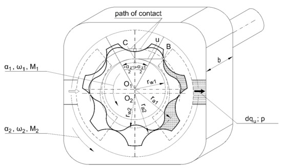
Figure 9.
Model of a gerotor machine with epicycloidal gearing.
- M1, M2—torques on the active and passive gears, respectively;
- Dα1, dα2—angles of rotation of the active and passive gears, respectively;
- qu—elementary volume delivered at the gear rotation by angles dα1 and dα2;
- Δp—pressure difference on the inlet and outlet of the pump, approximately equal to the delivery pressure Δp = p.
After the transformations presented in detail in [41,42,43], the equation for the elementary delivery is defined:
where b—gear width.
Having done the integration in the range from α1 = − αz1/2 to α1 = + αz1/2 (see Figure 9), delivery qz corresponding to the rotation of the gears by one angular pitch, namely by one tooth, is determined:
Multiplying the delivery qz by the tooth number z1, the delivery q displaced from the pump by the z teeth is determined, i.e., the delivery by one revolution of the drive shaft, also called the specific delivery:
Considering Equations (6), (11), (12) describing radius rw1, rw2, ra1, ra2, as well as Equation (22) defining the point of contact u, and carrying out all necessary transformations, the equation for the specific delivery qe of the gerotor pump or, alternatively, for the capacity of the epicycloidal gear motor is determined:
This equation uses the number of teeth z1 because, according to the design rules (Figure 4), the basic gear in the assembly is the external gear.
Using the model of the hypocycloidal gerotor machine shown in Figure 10 and carrying out similar calculations as the ones presented above, using dependencies (14, 17, 23, 28), the equation for the specific delivery qh of the gerotor pump relative to the capacity of the hypocycloidal motor is obtained:
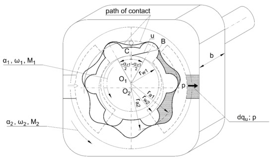
Figure 10.
Model of a gerotor machine with hypocycloidal gearing.
The number of teeth is used in the equation because the basic gear in the system is the external gear (Figure 5).
Equations (31) and (32) are easily applicable in engineering practice. They enable determination of the impact of a design solution and the parameters of epicycloidal or hypocycloidal gearing on the performance (capacity) of the machine. Irregularity of delivery (capacity) or flow (capacity) pulsation is determined by means of the defining equation given, among others, in [20,42] as:
In the case of the machines with epicycloidal or hypocycloidal gearing considered in Figure 9 and Figure 10, the maximum instantaneous delivery Qu max will be obtained for umax, i.e., for the angle of rotation of the inner gear α = ± αz1/2, and the minimum delivery for umin, i.e., for the angle of rotation α = 0. The average delivery is obtained as (Qu max + Qu max)/2. After detailed calculations shown in [42], the equations for the delivery pulsation of the machines with epicycloidal gearing are finally obtained:
Furthermore, for the hypocycloidal gear machines:
Equations (34) and (35) describe the pulsation of delivery (capacity) are more complicated than Equations (31) and (33) regarding delivery. However, these equations also allow to study the influence of a design solution and cycloidal tooth parameters on the value of delivery pulsation.
As shown in Figure 9 and Figure 10, the gears in gerotor machines work at fixed axes. Hence, as a result of one rotation of the machine drive shaft, one rotation of the driving (basic) gear and, consequently, the so-called specific delivery qe or qh are generated. This delivery can be determined by means of Equations (31) and (32). In the orbital machines shown in Figure 7, the gear axes are movable. In this situation, one rotation of the shaft results in a multiplied number of revolutions of the yoke and of the driving (basic) gear connected to it. When the external gear (Figure 7a) is driven, according to Equation (24), the number of rotations is n1 = z1, and when the internal gear (Figure 7b) is driven, according to Equation (25), the number of rotations is n1 = z2. As a result, the delivery (capacity) of an orbital machine is determined by the formula:
where:
- qorb—delivery (capacity) of the orbital machine;
- q(e, h)—delivery (capacity) of the gerotor machine calculated according to Equation (31) or (32);
- n1 = z1 or z2—number of rotations of the driving gear per one revolution of the drive shaft.
3.2. Shaping the Arrangement of Internal Channels and Clearances in Gerotor and Orbital Machines
The gear system of a gerotor or orbital machine co-operates with a system of internal channels and clearances formed in the body of the machine, ensuring the inflow and outflow of the working medium. There are two basic systems of channels and clearances. Those are:
- System of fixed channels;
- System of movable channels.
A diagram of a system of fixed channels is shown in Figure 11. It consists of:
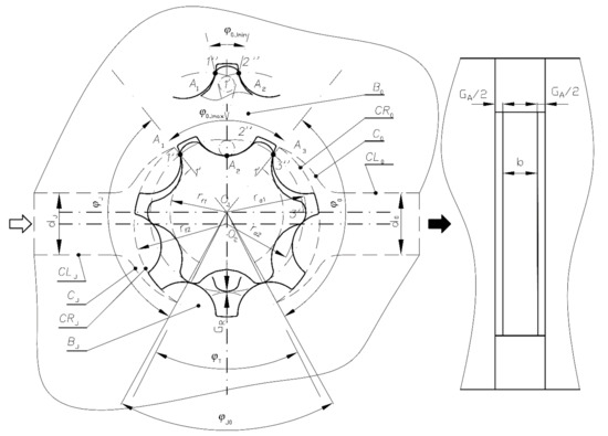
Figure 11.
The system of fixed channels and clearances in gerotor machines: J—inlet port; O—outlet port; CLJ, CJ, CRJ, BJ—inlet channel, inlet chamber, inlet bridge; CLO, CO, CRO, BO—outlet channel, outlet chamber, outlet bridge; GA—axial clearance; GR—radial clearance; d, d0—diameters of inlet and outlet ports; 1′, 1″, 2′, 2″, 3′, 3″—teeth; A1, A2, A3—intertooth contact points; ra1, ra2—addendum radius; rf1, rf2—dedendum radius; φJ, φJO, φO, φoJ—angles of inlet, inlet bridge, outlet, outlet bridge; ϕT—angle of intertooth displacement chamber; b—gear width; e = O1, O2—center distance.
- Inlet channel CLI, inlet chamber CRI and inlet bridge BI;
- Outlet channel CLO, outlet chamber CRO and outlet bridge BO;
- Axial clearance GA;
- Radial clearance GR.
As shown in Figure 9 and Figure 10, the gears in gerotor machines work at fixed axes. Hence, as a result of one rotation of the machine drive shaft, one rotation of the driving (basic) gear and, consequently, the so-called specific delivery qe or qh are generated. The shape and dimensions of the channels and clearances result directly from the shape and dimensions of the gears. Therefore, in Figure 11, the channels are drawn with a dashed line against the background of the gears drawn with a solid line.
The CLI inlet channel is shaped as a cylinder of a diameter equal to or greater than the width of the gear system dI ≥ b. This channel grows wider in the form of a “chalice” CI and is connected to the CRI inlet chamber. The inlet chamber is located in the side body of the pump and has the shape of a kidney widening within the angle φI, and its arched walls are defined by the root radius rf1 of the external gear. The CLO outlet channel and the CRO outlet chamber are shaped in a similar way.
The inlet bridge is a fragment of the side body that separates the inlet zone from the outlet zone. It extends within the angle φIO, which is larger than the angle of the displacement chamber φT. The CRO outlet chamber, narrowing in the form of a “chalice”, CO and the CLO outlet channel with the diameter do are similar in shape to their counterparts on the inlet side.
The outlet bridge is also a fragment of the side body, separating the inlet and outlet zones. It extends within the angle φIOmin–φIOmax.
As shown in the upper part of Figure 11, the first minimum value of the angle φIOmin appears when tooth 1′ of the external gear is in the central position on the axis O1, O2 and its sides co-operate with points A1 and A2 with two adjacent teeth, 1″ and 2″ of the internal gears. The minimum outlet bridge φIOmin extends between the points of contact A1 and A2. At the same time, the lower part of Figure 11 shows that the second maximum value of the angle φIOmax appears when the next tooth 2′ of the external gear starts co-operating with tooth 2′ at point A2. In this situation, the preceding pair of 1′ and 1′’ teeth co-operate at point A1 and the following pair of 2′ and 3′ teeth contact each other additionally at point A3. The maximum outlet bridge extends between points A1 and A3 in the angle range φOImax. The minimum bridge (φOImin) ensures separation of the inlet and outlet zones, but in practice, when there are manufacture inaccuracies and deformation of the machine components, the minimum bridge (φOImax) may not be sufficient. Simultaneously, the maximum bridge (φOImax) may turn out to be too large and cause accumulation of the working medium in the intertooth spaces. Finally, the outlet bridge remains in the range φOImin < φOI < φOImax. Corresponding to the bridge angle φOI, the angle of the inlet chamber φI and the outlet chamber φO increase. The axial GA and the radial GR clearances are formed, taking into account two basic requirements for the operation of the gear assembly. On the one hand, the intention is to keep these clearances as small as possible (going to zero) in order to maintain high internal tightness of the machine. On the other hand, the minimum values of these clearances should be maintained to ensure smooth friction between the gear teeth, the gear assembly and the body. The optimum values of the axial clearance are GA allow = 0.02–0.05 mm and the radial clearance GRallow = 0–0.1 mm [42,43].
In orbital machines featuring gear systems with movable axes, movable systems of channels and clearances are used. According to [44], two basic types are distinguished:
- A system of channels built on the basis of a rotary distributor, in which the channels and clearances are formed between a rotating shaft (sleeve) and a fixed housing;
- A system of channels made using a disc distributor, in which the channels and clearances are formed between the rotating and the fixed disc of the distributor.
The detailed solution of the arrangement of the channels and clearances depends on the design of the machine and is different for different types of machines. The problem was considered specifically by the example of the MAX orbital hydraulic motor, where double cycloidal gearing, previously presented in Figure 8, was utilized. There, a movable channel system designed using a disc distributor was applied. It is presented in [42,45] and in Figure 12 and consists of a system of inlet (high pressure) channels, marked in black, and a system of outlet (low pressure) channels, marked in white.
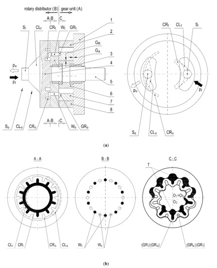
Figure 12.
System of the internal channels and clearances in the MAX orbital motor of the fourth group of the machines: 1,2,3,4—housing elements; 5—shaft; 6,7,8—cycloidal gear; SI, CLI, CRI, WI, GRI—slot, channel, chamber, window, inlet groove; SO, CLO, CRO, WO,GRO—slot, channel, chamber, window, outlet groove.
Figure 12, in the main view, depicts the working medium flowing into the rear cover of the machine (4), and next, through the cylindrical inlet socket (SI) and the cone-shaped inlet channel CLI to the CRI kidney-shaped inlet chamber. Figure 12, in the cross-section A-A, shows that this kidney is transformed into the circular chamber CRI and the grooves going radially outside that chamber. Figure 12, in the cross-section B-B, presents the radial grooves supplying the working medium to the round WI inlet windows located in the intermediate cover (3). Consequently, cross-section C-C shows that the windows connect to the CRI grooves located on the side planes of the orbiting toothed ring (7). One part of the grooves is directed towards the outer intertooth chambers T formed between the toothed ring (7) and the internal toothed gear (8). The second part of the grooves is directed to the inner chambers T formed between the ring (7) and the gear (6). When half of the outer and inner chambers reach their maximum volume (Figure 12, cross-section C-C) and the toothed ring (7) rolls on, then the GRI inlet grooves roll along with it and are transformed into GRO outlet grooves. As a result, the working medium is discharged on the way: window (WO); circular chamber (CRO); channel CLO; socket S. The main view in Figure 12 also shows the internal clearances, i.e., the axial clearance GA and the radial clearance GR, occurring in the orbital motor. The principles of their shaping are similar to those observed in the gerotor machines.
4. Manufacturing of the Gerotor and Orbital Gear Systems
Two methods of making cycloidal teeth of gerotor and orbital machines can be distinguished:
- The method in which the path of the universal tool maps the profile of the gearing;
- The method in which the shape of the cutting edge of a special tool copies the form of the gearing.
Both methods are closely related to the geometry and kinematics of the gears presented in Section 3 of this paper. The principles of making the gearing according to the first method, following [44], are presented in Figure 13a–c. Figure 13a,b depict that they are manufactured using two-lip end mills of diameters d1 or d2, which move along the line mapping the profile of the gearing. It is a line parallel to the theoretical profile of the teeth, which is described by Figure 4e or Figure 5e and Equation (16) or Equation (18). The path of the tool must be defined in the numerically controlled milling machine, taking into account the diameters d1 and d2 of the cutters. The diameter d1 should be as large as possible so that the cutter does not bend while machining, and the diameter d2 must be smaller than the width of the intertooth space so as to ensure free movement of the cutter in the groove of the gear during machining. Grinding of the teeth can be carried out using the same method, by means of finger-shaped grinders. The described method is also used in the case of electrical discharge machining, as shown in Figure 13c [44]. Accuracy of the gearing can be ensured by using, among others, low-speed machining and by repeating the process several times.
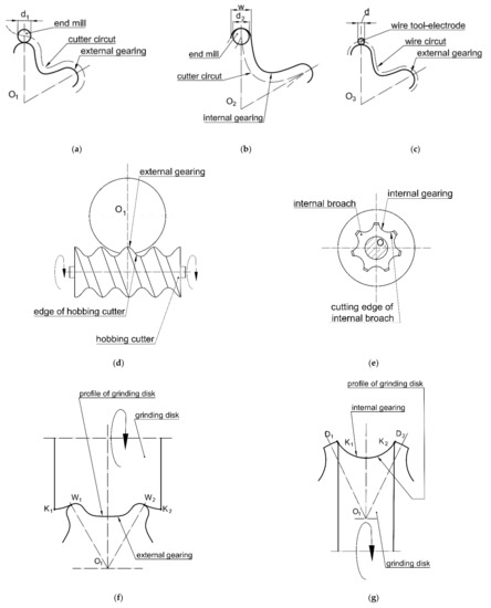
Figure 13.
Methods of manufacturing cycloidal teeth: (a,b)—cutting; (c)—electrical discharge machining; (d)—hobbing; (e)—broaching; (f,g)—grinding.
The principles of manufacturing the teeth by means of the second method are presented in [44] and in Figure 13d–g. Figure 13d shows that the external gearing is made using a gear cutting hob. Figure 13e, however, shows that the internal gearing can be made by broaching, using a special broach, whereas in Figure 13f,g, it is presented that grinding of the teeth is carried out with the use of grinders of special profiles. In all the cases presented, the cutting tool closely reproduces the gear tooth profile. It can be said that the cutting edge is a negative of the tooth profile. Furthermore, in this method, the cutting edges are formed according to Figure 4e or Figure 5e and Equation (10) or (18).
The results of utilizing both of these methods are presented in Figure 14. Figure 14a–c depict the cycloidal gearing made by the finger-shaped grinding. Figure 14d–f show the gearing made by the electrical discharge machining. Figure 14g,h present the gears made by means of hobbing and shape grinding. The last group, presented in Figure 14j–l, are gear systems made of plastics [46,47]. The gears depicted in Figure 14j,f were made by means of a two-lip end drill, whereas the gear shown in Figure 14l was manufactured by injection molding. Both the injection mold and the process are described in [44].
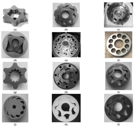
Figure 14.
Gerotor and orbital gear systems manufactured using different methods: (a–c)—systems manufactured by the use of an end mill; (d–f)—systems manufactured by the use of electrical discharge manufacturing; (g–i)—systems manufactured by the use of hobbing, broaching and grinding; (j–l)—plastic systems manufactured by the use of injection molding and hobbing.
5. Examination of Gerotor and Orbital Machines
Research on gerotor and orbital machines is carried out in two basic forms, i.e., in the computer or experimental form. The computer research is carried out during the design process using virtual models. Its purpose is to initially verify the design solution of the machine and to predict the processes and phenomena, the occurrence of which should be expected in it. Experimental research is conducted at the end of the design process, using real machine models. Its aim is to finally verify the machine by examining its operation, determining its technical parameters and examining the real processes and phenomena which occur in it.
The best solution seems to be a combination of computer and experimental research. In such a case, the research process can be carried out by cascading from the simulation to the experimental research and, optionally, implementing feedback between them. The combined research results are complementary and give a synergistic effect. Characteristic examples of such research are presented in the paper.
5.1. Forecasting of the Axial and Radial Clearances and Working Pressures in a Pump with Gerotor Wheels Made of POM
The object of the research was an epicycloidal gerotor system designed according to Figure 4f and Equations (10) and (12). A special feature of the assembly was that it was made of Polyoxymethylene (POM), which has a much lower yield point Re than steel. Therefore, both different gear co-operation and technical parameters can be expected.
It is assumed that the computer model of the gerotor system features no axial and radial clearances, i.e., GA = 0 and GR = 0.
A computer study using the Finite element method (FEM) method on a model of a virtual gerotor assembly was conducted [45]. The aim of the study was to define the principles of co-operation of the system and to determine the scope of their load capacity in the aspects of strength and hydraulics. The results of the study are shown in Figure 15.
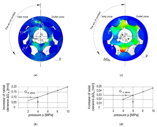
Figure 15.
Results of the strength analysis of the epicycloidal gerotor systems by use of the FEM method: (a)—stress distribution; (b)—strain distribution; (c)—increase in radial clearance ΔGR depending on the working fluid pressure p; (d)—increase in axial clearance ΔGA depending on the working fluid pressure p.
The principles of the co-operation can be analyzed in Figure 15a,b. The figures show that the gerotor assembly is loaded with torque M transmitted from the drive shaft by means of three keys and pressure p of the working medium acting on the intertooth displacement chambers in the outlet zone. The torque M and pressure p make the teeth of both gears co-operate in the inlet zone within the arc of contact. Forces F1, F2 and F3 are generated between the teeth, and the ratio of the forces is approximately 3:2:1. Those forces generate stresses σ1, σ2 and σ3 the mutual ratio of which is similar to the ratio of the forces. Figure 15b shows that under pressure, the gerotor assembly is deformed. The external gear (the “star”) with center O1 moves towards the inlet zone and, simultaneously, its teeth are deformed in that direction. The internal gear with the O2 center (the “ring”) moves towards the outlet zone and its teeth are similarly deformed. As a result of the deformation of both gears, the intertooth clearances in the outlet zone and the largest radial intertooth clearance ΔGR between the teeth located on the border between the inlet and outlet zone are created.
Figure 15b shows that loading the gear assembly with pressure p acting on its front surface causes its compression, as a result of which additional axial clearance ΔGA appears. Figure 15c,d show the dependence of the clearances ΔGR and ΔGA on the working pressure p acting on the gerotor assembly. It can be observed that an increase in those clearances is directly proportional to the pressure.
The load capacity should be determined from the point of view of two criteria: the strength criterion and the hydraulic criterion. Considering the strength criterion, it should be checked whether the maximum intertooth stresses σ1, σ2 and σ3 are lower than the allowable stresses, which, for POM, are equal to the yield point Re = 40 MPa, i.e., σ1, σ2 and σ3 ≤ Re. This condition for the considered system of gerotor POM wheels loaded with torques M = 0.18 Nm and pressure p = 10 MPa has the form σ ≤ 40 MPa. In practice, this means that the deformation of the teeth is elastic, i.e., when relieved, the teeth return to their original shape.
When considering the hydraulic criterion, it ought to be checked whether the assembly intertooth clearance (radial GR or axial GA) enlarged by the increase in the clearance ΔGR or ΔGA, is smaller than the allowable radial clearance GR allow = 0.1 mm or axial clearance GA allow = 0.05 mm, which was adopted in Section 5 due to the internal tightness of the gear system [42,43]. These dependencies can be expressed as:
Using Figure 15c,d, certain prognoses can be made. It is assumed that the gerotor assembly will be made with high accuracy, i.e., the radial assembly clearance will be GR = 0 mm and the axial clearance GA = 0.01–0.02 mm.
According to Equations (37) and (38): 0 + ΔGR ≤ 0.1 mm for the radial clearance, 0.01–0.02 + ΔGA ≤ 0.05 mm for the axial clearance. Hence, the allowable increase in the clearance due to the strains are: ΔGR <= 0.1 for the radial clearance and ΔGA <= 0.03–0.04 for the axial clearance.
Figure 15c,d show that the radial increase ΔGR = 0.1 mm corresponds to pressure p = 4 MPa while the axial increase ΔGA = 0.03 mm corresponds to pressure p = 6 MPa. Taking into account both limitations, it can be anticipated that the system of gerotor wheels made of POM can work within the pressure range p = 4–6 MPa.
The prognosis resulting from the computer study was verified experimentally. The study was carried out using a gear system made of POM and manufactured in accordance with Equation (10) by a finger-shaped cutter (Figure 14f). The gear system was closed in a rigid housing made of an aluminum alloy (Figure 16a). The assembly axial clearance was GA = 0.02 mm and the radial clearance was GR = 0.0 mm. The results of the volumetric efficiency tests are shown in Figure 16b.
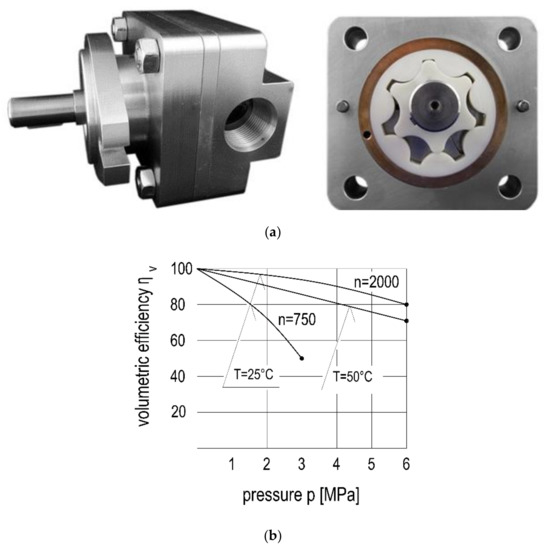
Figure 16.
Experimental gerotor pump with plastic epicycloidal gearing: (a)—view of the pump; (b)—volumetric efficiency ɳv.
The figure shows that the gear system worked correctly within the working pressure range of p = 3–6 MPa, at the volume efficiency of ηr = 80–50%. The research results suggest that the increases in the radial clearance ΔGR and the axial clearance ΔGA were in the anticipated range and the total value of the axial and radial clearances remained in the range of the allowable values, calculated from Equations (36) and (37). The experimental studies have also shown that using the higher rotational velocity of n = 2000 rpm and the working medium at the lower temperature of T = 25 °C (higher viscosity), higher working pressure p and volumetric efficiency ηr can be obtained. Such operating conditions ensured an increased frequency of the pumping process at reduced flow rates through the internal clearances in the pump, which provided higher volumetric efficiency.
The described research on the gerotor system made of POM shows that by combining the computer and experimental research methods, more complete and more reliable results are obtained. Consequently, it is possible to define an improved design of the gerotor system.
5.2. Research into the Hydraulic Processes and Phenomena in the Internal Channels and Clearances of the Gerotor Pump
The object of the research was a theoretical model of a gerotor pump with epicycloidal gearing, designed according to Equations (10) and (12), and a system of internal channels and clearances, designed according to Figure 11. In [48], a theoretical model describing the course of the flow processes occurring inside the displacement chamber of a gerotor pump was developed. The general Equation for determining the pressure pt in the displacement chamber of the gerotor pump depending on angle φ, describing the position of this chamber, has the form:
where:
- pt—pressure in the displacement chamber T;
- φ—angle determining the location of the displacement chamber T;
- VT—displacement chamber volume;
- QG—main flow rate;
- QTI—leakage flow rate on the way: displacement chamber–inlet chamber (suction chamber);
- QOT—leakage flow rate on the way: outlet chamber (discharge)–displacement chamber.
In the model, the volume of the displacement chamber VT and the flow rates QG, QTI and QOT are closely related to the geometrical parameters of the gearing (z, m, λ, υ), the working fluid compressibility modulus (Ec) and the machine operating parameters (n, T, po). Using the theoretical model, a special computer program was developed to calculate the pressure pt in the intertooth displacement chamber T. The purpose of the computer research was to determine the pressure range pt in the displacement chamber T during the full working cycle, i.e., during suction, pressure increase, discharge and pressure drop or rotation displacement chamber with the angle φ = 2π. Based on that diagram, it can be predicted whether the pump designed in accordance with Equations (10) and (12) and Figure 11 will work properly. In other words, it can be predicted whether the gerotor system will work properly with the system of internal channels and clearances. Selected results of the simulation are presented in Figure 17a,b. Figure 17a shows that the intertooth displacement chamber rotates successively through the following zones: the inlet zone (φI), the pressure increase zone (φIO), the outlet zone (φO) and the pressure drop zone (φoI). It can be observed in Figure 17b that the pressure pt in the chamber changes the value from pT = pI ≈ 0 in the inlet zone to pT = po = 8 MPa in the outlet zone (the pressure assumed in the simulation process).
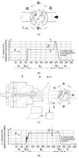
Figure 17.
Research of pressure pT in the displacement chamber T of the gerotor pump during the full working cycle: (a) division into the internal working zones φJ, φJO, φO, φOJ; (b) results of pressure simulation pT = f(ψ); (c) view of the experimental gerotor pump (S—pressure sensor; D—device; A—amplifier; C—computer); (d) results of the experimental pressure research pT = f(ψ).
On the borders of the pressure rise zone, there is a slight decrease and increase in the pressure caused by mismatch of the chamber dimensions to the dimensions of the inlet bridge. A similar situation occurs at the border of the pressure drop zone where the mismatch causes a significant pressure surplus in the intertooth displacement chamber with a value of Δp = 5 MPa, which means that the pressure pt in the displacement chamber exceeds the outlet pressure pO by more than 50%. The prognoses resulting from the computer analysis were experimentally verified. An experimental gerotor pump was built as shown in Figure 17c. The gearing was designed according to Equations (10) and (12) and was manufactured by means of a gear cutting hob (Figure 13d) and by broaching (Figure 13e). The gear was ground with specially shaped grinders (Figure 13f,g). A ready-made gear system is shown in Figure 14l. A characteristic feature of the experimental pump was the miniature pressure sensor S installed in an intertooth space of the external gear, which, through the device D, was connected with the amplifier A and the computer C. The entire system was used to measure the pressure in the intertooth displacement chamber T during the operation of the pump. The results of the experimental study are presented in Figure 17d.
The figure shows that pressure pt in the intertooth displacement chamber changes according to similar principles as in the virtual model (Figure 17b). There are the same zones: the inlet zone (φI), the pressure increase zone (φIO), the outlet zone (φO) and the pressure drop zone (φoI), where the pressure in the chamber assumes similar values. At the same time, it is noted that in the zones of the increase (φIO) and decrease (φOI), the change in pressure pt is different than that predicted in the virtual model. In the increase zone (φIO), there is a significant pulsation of pressure pt, while in the decrease zone (φOI), there is a significant reduction in the pressure surplus up to the value of Δp = 1 MPa. The reduction in the pressure surplus in the decrease zone (φOI) is explained by the fact that the GA axial clearance in the experimental pump was about twice as large as the clearance in the virtual model. Through that enlarged clearance, there is an easier outflow of the working medium from the intertooth displacement chamber and, as a result, a drop in pressure pt.
In order to explain the pressure pulsation in the increase zone (φIO), a visualization study using the Particle Image Velocimetry (PIV) method was conducted according to the principles given in [42,49]. The object of the research was the special gerotor pump presented in Figure 18a, in which the rear body was made of technical glass, enabling observation of the flow processes taking place inside the pump.
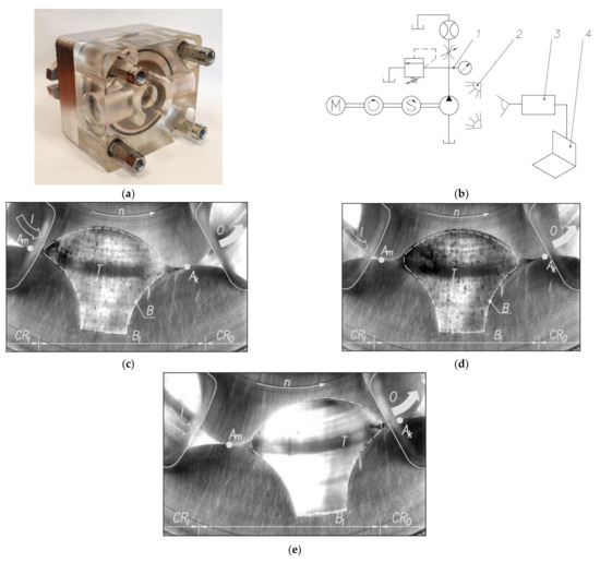
Figure 18.
Visualization study using the PIV method: (a) experimental gerotor pump; (b) examination stand (1-hydraulic system; 2—illuminative system; 3—high speed camera; 4—computer); (c–e) view of the flows through inlet bridge B, (φJO) cooperating with displacement chamber (T).
The gearing and the system of channels and clearances were the same as in the previously studied experimental pump. The pump with the transparent housing was studied in a special stand, the diagram of which is illustrated in Figure 18b. The results of the visualization study are presented in Figure 18c–e. Figure 18c shows that the intertooth displacement chamber T entered the pressure increase zone φI, i.e., the BI inlet bridge. When it is completely closed and, at the same time, its volume increased, cavitation in the form of bubbles B appeared. With further rotation of the T chamber, shown in Figure 18d, the cavitation increased, which can be observed in the form of a larger number of bubbles. Finally, when leaving the pressure increase zone, depicted in Figure 18c, and reducing the volume of the T channel, the cavitation stopped. The cavitation phenomena are the main reason for the pressure pulsation presented in Figure 17d in the pressure increase zone φIO.
The integrated computer and experimental research proves that using this method, it is possible to explain complex flow processes and phenomena occurring in the internal channels and clearances of a gerotor machine. At the same time, this combined research method can be used as a tool to improve the system of channels and clearances in gerotor and orbital machines.
6. Conclusions
A synthetic approach to the design, manufacture and examination of gerotor and orbital hydraulic machines has been developed. The paper has been prepared on the basis of the authors’ own theoretical analyses, experimental research and design solutions.
The following scientific and technical effects have been obtained:
- A uniform system of parameters and basic concepts regarding toothing and cycloidal gearing (z, m, λ, v, g) which is consistently used to describe the geometry, kinematics, hydraulics and manufacture of those elements; that system is compatible with the system applied for involute gearing, which allows for comparing the cycloidal and involute gears;
- Description of the geometry and kinematics of epicycloidal and hypocycloidal gears with the use of the adopted parameters system. Additionally, epicycloidal/hypocycloidal double gearing is presented, which is an original idea of the authors;
- Description of the hydraulics of gerotor and orbital machines, and in particular,
- Determination of equations for delivery (capacity) q and irregularity of delivery (capacity) Δ using the above-mentioned system of basic parameters;
- Formulation of the principles of designing internal channels and clearances in gerotor machines and presentation of the original disc distributor in the epicycloidal/hypocycloidal orbital motor;
- Presentation of the methods of manufacturing epicycloidal and hypocycloidal gearings and of 12 examples of the systems implemented in practice, which proves the above-mentioned theoretical formulas to be correct and useful;
- Presentation of the research methods applied for the examination of the gerotor machines, combining computer simulation and experimental research into a coherent and cohesive whole, which results in the effect of research synergy. That concerned:
- Methods of modeling axial and radial clearances in gerotor assemblies using FEM and experimental tests;
- Methods of studying the hydraulic processes and phenomena in the gerotor pump using the authors’ own computer program as well as the pressure analysis and the PIV visualization analysis.
The confirmation of the value and applicability of such integrated scientific and technical knowledge was in the creation of innovative technical solutions for gerotor and orbital machines, such as:
- A gerotor system for the Orbitrol steering blocks and the orbit motors [38];
- A gerotor pump with electromagnetic drive [50];
- A low-speed orbital motor with double epicycloidal–hypocycloidal gearing [45];
- A gerotor pump with plastic gears [46].
To sum up, it can be stated that the presented synthesis may be the subject of further research and development conducted by academia. It can also be recommended to industry as an advanced scientific and technical tool for improving, creating and investigating gerotor and orbital machines.
Author Contributions
Concept of the article was prepared by J.S.; methodology, writing, editing was prepared by J.S. and P.S. All authors have read and agreed to the published version of the manuscript.
Funding
Publication of the article was founded by Department of Fundamentals of Machine Design and Mechatronic Systems on Faculty of Mechanical Engineering at Wrocław University of Science and Technology.
Conflicts of Interest
The authors declare no conflict of interest.
References
- Abel, F. Johannes Kepler and His Importance to Modern Science; Inter Nationes Verlag: Bonn—Bad Godesberg, Germany, 1971. [Google Scholar]
- Beck, T. Jean Leurechon (1591 bis 1670). Z.d. VDI Bd. 1901, 45, 1498. [Google Scholar]
- Feldhaus, F.M. Die Technik der Vorzeit, der Geschichtlichen Zeit und der Naturvolker; Verlag von W. Engelmann: Leipzig/Berlin, Germany, 1914. [Google Scholar]
- Leupold, J. Teatrum Machinarum Hydrotechnicarum; Christop Zunkel Verlag: Leipzig, Germany, 1724. [Google Scholar]
- Wieczorek, K. PZ4-pompy zębate czwartej generacji. Hydraulika i Pneumatyka 2004, 1, 17–19. (In Polish) [Google Scholar]
- Borghi, M.; Zardin, B. Modelling and simulation of external gear pump and motors, Disussing the Influence of Elastohydrodynamic Lubrication in the Axial Clearance. In Proceedings of the 5th FPNI PhD Symposium, Crakov, Poland, 1–5 July 2008; pp. 323–341. [Google Scholar]
- Pippes, R.; Mayer, C. Clearance-compensated high-pressure internal pumps. In Proceedings of the 3rd International Fluid Power Conference, Aachen, Germany; 2002; pp. 203–214. [Google Scholar]
- Amann, R. Zahnradpumpen mil Evolventen Verzalmung. In Mitteilungen des Hydraulischen Instituts Technischen Hochschule Munchen, Heft 1; Verlag Oldenburg: Munchen, Germany, 1926. [Google Scholar]
- Willekens, F.A.M. Instantes Fordervolumen, geometrisches Hubvolumen und Ungleichformigkeitsgrad von Zahnradpumpen. Industrie-Anzeiger 1971, 26, 549–554. [Google Scholar]
- Gutbrod, W. Forderstrom von Aussen und Innenzahnradpumpen und seine Ungleichfórmigkeit. Olhydraulik und Pneumatik 1975, 2, 236–241. [Google Scholar]
- Gosele, R. Volumenstromschwankungen zykloidisch und aquidistant zykloidisch verzahnter Pumpen. Industrie Anzeiger 1979, 68, 25–26. [Google Scholar]
- Stryczek, J. Pompy zębate o zazębieniu ewolwentowym. Przegląd Mechaniczny 1978, 7, 5–10. (In Polish) [Google Scholar]
- Scholler, K. Die Ring-Rotor-Pumpe ein gerauscharmer Hydrogenerator. Oelhydraulik und Pneumatik 1974, 5, 396–398. [Google Scholar]
- Ohrberg, C.V. Comparaisions entre le moteur gerotor et le moteur orbit. EFL HPA 1969, 7, 11–13. [Google Scholar]
- Nag, A.; Maiti, R. Unification of epitrochoid origin profile design approaches for external lobed star member used in hydrostatic and gear units. Proc. Inst. Mech. Eng. Part C J. Mech. Eng. 2012, 227, 299–310. [Google Scholar] [CrossRef]
- Pippenger, J.J.; Dong, J.X. History of Gerotor Hydraulics; SAE Off-Highway Engineering; SAE: Warrendale, PA, USA, 2004; Volume 2, pp. 40–45. [Google Scholar]
- Birjukow, B.N. Rotarno-Porsniewyje Gidrawlićeskie Masiny; Masinostrojenie: Moscow, Russia, 1972. (In Russian) [Google Scholar]
- Shannikov, V. Planetarnye Reduktory s Vniecentroidnym Ceroinym Zaceplieniem; Masgiz Izdatielstvo: Moscow, Russia, 1948. (In Russian) [Google Scholar]
- Bashta, T.M. Mashinostroitielnaja Gidravlika; Izdatielstvo Mashinostrojenie: Moscow, Russian, 1971. (In Russian) [Google Scholar]
- Stryczek, S. Napęd Hydrostatyczny—Elementy; Wydawnictwa Naukowo—Techniczne: Warsaw, Poland, 1990. (In Polish) [Google Scholar]
- Colbourne, J.R. The geometry of Trochoid Envelopes and Their Application in Rotary Pumps. Mech. Mach. Theory 1974, 4, 421–435. [Google Scholar] [CrossRef]
- Colburne, J.R. Gear Shape and Theoretical Flow Rate in Internal Gear Pumps. Trans. CSME 1975, 3, 215–223. [Google Scholar] [CrossRef]
- Ivanovic, L.; Deredzic, G.; Miric, N.; Cukovic, S. Analysis of forces and torques in gerotor pumps. Proc. Inst. Mech. Eng. Part C J. Mech. Eng. 2010, 224, 2257–2269. [Google Scholar] [CrossRef]
- Castilla, R.; Gamez-Montero, P.; Raush, G.; Codina, E. Method for Fluid Flow Simulation of a Gerotor Pump using Open FOAM. J. Fluid Eng. 2017, 139, 1–9. [Google Scholar] [CrossRef]
- Pellegri, M.; Manne, V.; Vacca, A. A simulation Model of Gerotor Pumps Considering Fluid—Structure Interaction Effects: Formulation and Validation. Mech. Syst. Signal Proc. 2020, 140, 106720. [Google Scholar] [CrossRef]
- Eisenmann, S.A. Neue Trochoideninnenzahnradpumpe mit Geringer Pulsation und extrem ruhigem Lauf. Oelhydraulik und Pneumatik 1973, 4, 302–311. [Google Scholar]
- Wusthof, P.; Schneider, J. Grundlagen der Planetmotoren—Vorstellung eines neuen Planetmotors. Oelhydraulik und Pneumatik 1981, 2, 91–94. [Google Scholar]
- Manco, S.; Narvegna, N.; Rundo, M.; Margaria, M. Miniature gerotor pump prototype for automotive applications. In Proceedings of the 3rd JFK International Fluid Power Conference, Aachen, Germany, 5–6 March 2002; pp. 153–167. [Google Scholar]
- Gamez-Montero, P.; Codina, E.; Castilla, R. A Review of Gerotor Technology in Hydraulic Machines. Energies 2019, 12, 2423. [Google Scholar] [CrossRef]
- Bronsztejn, J.N.; Siemiendiajew, K.A. Matematyka, Poradnik Encyklopedyczny; PWN: Warsaw, Poland, 1970. (In Polish) [Google Scholar]
- Litvin, F.L. Tieorja Zubcatyh Zaceplieni; Izdatielstvo Nauka: Moscow, Russia, 1968. (In Russian) [Google Scholar]
- Gamez-Montero, P.; Antoniak, P.; Castilla, R.; Freire, J.; Krawczyk, J.; Stryczek, J.; Codina, E. Magnet-Sleeve-Sealed Mini Trochoidal-Gear Pump Prototype with Polymer Composite Gear. Energies 2017, 10, 1458. [Google Scholar] [CrossRef]
- Ivanovic, L.; Josifovic, D. Specific Sliding of Trochoidal Gearing Profile in the Gerotor Pumps. FME Trans. 2006, 34, 121–127. [Google Scholar]
- Gamez-Montero, P.J.; Castilla, R.; Khamashta, M.; Codina, E. Contact problems of a trochoidal gear pump. Int. J. Mech. Sci. 2006, 48, 1471–1480. [Google Scholar] [CrossRef]
- Maiti, R.; Sinha, G.L. Kinematics of active contact in modified epitrochoidal generated rotary piston machines. Mech. Mach. Theory 1988, 23, 39–45. [Google Scholar] [CrossRef]
- Nhuan, P.D. O Doborze Parametrów Konstrukcyjnych i Modelowaniu Pewnych Maszyn Hydraulicznych o Zazębieniu Cykloidalnym; Politechnika Warszawska: Warsaw, Poland, 1978. (In Polish) [Google Scholar]
- Lobastov, V.K. K tieorii Vniecentroidnogo Epicykloidalnego Zacieplenia Planietarnych Miechanizmov; Tieoria Miechanizmov i Mashin; Izdatielstvo Charkovskogo Gosudarstviennogo Univieristeta: Mashin, Russia, 1978. (In Russian) [Google Scholar]
- Stryczek, J. Cycloidal Gears in Design of Gear Pumps and Motors. Arch. Masch. Des. 1990, 1–2, 57–88. [Google Scholar]
- Stryczek, J. Principles of the Design of Cycloidal Gears in Hydraulic Machinery. Arch. Masch. Des. 1990, 3, 201–218. [Google Scholar]
- Stryczek, J. Hydraulic Machines with Cycloidal Gearing. Arch. Masch. Des. 1996, 1, 29–72. [Google Scholar]
- Stryczek, J. Projektieren der Zykloidenverzahnungen hydraulischer Verdrangermaschinen. Mech. Mach. Theory J. 1990, 6, 597–610. [Google Scholar] [CrossRef]
- Stryczek, J. Fundamentals of Designing Hydraulic Gear Machines; Polish Scientific Publishers PWN: Warsaw, Poland, 2020. [Google Scholar]
- Stryczek, J. Charakteristische Parameter hydraulischer Verdrangermaschinen mit Zykloidenverzahnungen. Mech. Mach. Theory J. 1993, 1, 97–112. [Google Scholar] [CrossRef]
- Stryczek, J. Koła Zębate Maszyn Hydraulicznych; Oficyna Wydawnicza Politechniki Wrocławskiej: Wroclaw, Poland, 2007. (In Polish) [Google Scholar]
- Bald, C. Hydrauliczna Maszyna Robocza z Obrotowym Tłokiem i Obrotowym Cylindrem. Urząd Patentowy Rzeczypospolitej Polskiej 54,006, 19 October 1992. (In Polish). [Google Scholar]
- Stryczek, J.; Bednarczyk, S.; Biernacki, K. Gerotor pump with POM gears: Design production technology, research. Arch. Civ. Mech. Eng. 2015, 15, 391–397. [Google Scholar] [CrossRef]
- Biernacki, K.; Stryczek, J. Analysis of stress and deformation in plastic gears used in gerotor pumps. J. Strain Anal. Eng. Des. 2010, 45, 465–479. [Google Scholar] [CrossRef]
- Antoniak, P. Kształtowanie Procesów Przepływowych w Rotacyjnych Pompach Wyporowych na Przykładzie Pompy Gerotorowej; Politechnika Wrocławska: Wroclaw, Poland, 2006. (In Polish) [Google Scholar]
- Antoniak, P.; Stryczek, J. Visualisation study of the flow processes and phenomena in the external gear pump. Arch. Civ. Mech. Eng. 2018, 18, 1103–1115. [Google Scholar] [CrossRef]
- Antoniak, P.; Stryczek, J. Hybrydowy Zespół Pompujący. Zgłoszenie Patentowe P428,702, 29 January 2019. (In Polish). [Google Scholar]
Publisher’s Note: MDPI stays neutral with regard to jurisdictional claims in published maps and institutional affiliations. |
© 2021 by the authors. Licensee MDPI, Basel, Switzerland. This article is an open access article distributed under the terms and conditions of the Creative Commons Attribution (CC BY) license (http://creativecommons.org/licenses/by/4.0/).