Abstract
The vanadium-titanium black ceramic (VTBC) coating on all-ceramic solar collectors has both high absorptance (0.94) and high emissivity (90%). However, the thermal conductivity of ceramic is very low (1.256 W/mK). To improve the heat collection efficiency of VTBC solar collectors, this paper establishes a mathematical model based on the energy-conservation relationships under steady-state conditions and creates a corresponding computer program. Key parameters for VTBC solar collectors include the heat-removal factor, effective transmittance-absorptance product for the absorber, total heat loss coefficient, etc. Then, via experimental testing, this study proposes a reference model for domestic VTBC solar collectors in a cold location (η = 0.89 − 2.20Tm*). Last, this work analyzes the influences of fin design and transparent cover design on VTBC solar collectors individually, using the created computer program. Results show that the most effective optimization method is to increase the transmittance of the transparent cover. By increasing the transmittance from 0.93 to 0.96, this study creates an optimized VTBC solar collector theoretical model (η = 0.92 − 2.20Tm*).
1. Introduction
To solve the problems of environmental pollution, fossil-fuel energy exhaustion, and climate warming, scholars have attempted to create ways to use renewable and sustainable energies in buildings. Solar energy is considered the alternative energy source with the greatest potential to replace conventional fossil-fuel energy [1,2]. At present, the application of conventional evacuated-tube collectors and metal-plate solar collectors has three main problems [3,4,5,6]. First, the combination of collectors and buildings is still not adequate in terms of visual esthetics or structure [7,8]. Second, the service life of conventional collectors is only 15–20 years, which does not match the long life of buildings [9]. For an evacuated-tube collector, the primary factors determining its service life are the destruction of the vacuum space and the damage to the glass, while for a metal absorber collector, efficiency attenuation is usually caused by the deterioration of the absorptive coating [10,11]. Third, because the main disadvantage of solar energy collection is related to distribution, large-scale applications of solar energy remain expensive. Therefore, the cost of conventional collectors is difficult to reduce.
Ceramics are inexpensive civil engineering materials that have been widely used for a long time. Such materials possess good thermal properties and temperature-stress stability and are suitable raw materials for solar collectors. To overcome the abovementioned shortcomings of conventional collectors, vanadium-titanium black ceramic (VTBC) solar collectors were invented in 2006 [12]. The appearance and a partial section of a typical VTBC solar absorber, the core component of a collector, are shown in Figure 1. However, there are also disadvantages of VTBC solar collectors. On the one hand, the emissivity of the absorber coating, made from vanadium extraction tailings, is as high as approximately 90% [13]. On the other hand, the thermal conductivity of ceramic is as low as approximately 1.3 W/mK, only approximately 1/300 that of copper [14]. These features of the materials have negative effects on the performance of VTBC solar collectors.
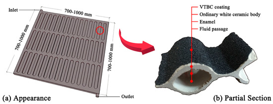
Figure 1.
Appearance and partial section of a typical vanadium-titanium black ceramic (VTBC) solar collector.
Compared with other solar collectors, VTBC solar collectors are roughly equivalent in terms of collection efficiency. For example, based on previous studies, the relationship between collection efficiency (η) and irradiation intensity (I) of a typical VTBC collector, as illustrated above, is shown in Figure 2. However, the efficiencies are not only a function of irradiance but also influenced by other ambient conditions and system designs. A literature review showed that the efficiency values of VTBC collectors obtained under laboratory conditions range from 39% to 65% [15,16,17,18]. Moreover, VTBC collectors have been used in construction projects, such as residences, greenhouses, and educational buildings (Figure 3). Under these practical conditions, the efficiency values range from 24% to 57% [12,19,20,21,22,23]. Among these, more than 80% of the testing results are within the range of 40–50%.
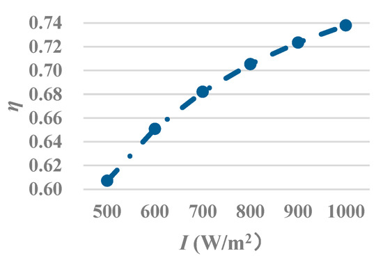
Figure 2.
Dependence between efficiency (η) and irradiation intensity (I) of a typical VTBC solar collector.
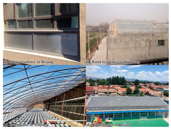
Figure 3.
Construction projects using VTBC collectors.
However, previous studies have mostly focused on the manufacture or application of VTBC collectors, rather than deeply investigating their thermal mechanism [24]. Beyond these studies, Żukowski [25] presented the results of laboratory testing and numerical simulations of VTBC absorbers without considering the effects caused by transparent cover and insulation materials. Ma [26] conducted experiments on the dynamic thermal performance of VTBC collectors under multiple factors but offered no optimization proposal.
To improve the heat-collection efficiency of all-ceramic solar collectors, this paper reports on the will building of a mathematical model of a VTBC solar collector, analyzing its heat-transfer process via theoretical computing. Then, this paper reports on the observed performance of a typical domestic VTBC solar collector via an experimental study. After a sensitivity analysis of the parameters, this paper presents the optimized collector design by varying different parameters individually [27].
2. Theory
The working principle of VTBC solar collectors is similar to that of metal plate collectors. First, part of the solar energy radiates on the absorber through the transparent cover, while the other part is absorbed by the cover or reflected back into the sky. Second, part of the solar energy reaching the absorber is absorbed and converted into thermal energy, while the other part is reflected by the plate back to the cover. Third, the heat transfer fluid flows into the flow passages from the inlet of the collector and is heated by thermal energy. Fourth, after the temperature rises, the fluid medium flows out from the outlet of the collector containing useful thermal energy. In such a heat-transfer cycle, the incident solar radiation energy is gradually stored in heat storage equipment; however, the cover, end walls, and backplate of the collector continuously lose heat to the ambient environment. This cycle proceeds until the absorber temperature reaches a steady-state point [28].
2.1. Energy Conservation Relationship
According to the law of energy conservation, the internal energy increase in the collector per unit time (Qs) is equal to the difference between the solar radiant energy projected onto the aperture surface of the collector (IAa) and the optical loss (Ql,o), heat loss (Ql,h), and useful energy outputted by the collector (Qu) (Equation (1)). In this process, Ql,o includes the optical energy reflected not only by the transparent cover but also by the absorber (Figure 4).
Qs = IAa − Ql,o − Ql,h − Qu = (ṁC)dTabs/dt
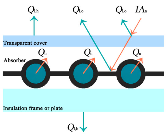
Figure 4.
Energy conservation relationship of VTBC solar collectors.
Under unsteady-state conditions, such as early in the morning, the absorber temperature (Tabs) increases. All components of the collector continuously absorb heat and store energy. When the sun sets in the evening, Tabs drops, and the components of the collector continuously release heat and energy. Under steady-state conditions, Qs is 0. Therefore, for the convenience of analysis, unsteady-state conditions are not considered in this study. At this point, Qu can be expressed by Equation (2).
Qu = IAa − Ql,o − Ql,h = Cpqm (Tf,o − Tf,i)
On the one hand, Ql,o is mainly related to the transmittance of the transparent cover (τ) and the absorptance of the absorber coating (α) [29]. In Equation (3), (τα)e is the effective transmittance–absorptance product for the absorber, which will be further illustrated in Section 2.2.
Ql,o = IAa [1 − (τα)e]
On the other hand, when Tabs is higher than the ambient temperature (Ta), part of the solar radiation energy absorbed by the collector is lost to the environment. Since Tabs is the highest among all parts of the collector, Ql,h can be expressed by the difference between Tabs and Ta (Equation (4)).
Ql,h = AaUL (Tabs − Ta)
2.2. Effective Transmittance-Absorptance Product for the Absorber
Transmittance (τ) relates to the solar radiation energy passing through the transparent cover to the surface of the absorber while absorptance (α) relates to the radiation energy absorbed by the absorber. According to Figure 5 [30], these radiation transmission, absorption, and reflection processes are repeated continuously between the transparent cover and the absorber. The solar radiant energy absorbed by the absorber in this process can be summed, and the transmittance-absorptance product for the absorber (τα) can be calculated using Equation (5). In this equation, τ and α are both measured values. Among these, τ is 90–96% for the commonly used ultraclear tempered glass [31]. This study uses an average value, 93%. In addition, the α value of a VTBC solar collector is 0.94 [24]. The reflectivity of the transparent cover to scattered radiation (ρd) is related to the extinction coefficient (K) and the travel length (L) of solar radiation.
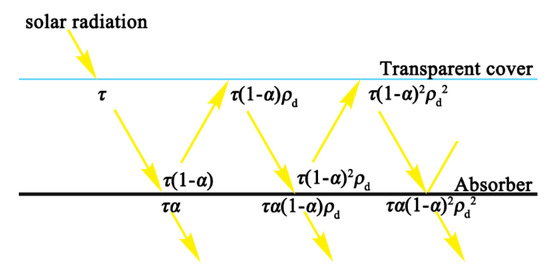
Figure 5.
The processes of radiation transmission, absorption, and reflection in the transparent cov-er-absorber system.
Furthermore, for the whole collector, part of the solar radiation absorbed by the transparent cover is not lost. This is because this part of the energy increases the cover temperature, and so reduces the heat loss transferred from the absorber to the cover. This process equals the increase in τ. The effective transmittance–absorptance product for an absorber ((τα)e) with N layers of transparent covers can be calculated according to Equation (6). Among these, ai is a constant value, as shown in Table 1 [32]. The emissivity of a VTBC surface (εp) is 0.9 [15]. The value of K for a single ultraclear cover is 4/m.

Table 1.
The values of αi.
The value of Li [33] should be calculated according to the thickness of the corresponding cover layer (δc) and the incidence angle of solar radiation (θi) (Equation (7)). For a VTBC solar collector under steady-state outdoor conditions and with a single-layer ultraclear glass cover [34], (τα)e is primarily related to δc. In Equation (8), the values of sinθi and r are 1 and 1.52, respectively.
2.3. Heat Loss Analysis
The total heat loss of a VTBC solar collector (Ql,h) is composed of heat loss via the top (Qt), bottom (Qb), and edge walls (Qe) (Equation (9)–(12), Figure 6) [35].
Ql,h = Qt + Qb +Qe
Qt = AaUt (Tabs−Ta)
Qb = AaUb (Tabs−Ta)
Qe = AaUe (Tabs−Ta)
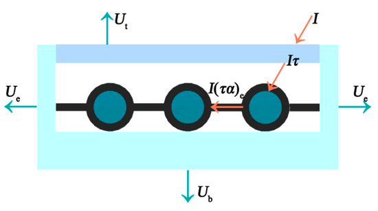
Figure 6.
Total heat loss composition of a VTBC solar collector.
By substituting Equations (9)–(12) into Equation (4), Equation (13) can be obtained [36]. UL, Ut, Ue, and Ub refer to the heat loss coefficient of the total collector, the top, the end walls, and the bottom, respectively.
UL = Ut + Ub + Ue (Ae/Aa)
As shown in Figure 7, to calculate these heat loss coefficients, it is necessary to define the heat transfer process of the collector in operation, which mainly includes (1) the radiative (r) and convective (conv) heat transfer between the outer surface of the transparent cover (c1) and the ambient environment (a); (2) the radiative (r) and convective (conv) heat transfer between the inner surface of the transparent cover (c2) and the absorber (abs); (3) the conductive (cond) heat transfer between the absorber (abs) and the bottom of the collector (b); and (4) the radiative (r) and convective (conv) heat transfer between the bottom (b) and edge walls (e) and the ambient environment (a) [37].
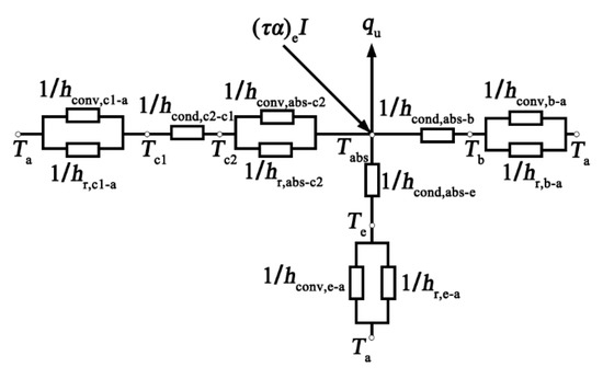
Figure 7.
Thermal network diagram of VTBC solar collector in terms of conduction, convection, and radiation thermal resistance.
Figure 7 can be simplified in terms of the thermal resistance between the two sides (Figure 8). According to this simplified figure, empirical formulas for calculating the heat-loss coefficient at the top of the collector (Ut) are proposed as Equation (14) [38,39,40]. When the average temperature of the hot plate is between Ta and 200 °C, the error of the formulas is no more than 0.3 W/m2K [41].
where
f = (1 + 0.0892hw − 0.1166hwϵp) (1 + 0.07866N)
e = 0.43 (1 − 100/Tabs)
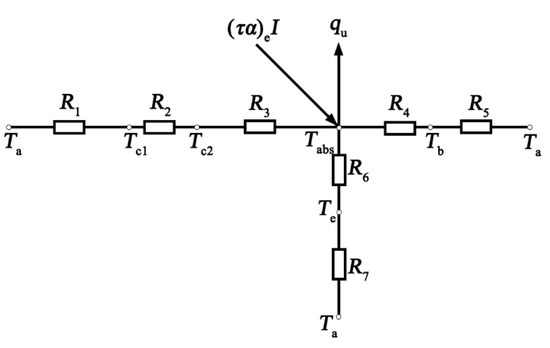
Figure 8.
Thermal network diagram of VTBC solar collector in terms of thermal resistance between the two sides.
The heat loss at the bottom of the collector depends on the thermal resistances R4 of the insulation layer and R5 to the ambient environment. As R4 is much larger than R5, its bottom heat-loss coefficient can be approximately expressed by Ub = λb/δb. The heat loss of the edge walls (Ue) of the collector is relatively small and can be considered 2% of Ut [15].
2.4. Heat-Transfer Analysis
The heat-transfer performance of a VTBC solar collector can be evaluated by its instantaneous efficiency (η) and average efficiency. Key steps for obtaining these parameters are the calculations of the absorber temperature (Tabs) and the mean fluid temperature (Tf).
2.4.1. Efficiency Factor
After calculating the total heat-loss coefficient of the collector (UL) according to Equation (13), Ql,h can be calculated using Equation (4). However, the heat loss and the temperature difference between the collector and the ambient environment (Ta) are proportional, and so the absorber temperature is not easy to determine. Therefore, the practicability of Equation (4) is limited to some extent. In contrast, the inlet (Tf,i) and outlet (Tf,o) fluid temperatures of the collector are easier to measure. Thus, the performance of the collector can also be reflected by Tf,i and Tf,o, as shown in Equation (15) [42].
where
Ql,h = AaF’UL (Tf − Ta)
Tf = 0.5 (Tf,i + Tf,o)
For the VTBC solar collector shown in Figure 1, its efficiency factor (F’) can be calculated according to Equation (16) [43]. The thermal conductivity of the VTBC fin (λabs) is 1.256 W/mK. Therefore, F’ is a physical quantity related to the geometric structure of the collector and is constant for a collector with a certain structure and fluid flow. The F’ of a good flat-plate solar collector is generally 0.9–1.0 [44].
where
hi = (1430 + 23.3Tf − 0.048Tf2) ww0.8Di−0.2
2.4.2. Heat-Removal Factor
After introducing F’, UL can be calculated based on Tf. However, although Tf can be measured, it is not easy to control in actual tests. This is because Tf,o varies with solar conditions. In contrast, Tf,i is easier to measure. Therefore, in this study, UL is defined according to Tf,i. Then, the heat removal factor (FR) of the collector is introduced (Equations (17) and (18)) [45]. FR is a dimensionless parameter that comprehensively reflects the influence of the heat-transfer performane of the collector and the fluid. It is not only related to the geometric structure and heat transfer characteristics of the collector but also affected by the mass flow rate of the fluid (qm), the specific heat capacity of the fluid (Cp), and the aperture area of the collector (Aa).
Ql,h = AaFRUL (Tf,i − Ta)
2.4.3. Absorber Temperature and Mean Fluid Temperature
Then, Tabs and Tf can be obtained according to Equations (19) and (20), respectively [43].
2.4.4. Collection Efficiency
Instantaneous efficiency (η) is the thermal performance of a collector at a specific time and can be expressed as Equation (21) [46,47]. If it is assumed that UL is a constant that does not change with temperature, η can be expressed as Equation (22). When η is 0, Tabs and Tf are equal to Tf,i, which means that the collector reaches its highest operating temperature. This temperature depends mainly on (τα)e and UL. Therefore, increasing (τα)e or decreasing UL are effective ways to improve the operating temperature.
If A = FR (τα)e, B = FRUL, Tm* = (Tf − Ta)/I, then η = A − BTm* [48]. For a given solar collector, A is the intercept efficiency, a constant that mainly depends on the optical characteristics of the transparent cover and the absorber. It represents the highest efficiency that the collector can theoretically achieve. B is the heat loss coefficient based on the inlet temperature and a constant that mainly depends on the collector structure and thermal insulation design. Theoretical analysis and experience show that the thermal performance of a collector can be roughly evaluated when A and B are obtained.
3. Methods
Using the abovementioned mathematical model of VTBC solar collectors, it is possible to conduct an optimization design theoretically by altering some influencing factors. This computation aims to obtain η and evaluate the performance of VTBC solar collectors with certain structures. Based on Equations (21) and (22), UL and other parameters are required when calculating η. According to Equations (9)–(14), UL is a function of Tabs. However, Tabs is not a constant parameter known in advance. Therefore, the calculation of UL should adopt a numerical solution method. The computing method designed in this study assumes Tabs* based on experience at the beginning and calculates it gradually according to the equations above until the calculated Tabs is obtained (Figure 9). If the absolute value of the difference between Tabs* and Tabs is less than 10−6, it can be considered to meet the accuracy requirements [28]. Otherwise, the calculated value is iterated as the second assumed value until Tabs that meets the requirement of precision is obtained. Finally, η of the collector is calculated according to this value. To facilitate and accelerate the iterative computing progress, a computer program was created.
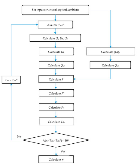
Figure 9.
Flow chart of the computing study.
4. Experimental Study of a Reference Collector
The key to improving the thermal performance of solar collectors lies in increasing (τα)e and reducing UL. For a VTBC solar collector, the absorptance (α) and emissivity (εp) of the absorber are fixed values, while other factors vary according to different collector designs. To observe the performance of a typical domestic VTBC solar collector, the authors conducted an experimental study and analyzed the relationships between the collector performance and the ambient conditions.
4.1. Experimental Setup
A reference VTBC solar collector was designed, tested, and analyzed by the abovementioned mathematical model (Figure 10 and Figure 11 and Table 2) [49]. The experiment was conducted from 9 a.m. to 4 p.m. on 10 to 12 April on the campus of Shandong Jianzhu University in a cold area of China (E: 117.20, N: 36.68). The sampling time interval was 5 min. The inlet fluid temperature (Tf,i) and fluid speed in the passage (Ww) remained constant at 20 °C and 0.707 kg/s, respectively.
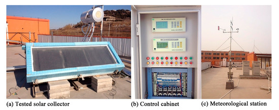
Figure 10.
The tested VTBC solar collector and measurement stand.
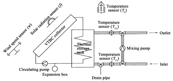
Figure 11.
System diagram for the tested VTBC solar collector.
Table 2.
Input parameters of the reference collector model.
4.2. Experimental Results
Based on the experiment, the dependencies among I, Ta, and Tf,o are illustrated below, although the focus of this paper is to discuss the effects of collector structure design on thermal performance. The trend lines in Figure 12 show that the performance of the tested collector is positively related to I and Ta (Figure 12). On the one hand, with an increase in I, Qu of the collector increases rapidly, which in turn increases η. On the other hand, with an increase in Ta, the temperature difference between Ta and Tabs decreases, Ql,h decreases, and η increases. However, the influence of wind is not great, as the average value of w is only 2.8 m/s. In general, the instantaneous efficiency equation of the testing collector is η = 0.89 − 2.20Tm*.
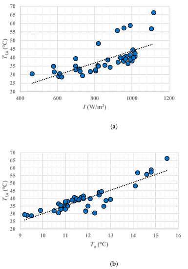
Figure 12.
Dependence between collector performance and ambient conditions. (a) Dependence between Tf,o, and I. (b) Dependence between Tf,o, and Ta.
5. Mathematical Optimization
This section reports on sensitivity analyses of the effects of the design parameters on the performance of the typical VTBC solar collector in order to conduct optimization. The influence of each parameter is shown in the figures below, representing its influence on Tf, Tabs, Ql,h, Ql,o, Qu, F, F’, FR, and η. Although external parameters such as ambient and fluid conditions also have impacts on the performance of the collector, this section focuses on the designs of the fin and the transparent cover. Therefore, in this optimization study, Ta, I, w, Tf,i, and qm still under the average conditions of the above experiment, which are 11.8 °C, 864 W/m2, 2.8 m/s, 20 °C, and 0.0707 kg/s, respectively.
5.1. Influence of Fin Design
For the VTBC solar collector described in Figure 1, the most important design parameters of the fin are width (W) and thickness (δ).
5.1.1. Fin Width
In this scenario, W is the only variable (Figure 13). The value of W is no less than Do, and it has a great influence on the thermal performance of the collector. First, an increase in W increases not only the absorber area parallel to the transparent cover but also the heat-transfer distance to the fluid passage. Because the thermal conductivity of VTBC is poor, Tf shows no clear dependence on W. However, as δ is small and remains unchanged in this scenario, Tabs has a linear relationship with W. Second, W has little effect on Ql,o, but has negative impacts on Ql,o and Qu. Third, although an increase in W also leads to decreases in F, F’, and FR, there is a peak value of η. When W increases from 30 to 50 mm, η increases by 1.55%; when W increases from 50 to 80 mm, η decreases by 9.01%.
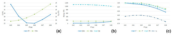
Figure 13.
Influence of W. (a) Dependence between Tf, Tabs, and W. (b) Dependence between energy, and W. (c) Dependence between efficiency parameters, and W.
5.1.2. Fin Thickness
In this scenario, δ was the only variable (Figure 14). First, an increase in δ greatly influenced Tf and Tabs. Second, change in δ had little effect on energy loss and output. Third, overall, F, F’, and FR all increased slightly with an increase of δ, while η hardly changed. This indicates that for the optimal design of a VTBC solar collector, a change in δ does not significantly affect its thermal performance.
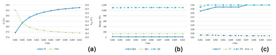
Figure 14.
Influence of δ. (a) Dependence between Tf, Tabs, and δ. (b) Dependence between energy, and δ. (c) Dependence between efficiency parameters, and δ.
5.2. Influence of Transparent Cover Design
For the VTBC solar collector described in Figure 1, the most important design parameters for the transparent cover are number of layers (N), thickness (δc), transmittance (τ), and refractive index (r).
5.2.1. Number of Transparent Layers
In this scenario, N was the only variable (Figure 15). First, with an increase in N, Tf, and Tabs both decreased. The change range of 1 to 2 was much greater than that of 2 to 3. Second, an increase in N had little effect on Ql,h and Qu. Third, N had little influence on F, F’, and FR. Moreover, an increase in N had some effect on (τα)e and η. When N increased from 1 to 2, η increased by 5.17%; however, when N increased from 2 to 3, η decreased by 2.83%. Therefore, N = 2 is the best option for this model.
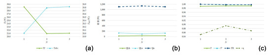
Figure 15.
Influence of the number of layers (N). (a) Dependence between Tf, Tabs, and N. (b) Dependence between energy, and N. (c) Dependence between efficiency parameters, and N.
5.2.2. Thickness of the Transparent Cover
In this scenario, δc was the only variable (Figure 16). First, when δc increased, Tf and Tabs both increased. Second, δc has little effect on energy loss and output. Third, δc has little effect on F, F’, and FR but had some positive effect on η. When δc increased from 3 to 12 mm, η increased by 1.82%. In general, increasing δc had little effect on the performance of the collector.
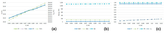
Figure 16.
Influence of the transparent cover thickness (δc). (a) Dependence between Tf, Tabs, and δc. (b) Dependence between energy, and δc. (c) Dependence between efficiency parameters, and δc.
5.2.3. Transmittance of the Transparent Cover
In this scenario, τ was the only variable (Figure 17). First, Tf and Tabs increased linearly with τ. Second, Ql,h was not affected by τ, while Ql,o and Qu were. Third, τ had little influence on F, F’, and FR, but has a great influence on η. Based on a literature review, for ultraclear glass τ can be as large as 0.96 [50,51]. When τ increased from 0.82 to 0.96, η increased by 17.42%. Therefore, the use of a transparent cover with a high τ is crucial for collection efficiency.
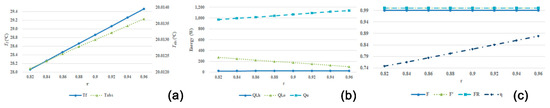
Figure 17.
Influence of transparent cover transmittance (τ). (a) Dependence between Tf, Tabs, and τ. (b) Dependence between energy, and τ. (c) Dependence between efficiency parameters, and τ.
5.2.4. Refractive Index of the Transparent Cover
In this scenario, r was the only variable (Figure 18). From the perspective of transparent cover materials, the average r values of organic materials, ordinary glass materials, and transparent plastic materials were approximately 1.49, 1.52, and 1.59, respectively [52]. Increasing r had a slightly negative effect on Tabs and η but had almost no effect on the other indicators. In general, the effect of r on collector performance was not great.
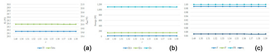
Figure 18.
Influence of transparent cover refractive index (r). (a) Dependence between Tf, Tabs, and r. (b) Dependence between energy, and r. (c) Dependence between efficiency parameters, and r.
5.3. Optimization Results
Effective ways to improve the efficiency of the VTBC solar collector were to increase τ, N, and δc. Among these, the most useful and low-cost method was to use a transparent cover with a high τ (Table 3). Therefore, this study increased τ to 0.96 individually by replacing the normal glass cover with an ultraclear glass cover. According to the calculation results, the instantaneous efficiency equation of the optimization model was η = 0.92 − 2.20Tm*.
Table 3.
Sensitivity analyses of τ, N, and δc.
6. Discussion
The thermal performance of solar collectors is also affected by external factors, which include ambient conditions (Ta, I, and w) and system situations (Tf,i, qm, and Aa). Among these, the latter are more controllable in system operation. In Figure 19a, Tf,i was the only variable. For this optimization model, Tf,i has an optimum value (approximately 20 °C). With a continuous increase in Tf,i, Tabs also increased. Therefore, the temperature difference between Tabs and Ta increased, which led to an increase in Ql,h, and a decrease in η. In Figure 19b, qm was the only variable. Tf and Tabs decreased as qm increased but gradually became stable. Although an increase in qm did not affect Ql,o, it had a small positive effect on Ql,h and η. When qm increased from 0.03 kg/s to 0.10 kg/s, η increased by 3.97%. In Figure 19c, Aa is the only variable. As qm remained unchanged when Aa continues to increase; the working medium cannot transfer the heat absorbed to the outlet in a timely manner, resulting in more energy loss. That is, the higher the Aa is, the lower the η. In this scenario, when Aa increased from 1 to 8 m2, η decreased by 7.52%. Although these parameters can influence the performance of the VTBC collector, their effects were far smaller than that of the collector’s structural design.
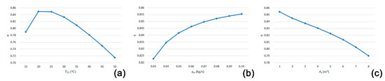
Figure 19.
Influence of system situations. (a) Dependence between Tf,i, and η. (b) Dependence between qm, and η. (c) Dependence between Aa, and η.
7. Conclusions
From theoretical and experimental points of view, this paper has analyzed the heat-transfer process and thermal performance of VTBC solar collectors and optimized the collector design according to the effects of different parameters. First, in terms of heat-transfer analysis, the performance of VTBC solar collectors can be evaluated by factors such as F’, FR, and η. Although the analysis theories are similar to those for traditional metal flat-plate solar collectors, ceramic materials have unique characteristics. On the one hand, the VTBC coating has both high absorptance (α = 0.94) and high emissivity (εp = 90%). On the other hand, the thermal conductivity of VTBC is very low (λabs = 1.256 W/mK). Second, in terms of optimization, this paper set up a thermal-performance calculation method under steady-state conditions and a corresponding computer program. Via experimental testing, this study has proposed a reference model (η = 0.89 − 2.20Tm*). Then, the study has analyzed the influence of fin design and transparent cover design on the collector using the mathematical model and varied the most sensitive parameter τ individually to create the optimization model (η = 0.92 − 2.20Tm*).
This paper presents a fast and low-cost method to optimize VTBC collector design under steady-state conditions based on mathematical modeling. In future studies, more work should be done to verify the accuracy of the model via optimized absorber manufacturing and corresponding experimental testing under unsteady-state conditions.
Author Contributions
Conceptualization, D.D.; methodology, D.D.; validation, W.H.; formal analysis, D.D.; investigation, D.D. and W.H.; resources, D.D.; data curation, W.H.; writing—original draft preparation, D.D.; writing—review and editing, D.D. and C.L.; visualization, D.D.; supervision, C.L.; project administration, D.D.; funding acquisition, D.D. and W.H. All authors have read and agreed to the published version of the manuscript.
Funding
This work was funded by the National Natural Science Foundation of China (51778350) and (52078281) and Xihua University (Z202040).
Institutional Review Board Statement
Not applicable.
Informed Consent Statement
Not applicable.
Acknowledgments
The authors acknowledge the support of Dingxin Zhang of Shandong Sheyu Architectural Design Consulting Co. Ltd. for the software implementation in this work.
Conflicts of Interest
The authors declare no conflict of interest. The funders had no role in the design of the study; in the collection, analyses, or interpretation of data; in the writing of the manuscript, or in the decision to publish the results.
Nomenclature
| Symbol | Definition |
| Aa | Aperture area of the collector (m2) |
| Ae | Area of the collector edge walls |
| Cp | Specific heat capacity of the fluid (J/kgK) |
| Di | Inner diameter of the passage (m) |
| Do | Outer diameter of the passage (m) |
| F | Fin efficiency |
| FR | Heat-removal factor |
| F’ | Efficiency factor |
| hi | Convective heat-transfer coefficient inside the passage (W/m2K) |
| hw | Convective heat-transfer coefficient between the transparent cover and ambient environment (W/m2 K) |
| Ki | Extinction coefficient of tier i transparent cover (1/m) |
| l | Length of the collector (m) |
| Li | Optical path length of solar radiation travel in tier i (m) |
| ṁC | Heat capacity of the collector (J/K) |
| N | Number of transparent layers |
| I | Solar irradiation intensity on the aperture surface of the collector (W/m2) |
| ρd | Reflectivity of the transparent cover to scattered radiation |
| Qb | Heat loss via the collector bottom (W) |
| Qe | Heat loss via the collector edge walls (W) |
| Ql,h | Total heat loss of the collector (W) |
| Ql,o | Optical loss of the collector (W) |
| Qt | Heat loss via the collector top (W) |
| qm | Mass flow rate of the fluid (kg/s) |
| Qs | Internal energy increase in the collector in energy per unit time (W) |
| Qu | Useful energy output by the collector (W) |
| r | Refractive index of the transparent cover |
| t | Time (s) |
| Ta | Ambient temperature (°C) |
| Tabs | Absorber temperature (°C) |
| Tabs* | Assumed absorber temperature (°C) |
| Tf | Mean fluid temperature (°C) |
| Tf,i | Inlet fluid temperature (°C) |
| Tf,o | Outlet fluid temperature (°C) |
| Ub | Heat-loss coefficient of the collector bottom (W/m2 K) |
| Ue | Heat-loss coefficient of the collector edge walls (W/m2 K) |
| UL | Total heat-loss coefficient of the collector (W/m2 K) |
| Ut | Heat-loss coefficient of the collector top (W/m2 K) |
| W | Fin width; the distance between adjacent passages’ axes (m) |
| w | Wind speed (m/s) |
| Ww | Fluid speed in the passage (kg/s) |
| α | Absorptance of the absorber |
| δ | Fin thickness (m) |
| δb | Thickness of the insulation layer at the bottom of the collector (m) |
| δc | Thickness of the transparent cover layer (m) |
| εc | Emissivity of the transparent cover |
| εp | Emissivity of the absorber |
| η | Instantaneous efficiency of the collector |
| θi | Incidence angle of solar radiation (°) |
| λabs | Thermal conductivity of the fin (W/mK) |
| λb | Thermal conductivity of the insulation material at the bottom of the collector (W/mK) |
| σ | Stefan Boltzmann constant (5.67 × 10⁻⁸ W/m2K4) |
| ρw | Density of the fluid (kg/m3) |
| τ | Transmittance of the transparent cover |
| τi | Transmittance of the tier (i + 1) transparent cover |
| (τα) | Transmittance–absorptance product for the absorber |
| (τα)e | Effective transmittance–absorptance product for the absorber |
| φ | Inclination angle of the collector (°) |
References
- Zhao, J.; Ji, Y.; Yuan, Y.; Zhang, Z.; Lu, J. Seven operation modes and simulation models of solar heating system with PCM storage tank. Energies 2017, 10, 2128. [Google Scholar] [CrossRef]
- Gomaa, M.R.; Mustafa, R.J.; Rezk, H.; Al-Dhaifallah, M.; Al-Salaymeh, A. Sizing methodology of a multi-mirror solar concentrated hybrid PV/thermal system. Energies 2018, 11, 3276. [Google Scholar] [CrossRef]
- Papadimitratos, A.; Sobhansarbandi, S.; Pozdin, V.; Zakhidov, A.; Hassanipour, F. Evacuated tube solar collectors integrated with phase change materials. Sol. Energy 2016, 129, 10–19. [Google Scholar] [CrossRef]
- Zhao, C.; You, S.; Wei, L.; Gao, H.; Yu, W. Theoretical and experimental study of the heat transfer inside a horizontal evacuated tube. Sol. Energy 2016, 132, 363–372. [Google Scholar] [CrossRef]
- Bracamonte, J.; Parada, J.; Dimas, J.; Baritto, M. Effect of the collector tilt angle on thermal efficiency and stratification of passive water in glass evacuated tube solar water heater. Appl. Energy 2015, 155, 648–659. [Google Scholar] [CrossRef]
- Bhowmik, H.; Amin, R. Efficiency improvement of flat plate solar collector using reflector. Energy Rep. 2017, 3, 119–123. [Google Scholar] [CrossRef]
- Wang, R.Z.; Zhai, X.Q. Development of solar thermal technologies in China. Energy 2010, 35, 4407–4416. [Google Scholar] [CrossRef]
- Colmenar-Santos, A.; Vale-Vale, J.; Borge-Diez, D.; Requena-Pérez, R. Solar thermal systems for high rise buildings with high consumption demand: Case study for a 5 star hotel in Sao Paulo, Brazil. Energy Build. 2014, 69, 481–489. [Google Scholar] [CrossRef]
- Yang, Y.; Wang, Q.; Xiu, D.; Zhao, Z.; Sun, Q. A building integrated solar collector: All-ceramic solar collector. Energy Build. 2013, 62, 15–17. [Google Scholar] [CrossRef]
- Wazwaz, A.; Al-Salaymeh, A. Photothermal testing before and after degradation of nickel-pigmented aluminium oxide selective absorber prepared by alternate and reverse periodic plating technique. Energy Convers. Manag. 2013, 65, 770–776. [Google Scholar] [CrossRef]
- Carlsson, B.; Möller, K.; Frei, U.; Brunold, S.; Köhl, M. Comparison between predicted and actually observed in-service degradation of a nickel pigmented anodized aluminum absorber coating for solar DHW systems. Sol. Energy Mater. Sol. Cells 2000, 61, 223–238. [Google Scholar] [CrossRef]
- Sun, X.; Sun, X.; Li, X.; Wang, Z.; He, J.; Wang, B. Performance and building integration of all-ceramic solar collectors. Energy Build. 2014, 75, 176–180. [Google Scholar] [CrossRef]
- Xu, J.; Zhang, X.; Yang, Y.; Liu, B.; Zhang, Y.; Lv, X.; Wei, L.; Wang, X.; Ma, L.; Wang, J. A perspective of all-ceramic solar collectors. Energy Environ. Focus 2016, 5, 1–6. [Google Scholar] [CrossRef]
- Zheng, D.; Wan, D.; Yi, S. Determining the thermal conductivity of ceramic coatings by relative method. Int. J. Appl. Ceram. Technol. 2019, 16, 2299–2305. [Google Scholar] [CrossRef]
- Liu, J. Analysis of thermal performance for a new-type flat-plate collector of black ceramic. J. Gansu Sci. 1990, 2, 12–18. (In Chinese) [Google Scholar]
- Xiu, D.; Cao, S.; Xu, J.; Cai, B.; Wang, Q.; Yang, Y. Application of ceramic solar plate heating system. Shandong Sci. 2013, 26, 72–77. (In Chinese) [Google Scholar]
- He, W. Thermal Performance of Dual-Effect Ceramic Solar Collector and Integrated Building Design; Tianjin University: Tianjin, China, 2014. (In Chinese) [Google Scholar]
- Zukowski, M.; Woroniak, G. Experimental testing of ceramic solar collectors. Sol. Energy 2017, 146, 532–542. [Google Scholar] [CrossRef]
- Ren, C. Ceramic Collection Hot Plate Solar Collector Performance Analysis; Hebei University of Engineering: Handan, China, 2013. [Google Scholar]
- Yang, Y.; Xu, J.; Cai, B.; Wang, Q.; Xiu, D.; Zhao, Z.; Sun, Q.; Cao, S. Synthesis and applications of black ceramic from recycled industrial wastes. Adv. Appl. Ceram. 2013, 112, 146–148. [Google Scholar] [CrossRef]
- Ma, R.; Liu, Q. Project of using V-Ti black porcelain solar energy concentrating and reusing titanium dioxide waste acid. Water Wastewater Eng. 2014, 4, 58–61. (In Chinese) [Google Scholar]
- Yan, J.; Qiao, J. Application of ceramic solar water heating system in the alpine region. J. Qinghai Univ. (Nat. Sci. Ed.) 2014, 32, 34–37. (In Chinese) [Google Scholar] [CrossRef]
- Ding, D. Mechanism and Optimization Design of Vi-Ti Black Ceramic Solar Collecting Technologies Utilized in Rural Residence; Shandong Jianzhu University: Jinan, China, 2018. (In Chinese) [Google Scholar]
- Yang, Y.; Cao, S.; Xu, J.; Cai, B. All-ceramic solar collectors. Ceram. Int. 2013, 39, 6009–6012. [Google Scholar] [CrossRef]
- Żukowski, M.; Woroniak, G.; Piotrowska-Woroniak, J. Experimental research and numerical simulations of a ceramic panel used for solar energy conversion. Sol. Energy 2019, 194, 27–36. [Google Scholar] [CrossRef]
- Ma, R.; Ma, D.; Long, E. Experimental study on the dynamic thermal performance of V-Ti black ceramic solar collector under multiple factors. Sol. Energy 2020, 201, 615–620. [Google Scholar] [CrossRef]
- Demirpolat, A.B. Investigation of mass transfer with different models in a solar energy food-drying system. Energies 2019, 12, 3447. [Google Scholar] [CrossRef]
- Gao, T. Heat Transfer Analysis and Design Optimization of Flat Solar Collector; Tianjin University: Tianjin, China, 2011. (In Chinese) [Google Scholar]
- Herrando, M.; Markides, C.N.; Hellgardt, K. A UK-based assessment of hybrid PV and solar-thermal systems for domestic heating and power: System performance. Appl. Energy 2014, 122, 288–309. [Google Scholar] [CrossRef]
- Wong, I.L.; Eames, P. A method for calculating the solar transmittance, absorptance and reflectance of a transparent insulation system. Sol. Energy 2015, 111, 418–425. [Google Scholar] [CrossRef][Green Version]
- Al Shehri, A.; Parrott, B.; Carrasco, P.; Al Saiari, H.; Taie, I. Impact of dust deposition and brush-based dry cleaning on glass transmittance for PV modules applications. Sol. Energy 2016, 135, 317–324. [Google Scholar] [CrossRef]
- Zhang, H. Solar Thermal Utilization Principle and Computer Simulation, 2nd ed.; Zhang, H., Yu, J., Zhao, C., Jiang, H., Dai, Y., Eds.; Northwestern Polytechnical University Press: Xi’an, China, 2004; (In Chinese). ISBN 7561217447. [Google Scholar]
- Wojcicki, D.J. Derivation of the effective beam radiation incidence angle equations for diffuse and reflected solar radiation using a two dimensional approach. Sol. Energy 2015, 112, 272–281. [Google Scholar] [CrossRef]
- Nakamura, T.; Tsutsumi, N.; Juni, N.; Fujii, H. Thin-film waveguiding mode light extraction in organic electroluminescent device using high refractive index substrate. J. Appl. Phys. 2005, 97, 054505.1–054505.6. [Google Scholar] [CrossRef]
- Liang, R.B.; Zhang, J.L.; Zhao, L.; Ma, L.D. Performance enhancement of filled-type solar collector with U-tube. J. Cent. S. Univ. 2015, 22, 1124–1131. [Google Scholar] [CrossRef]
- Ahmed, O.K.; Bawa, S.M. The combined effect of nanofluid and reflective mirrors on the performance of PV/Thermal solar collector. Therm. Sci. 2019, 23, 573–587. [Google Scholar] [CrossRef]
- Lomascolo, M.; Colangelo, G.; Milanese, M.; De Risi, A. Review of heat transfer in nanofluids: Conductive, convective and radiative experimental results. Renew. Sustain. Energy Rev. 2015, 43, 1182–1198. [Google Scholar] [CrossRef]
- Agarwal, V.K.; Larson, D.C. Calculation of the top loss coefficient of a flat-plate collector. Sol. Energy 1981, 27, 69–71. [Google Scholar] [CrossRef]
- Mahboub, C.; Moummi, N. Calculation of the glass cover temperature and the top heat loss coefficient for 60° vee corrugated solar collectors with single glazing. Sol. Energy 2012, 86, 804–808. [Google Scholar] [CrossRef]
- Helvaci, H.U.; Khan, Z.A. Mathematical modelling and simulation of multiphase flow in a flat plate solar energy collector. Energy Convers. Manag. 2015, 106, 139–150. [Google Scholar] [CrossRef]
- Wagner, T.J.W.; Eisenman, I. False alarms: How early warning signals falsely predict abrupt sea ice loss. Geophys. Res. Lett. 2015, 42, 333–341. [Google Scholar] [CrossRef]
- Zanchini, E.; Jahanbin, A. Simple equations to evaluate the mean fluid temperature of double-U-tube borehole heat exchangers. Appl. Energy 2018, 231, 320–330. [Google Scholar] [CrossRef]
- Shojaeizadeh, E.; Veysi, F.; Kamandi, A. Exergy efficiency investigation and optimization of an Al2O3-water nanofluid based flat-plate solar collector. Energy Build. 2015, 101, 12–23. [Google Scholar] [CrossRef]
- Moss, R.W.; Shire, G.S.F.; Henshall, P.; Eames, P.C.; Arya, F.; Hyde, T. Design and fabrication of a hydroformed absorber for an evacuated flat plate solar collector. Appl. Therm. Eng. 2018, 138, 456–464. [Google Scholar] [CrossRef]
- Lunde, P.J. New heat transfer factors for flat plate solar collectors. Sol. Energy 1981, 27, 109–113. [Google Scholar] [CrossRef]
- Kang, W.; Shin, Y.; Cho, H. Economic analysis of flat-plate and U-tube solar collectors using an Al2O3 nanofluid. Energies 2017, 10, 1911. [Google Scholar] [CrossRef]
- Furbo, S.; Dragsted, J.; Perers, B.; Andersen, E.; Bava, F.; Pagh, K. Yearly thermal performances of solar heating plants in Denmark—Measured and calculated. Sol. Energy 2018, 159, 186–196. [Google Scholar] [CrossRef]
- Gao, D.; Gao, G.; Cao, J.; Zhong, S.; Ren, X.; Dabwan, Y.N.; Hu, M.; Jiao, D.; Kwan, T.H.; Pei, G. Experimental and numerical analysis of an efficiently optimized evacuated flat plate solar collector under medium temperature. Appl. Energy 2020, 269, 115129. [Google Scholar] [CrossRef]
- Hao, W.; Liu, S.; Mi, B.; Lai, Y. Mathematical modeling and performance analysis of a new hybrid solar dryer of lemon slices for controlling drying temperature. Energies 2020, 13, 350. [Google Scholar] [CrossRef]
- Jiang, H.; Zhou, L.; Zhao, H. Effect of Titania on optical properties of ultra clear glasses. Glass Enamel 2013, 41, 21–23. [Google Scholar] [CrossRef]
- Geng, T.; Hu, J.; Wei, C.; Sheng, J.; Qin, L. Review on improving the transmittance of photovoltaic glass. Bull. Chin. Ceram. Soc. 2017, 36, 1594–1598. [Google Scholar]
- Apriyanto, H.; Ravet, G.; Bernal, O.D.; Cattoen, M.; Seat, H.C.; Chavagnac, V.; Surre, F.; Sharp, J.H. Comprehensive Modeling of Multimode Fiber Sensors for Refractive Index Measurement and Experimental Validation. Sci. Rep. 2018, 8, 1–13. [Google Scholar] [CrossRef]
Publisher’s Note: MDPI stays neutral with regard to jurisdictional claims in published maps and institutional affiliations. |
© 2021 by the authors. Licensee MDPI, Basel, Switzerland. This article is an open access article distributed under the terms and conditions of the Creative Commons Attribution (CC BY) license (http://creativecommons.org/licenses/by/4.0/).