
Heat Transfer Characteristics of Thermoelectric Generator System for Waste Heat Recovery from a Billet Casting Process: Experimental and Numerical Analysis


Abstract
1. Introduction
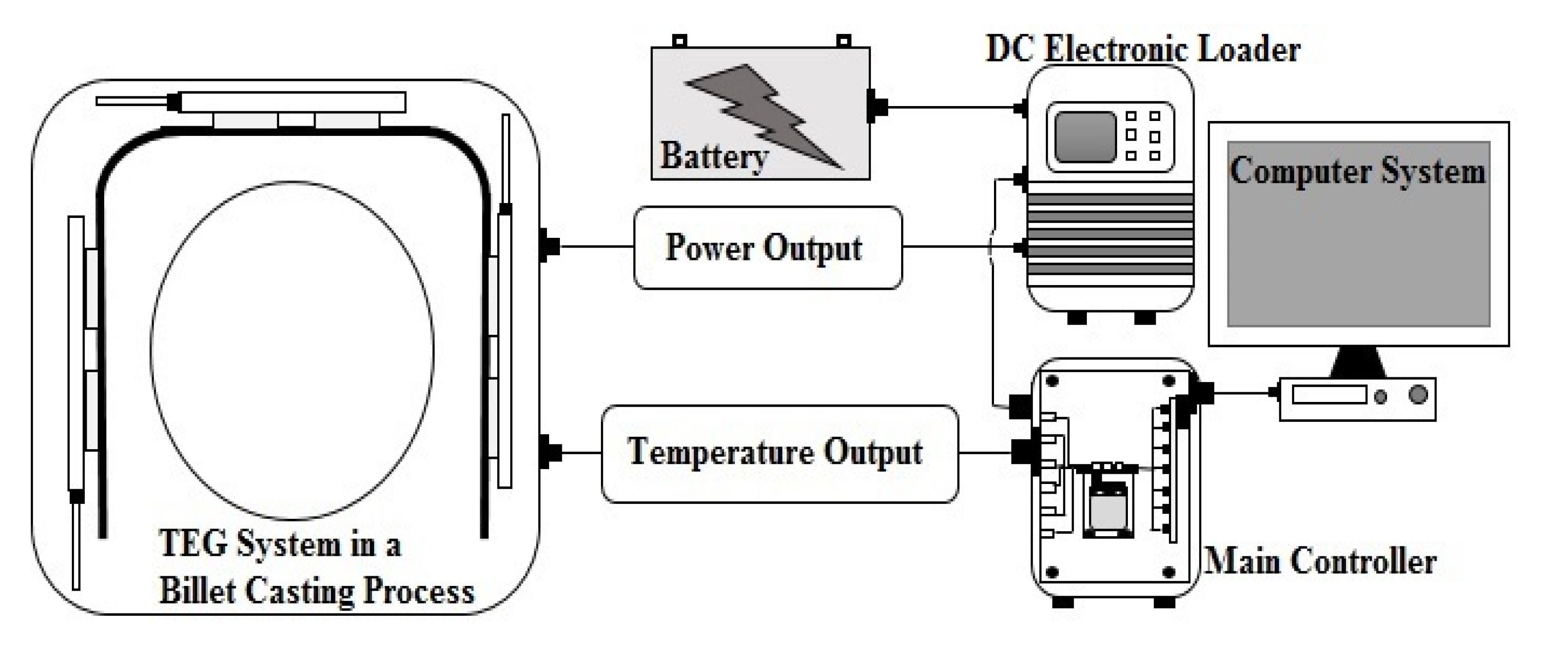
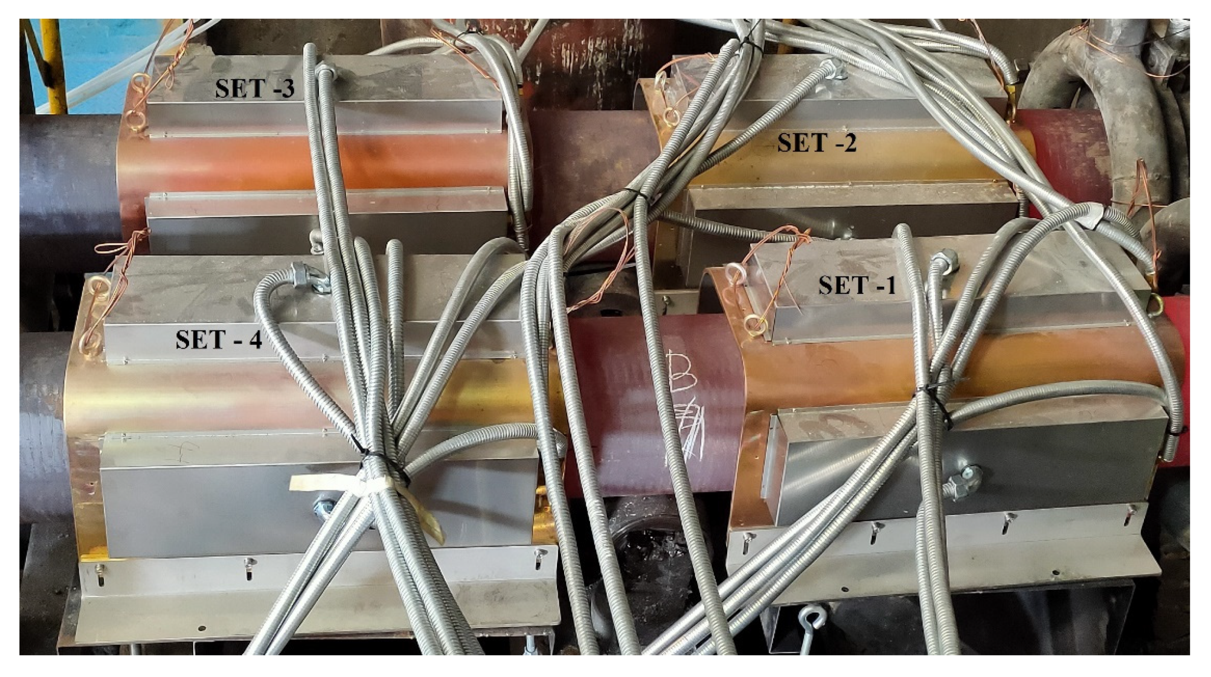
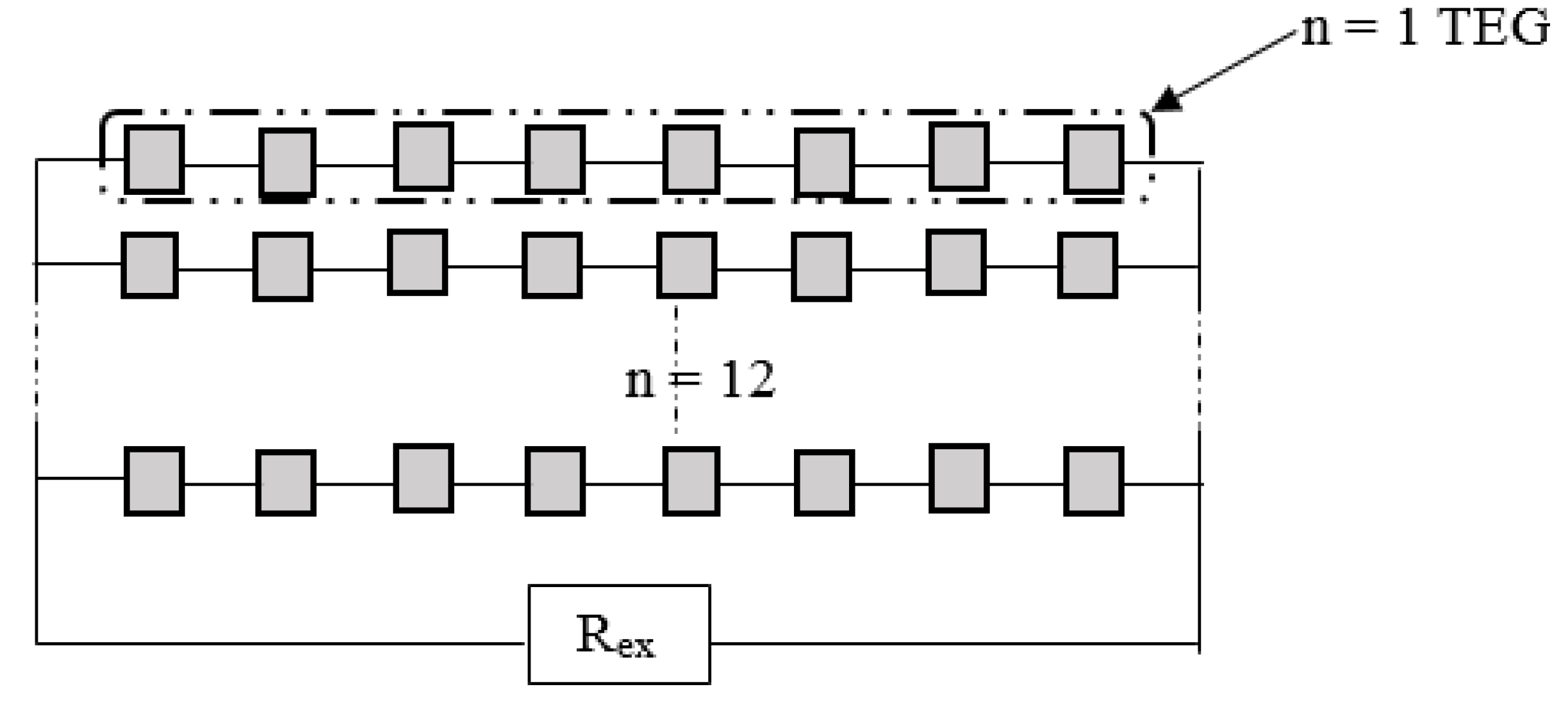
2. Experimental Test Facility and Procedure
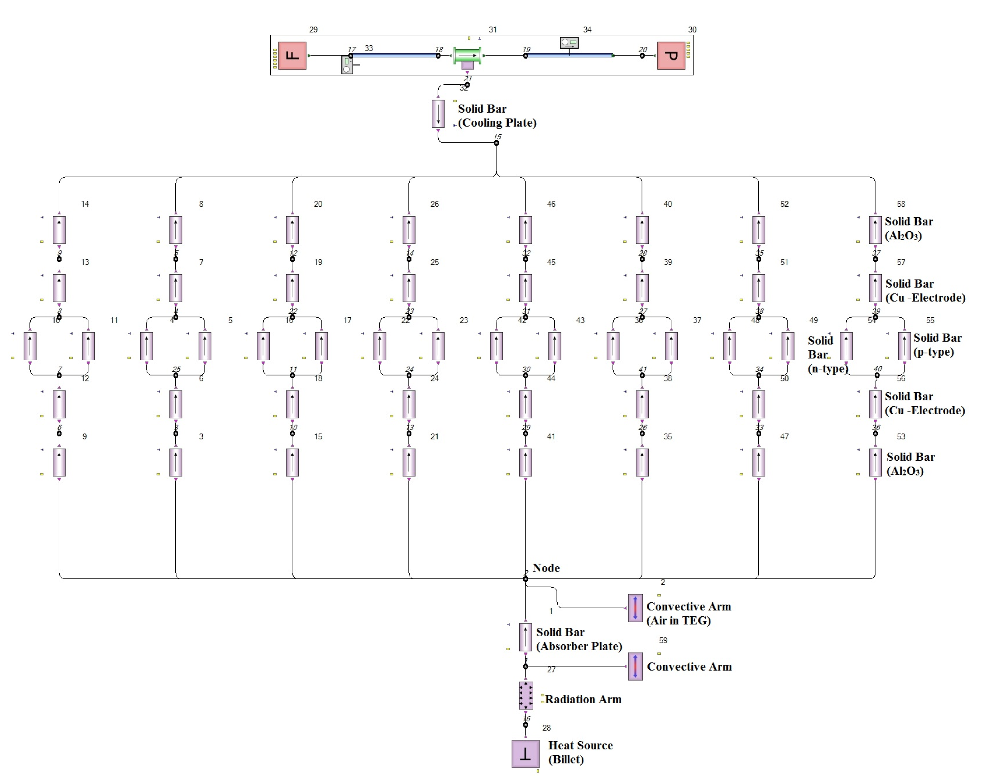
3. One-Dimensional Numerical Study
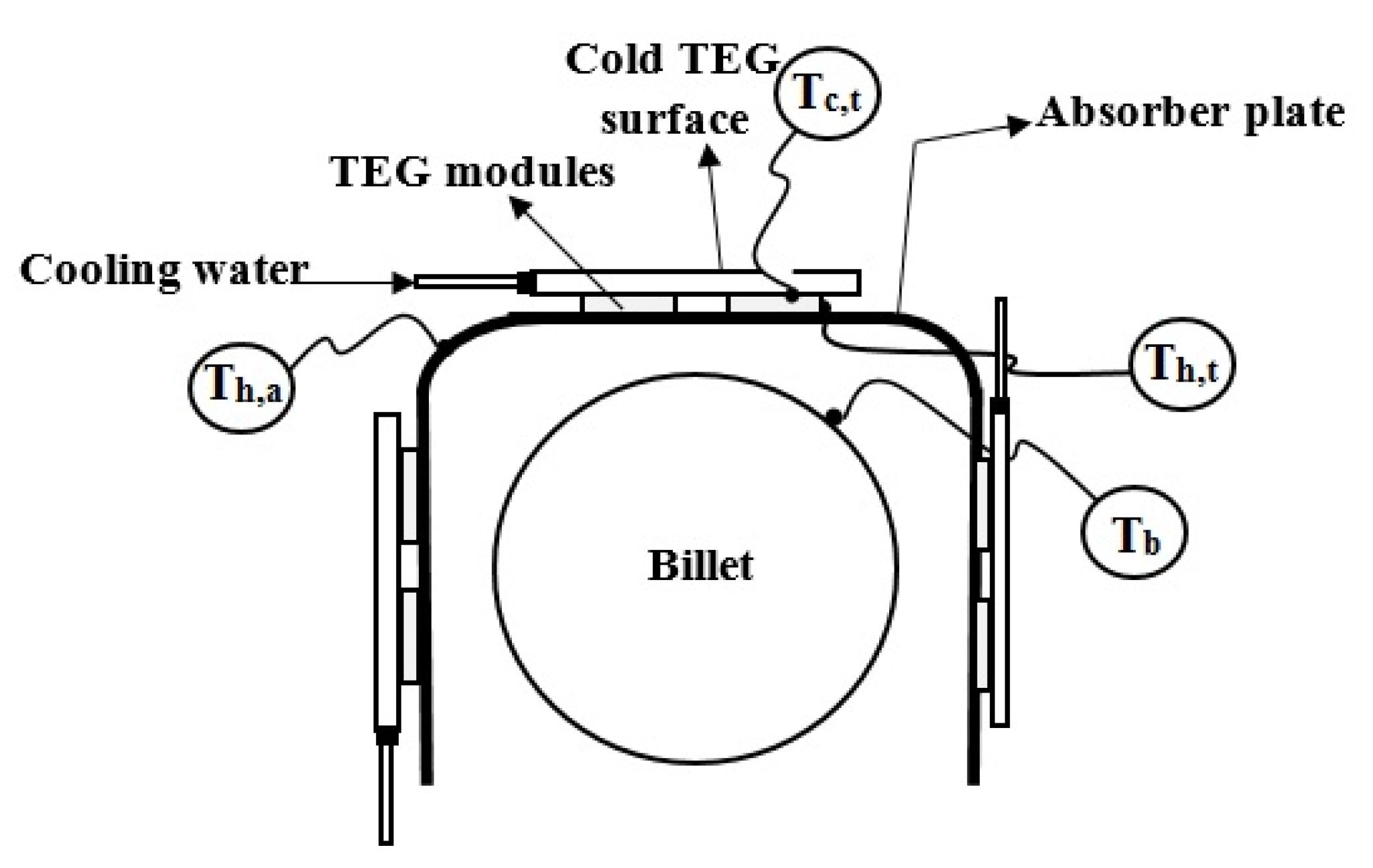
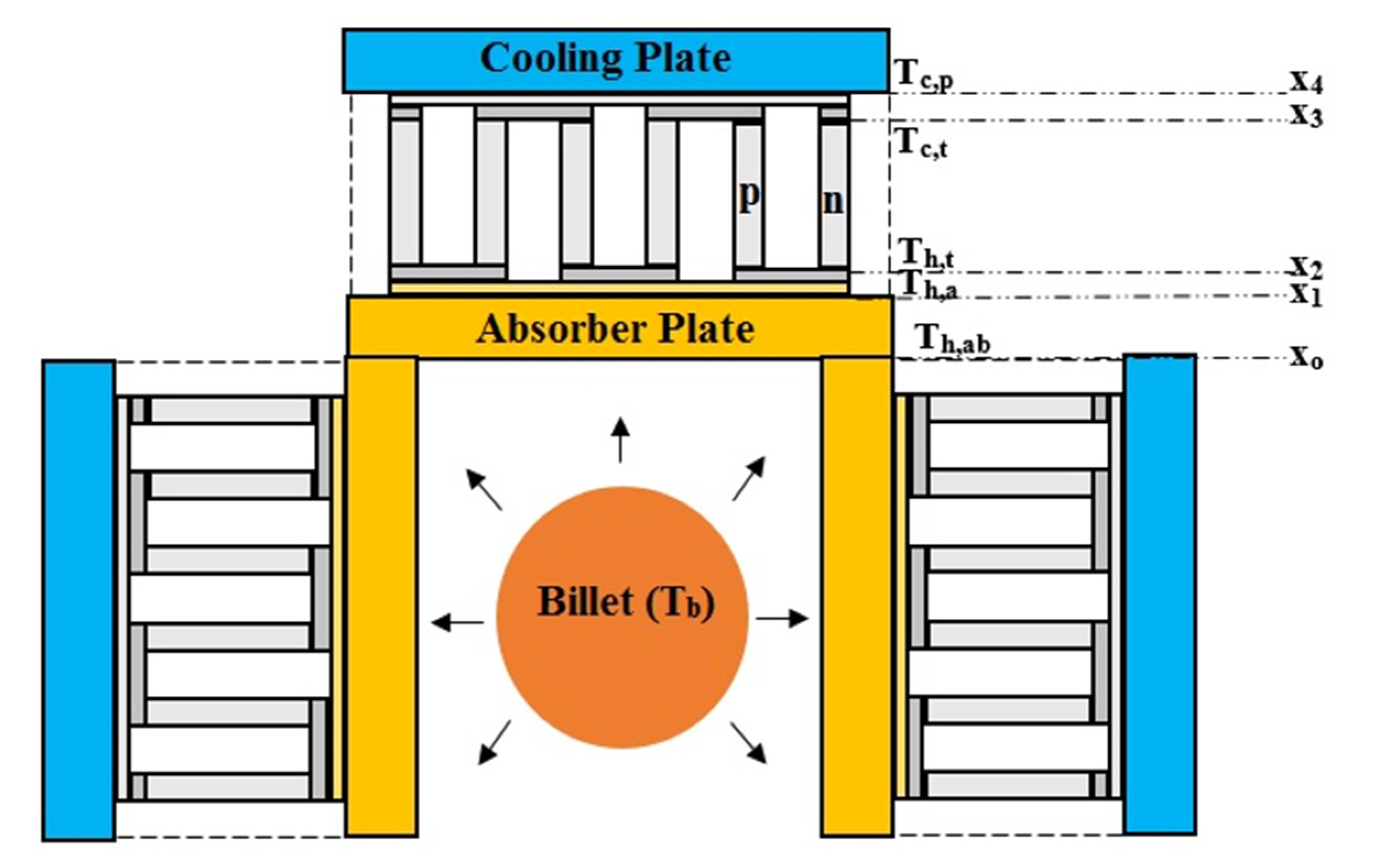
3.1. Boundary Condition
3.2. Transport Equations
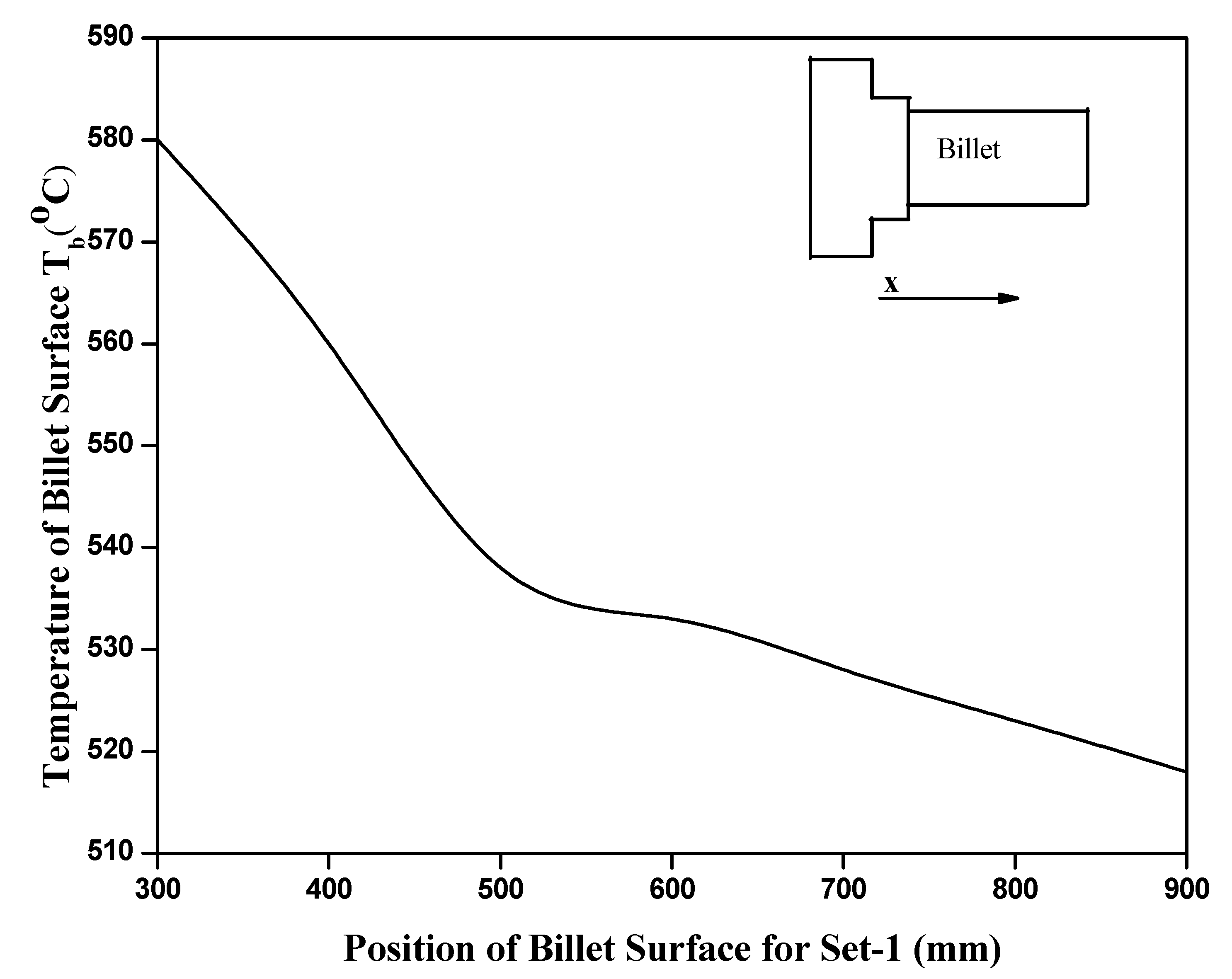
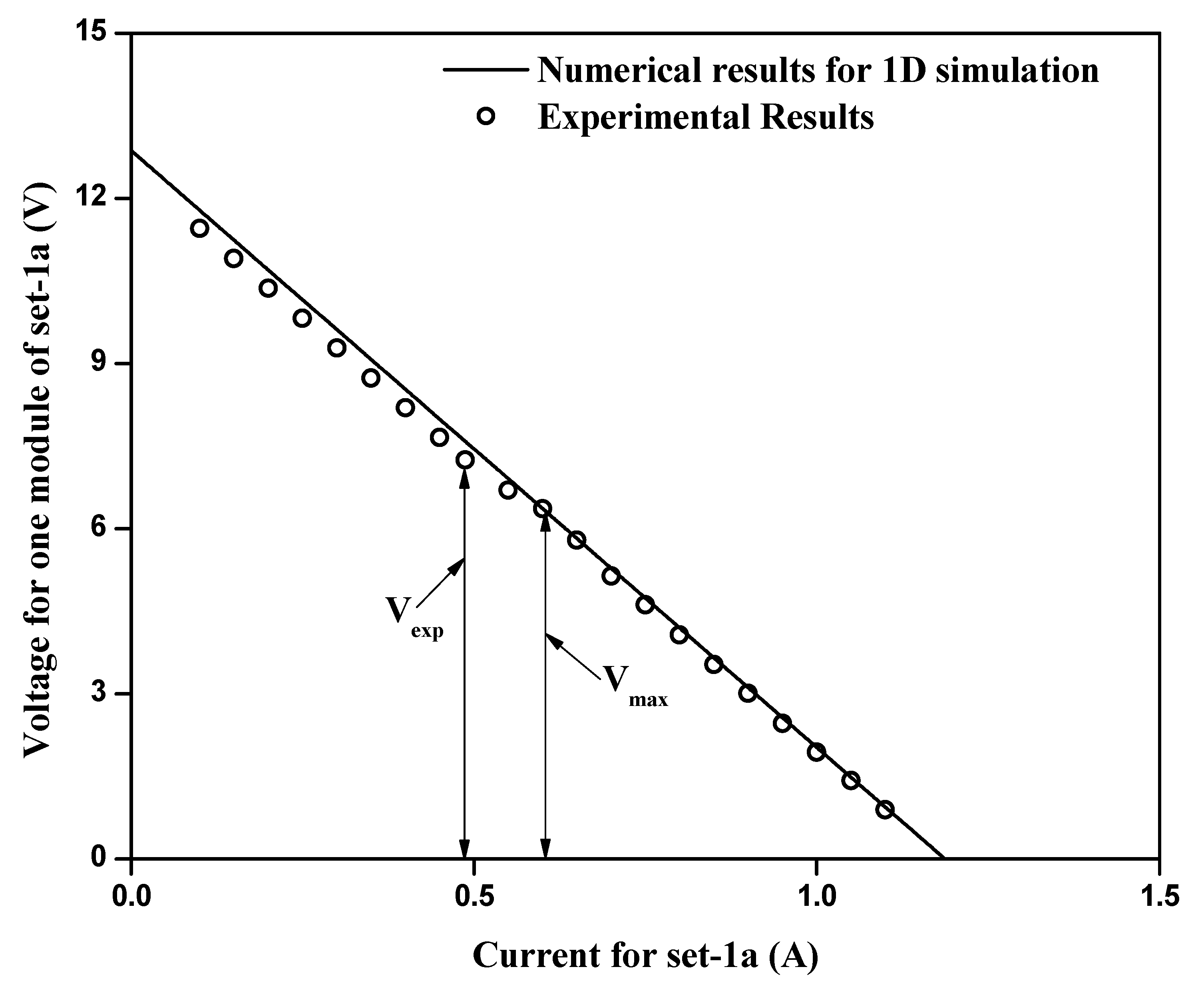
4. Results and Discussion
5. Conclusions
Author Contributions
Funding
Institutional Review Board Statement
Informed Consent Statement
Data Availability Statement
Acknowledgments
Conflicts of Interest
Abbreviation
| Nomenclatures | |
| A | Area [m2] |
| D | Diameter [m] |
| DC | Direct current [a] |
| H | Height [m] |
| h | Heat transfer coefficient [W/m2-K] |
| I | Current [a] |
| K | Conductivity [W/m-K] |
| L | Length [m] |
| Mass flow rate [kg/s] | |
| P | Power [W] |
| Q | Heat flux [W/m2] |
| R | Resistance [Ω] |
| T | Temperature [°C] |
| TEG | Thermoelectric generator [-] |
| U | Overall heat transfer coefficient [W/m2-K] |
| V | Voltage [V] |
| W | Width [m] |
| Greek Symboles | |
| α | Seebeck coefficient [μV/K] |
| ε | Emissivity [-] |
| σ | Stefan-Boltzmann constant [W/m2-K4] |
| η | Efficiency [-] |
| Subscripts | |
| a | Absorber plate (TEG side) |
| ab | Absorber plate (billet side) |
| Avg | Average |
| b | Billet |
| c | Cold |
| cp | Cooling plate |
| c,t | Cold-side TEG |
| cw | Cold water |
| ex | External |
| exp | Experimental |
| h | Hot |
| h,t | Hot-side TEG |
| m | Module |
| max | Maximum |
| pn | p- and n-type semiconductors |
References
- Jaziri, N.; Boughamoura, A.; Müller, J.; Mezghani, B.; Tounsi, F.; Ismail, M. A comprehensive review of Thermoelectric Generators: Technologies and common applications. Energy Rep. 2020, 6, 264–287. [Google Scholar] [CrossRef]
- Daniel, C. Thermoelectric generators: A review of applications. Energy Convers. Manag. 2017, 140, 167–181. [Google Scholar]
- Forman, C.; Muritala, I.K.; Pardemann, R.; Meyer, B. Estimating the global waste heat potential. Renew. Sustain. Energy Rev. 2016, 57, 1568–1579. [Google Scholar] [CrossRef]
- Firth, A.; Zhang, B.; Yang, A. Quantification of global waste heat and its environmental effects. Appl. Energy 2019, 235, 1314–1334. [Google Scholar] [CrossRef]
- Huang, F.; Zheng, J.; Baleynaud, J.M.; Lu, J. Heat recovery potentials and technologies in industrial zones. J. Energy Inst. 2017, 90, 951–961. [Google Scholar] [CrossRef]
- Jouhara, H.; Khordehgah, N.; Almahmoud, S.; Delpech, B.; Chauhan, A.; Tassou, S.A. Waste heat recovery technologies and applications. Therm. Sci. Eng. Prog. 2018, 6, 268–289. [Google Scholar] [CrossRef]
- Kaibe, H.; Makino, K.; Kajihara, T.; Fujimoto, S.; Hachiuma, H. Thermoelectric generating system attached to a carburizing furnace at Komatsu Ltd., Awazu Plant. AIP Conf. Proc. 2012, 1449, 524–527. [Google Scholar]
- Aranguren, P.; Astrain, D.; Pérez, M.G. Computational and experimental study of a complete heat dissipation system using water as heat carrier placed on a thermoelectric generator. Energy 2014, 74, 346–358. [Google Scholar] [CrossRef]
- Aranguren, P.; Astrain, D.; Rodriguez, A.; Martinez, A. Experimental investigation of the applicability of a thermoelectric generator to recover waste heat from a combustion chamber. Appl. Energy 2015, 152, 121–130. [Google Scholar] [CrossRef]
- Kuroki, T.; Murai, R.; Makino, K.; Nagano, K.; Kajihara, T.; Kaibe, H.; Hachiuma, H.; Matsuno, H. Research and development for thermoelectric generation technology using waste heat from steelmaking process. J. Electron. Mater. 2015, 44, 2151–2156. [Google Scholar] [CrossRef]
- Kuroki, T.; Kabeya, K.; Makino, K.; Kajihara, T.; Kaibe, H.; Hachiuma, H.; Matsuno, H.; Fujibayashi, A. Thermoelectric generation using waste heat in steel works. J. Electron. Mater. 2014, 43, 2405–2410. [Google Scholar] [CrossRef]
- Kajihara, T.; Makino, K.; Lee, Y.H.; Kaibe, H.; Hachiuma, H. Study of thermoelectric generation unit for radiant waste heat. Mater. Today Proc. 2015, 2, 804–813. [Google Scholar] [CrossRef]
- Ebling, D.G.; Krumm, A.; Pfeiffelmann, B.; Gottschald, J.; Bruchmann, J.; Benim, A.C.; Adam, M.; Labs, R.; Herbertz, R.R.; Stunz, A. Development of a system for thermoelectric heat recovery from stationary industrial processes. J. Electron. Mater. 2016, 45, 3433–3439. [Google Scholar] [CrossRef]
- Yazawa, K.; Shakouri, A.; Hendricks, T.J. Thermoelectric heat recovery from glass melt processes. Energy 2017, 118, 1035–1043. [Google Scholar] [CrossRef]
- Luo, Q.; Li, P.; Cai, L.; Zhou, P.; Tang, D.; Zhai, P.; Zhang, Q. A thermoelectric waste-heat-recovery system for Portland cement rotary kilns. J. Electron. Mater. 2015, 44, 1750–1762. [Google Scholar] [CrossRef]
- Jang, J.Y.; Tsai, Y.C.; Wu, C.W. A study of 3-D numerical simulation and comparison with experimental results on turbulent flow of venting flue gas using thermoelectric generator modules and plate fin heat sink. Energy 2013, 53, 270–281. [Google Scholar] [CrossRef]
- Børset, M.T.; Wilhelmsen, Ø.; Kjelstrup, S.; Burheim, O.S. Exploring the potential for waste heat recovery during metal casting with thermoelectric generators: On-site experiments and mathematical modelling. Energy 2017, 118, 865–875. [Google Scholar] [CrossRef]
- Cao, Q.; Luan, W.; Wang, T. Performance enhancement of heat pipes assisted thermoelectric generator for automobile exhaust heat recovery. Appl. Therm. Eng. 2018, 120, 1472–1479. [Google Scholar] [CrossRef]
- Remeli, M.F.; Date, A.; Orr, B.; Ding, L.C.; Singh, B.; Affandi, N.D.N.; Akbarzadeh, A. Experimental investigation of combined heat recovery and power generation using a heat pipe assisted thermoelectric generator system. Energy Convers. Manag. 2016, 111, 147–157. [Google Scholar] [CrossRef]
- Kang, J.O.; Kim, S.C. Heat Transfer Characteristics of Heat Exchangers for Waste Heat Recovery from a Billet Casting Process. Energies 2019, 12, 2695. [Google Scholar] [CrossRef]


| Module Specification | Material | Size (L × W × H) mm3 |
|---|---|---|
| Insulator | Ceramic (Al2O3) | 60 × 60 × 1 |
| Electrode | Copper (C1100) | 3.7 × 1.6 × 0.3 |
| Semiconductor | Bi2Te3 | 1.5 × 1.5 × 0.3 |
| Properties | Ceramic | Copper | p–Type | n–Type |
|---|---|---|---|---|
| Thermal conductivity (W/mK) | 25 | 387.5 | 1.3 | 1.1 |
| Electrical resistivity (10−5 Ωm) | - | - | 4.1 | 3.7 |
| Seebeck coefficient (μV/K) | - | - | 203.7 | −172.1 |
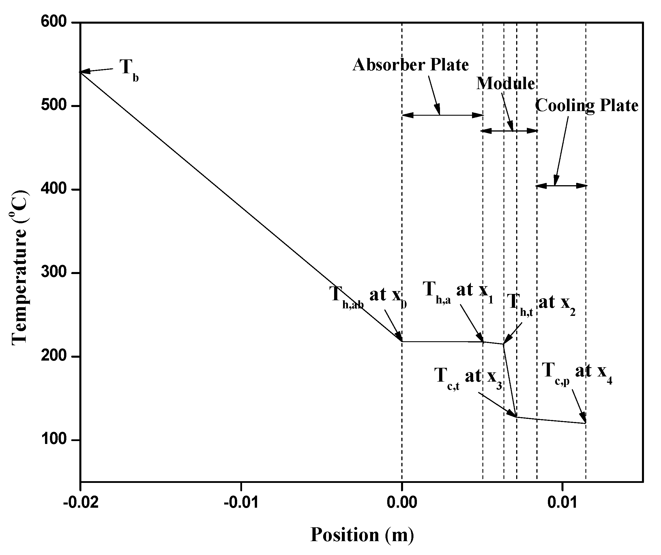
| TEG Set No. | (Tb)avg in (°C) | (Th,t)TEG in (°C) | (Tc,t)TEG in (°C) | (∆T)TEG in (°C) | Theoretical Power of one Module for Battery Rated Voltage (W) | Percentage Variation of Power with Set-1a (%) |
|---|---|---|---|---|---|---|
| 1a | 540.0 | 207.5 | 122.2 | 85.3 | 3.533 | 0 |
| 1b | 206.1 | 121.0 | 85.1 | 3.518 | −0.424 | |
| 1c | 206.6 | 121.6 | 85.0 | 3.511 | −0.623 | |
| 2a | 543.2 | 212.8 | 126.7 | 86.1 | 3.611 | 2.207 |
| 2b | 210.5 | 124.6 | 85.9 | 3.590 | 1.613 | |
| 2c | 209.1 | 123.3 | 85.8 | 3.583 | 1.415 | |
| 3a | 512.6 | 194.6 | 109.8 | 84.8 | 3.483 | −1.415 |
| 3b | 193.4 | 108.9 | 84.5 | 3.454 | −2.236 | |
| 3c | 193.9 | 108.3 | 84.6 | 3.462 | −2.009 | |
| 4a | 509.3 | 192.4 | 107.9 | 84.5 | 3.454 | −2.236 |
| 4b | 192.1 | 107.8 | 84.3 | 3.432 | −2.859 | |
| 4c | 191.4 | 107.3 | 84.1 | 3.414 | −3.368 |
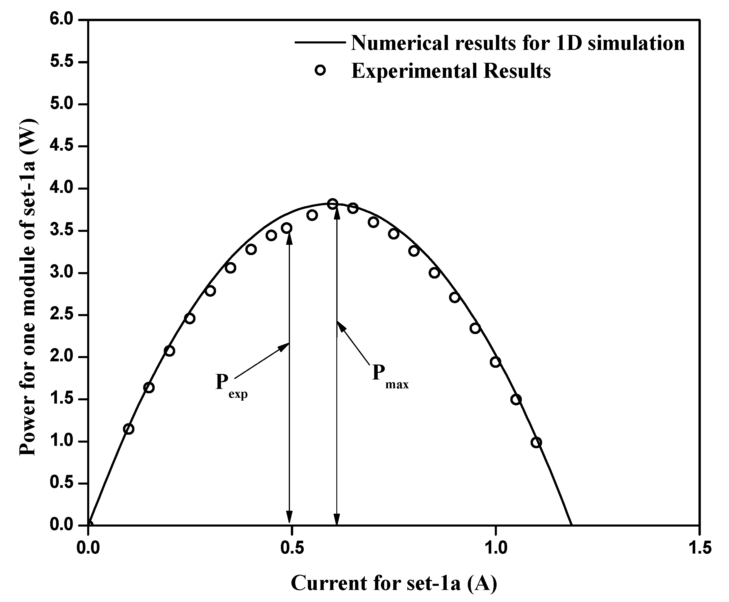
| Parameter | Experimental Result | Numerical Result | Variation (%) |
|---|---|---|---|
| Hot-side TEG temperature (°C) | 207.5 | 215.3 | 3.62 |
| Cold-side TEG temperature (°C) | 122.2 | 127.7 | 4.31 |
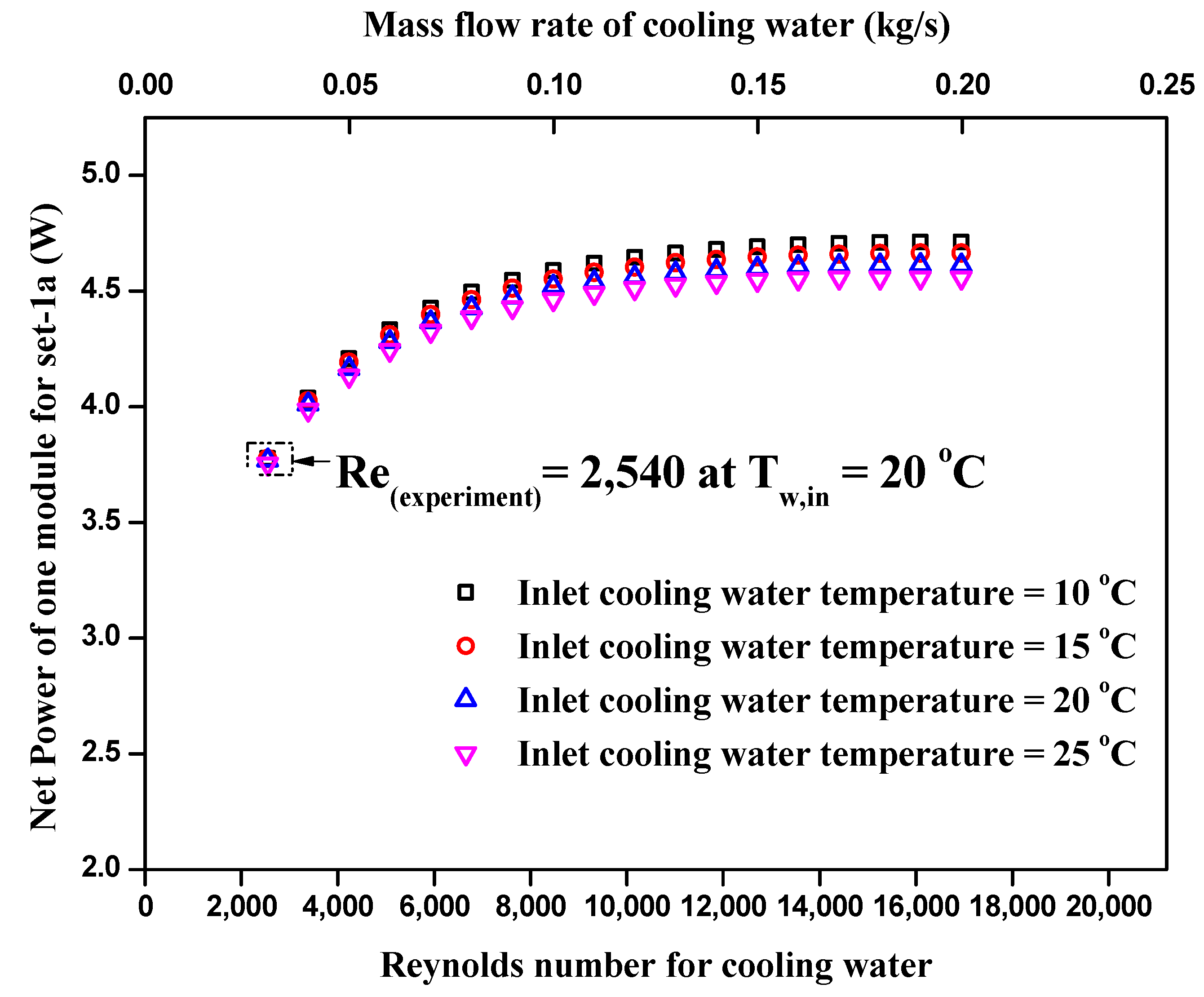
| Power produced by one module of set-1a (W) | 3.53 | 3.7 | 4.59 |
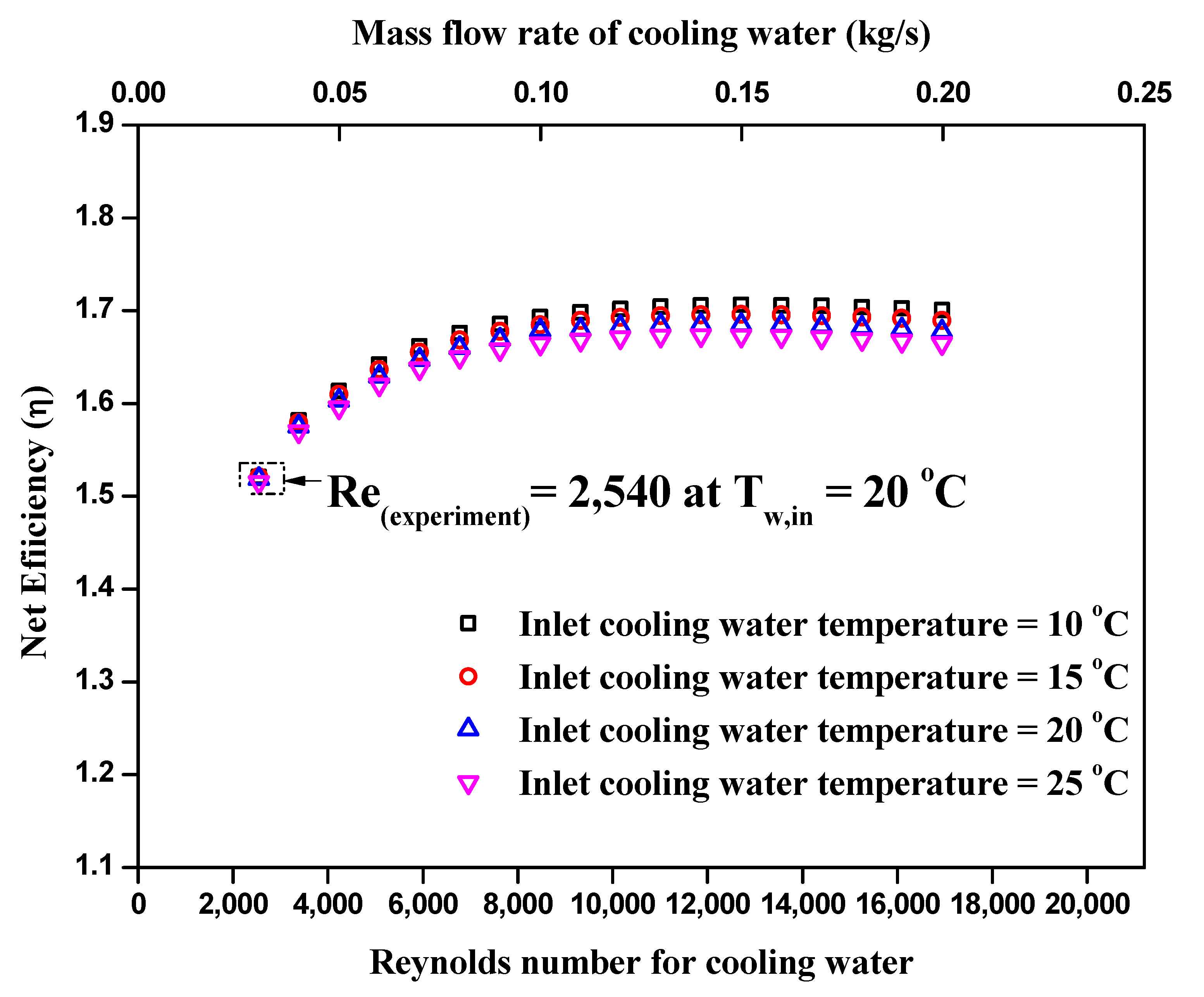
| Efficiency of one TEG module for set-1a (%) | 1.48 | 1.5 | 1.34 |
Publisher’s Note: MDPI stays neutral with regard to jurisdictional claims in published maps and institutional affiliations. |
© 2021 by the authors. Licensee MDPI, Basel, Switzerland. This article is an open access article distributed under the terms and conditions of the Creative Commons Attribution (CC BY) license (http://creativecommons.org/licenses/by/4.0/).
Share and Cite
Yadav, S.; Liu, J.; Kong, M.S.; Yoon, Y.G.; Kim, S.C. Heat Transfer Characteristics of Thermoelectric Generator System for Waste Heat Recovery from a Billet Casting Process: Experimental and Numerical Analysis. Energies 2021, 14, 601. https://doi.org/10.3390/en14030601
Yadav S, Liu J, Kong MS, Yoon YG, Kim SC. Heat Transfer Characteristics of Thermoelectric Generator System for Waste Heat Recovery from a Billet Casting Process: Experimental and Numerical Analysis. Energies. 2021; 14(3):601. https://doi.org/10.3390/en14030601
Chicago/Turabian StyleYadav, Saurabh, Jie Liu, Man Sik Kong, Young Gyoon Yoon, and Sung Chul Kim. 2021. "Heat Transfer Characteristics of Thermoelectric Generator System for Waste Heat Recovery from a Billet Casting Process: Experimental and Numerical Analysis" Energies 14, no. 3: 601. https://doi.org/10.3390/en14030601
APA StyleYadav, S., Liu, J., Kong, M. S., Yoon, Y. G., & Kim, S. C. (2021). Heat Transfer Characteristics of Thermoelectric Generator System for Waste Heat Recovery from a Billet Casting Process: Experimental and Numerical Analysis. Energies, 14(3), 601. https://doi.org/10.3390/en14030601