Abstract
This study presents a combined cooling, heating, and power system powered by biogas, suitable for small scale communities in remote locations. To run such a system, in order to obtain the daily life essentials of electricity, hot water, and cooling, municipal waste can be considered as an option. Furthermore, the organic Rankine cycle part of the organic Rankine cycle powered vapor compression chiller can be used in times of need for additional electric production. The system comprises a medium temperature organic Rankine cycle utilizing M-xylene as its working fluid, and the cooling was covered by an Isobutane vapor compression cycle powered by an R245fa employing organic Rankine cycle. The system analyzed was designated to provide 250 kW of electricity. The energetic and exergetic analysis was performed, considering several system design parameters. The impact of the design parameters in the prime mover has a much greater effect on the whole system. The system proposed can deliver cooling values at the rate between 9.19 and 22 kW and heating values ranging from 879 up to 1255 kW, depending on the design parameter. Furthermore, the second law efficiency of the system was found to be approximately 56% at the baseline conditions and can be increased to 64.5%.
1. Introduction
In contemporary times, the world is faced with two critical challenges of the rising population with increasing energy demands and the need to meet the sustainable energy goals set by the Paris Agreement towards mitigating the effect of global warming. If the world’s energy policy is not changed, then with energy demand continual expected rise of 1.3% each year until 2040 [1], will result in even more serious outcomes owing to the greenhouse gas emissions. Surprisingly, there is a huge gap between the promises of energy for all, with nearly one billion people without access to electricity. This gap necessitates rapid, proactive solutions to ebb global greenhouse gas emissions, highlighting the need for possible renewable-driven energy shifts [1,2]. The incorporation of renewable energy becomes more important, particularly as the economies of several nations is improving [3]. From several renewable energy sources available, biomass is considered to be the most viable option as it generates enough heat for stable functioning in comparison with the wind, solar, and hydro sources, or it is constraint by location like geothermal [4,5,6,7].
Furthermore, to utilize the full potential of the biomass renewable energy sources, trigeneration, commonly attributed as combined cooling, heating, and power (CCHP) [8], can be employed. That is because trigeneration offers better performance as it enables the utilization of waste heat for heating and cooling purposes. Most CCHP systems can be deployed as decentralized facilities such as in local district energy systems (LES) to serve the local demand for heating, cooling as well as electricity in a more efficient way [8]. Moreover, as it offers efficient onsite production of electricity, heating, and cooling at a reduced fuel and energy costs, it results in significant reductions of greenhouse gas emissions [9].
The prime mover of the trigeneration system is the most important part of the system [10]. The most common types of prime movers for the thermally actuated trigeneration systems are the internal combustion engines, gas turbines, organic Rankine cycles (ORCs), Stirling engines, fuel cells, microgas turbines, or steam turbines [11]. In some instances, several parallel prime movers have also been used, such as in the case of system suggested by Figaj et al. [12], which used steam Rankine cycle and wind turbines in parallel as prime movers. Alternatively, sometimes additional external auxiliary systems to cover the demands are linked with the prime mover to cover the demands, such as the system, proposed by Calsie et al. [13]. Amongst the prime movers, the ORC holds the capacity to use renewable energy at comparatively lower temperatures [14]. It is a technology based on the Rankine cycle technology that uses the organic compounds as its working fluids, which owing to their lower normal boiling point, can harness energy from low temperature heat sources [15]. Furthermore, the organic compounds, used as ORC working fluids, could be dry or isentropic; that is, their saturated vapor entropy curve on the temperature-entropy diagram could be positive or infinite. Unlike water, which is a wet working fluid exhibiting a negative saturated vapor entropy curve on the temperature–entropy line, requiring superheating, the dry and isentropic working fluids do not require superheating. Therefore, no superheating equipment, which tends to be greater in size owing to the reduced heat transfer coefficient of the vapor phase, is required [16]. Apart from it, the application of working fluids representing higher vapor densities than water can be used in order to achieve a relatively lower pressure drop in heat exchangers and smaller expander sizes [16].
Owing to such attributes of the ORC, there have been several studies available displaying ORC as the prime mover of biomass powered CCHP system. Regarding ORC as the prime mover of a biomass CCHP system for a relatively small scale, Jradi and Riffat [17] performed experimental studies on a system that used Potassium formate liquid desiccant cooler and reported energetic efficiency of approximately 84.4%. Their system was able to provide heating, cooling, and electric power of around 9.6 kW, 6.5 kW, and 500 W. Moreover, Karellas and Braimakis [18] performed the thermal and economic analysis of a biomass-solar ORC coupled vapor compression chiller (VCC) system to provide the CCHP utilities for a residential complex considering Greek climactic conditions and reported nominal exergetic efficiency and a payback period of 7.56% and 7 years, respectively. Their proposed system was reported to be capable of delivering cooling, heating, and power values of around 5, 53.5, and 1.4 kW respectively. The nominal energetic and exergetic values were observed to be 5.54% and 7.56%, respectively. Additionally, Navarro-Esbrí et al. [19] performed analysis for a biomass powered commercial R245fa ORC having absorption chiller to provide the CCHP provisions to a supermarket located in Spain, and reported a saving of approximately 285 tons of CO2/year. Moreover, Wang et al. [20] performed a thermal, economic, and environmental analysis of an ORC primed CCHP system equipped with R134a/Dimethyl formyl/Helium Diffusion absorption refrigeration cycle for a small house located in Anhui, China. Their system achieved energetic efficiency, the summer quarter cost saving, and the CO2 emission reduction of 55.26%, RMB 3121.40, and 0.15 tons, respectively. Apart from it, Bellos et al. [21] conducted thermal, economic, and environmental analysis of a solar and biomass powered ORC-VCC system considering the weather conditions of Greece. The annual energy and exergy efficiency were found to be 51.26% and 21.77%, respectively. Meanwhile, the payback period and the annual CO2 reduction were observed to be around 5.13 years and 125 tons, respectively.
Meanwhile, regarding a relatively larger scale, Huang et al. [22] conducted a thermal and economic analysis of a biomass powered R245fa ORC primed CCHP system that used an absorption chiller to provide cooling. The system designed was mentioned to be capable of delivering 204 kW of electricity, 972 kW of heating, and 226 kW of cooling. The thermal efficiency of their proposed system was found to be approximately 71.7% at the breakeven electricity selling price of 103 £/kWh. Additionally, Amirante et al. [23] performed the energetic and economic analysis of an MDM working fluid ORC primed CCHP system with an absorption chiller for the cooling utilities to cover the utilities of a cluster of buildings of the Bari airport, located in Italy. The energetic efficiencies in the CCP and CHP modes were said to be 71.8% and 31.2%, respectively. Whereas the payback period and the CO2 savings were disclosed to be 6 years and 1176 t/year, respectively. In addition to it, Ahmadi et al. [24] performed the thermal analysis of a biomass powered ORC primed system that was reported to deliver nominal electricity of 350 kW, heating of 1644 kW, and cooling of around 2000 kW. Apart from it, their proposed system also delivered hydrogen and freshwater. Double effect LiBr-water absorption chiller bottoming the ORC was reported to deliver an exergetic efficiency of approximately in the range from 32% to 34%. Apart from them, Al-Sulaiman et al. [25] conducted the exergetic and environmental analysis of an n-octane ORC primed and a single effect chiller and reported exergetic efficiency of around 27% and a noticeable reduction in the CO2 emission values. Other than this, Mouaky and Rachek [26] performed the thermoeconomic analysis of an ORC primed system that used the heat energy from the solar as well as the biomass energy. The space cooling was considered to be provided by a VCC that was powered by the electricity produced by the ORC, while the heating demand was fulfilled using the condenser waste heat. The analysis was conducted considering the needs of a 40 household community situated in the Benguerir, Morocco. Their system displayed the overall energetic and exergetic efficiencies having values of 8.25% and 3.89%, respectively. Furthermore, it was also shown that by using R1336mzz(Z) in place of R245fa could ebb the biomass consumption by approximately 13.4%.
From the open literature review, it has been observed by the authors that in most of the instances, the absorption refrigeration technologies comprised the system to handle the cooling demands. Other than this, the application of ejector refrigeration technologies for providing cooling utilities has also been analyzed on several occasions. For instance, Boyaghchi and Chavoshi [27] analyzed a system that incorporated an ejector cycle within an ORC cycle. The system proposed by them was powered by solar and geothermal heat sources. From their analysis, R134a was declared the best working fluid showing 4.194% daily exergetic efficiency. Furthermore, Boyaghchi et al. [28] for the same system proposed by them in [27] predicted R1234yf as the best working fluid with the minimum product cost rate of 5267.91 USDs/year. Bellos and Tzivanidis [29] for the same system and reported that the system could deliver electrical, cooling, and heating capacities of 4.6, 7.1, and 59.4 kW, respectively. The energetic and the exergetic efficiencies were found to be around 11.26% and 87.39%. Apart from it, as already mentioned above, the vapor compression technology partly driven directly by the ORC prime mover has also been used, as presented in [18,21,30,31].
Moreover, from the conducted literature review, there have been very few instances where ORC as the prime mover for the CCHP system has been used, especially to provide the cooling, heating, and the power utilities for a small-scale community. Apart from it, the utilization of the ORC-VCC as the bottoming cycle, to the best of authors’ knowledge, has never been analyzed. The advantage of using ORC-VCC in comparison to the absorption chiller is that they can be used for electricity production in case of low or cooling demand [15,32]. Therefore, in this article, as a first step, the thermal performance of the proposed relatively compact novel system for supplying multienergy streams for a small-scale community was evaluated. The impact of the selected parameters of the ORC and VCC on the exergetic performance of the trigeneration systems was evaluated and presented. As the VCC and the ORCs are somewhat matured technologies, in the authors’ opinion, such a system or its slight modification shall be easy to establish in the developing or underdeveloped countries.
2. System Description
The schematic of the system under consideration is mentioned below in Figure 1. The system consists of a medium temperature ORC, responsible for providing electricity and heat for the domestic water heating, and a relatively lower temperature ORC-VCC to provide the cooling and provide heating for domestic hot water.
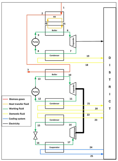
Figure 1.
Schematic of the proposed biomass hybrid trigeneration system.
For the medium temperature ORC, m-xylene was selected as the working fluid. M-xylene was deemed an appropriate candidate for the medium temperature ORC based on the thermal and economic performance indices of Aziz et al. [33]. The heat source temperature in the range 230–650 °C, is classified as the medium temperature energy source by a report available online by the United States Department of Energy Office of Scientific and Technical Information [34]. The medium temperature ORC is responsible for providing 250 kW of electricity. The inlet temperature of the hot gases from the biomass at state 1 is considered to be at 450 °C [33]. For the stable heat transfer, Therminol VP-1, as the heat transfer fluid, is considered. The inlet temperature of the heat transfer fluid at the boiler entrance is taken to be 370 °C [33].
The hot gases from the biomass combustion enter the heat exchanger at state 1 and exit the heat exchanger at state 2. In doing so, the hot gases raise the temperature of the heat transfer fluid from the temperature at state 26 to state 25. The hot heat transfer fluid transmits the heat to the ORC working fluid to vaporize it from the compressed liquid form at state 9 to saturated or superheated vapor form at state 6. The vapor then expands from state 6 to state 7, generating electricity. Afterward, the vapor enters the condenser and condenses from state 7 to state 8. Followed by which, at state 8, the working fluid enters the pump, where its pressure is raised to the evaporator level. The working fluid then leaves the pump at state 9, thereby completing the cycle. In parallel, the returning heating temperature from the district at state 18, enters the condenser of the ORC condenser. Here, as the working fluid condenses, the temperature of the domestic hot water stream rises, and it leaves the ORC condenser at state 19.
The flue gases then enter the boiler of the lower temperature ORC and vaporize the working fluid from a compressed liquid form at state 13 to state 10. R245fa was selected as the working fluid based on the recommendations based on the thermal evaluation for flue gases powered ORC [35]. The vaporized working fluid then expands through the ORC’s expander, generating mechanical work, to state 11. The superheated working fluid then enters the ORC’s condenser at state 11 and gets condensed to saturated or subcooled liquid form at state 12, by the returning district domestic hot water stream. During this process, the temperature of the district domestic heating water stream rises from state 20 to state 21. The ORC working fluid then enters the pump, where its pressure is raised from the condenser saturation pressure at state 12 to evaporator saturation pressure at state 13. The work that was generated by the expander of the ORC is used to drive the compressor of the VCC. The working fluid employed in the VCC is Isobutane. It was selected owing to its relatively better thermal performance in comparison with the competitors [15,36,37,38]. The VCC working fluid cools the returning district cooling water stream in its evaporator as it gets vaporized in the evaporator from state 16 to state 17. The process lowers the temperature of the district cooling stream from the temperature at state 24 to the temperature at state 25. The VCC working fluid then enters the compressor in the superheated form at state 17, where its pressure is raised from the VCC evaporator saturation pressure to VCC condenser saturation pressure, at state 14. In the VCC condenser, the superheated vapor at state 14 gets condensed to saturated or subcooled conditions at state 15. Another stream of the district heating stream enters the condenser at state 22 and gathers the heat rejected by the VCC working fluid, thus leaving at a higher temperature at state 23. The VCC working fluid then enters the throttling valve at state 15, where its pressure gets lowered to the evaporator saturation pressure.
3. Thermodynamic Analysis
Thermal analysis considering the energetic and exergetic analysis for the overall system as well as for the individual components was performed using the mathematical modeling, adopted from the Moran and Shapiro [39], and the Cengel and Boles [40], and is presented in the Appendix A. To carry out the analysis, the dead state was considered to be having a temperature of 298 K (25 °C) and a pressure of 101 kPa [41]. Changing this standard temperature affects the exergy results. Furthermore, steady state conditions were considered [42], and the frictional and heat losses were ignored [15,43]. The other parametric assumptions are provided in Table 1.

Table 1.
Assumptions of parameters for the analysis.
The temperature–entropy diagram of the system is presented in Figure 2, and the properties of the working fluid are shown in Table 2 below:
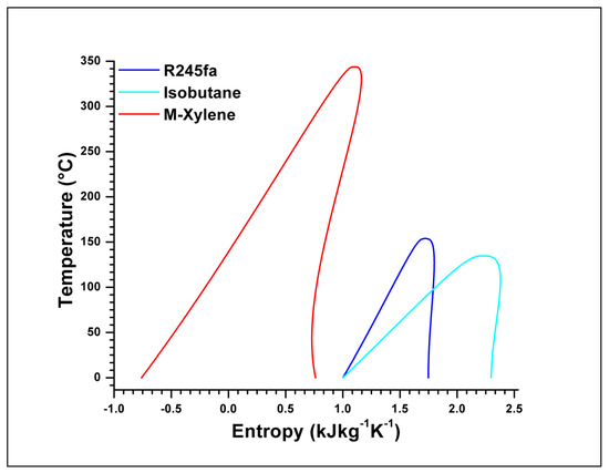
Figure 2.
Temperature - entropy diagram of the working fluids considered in present study.
Table 2.
Properties of the working fluids [15,33,48].
4. Results and Discussion
To conduct the analysis, an in-house algorithm was developed with the likes of some of the authors’ previous work [15] as presented below in Figure 3, and its validation in accordance with the works of the Tchanche et al. [49] is presented in Table 3. The code was developed in the MATLAB programming environment, and the state point properties were evaluated using REFPROP, whereas, in the works of Tchanche et al. [49], Engineering Equation Solver was used. The developed code is generic in nature and can be adjusted accordingly.
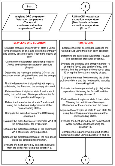
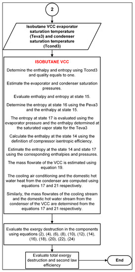
Figure 3.
Algorithm for the evaluation of the properties for the complete trigeneration system.
Table 3.
Validation of the present simulation with Ref. [49], considering the conditions of Ref. [49] for ORC.
The influence of different parameters is discussed in this section. Firstly, the results based on the baseline values are presented, and then afterward, the sensitivity analysis is presented. The parameters analyzed are the saturation temperatures of the evaporator and condensers of the medium temperature ORC, the saturation temperatures of the evaporator and condensers of the low temperature heat powered ORC, and the saturation temperatures of the condenser and the evaporator of the VCC. The baseline conditions and the range of parameters analyzed in this study are presented in Table 4 below.
Table 4.
The baseline conditions and the range of parameters considered for the sensitivity analysis.
4.1. Baseline Result
The baseline results are presented in Table 5. The value of cooling at the baseline conditions is approximately 17.5 kW, while the total heating utility that could be gathered from the system was found to be around 937 kW. Out of which, the maximum was seen to be displayed by the heat collected from the medium temperature heat source powered ORC. The main reason for this can be attributed to a high degree of superheating shown by M-xylene. The high degree of superheating causes the temperature at the turbine exit to be very high, around 194 °C. It is the same reason that the condenser of the M-xylene ORC also portrays a high level of exergy destruction. Overall, at the baseline conditions, the condensers of the M-xylene and the Isobutane VCC show relatively larger values of exergy destruction. Thus, pointing out the fact that their saturation temperatures could be lowered. Moreover, the boiler section of the M-xylene ORC also displays considerable exergy destruction when compared with the exergy destruction values of other components. Additionally, the outlet temperature at state 3 was found to be approximately 122 °C. Although this temperature could be used for providing additional utilities, care must be taken to avoid the dew point temperature of the water vapors. These water vapors upon fluctuations in the system could form condensate and result in the formation of sulphuric acid, thereby being detrimental to the system. Furthermore, the impact of the saturation temperatures, therefore, shall be sought in the proceeding section.
Table 5.
Results at the baseline conditions.
4.2. Parametric Analysis
As mentioned in the preceding section, the impact of various design parameters selected to be the saturation temperatures of the condensers and evaporators of the M-xylene ORC, R245fa ORC, and the Isobutane VCC are presented in this section. These parameters were selected and presented in this study due to their more considerable contribution to the exergy destruction and the cooling and heating utilities’ values compared with the other parameters. Other parameters, such as the degree of superheats and the pinch point temperature differences, were excluded. These parameters, together, have been observed to actually change the saturation temperatures, which in turn alters the values of the performance indices. Therefore, as the first step, the focus is kept on the saturation temperatures of the evaporators and the condensers. It is worth highlighting here that while conducting an analysis of a particular design parameter, all the other parameters are held constant.
The trends of the generated cooling, heating, and the second law efficiency as the saturation evaporation temperature of the M-xylene ORC was raised, are presented in Figure 4. The second law efficiency and the cooling and heating provided by the system display opposite trends. As the evaporation temperature of the prime mover increases, its mass flow rate decreases, keeping in view that the power outlet of the ORC is kept constant at 250 kW. The maximum destruction in comparative terms was found to be displayed by the M-xylene ORC components, and it is shown in Figure 5.
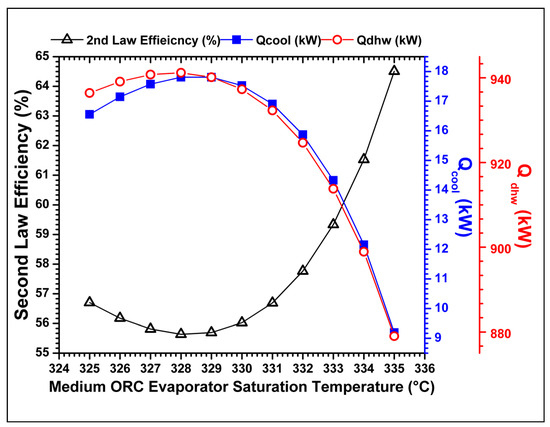
Figure 4.
The variation of the cooling, heating, and second law efficiency against the saturation evaporation temperature of the medium temperature heat source powered ORC.
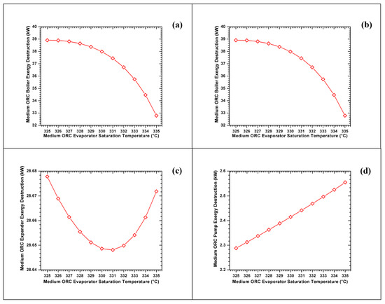
Figure 5.
The exergy destruction rates of different components of (a) boiler, (b) condenser, (c) expander, (d) pump of the M-Xylene ORC against its boiler saturation temperature.
The most major reduction in the exergy destruction was observed to be in the boiler due to the relatively rapid lessening of the log mean temperature difference. The reduction in the exergy destruction rate in the prime mover’s boiler was observed to be approximately 18.66%. To understand the behavior of the exergy destruction rate of the expander, consider Figure 6. The lowest exergy destruction rate, though not so appreciable, was found at the point where the gradient dT/dS was infinite at the expander inlet temperature of 331 °C represented by black point in Figure 6. The lower and upper bounds of the evaporator saturation temperature for this investigation are represented by the blue and yellow lines in Figure 6. Above this temperature, the exergy destruction rate increased. Though the working fluid passes slightly through the two-phase region in case the boiler saturation temperatures above 331 °C, but at this point, according to the review article by Chen et al. [50], very fine mist is temporarily formed and is harmless for the expander. Owing to this condition, the second law efficiency was observed to increase by approximately 14.8% of the base values.
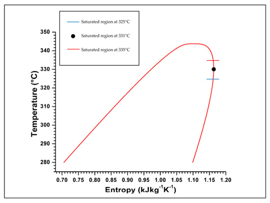
Figure 6.
Temperature–entropy diagram of the M - Xylene at the selected region.
To variation in the cooling requirements shown in Figure 4 happens because as the M-Xylene ORC evaporator temperature increases, keeping the condenser saturation temperature and the work output of 250 kW constant, the mass flowrate of the medium ORC changes in the fashion as shown in Figure 7a. Meanwhile the heat vaporization of the medium ORC saturation varies in the way as represented in Figure 7b. When the energy balance is applied on the heat of vaporization (latent) part of the evaporator, keeping the Therminol VP-1 input temperature at 370 °C and pinch point temperature difference at 10 °C, the mass flow rate of the flue gases changed in the way as shown in Figure 7c. In doing so, from the energy balance, the flue gases outlet temperature from the medium ORC heat exchangers, which is basically the Lower ORC evaporator inlet temperature varies with respect to the fashion as shown in Figure 7d. From the energy balance on the vaporization (latent) part of the R245fa ORC evaporator, keeping its saturation temperature at 130 °C, the mass flowrate changes in the following fashion, as displayed in Figure 7e. Meanwhile, the work generated by the expander of the R245fa ORC follows the trend portrayed in Figure 7f. As the saturation temperatures of the VCC are kept fixed, the variation in the expander work from the R245fa ORC, which is the VCC’s compressor work decreases, thereby reducing the cooling capacity.
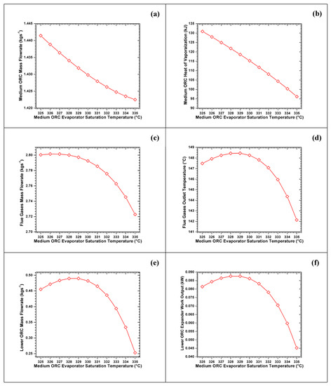
Figure 7.
The variation of (a) medium ORC mass flowrate, (b) medium ORC heat of vaporization, (c) flue gases mass flowrate, (d) flue gases outlet temperature, (e) low ORC mass flowrate, (f) low ORC expander work output against the medium ORC evaporator saturation temperature.
The impact of the saturation condensation temperature of M-xylene ORC on the values of cooling, heating, and the second law efficiencies R245fa ORC are displayed in Figure 8. The second law efficiency decreases sharply due to an increase in the temperature difference between the cooling source and the working fluid. The increase in the heating is due to the increased mass flow rate of the M-xylene ORC. Then, the difference between the enthalpy at the expander inlet and the outlet decreases, and it has a constraint to generate a fixed quantity of electricity. Furthermore, this increment in the M-xylene ORC also renders the greater requirement of the heat from the heat transfer fluid, thus causing it to increase its mass flow rate and in turn, increasing the mass flow rate (the consumption of biomass) to increase. This increment in the biomass consumption makes more heat available to the R245fa ORC. Thereby increasing its work output and hence the work input of the compressor of the VCC, which considered to be operating between the same pressure levels, increases its mass flow rate, causing a rise in the delivered cooling.
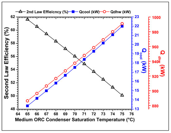
Figure 8.
The variation of the cooling, heating, and second law efficiency against the saturation condensation temperature of the medium temperature heat source powered ORC.
The trends regarding the delivered cooling, heating, and the second law efficiencies with the variation of the R245fa ORC saturation evaporation temperature are displayed in Figure 9. As the R245fa ORC evaporation saturation temperature increases, the temperature difference between the evaporation temperature difference and the heat source decreases, hence decreasing the irreversibility and raising the values of the overall second law efficiencies. On the other hand, due to the increment in the evaporation saturation temperature, the outlet temperature of the flue gases out of the R245fa ORC also increases, causing the temperature difference between the boiler inlet and outlet temperature to decrease. This, in turn, causes less amount of heat to be delivered to the ORC, causing its mass flow rate to decrease and produce less amount of work and in turn making the VCC to deliver less amount of cooling. Moreover, this lesser amount of mass flowrate also causes less heat to be delivered to the district heating stream at the condenser end of the R245fa ORC, henceforth causing the overall heat delivered to the district to decrease.
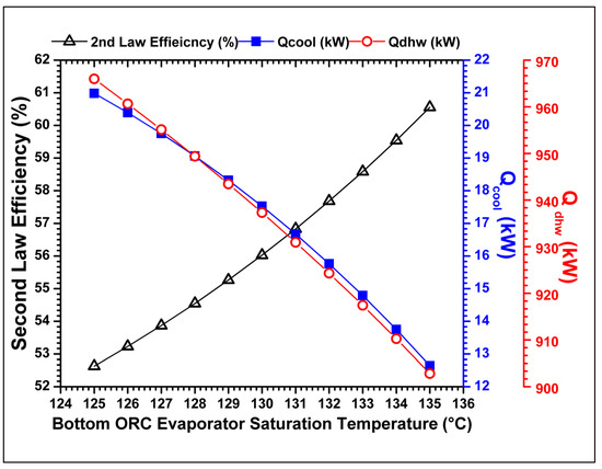
Figure 9.
The variation of the cooling, heating, and second law efficiency against the saturation evaporation temperature of the low temperature heat source powered ORC.
The trends of the variation of the cooling, heating, and the second law efficiencies against the saturation condenser temperatures of the R245fa ORC are shown in Figure 10. As the R245fa ORC condenser saturation temperature increases, although the exergy destruction in the condenser increases, but the exergy destruction in other components decreases. The reason is that as the condenser temperature increases, the gap between the saturated vapor enthalpy and the saturated liquid enthalpy decreases. This narrowing down causes the mean temperature difference in the boiler section between the working fluid and the heat source to decrease, causing a positive trend at this end. Additionally, the irreversibilites in the pump and the expander section decrease. Although the overall second law efficiency increases, its increase is very marginal, as its value only increases from 54.8% to 57.2% as we raise the condensation saturation temperature from 65 to 75 °C. Furthermore, such an increase causes a lesser amount of heat transferred to the associated district heating stream, owing to the decreased value of the latent heat of vaporization. Furthermore, the increment of the condensation saturation temperature reduces the work done by the R245fa ORC, thereby rendering less amount of cooling utility production at the VCC end.
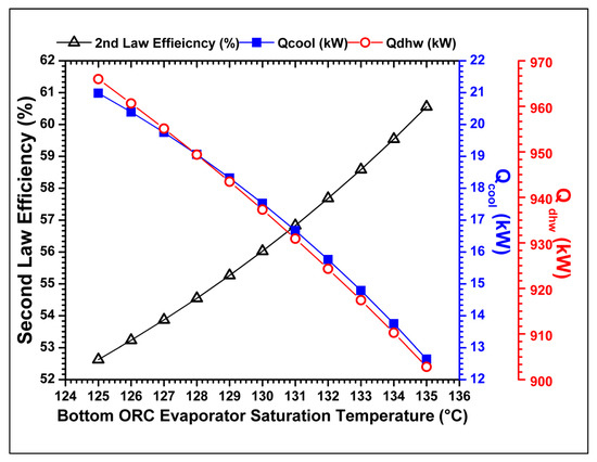
Figure 10.
The variation of the cooling, heating, and second law efficiency against the saturation condensation temperature of the low temperature heat source powered ORC.
The effects of varying the VCC condensation saturation temperature on the cooling, heating, and the second law efficiency are shown in Figure 11. As the condenser saturation temperature increases, the exergy destruction rates of the compressor, evaporator, and the throttling valve increases, but as opposed to expectations, the exergy destruction of the condenser decreases. On closer inspection of the Equation (22), it was revealed that due to the narrowing TS diagram dome, the difference between the specific entropies reduces, thereby decreasing the exergy destruction rate in the condenser of the VCC. Consequentially the increment in the condenser saturation temperature decreases the amount of heat it could disperse to the district heating stream. Moreover, due to the narrowing of the dome, the working fluid flashes to higher quality at the evaporator inlet, thus having a lesser amount of charge to gather more heat from the district cooling stream.
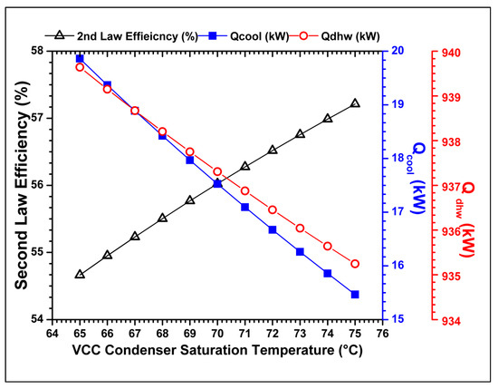
Figure 11.
The variation of the cooling, heating, and second law efficiency against the saturation condensation temperature of the VCC.
The influence of the VCC evaporation saturation temperature on the cooling, heating, and the second law efficiency is shown in Figure 12. As the evaporation pressure is increased, the entropy difference was found to increase, thereby increasing the values slightly. The slight increase in the heating value is due to the slight increase in the mass flow rate of the VCC due to the shortening of the pressure difference. Nevertheless, the heating value increment is nominal as it only increases from 934.5 kW at −5 °C to 937 kW at 2 °C. On the other hand, the cooling value increases with an increase in the saturation condensation temperature, again due to the increase mass flow rate due to the lesser pressure difference between the condenser and the evaporator.
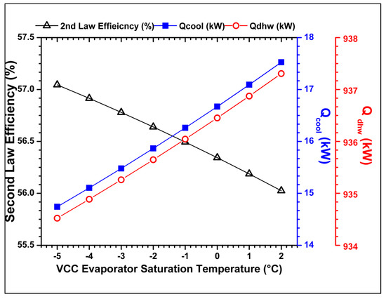
Figure 12.
The variation of the cooling, heating, and second law efficiency against the saturation evaporation temperature of the VCC.
5. Conclusions
This study presents a simple trigeneration system based on the medium temperature heat driven ORC primed CCHP system. The system incorporates an ORC-VCC for cooling production. The proposed system is considered to use biogas and is aimed at small scale community level. To run such a system in order to obtain the daily life essentials of electricity, hot water, and cooling, municipal waste can be considered as an option. Furthermore, the ORC part of the ORC-VCC can be used in times of need for additional electric production. As a preliminary thermal study, the system design parameters of the saturation temperatures were considered, and the following inferences were deduced.
- The impact of the design parameters in the prime mover has a more significant effect on the whole system. Additionally, the degree of affecting the overall system performance starts to get relatively less significant as we travel downstream of the main heating branch.
- When the evaporation saturation temperature of the prime mover is raised, the second law efficiency increases, from 56.7% to 64.5%, but in doing so, the quantity of heating and cooling decreases. That is in the case of cooling, the value decreases from 16.5 to 9 kW (46.88%), and for the heating, it decreases from 936.42 to 879 kW (6.13% decrease). This scheme could be useful in the operation step when the cooling requirement becomes more desirable.
- Similarly, when the evaporation saturation temperature of the ORC part of the ORC-VCC is increased, the second law efficiency increases from 52.6% to 60.6%, but the cooling production gets lowered from approximately 21 kW to approximately 13 kW (38% decrement). Additionally, in this case, the production of heating reduces from approximately 966 to 903 kW (6.5% decrement).
- Similar behavior was shown when the condensation saturation temperature of the ORC part of the ORC-VCC was increased. For this scenario, the second law efficiency increased from 55% to 57%. Whereas the cooling production reduced from 19 to 16 kW (15.8% decrement), and the heating production reduced from 943 to 932 kW (1.17% decrement).
- The second law efficiency increases from 54.7% to 57.2% with an increase in the VCC condenser saturation temperature, and it decreases from 57% to 56% with the increase of the VCC evaporation saturation temperature. Meanwhile, the cooling production decreased from 20 to 15.5 kW (22.5% decrement), when the VCC condenser saturation temperature was increased. In addition, the increment of the cooling utility in the case, when the VCC evaporation saturation temperature was increased, was observed to be from 15 to 17.5 kW (16.6% increment). Regarding hot water production, it decreased from 940 to 935 kW (0.5% decrement) for the increase in the VCC condenser saturation temperature. For the VCC saturation temperature, the heating production was from 934.5 to 937 kW (0.27% increment).
Author Contributions
Conceptualization, M.T.N.; methodology, M.T.N.; software, M.T.N.; validation, M.T.N.; formal analysis, M.T.N.; investigation, M.T.N.; resources, M.T.N.; data curation, M.T.N.; writing—original draft preparation, M.T.N. and M.C.E.; writing—review and editing, M.T.N., M.C.E., J.A.E. and K.C.K.; visualization, M.C.E. and Y.P.; supervision, K.C.K.; project administration, K.C.K.; funding acquisition, K.C.K. All authors have read and agreed to the published version of the manuscript.
Funding
The research and the APC was funded by the National Research Foundation of Korea, grant number 2020R1A5A8018822.
Data Availability Statement
Data is contained within the article.
Acknowledgments
This study was supported by the National Research Foundation of Korea (NRF) grant, which is. This work was supported by Brain Pool Program through the National Research Foundation of Korea (NRF), funded by the Ministry of Science and ICT (NRF-2020H1D3A2A01104062). This work was also supported by the National Research Foundation of Korea (NRF) grant, which is funded by the Korean government (MSIT) (No. 2020R1A5A8018822).
Conflicts of Interest
The authors declare no conflict of interest.
Definitions/Abbreviations
| cP | Specific heat, kJ/kg·K |
| CCHP | Combined cooling heating and power |
| Exergy of destruction, kW | |
| H | Specific enthalpy, kJ/kg |
| HTF | Heat transfer fluid |
| Mass flowrate, kg/s | |
| ORC | Organic Rankine cycle |
| Heat transfer rate, kW | |
| s | Entropy, kJ/kgK |
| T | Temperature, °C |
| VCC | Vapor compression cycle |
| Work transfer, kW | |
| Subscripts | |
| 1, 2, 3, … | State numbers |
| II | Second |
| fg | Flue gases |
| LowORC, boil | Low ORC boiler |
| LowORC, cond | Low ORC condenser |
| LowORC, exp | Low ORC expander |
| LowORC, pump | Low ORC pump |
| LowORC | Low ORC |
| MedORC | Medium ORC |
| MedORC, boil | Medium ORC boiler |
| MedORC, cond | Medium ORC condenser |
| MedORC, exp | Medium ORC expander |
| MedORC, pump | Medium ORC pump |
| tot | Total |
| VCC, cond | VCC condenser |
| VCC, exp | VCC expander |
| VCC, pump | VCC pump |
| VCC, throt | VCC throttling value |
| Greek Symbols | |
| Second law efficiency |
Appendix A
The steady state energetic and exergetic models of the various components of the CCHP system are provided in this Appendix A.
The heat delivered by the flue gases to heat transfer fluid and to the evaporator of the medium ORC is given as:
The exergy destruction in the evaporator of the ORC is presented as:
Here, , is the dead state temperature.
The work done by the expander of the medium ORC is given as:
The exergy destruction in the expander of this ORC is given as:
The heat rejected by the condenser of the ORC, which is utilized by the district heating stream is calculated from the Equation (5):
The exergy destruction in the medium temperature ORC is calculated from the following equation:
The ORC pump work input is given as:
The exergy destruction in the pump of the medium temperature ORC is calculated from the following equation:
The heat balance equation on the boiler of the low temperature ORC is given as:
The exergy destruction in the boiler of the low temperature ORC is calculated from the following equation:
The work produced by the expander of the ORC is given as:
The exergy destruction in the expander of the low temperature ORC is given as:
The heat dissipated by the condenser of the ORC, and utilized by the district heating stream is calculated from the following equation:
The exergy destruction in the ORC condenser is calculated from the following equation:
The ORC pump work input is mathematically represented as:
The exergy destruction of the pump is given as:
The VCC gains heat via its evaporator while cooling the district cooling stream, and its equation is given as:
The exergy destruction in the VCC condenser is given as:
The VCC compressor work input is determined as:
The exergy destruction in the compressor of the VCC is given as:
The VCC condenser heat rejection and the simultaneous heat gain by the district heating stream is determined from Equation (21):
The rate of exergy destruction in the VCC condenser is given as:
The throttling valve expansion for this case is given as:
The exergy destruction in the throttling valve is computed using the following equation:
The total exergy destruction is mathematically given as:
The second law efficiency of the overall system is given as:
References
- IEA. World Energy Outlook 2019—Analysis; IEA: Paris, France, 2019; Available online: https://www.iea.org/reports/world-energy-outlook-2019 (accessed on 20 July 2020).
- Bianco, G.; Bracco, S.; Delfino, F.; Gambelli, L.; Robba, M.; Rossi, M. A Building Energy Management System Based on an Equivalent Electric Circuit Model. Energies 2020, 13, 1689. [Google Scholar] [CrossRef]
- Inglesi-Lotz, R. The impact of renewable energy consumption to economic growth: A panel data application. Energy Econ. 2016, 53, 58–63. [Google Scholar] [CrossRef]
- Moriarty, P.; Honnery, D. What is the global potential for renewable energy? Renew. Sustain. Energy Rev. 2012, 16, 244–252. [Google Scholar] [CrossRef]
- Nili-Ahmadabadi, M.; Nematollahi, O.; Fatehi, M.; Cho, D.S.; Kim, K.C. Evaluation of aerodynamic performance enhancement of Risø_B1 airfoil with an optimized cavity by PIV measurement. J. Vis. 2020, 23, 591–603. [Google Scholar] [CrossRef]
- Strzalka, R.; Schneider, D.; Eicker, U. Current status of bioenergy technologies in Germany. Renew. Sustain. Energy Rev. 2017, 72, 801–820. [Google Scholar] [CrossRef]
- Hollands, E.O.; He, C.; Gan, L. A particle image velocimetry study of dual-rotor counter-rotating wind turbine near wake. J. Vis. 2020, 23, 425–435. [Google Scholar] [CrossRef]
- Al Moussawi, H.; Fardoun, F.; Louahlia-Gualous, H. Review of tri-generation technologies: Design evaluation, optimization, decision-making, and selection approach. Energy Convers. Manag. 2016, 120, 157–196. [Google Scholar] [CrossRef]
- Trigeneration | Combined Cooling Heat and Power|CCHP. Clarke Energy. Available online: https://www.clarke-energy.com/trigeneration/ (accessed on 26 July 2020).
- Al-Sulaiman, F.A.; Hamdullahpur, F.; Dincer, I. Trigeneration: A comprehensive review based on prime movers. Int. J. Energy Res. 2011, 35, 233–258. [Google Scholar] [CrossRef]
- Al Moussawi, H.; Fardoun, F.; Louahlia, H. Selection based on differences between cogeneration and trigeneration in various prime mover technologies. Renew. Sustain. Energy Rev. 2017, 74, 491–511. [Google Scholar] [CrossRef]
- Figaj, R.; Sornek, K.; Podlasek, S.; Żołądek, M. Operation and Sensitivity Analysis of a Micro-Scale Hybrid Trigeneration System Integrating a Water Steam Cycle and Wind Turbine under Different Reference Scenarios. Energies 2020, 13, 5697. [Google Scholar] [CrossRef]
- Calise, F.; Cappiello, F.L.; D’Accadia, M.D.; Libertini, L.; Vicidomini, M. Dynamic Simulation and Thermoeconomic Analysis of a Trigeneration System in a Hospital Application. Energies 2020, 13, 3558. [Google Scholar] [CrossRef]
- Murugan, S.; Horák, B. Tri and polygeneration systems—A review. Renew. Sustain. Energy Rev. 2016, 60, 1032–1051. [Google Scholar] [CrossRef]
- Nasir, M.T.; Kim, K.C. Working fluids selection and parametric optimization of an Organic Rankine Cycle coupled Vapor Compression Cycle (ORC-VCC) for air conditioning using low grade heat. Energy Build. 2016, 129, 378–395. [Google Scholar] [CrossRef]
- Bao, J.; Zhao, L. A review of working fluid and expander selections for organic Rankine cycle. Renew. Sustain. Energy Rev. 2013, 24, 325–342. [Google Scholar] [CrossRef]
- Jradi, M.; Riffat, S.B. Experimental investigation of a biomass-fuelled micro-scale tri-generation system with organic Rankine cycle and liquid desiccant cooling unit. Energy 2014, 71, 80–93. [Google Scholar] [CrossRef]
- Karellas, S.; Braimakis, K. Energy-exergy analysis and economic investigation of a cogeneration and trigeneration ORC-VCC hybrid system utilizing biomass fuel and solar power. Energy Convers. Manag. 2016, 107, 103–113. [Google Scholar] [CrossRef]
- Navarro-Esbrí, J.; Molés, F.; Peris, B.; Mota-Babiloni, A.; Martí, J.P.; Collado, R.; González, M. Combined cold, heat and power system, based on an organic Rankine cycle, using biomass as renewable heat source for energy saving and emissions reduction in a supermarket. Energy Procedia 2017, 129, 652–659. [Google Scholar] [CrossRef]
- Wang, Z.; Li, H.; Zhang, X.; Wang, L.; Du, S.; Fang, C. Performance analysis on a novel micro-scale combined cooling, heating and power (CCHP) system for domestic utilization driven by biomass energy. Renew. Energy 2020, 156, 1215–1232. [Google Scholar] [CrossRef]
- Bellos, E.; Vellios, L.; Theodosiou, I.-C.; Tzivanidis, C. Investigation of a solar-biomass polygeneration system. Energy Convers. Manag. 2018, 173, 283–295. [Google Scholar] [CrossRef]
- Huang, Y.; Wang, Y.; Rezvani, S.; McIlveen-Wright, D.; Anderson, M.; Mondol, J.; Zacharopolous, A.; Hewitt, N. A techno-economic assessment of biomass fuelled trigeneration system integrated with Rankine Cycle. Appl. Therm. Eng. 2013, 53, 325–331. [Google Scholar] [CrossRef]
- Amirante, R.; Clodoveo, M.L.; Distaso, E.; Ruggiero, F.; Tamburrano, P. A tri-generation plant fuelled with olive tree pruning residues in Apulia: An energetic and economic analysis. Renew. Energy 2016, 89, 411–421. [Google Scholar] [CrossRef]
- Ahmadi, P.; Dincer, I.; Rosen, M.A. Thermoeconomic multi-objective optimization of a novel biomass-based integrated energy system. Energy 2014, 68, 958–970. [Google Scholar] [CrossRef]
- Al-Sulaiman, F.A.; Hamdullahpur, F.; Dincer, I. Greenhouse gas emission and exergy assessments of an integrated organic Rankine cycle with a biomass combustor for combined cooling, heating, and power production. Appl. Therm. Eng. 2011, 31, 439–446. [Google Scholar] [CrossRef]
- Mouaky, A.; Rachek, A. Energetic, exergetic, and exergoeconomic assessment of a hybrid solar/biomass polygeneration system: A case study of a rural community in a semi-arid climate. Renew. Energy 2020, 158, 280–296. [Google Scholar] [CrossRef]
- Boyaghchi, F.A.; Chavoshi, M. Multi-criterea optimization of a micro solar-geothermal CCHP system applying water/CuO nanofluid based on exergy, exergoeconomic and exergoenvironmental concepts. Appl. Therm. Eng. 2017, 112, 660–675. [Google Scholar] [CrossRef]
- Boyaghchi, F.A.; Chavoshi, M.; Sabeti, V. Optimization of a novel combined cooling, heating and power cycle driven by geothermal and solar energies using water/CuO (copper oxide) nanofluid. Energy 2015, 91, 685–699. [Google Scholar] [CrossRef]
- Bellos, E.; Tzivanidis, C. Multi-objective optimization of a solar driven trigeneration system. Energy 2018, 149, 47–62. [Google Scholar] [CrossRef]
- Bellos, E.; Tzivanidis, C. Parametric Investigation of a Trigeneration System with an Organic Rankine Cycle and Absorption Heat Pump Driven by Parabolic Trough Collectors for the Building Sector. Energies 2020, 13, 1800. [Google Scholar] [CrossRef]
- Tzivanidis, C.; Bellos, E. A Comparative Study of Solar-Driven Trigeneration Systems for the Building Sector. Energies 2020, 13, 2074. [Google Scholar] [CrossRef]
- Aneke, M.; Agnew, B.; Underwood, C.; Menkiti, M.C. Thermodynamics analysis of alternative refrigeration cycles driven from waste heat in a food processing application. Int. J. Refrig. 2012, 35, 1349–1358. [Google Scholar] [CrossRef]
- Aziz, F.; Mudasar, R.; Kim, M.-H. Exergetic and heat load optimization of high temperature organic Rankine cycle. Energy Convers. Manag. 2018, 171, 48–58. [Google Scholar] [CrossRef]
- Johnson, I.; Choate, W.T.; Davidson, A. Waste Heat Recovery. Technology and Opportunities in U.S. Industry; Department of Energy, Office of Energy Efficiency and Renewable Energy: Washington, DC, USA, 2008. [CrossRef]
- Wang, E.; Zhang, H.; Fan, B.; Ouyang, M.; Zhao, Y.; Mu, Q. Study of working fluid selection of organic Rankine cycle (ORC) for engine waste heat recovery. Energy 2011, 36, 3406–3418. [Google Scholar] [CrossRef]
- Nasir, M.T.; Ali, M.A.; Khan, T.S.; Al-Hajri, E.; Kadri, M.B.; Kim, K.C. Performance assessment and multi objective optimization of an Organic Rankine Cycle driven cooling air conditioning system. Energy Build. 2019, 191, 13–30. [Google Scholar] [CrossRef]
- Xianbiao, X.; Wang, L.; Li, H. Performance analysis and working fluid selection for geothermal energy-powered organic Rankine-vapor compression air conditioning. Geotherm. Energy 2013, 1, 2. [Google Scholar] [CrossRef]
- Zheng, N.; Wei, J.; Zhao, L. Analysis of a solar Rankine cycle powered refrigerator with zeotropic mixtures. Sol. Energy 2018, 162, 57–66. [Google Scholar] [CrossRef]
- Moran, M.J.; Shapiro, H.N. Fundamentals of Engineering Thermodynamics, 5th ed.; John Wiley & Sons Ltd.: Hoboken, NJ, USA, 2006. [Google Scholar]
- Ҫengel, Y.; Boles, M. Thermodynamics—An Engineering Approach, 5th ed.; Mc Graw Hill Education: Boston, MA, USA, 2006. [Google Scholar]
- Razi, F.; Dincer, I. A new solar combined cycle integrated with heat pump system. Appl. Therm. Eng. 2020, 173, 114784. [Google Scholar] [CrossRef]
- Toffolo, A.; Lazzaretto, A.; Manente, G.; Paci, M. A multi-criterea approach for the optimal selection of working fluid and design parameters in Organic Rankine Cycle systems. Appl. Energy 2014, 121, 219–232. [Google Scholar] [CrossRef]
- Meng, N.; Li, T.; Wang, J.; Jia, Y.; Liu, Q.; Qin, H. Synergistic cascade-evaporation mechanism of a novel building distributed energy supply system with cogeneration and temperature and humidity independent control characteristics. Energy Convers. Manag. 2020, 209, 112620. [Google Scholar] [CrossRef]
- Yilmaz, A. Transcritical organic Rankine vapor compression refrigeration system for intercity bus air-conditioning using exhaust heat. Energy 2015, 82, 1047–1056. [Google Scholar] [CrossRef]
- Coskun, C.; Oktay, Z.; Ilten, N. A new approach for simplifying the calculation of flue gas specific heat and exergy value depending on fuel consumption. Energy 2009, 34, 1898–1902. [Google Scholar] [CrossRef]
- Therminol® VP-1. Available online: http://www.therminol.com/products/432Therminol-VP1 (accessed on 28 August 2020).
- Wang, J.; Lu, Z.; Li, M.; Lior, N.; Li, W. Energy, exergy, and exergoeconomic and environmental (4E) analysis of a distributed generation solar-assisted CCHP (combined cooling, heating and power) gas turbine system. Energy 2019, 175, 1246–1258. [Google Scholar] [CrossRef]
- Lemmon, E.W.; Huber, M.L.; McLinden, M.O. NIST Standard Reference Database 23: Reference Fluid Thermodynamic and Transport Properties-REFPROP, Version 9.1; NIST Publications: Gaithersburg, MD, USA, 2013. [Google Scholar]
- Tchanche, B.F.; Papakadis, G.; Lambrinos, G.; Frangoudakis, A. Fluid selection for a low temperature organic Rankine cycle. Appl. Therm. Eng. 2009, 29, 2468–2476. [Google Scholar] [CrossRef]
- Chen, H.; Goswami, D.Y.; Stefanakos, E.K. A review of thermodynamic cycles and working fluids for the conversion of low-grade heat. Renew. Sustain. Energy Rev. 2010, 14, 3059–3067. [Google Scholar] [CrossRef]
Publisher’s Note: MDPI stays neutral with regard to jurisdictional claims in published maps and institutional affiliations. |
© 2021 by the authors. Licensee MDPI, Basel, Switzerland. This article is an open access article distributed under the terms and conditions of the Creative Commons Attribution (CC BY) license (http://creativecommons.org/licenses/by/4.0/).