Article

Thermodynamic Study of a Combined Power and Refrigeration System for Low-Grade Heat Energy Source

by
Saboora Khatoon
,
Nasser Mohammed A. Almefreji
and
Man-Hoe Kim
*
School of Mechanical Engineering & IEDT, Kyungpook National University, Daegu 41566, Korea
*
Author to whom correspondence should be addressed.
Energies 2021, 14(2), 410; https://doi.org/10.3390/en14020410
Submission received: 2 December 2020 / Revised: 31 December 2020 / Accepted: 11 January 2021 / Published: 13 January 2021

Abstract

:
This study focuses on the thermal performance analysis of an organic Rankine cycle powered vapor compression refrigeration cycle for a set of working fluids for each cycle, also known as a dual fluid system. Both cycles are coupled using a common shaft to maintain a constant transmission ratio of one. Eight working fluids have been studied for the vapor compression refrigeration cycle, and a total of sixty-four combinations of working fluids have been analyzed for the dual fluid combined cycle system. The analysis has been performed to achieve a temperature of −16 °C for a set of condenser temperatures 34 °C, 36 °C, 38 °C, and 40 °C. For the desired temperature in the refrigeration cycle, the required work input, mass flow rate, and heat input for the organic Rankine cycle were determined systematically. Based on the manifestation of performance criteria, three working fluids (R123, R134a, and R245fa) were chosen for the refrigeration cycle and two (Propane and R245fa) were picked for the organic Rankine cycle. Further, a combination of R123 in the refrigeration cycle with propane in the Rankine cycle was scrutinized for their highest efficiency value of 16.48% with the corresponding highest coefficient of performance value of 2.85 at 40 °C.

1. Introduction

To improve the energy efficiency in the industrial world, heat recovery technologies employing standalone and combined cycle configurations have been advanced and improved continuously. All the energy-related challenges covering the resources, demand, and supply, as well as their applications, have always been a high concern issue globally. Governments around the globe, in particular, from developed nations such as the US and UK, have constantly allocated substantial budgets at national and international levels to bring contemporary evaluations on relevant issues. The most recent examples include the independent assessment delivered by the UK Committee on Climate Change [1] and the International Energy Outlook 2018 [2] by the US Energy Information Administration. To specify the seriousness of energy-related issues, the projected world energy consumption will reach up to 736 quadrillion British thermal units (Btu) by 2040. This, in general, includes an 18% increase in the industrial sector along with a 50% increase in total world energy consumption. The UK government has set a national target to accomplish (<20%) improvement in industrial energy efficiency by 2030 [1]. Action plans are being established by all governments, such as enabling innovation and improvement opportunities across the globe.
Implementing thermally efficient practices and taking advantage of industrial waste heat are some examples of possible techniques to improve industrial energy efficiency. With the deployment of advanced technologies, low-grade heat has the potential in producing (a) electrical power; (b) electricity, heat, and cooling simultaneously; (c) water desalination as well as (d) hydrogen production. The integration of bottoming cycles with high-temperature heat to power conversion cycles is an attractive option for future power generation systems [3]. Organic Rankine cycles (ORC) are a potential way to harness industrial waste to abate environmental issues. The simple construction, low operational cost, great flexibility, and relatively higher waste-heat recovery efficiency of ORC make them an obvious choice for power production from low-grade heat energy sources [4]. A wide range of heat sources can be applied to ORC systems, such as waste heat from industrial processes, from the condenser of a steam power plant, from the heat sink of supercritical carbon dioxide Brayton cycle, solar radiation, as well as geothermal energy. Various studies are available in the literature that has used the ORC unit to recover low to medium temperature waste heat. Koç [5] proposed a cogeneration system that was able to recover 30% waste heat using ethanol working fluid for the ORC unit.
While consuming a low grade-heat source, the efficiency and capital cost of each proposed combined system further depends on employed working fluid. The temperature profile of organic fluid in the receiver heat exchanger has a significant effect on system performance [6]. Because of irreversibility losses in the practical application of combined power and refrigeration cycles, it is not possible to all the available waste heat energy into useful work. The thermodynamic performance of the power cycles can also be improved by using a binary mixture of fluids [7] or zeotropic mixtures [8]. A thorough investigation of ORC for increased efficiency of converting low-grade heat to useful work was conducted by Hung et al. [9] by categorizing working fluids into wet, dry, and isentropic fluids. Jeong and Kang [10] developed a novel refrigeration cycle driven from a refrigerant steam turbine. The developed model has a simple mechanical system, and thermodynamic analysis was performed using R123, R134a, and R245ca. The study revealed that with the proposed configuration R245ca was the most promising refrigerant.
To further improve the performance of ORC, some new combined systems have been proposed by researchers [11], such as; combining ORC with absorption refrigeration cycle [12], Rankine and ejector–absorption refrigeration cycle [13] ORC, and vapor compression refrigeration cycle (VCC) [14]. In absorption refrigeration configuration, absorption condensation is used instead of the conventional condensation process. But it involves additional challenges such as toxicity of working fluid-ammonia and corrosion. For ejector refrigeration, the irreversibility losses of the system increased while the heat addition process and highest exergy losses occur in the ejector. Khaliq et al. [15] presented an improved performance of the system by limiting turbine inlet and backpressure. Riaz et al. [16] performed a detailed parametric analysis of a low-grade waste-heat driven ejector refrigeration system. The computed results showed that for the optimum design of the ejector refrigeration system, the generator pressure increases linearly with heat source temperature. A simulation study for alternative refrigeration cycles by Aneke et al. [17] showed that the ORC driven VCC system provided a better coefficient of performance and second law efficiency. The ORC-Vapor compression refrigeration system is advantageous for its simple components and easier compatibility with ORC. Also, the direct coupling of the ORC-turbine and VCC-compressor contributes to reduced mechanical energy losses [10]. This combined power and refrigeration system is an efficient way to fulfill the thermo-mechanically activated refrigeration system.
The selection of working fluid is of critical importance for efficient power production from ORC. Thermodynamic properties of working fluid influence the thermal efficiency, Wang et al. [18] presented a theoretical model for their study based on an ideal ORC. Demierre et al. [19] presented an experimental investigation of a vapor compression heat pump cycle coupled to an ORC using a single-stage centrifugal compressor that was directly derived from the turbine, which produced a 40 kW heating capacity. In a recent study by Bao et al. [20], they compared single and dual fluid system configurations of ORC-VCC systems. Using geothermal water of 140 °C, they studied the flash tank vapor injection cycle which is coupled with ORC with different working fluids. Kim and Blanco [21] performed the evaluation of an ORC-VCC system for eight working fluids using efficiencies and size parameters. Aphornratana and Sriveerakal [22] investigated an ORC-VCC system sharing a single working fluid through a common condenser coupled using a single piston expander-compressor unit. Under the examined parameters of their study, R22 showed the best performance from the prospective of the coefficient of performance (COP). Liang et al. [23] proposed a waste-heat driven, from internal combustion engine exhaust, cooling configuration based on ORC-VCC coupled configuration. Ochoa et al. [24] made a thermoeconomic study for the waste-heat recovery from a gas engine using different working fluids. Li et al. [25] studied the single fluid ORC-VCC system suing several hydrocarbons for the boiler temperature range of 60–90 °C. A transcritical ORC-VCC system using waste heat of engine exhaust was investigated by Yilmaz [26]. Wet (R134a) and dry (R245fa) refrigerant were used for different engine loads with the conclusion that desired cooling was achievable even with 50% engine load. Possible working fluids for the ORC-VCC system are countless. For optimum energy efficiency of the system, the working fluid should have low global warming potential (GWP), along with good system performance. Therefore, the selection of working fluid for a given heat source temperature range in ORC requires extensive analysis.
With this background, the present exercise is taken with the specific objective of carrying out system analysis for overall system improvement. The refrigeration cycle is modeled to provide air at −16 °C temperature in accordance with the low-temperature requirement for food preservation applications to avoid microbial activity. In this work, a thermally activated ORC serving as a prime mover for VCC using various combinations of working fluids was analyzed. The desired cooling temperature and correspondingly needed compressor worked in VCC serve as the input parameters to compute the mass flow rate and heat needed in the vapor generator of ORC. Since the normal boiling point of most of the organic working fluids was lesser than that of water, the studied system can easily be integrated with low temperature heat sources such as waste heat from fishing boats and industrial processes, biomass combustion, geothermal, and solar. The system has been evaluated theoretically using a mathematical model developed in MATLAB. Combining power generation and refrigeration improves the system coefficient of performance with the proper selection of working fluids.

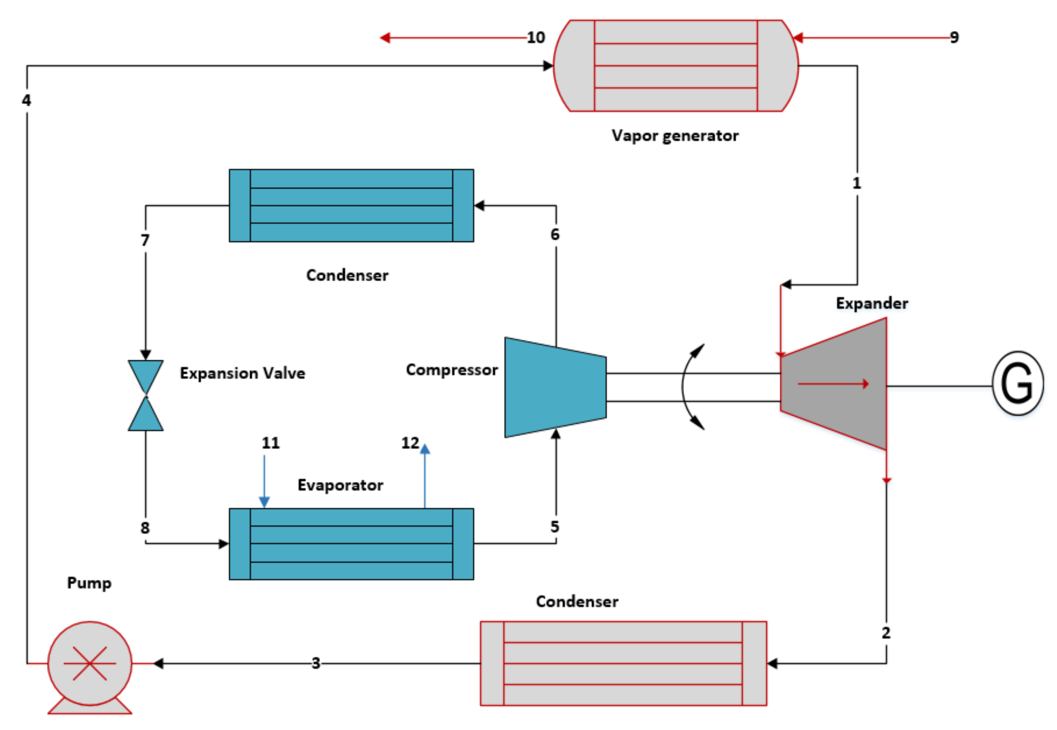
2. System Configuration Description

Figure 1 shows the schematic of the organic Rankine cycle coupled to a vapor compression refrigeration cycle. The working fluid in the ORC at state point 1 (in superheated form), after gaining heat from the vapor generator, expands in the expander to generate electric energy as well as to run the compressor of the refrigeration cycle. At state point 2, working fluid enters the condenser to reject the heat to the heat sink and changes its phase from vapor to liquid. After that, the working fluid enters the pump as liquid (state point 3) and is compressed from low pressure P3 to high pressure P4. This high pressure working fluid reaches the vapor generator at state point 4 and receives heat from the heat energy source, approaches the system at state point 9, and leaves the system at state point 10 after rejecting heat in the vapor generator of the ORC system. The coupled VCC system utilizes a different working fluid. From the expander of the ORC, the compressor of the refrigeration cycle gains power. Refrigeration fluid enters the compressor at state point 5, where it is compressed to meet the pressure P6 (state point 6) before entering the condenser and rejects the heat to the environment. At state point 7, the working fluid undergoes isenthalpic expansion in the expansion device. The air from the desired cooling area enters the evaporator at state point 11. Refrigeration fluid entering the evaporator in liquid form (at state point 8) absorbs the heat of this incoming air and changes its phase from liquid to vapor. The cooled air leaves the evaporator of the VCC cycle at state point 12.

3. Mathematical Modeling

The thermodynamic analysis of the system was performed according to the laws of conversation of mass and energy. Cycle simulations were performed using MATLAB and fluid properties of each working fluid were computed using REFPROP [27]. MATLAB and REFPROP were coupled using a function available on the REFPROP website. The REFPROP function can compute all the properties with two known independent state properties. For example, enthalpy h 1 at state point 1 is computed as a function of known temperature T 1 and pressure P 1 i.e., h 1 = f T 1 ,   P 1 . This way the thermodynamic property calculations in MATLAB environment become easier and quicker. The energy balance relations for each component of the studied system are presented in this section.
(1-2) ORC expander
The power generated from the ORC expander can be calculated as:
W e x p =   m O R C h 1 h 2 = m O R C h 1 h 2 s η e x p
(2-3) ORC condenser
The heat rejected in the ORC condenser can be calculated as:
Q c o n d   = m O R C h 2 h 3
(3-4) ORC pump
The power consumed by the pump can be calculated as:
W P   = m O R C h 4 h 3 = m O R C h 4 s h 3 / η P
(4-1) Vapor generator
The heat to be received in the ORC vapor generator can be calculated as
Q v a p =   m O R C h 4 h 1 = m s h 9 h 10
where, m s is the mass flow rate of heat transfer fluid from heat source.
(5-6) VCC compressor
The power consumed by the compressor can be calculated as:
W c o m   = m V C C h 6 h 5 = m V C C h 6 h 5 s η c o m
(6-7) VCC condenser
The heat rejected in the condenser-VCC can be calculated as:
Q c o n d   V C C =   m V C C h 6 h 7
(7-8) Expansion valve
The working fluid flowing through the expansion valve can be taken as an isenthalpic throttling process:
h 7 = h 8
(8-5) Evaporator
The heat transferred in the evaporator-VCC can be calculated as:
Q e v a p   V C C =   m V C C h 5 h 8
Coefficient of performance (COP)
C O P =   Q e v a p   V C C   W c o m
The thermal efficiency of the ORC is dependent on the net work output and heat supplied in the vapor generator, expressed as;
ɳ t h =   W e x p W P Q v a p

3.1. Environmental Conditions and Process Assumptions

The temperature-entropy diagram of the studied system is shown in Figure 2. Some constraints of the studied system and assumptions to avoid the complexity of the system are described below:
  • The system operation is at steady state conditions.
  • The heat and frictional losses are negligible.
  • The variations in kinetic and potential energy are not considerable.
  • The ambient air, to be cooled, is assumed to be completely dry.
  • The work produced by the ORC expander and work consumed by VCC is equal.
  • The throttling valve operation is isenthalpic.
  • The ORC expander, pump, and VCC compressor have an isentropic efficiency value of 80% [28].
  • A pinch point temperature of 2 °C is considered for all the heat exchangers.

3.2. Validation

The model developed in the MATLAB environment, using the energy relations mentioned earlier was tested for each of the cycles. The ORC model was validated by comparing the efficiency results of Saleh [14] and the present study. The computed values for ORC fluids R245fa and R1234ze at 100 °C heat supply temperature and 1267 kPa cycle maximum pressure while observing the operational constraints mentioned in the reference are plotted in Figure 3. At the same time, the VCC model was compared for cooling application with the results of Nasir and Kim [28] to ensure the accuracy of the developed model. The computed COP values for a set of condenser temperatures using R245fa are presented in Figure 3. It can be seen that the percentage difference in the computed parameters is negligible for both of the cycles signifying the accuracy of the developed models.

3.3. Selection of Working Fluids

The performance of the standalone or combined ORC configurations is strongly influenced by the selection of working fluids. ORC working fluids are categorized as dry, wet, and isentropic fluids. This categorization is based on the slope of the saturation vapor line on the TS-diagram for the respective working fluid. A positive, negative, and extremely broad slope represents dry, wet, and isentropic fluid, respectively. With the present cycle architect, following criteria [29] was observed while selecting the working fluids;
  • Operational range of thermodynamic and physical properties.
  • Chemical stability and compatibility with materials in contact.
  • Favorable transport properties, such as low viscosity and high thermal conductivity, that influence heat transfer.
  • Economic viability and environmental impacts; including ozone depletion potential (ODP) and global warming potential (GWP).
  • Safety; the fluid should be non-toxic and non-explosive.
The working fluid candidates considered for the present study are enlisted in Table 1. They will further be scrutinized for their efficiency, lower mass flow rate, and heat input requirements.

4. Results Analysis and Discussion

From the computer code developed in the MATLAB environment linked to REFPROP for working fluid propertied calculations, the studied system was analyzed for different combinations of working fluids. The combined system’s performance was determined by calculating the efficiency and coefficient of performance for each set of working fluids. The computed results are presented in this section.

4.1. Performance Analysis of the VCC

Using the energy balance equations mentioned in Section 3, the refrigeration cycle was first analyzed for a set of working fluids stated in Table 1 to achieve the desired cooling temperature in the VCC cycle. For a standalone VCC system, the desirable characteristics are to achieve a lower pressure ratio across the compressor along with a high value of the coefficient of performance. Therefore, cycle simulations have been performed for each working fluid for 34 °C, 36 °C, 38 °C, and 40 °C condenser temperature. The customized REFPROP function coupled with the MATLAB program enables easier thermodynamic property calculations at each state point of the cycle. Figure 4 presents the required compressor work computed for each working fluid. The compressor work varies as the enthalpy difference across this component changes for each working fluid, which further depends on the thermophysical properties of the refrigeration fluid. It can be seen in Figure 4 that the minimum required work happened when R227ea working fluid was used, followed by R1234yf and R123. Propane and butane showed higher compressor work because they show a relatively higher volume, thereby requiring more input work for the compressor than the remaining working fluids at the stated thermodynamic conditions. Before further scrutinizing the refrigeration cycle working fluid, along with a lower pressure ratio across the compressor or lower compressor work, the coefficient of performance has also been evaluated for each set of temperatures and working fluids. Figure 5 presents the computed coefficient of performance (COP). It is interesting to know that propane’s coefficient was higher than R227ea, although it had a higher compressor work value. However, COP for R123 and R245fa was relatively higher even at higher condenser temperature values with corresponding less power requirement for compressor work.

4.2. Required Cooling Temperature and System Performance

The system’s overall performance depends on the effectiveness of VCC and ORC, therefore, for the required compressor work in VCC computed to achieve the targeted cooling temperature (−16 °C), different combinations of working fluids were used for each cycle. The computed results for the refrigeration cycle depict the required work of the compressor, which is coupled to ORC expander. The transmission ratio between the compressor and the expander was set to 1. Since ORC is the prime mover for the refrigeration cycle in the considered system, with a mass flow rate of 0.015 kg/s in the refrigeration cycle and known power requirement for ORC expander ( W c o m W e x p ) , the working fluid mass flow rate and heat input for ORC were calculated. The mass flow rate of the working fluid and heat input requirement changes for each combination of working fluid. Table 2 states the required heat input and mass flow rate in the ORC system. It serves for the initial inspection of the working fluid combination selection for the desired cooling temperature.
As explained earlier, R123, R134a, and R245fa showed better suitability with their application in the refrigeration cycle. From the detailed calculations in Table 2, the combinations of each of these three working fluids with ORC working fluids were further examined for their nominal less heat input and mass flow rate requirement while providing the higher cycle efficiency. Considering the COP of the refrigeration cycle and efficiency of ORC for varying condenser temperature values, 24 combinations were now available for further consideration from the initial 64 combinations. Figure 6 provides the efficiency variation of the selected candidates in the VCC in combination with all the working fluids in ORC. For the condenser temperature variation, the mass flow rate and heat required in the vapor generator were computed so as the resultant efficiency of the system remained the same, as presented in Figure 6, with propane and R227ea providing the maximum and least values. ORC working fluids were further scrutinized for the lower mass flow requirement with the corresponding variation in compressor work, which ultimately becomes the required output work from the ORC cycle. A lower mass flow rate value would facilitate the system for component design and handling point of view. R123, R134a, R245fa, and propane are the most commonly studied fluids for ORC, with their corresponding effect on cycle efficiency [30]. In Table 2, it can be seen that when they were employed with the selected set of refrigeration fluids, they not only contributed to system efficiency but also needed relatively less heat input and mass of working fluid. Now, with further consideration of ORC working fluids, 12 combinations were scrutinized, as presented in Figure 7.
For all the selected candidates of the VCC system, propane in ORC was found to have the least value for working fluid mass flow rate and heat input with the variation in the compressor work requirement. The lower critical temperature value for propane than its fellow hydrocarbons, also make it a suitable candidate. As can be observed in Figure 7, the mass flow rate value for propane was considerably lower for each of the VCC working fluid (a) R123, (b) R134a, and (c) R245fa, respectively. The dotted lines in Figure 7 show the mass flow rate variation with incremental change in condenser temperature, while the bar graphs provide the quantitative comparison in heat requirement in vapor generator for state set of condenser temperatures. An improvement in ORC efficiency or VCC (COP) would bring overall system improvement. For ORC candidates, R245fa was the second-best choice as it had a lower GWP value along with a lower heat input requirement. R123 and R134a are among the commonly studied candidates for ORC, but R245fa and propane are their prospective replacements.

5. Conclusions

A combined power and refrigeration system consisting of ORC and VCC has been analyzed for the refrigeration application. The ORC is the prime mover for the VCC system, while it has been derived from waste-heat energy sources. The system has been successfully analyzed for bringing the ambient temperature to −16 °C using a dual fluid system. Performance comparison for a set of working fluids for VCC and ORC was presented with the condenser outlet temperature to be an independent parameter. The pressure ratios are kept constant and the variation in refrigeration compressor work affecting the heat input in ORC was presented with these findings; (a) for the standalone VCC system, R123, R134a, and R245fa were found to be suitable candidates for their higher COP values of 2.85, 2.58, and 2.7089, respectively, for the given set of conditions. (b) Propane and R245fa were the most appropriate options for the thermally activated ORC when applied in combination with selected candidates of the refrigeration system. (c) For the highest temperature value (40 °C), a combination of R123 in the refrigeration cycle with its derived power from ORC using propane had the highest efficiency value of 16.48%.

Author Contributions

Conceptualization, methodology, formal analysis, and original draft preparation by S.K. and N.M.A.A. M.-H.K. supervised the research and edited the manuscript. All the authors have read and agreed to the published version of the manuscript.

Funding

This research received no external funding.

Institutional Review Board Statement

Not applicable.

Informed Consent Statement

Not applicable.

Data Availability Statement

Data is contained within the article.

Conflicts of Interest

The authors declare no conflict of interest.

Nomenclature

Abbreviations
COP coefficient of performance
GWPglobal warming potential
ORCorganic Rankine cycle
ODPozone depletion potential
VCCvapor compression refrigeration cycle
hspecific enthalpy [J/kg]
mmass flow rate [kg/s]
Q heat transfer [W]
Sspecific entropy [J/kg.K]
Ttemperature [K]
W power [W]
η efficiency [%]
Subscripts
c o m compressor
c o n d condenser in the organic Rankine cycle
c o n d   v c c condenser in the vapor compression refrigeration
e v a p   v c c evaporator in the vapor compression refrigeration
e x p expander
O R C organic Rankine cycle
v a p vapor generator in the organic Rankine cycle
p pump
s heat source
t h thermal

References

  1. UK Committee on Climate Change. An Independent Assessment of the UK’s Clean Growth Strategy: From Ambition to Action at Climate Change Committee; UK Committee on Climate Change: London, UK, 2018. [Google Scholar]
  2. Capuano, L. International Energy Outlook 2018 (IEO2018); US Energy Information Administration (EIA): Washington, DC, USA, 2018; p. 21. [Google Scholar]
  3. Khatoon, S.; Kim, M.H. Performance analysis of carbon dioxide based combined power cycle for concentrating solar power. Energy Convers. Manag. 2020, 205, 112416. [Google Scholar] [CrossRef]
  4. Li, Y.R.; Wang, X.Q.; Li, X.P.; Wang, J.N. Performance analysis of a novel power/refrigerating combined-system driven by the low-grade waste heat using different refrigerants. Energy 2014, 73, 543–553. [Google Scholar] [CrossRef]
  5. Koç, Y. Parametric optimisation of an ORC in a wood chipboard production facility to recover waste heat produced from the drying and steam production process. Energies 2019, 12, 3656. [Google Scholar] [CrossRef] [Green Version]
  6. Sarkar, J. Review and future trends of supercritical CO2 Rankine cycle for low-grade heat conversion. Renew. Sustain. Energy Rev. 2015, 48, 434–451. [Google Scholar] [CrossRef]
  7. Khatoon, S.; Kim, M.H. Potential improvement and comparative assessment of supercritical Brayton cycles for arid climate. Energy Convers. Manag. 2019, 200, 112082. [Google Scholar] [CrossRef]
  8. Zheng, N.; Wei, J.; Zhao, L. Analysis of a solar Rankine cycle powered refrigerator with zeotropic mixtures. Sol. Energy 2018, 162, 57–66. [Google Scholar] [CrossRef]
  9. Hung, T.C.; Wang, S.K.; Kuo, C.H.; Pei, B.S.; Tsai, K.F. A study of organic working fluids on system efficiency of an ORC using low-grade energy sources. Energy 2010, 35, 1403–1411. [Google Scholar] [CrossRef]
  10. Jeong, J.; Kang, Y.T. Cycle of a refrigeration cycle driven by refrigerant steam turbine. Int. J. Refrig. 2004, 27, 33–41. [Google Scholar] [CrossRef]
  11. Mudasar, R.; Aziz, F.; Kim, M.H. Thermodynamic analysis of organic Rankine cycle used for flue gases from biogas combustion. Energy Convers. Manag. 2017, 153, 627–640. [Google Scholar] [CrossRef]
  12. Goswami, D.Y. Solar Thermal Power Technology: Present Status and Ideas for the Future. Energy Sources 1998, 20, 137–145. [Google Scholar] [CrossRef]
  13. Wang, J.; Dai, Y.; Zhang, T.; Ma, S. Parametric analysis for a new combined power and ejector-absorption refrigeration cycle. Energy 2009, 34, 1587–1593. [Google Scholar] [CrossRef]
  14. Saleh, B. Energy and exergy analysis of an integrated organic Rankine cycle-vapor compression refrigeration system. Appl. Therm. Eng. 2018, 141, 697–710. [Google Scholar] [CrossRef]
  15. Khaliq, A.; Agrawal, B.K.; Kumar, R. First and second law investigation of waste heat based combined power and ejector-absorption refrigeration cycle. Int. J. Refrig. 2012, 35, 88–97. [Google Scholar] [CrossRef]
  16. Riaz, F.; Lee, P.S.; Chou, S.K. Thermal modelling and optimization of low-grade waste heat driven ejector refrigeration system incorporating a direct ejector model. Appl. Therm. Eng. 2020, 167, 114710. [Google Scholar] [CrossRef]
  17. Aneke, M.; Agnew, B.; Underwood, C.; Menkiti, M. Thermodynamic analysis of alternative refrigeration cycles driven from waste heat in a food processing application. Int. J. Refrig. 2012, 35, 1349–1358. [Google Scholar] [CrossRef]
  18. Wang, D.; Ling, X.; Peng, H.; Liu, L.; Tao, L.L. Efficiency and optimal performance evaluation of organic Rankine cycle for low grade waste heat power generation. Energy 2013, 50, 343–352. [Google Scholar] [CrossRef]
  19. Demierre, J.; Favrat, D.; Schiffmann, J.; Wegele, J. Experimental investigation of a Thermally Driven Heat Pump based on a double Organic Rankine Cycle and an oil-free Compressor-Turbine Unit. Int. J. Refrig. 2014, 44, 91–100. [Google Scholar] [CrossRef]
  20. Bao, J.; Zhang, L.; Song, C.; Zhang, N.; Zhang, X.; He, G. Comparative study of combined organic Rankine cycle and vapor compression cycle for refrigeration: Single fluid or dual fluid? Sustain. Energy Technol. Assess. 2020, 37, 100595. [Google Scholar] [CrossRef]
  21. Kim, K.H.; Perez-Blanco, H. Performance analysis of a combined organic Rankine cycle and vapor compression cycle for power and refrigeration cogeneration. Appl. Therm. Eng. 2015, 91, 964–974. [Google Scholar] [CrossRef]
  22. Aphornratana, S.; Sriveerakul, T. Analysis of a combined Rankine-vapour-compression refrigeration cycle. Energy Convers. Manag. 2010, 51, 2557–2564. [Google Scholar] [CrossRef]
  23. Liang, Y.; Yu, Z.; Li, W. A waste heat-driven cooling system based on combined organic Rankine and vapour compression refrigeration cycles. Appl. Sci. 2019, 9, 4242. [Google Scholar] [CrossRef] [Green Version]
  24. Ochoa, G.V.; Peñaloza, C.A.; Rojas, J.P. Thermoeconomic modelling and parametric study of a simple orc for the recovery ofwaste heat in a 2 MW gas engine under differentworking fluids. Appl. Sci. 2019, 9, 4526. [Google Scholar] [CrossRef] [Green Version]
  25. Li, H.; Bu, X.; Wang, L.; Long, Z.; Lian, Y. Hydrocarbon working fluids for a Rankine cycle powered vapor compression refrigeration system using low-grade thermal energy. Energy Build. 2013, 65, 167–172. [Google Scholar] [CrossRef]
  26. Yılmaz, A. Transcritical organic Rankine vapor compression refrigeration system for intercity bus air-conditioning using engine exhaust heat. Energy 2015, 82, 1047–1056. [Google Scholar] [CrossRef]
  27. Lemmon, E.; Linden, M.M.; Huber, M. NIST Reference Fluid Thermodynamic and Transport Properties Database: REFPROP; Version 10; NIST Standard Reference Database 23: Gaithersburg, MD, USA, 2018. [Google Scholar]
  28. Nasir, M.T.; Kim, K.C. Working fluids selection and parametric optimization of an Organic Rankine Cycle coupled Vapor Compression Cycle (ORC-VCC) for air conditioning using low grade heat. Energy Build. 2016, 129, 378–395. [Google Scholar] [CrossRef]
  29. Zeyghami, M.; Goswami, D.Y.; Stefanakos, E. A review of solar thermo-mechanical refrigeration and cooling methods. Renew. Sustain. Energy Rev. 2015, 51, 1428–1445. [Google Scholar] [CrossRef]
  30. Aziz, F.; Salim, M.S.; Kim, M.H. Performance analysis of high temperature cascade organic Rankine cycle coupled with water heating system. Energy 2019, 170, 954–966. [Google Scholar] [CrossRef]
Figure 1. Schematic of the VCC derived from the basic ORC.
Energies 14 00410 g001
Figure 2. Temperature-entropy diagram for ORC (a) and VCC (b).
Energies 14 00410 g002
Figure 3. Validation of calculation methodology for each cycle.
Energies 14 00410 g003
Figure 4. The required compressor work for considered working fluids at fixed condenser temperature.
Energies 14 00410 g004
Figure 5. The coefficient of performance for a set of temperature values for refrigeration working fluids.
Energies 14 00410 g005
Figure 6. The efficiency of working fluids in ORC for set of condenser temperatures.
Energies 14 00410 g006
Figure 7. Scrutinized combinations with (a) R123, (b) R134a, and (c) R245fa refrigerants.
Energies 14 00410 g007
Table 1. Thermophysical properties of the working fluids.
Working FluidMolar Mass (kg/kmol)Critical Temperature
(°C)
Critical Pressure (MPa)ODPGWP
R123152.93183.683.660.01276
R134a102.03101.064.0601430
R245fa134.05154.013.6510820
R227ea170.03101.7529.250322
R1234ze114.04109.363.6406
R1234yf114.0494.703.3804
Propane44.09696.7442.51203.3
Butane58.13151.983.80020
Table 2. Mass flow rate and heat input required for fixed condenser temperature with various combinations of working fluids.
Working FluidCondenser Temperature
VCCORC40 °C38 °C36 °C34 °C
m O R C ( k g / s ) Q v a p k W m O R C ( k g / s ) Q v a p k W m O R C ( k g / s ) Q v a p k W m O R C ( k g / s ) Q v a p k W
R123R1230.0214.4990.02044.3670.01984.2340.01914.099
R134a0.01824.4570.01774.3270.01714.1950.01664.061
R245fa0.01944.7650.01884.6250.01834.4840.01774.341
R227ea0.02784.7720.0274.6320.02624.4910.02544.348
R1234ze0.01924.4740.01894.3430.0184.2100.01754.076
R1234yf0.02014.3720.01954.2440.01894.1150.01833.984
Propane0.00813.9920.00793.8750.00763.7570.00743.637
Butane0.00864.2780.00834.1530.00814.0260.00783.898
R134aR1230.02324.9690.02254.8280.02194.6840.02124.539
R134a0.02014.9230.01954.7830.01894.6410.01844.497
R245fa0.02145.2630.02085.1130.02024.9610.01964.807
R227ea0.03075.2710.02995.1210.0294.9690.02814.814
R1234ze0.02124.9410.02064.8010.01994.6580.01934.513
R1234yf0.02224.8300.02154.6920.02094.5530.02034.411
Propane0.0094.4090.00874.2840.00844.1560.00824.027
Butane0.00954.7260.00924.5910.00894.4550.00874.316
R245faR1230.02345.0070.02274.8640.0224.720.02134.573
R134a0.02034.9610.01974.8190.01914.6760.01854.530
R245fa0.02165.3030.0215.1520.02044.9990.01974.843
R227ea0.0315.3110.03015.160.02925.0060.02834.850
R1234ze0.02134.9790.02074.8370.02014.6930.01954.547
R1234yf0.02234.8660.02174.7280.02114.5870.02044.444
Propane0.0094.4430.00884.3160.00854.1870.00824.057
Butane0.00964.7620.00934.6260.0094.4880.00874.348
R227eaR1230.01352.8950.01322.8210.01282.7440.01242.667
R134a0.01172.8680.01142.7940.01112.7190.01082.642
R245fa0.01253.0660.01222.9870.01182.9070.01152.827
R227ea0.01793.0710.01742.9920.0172.9110.01652.828
R1234ze0.01232.8790.0122.8050.01172.7290.01142.651
R1234yf0.01292.8140.01262.7410.01222.6670.01192.592
Propane0.00522.5690.00512.5030.00492.4350.00482.366
Butane0.00552.7530.00542.6820.00522.6100.00512.536
R1234zeR1230.0214.4950.02044.3700.01984.2430.01924.113
R134a0.01824.4540.01774.330.01724.2030.01664.075
R245fa0.01944.7610.01894.6280.01834.4930.01774.356
R227ea0.02784.7680.0274.6350.02624.5000.02544.363
R1234ze0.01914.4700.01864.3450.01814.2190.01754.090
R1234yf0.02014.3690.01954.2470.01894.1230.01843.998
Propane0.00813.9880.00793.8770.00763.7640.00743.65
Butane0.00864.2750.00834.1560.00814.0340.00793.911
R1234yfR1230.01853.9620.0183.8540.01753.7440.01693.633
R134a0.0163.9250.01563.8180.01513.710.01473.599
R245fa0.01714.1960.01664.0820.01623.9660.01573.847
R227ea0.02454.2020.02384.0880.02323.9710.02253.853
R1234ze0.01693.9390.01643.8320.01593.7230.01553.612
R1234yf0.01773.8550.01723.7450.01673.6390.01623.530
Propane0.00713.5150.00693.4190.00673.3220.00653.223
Butane0.00763.7670.00743.6650.00713.5610.00693.454
PropaneR1230.04439.4930.0439.220.04178.9430.04048.662
R134a0.03849.4050.03739.1340.03628.8600.0358.582
R245fa0.04110.050.03989.7650.03869.4720.03749.175
R227ea0.058710.060.0579.7790.05539.4850.05369.188
R1234ze0.04049.4390.03939.1670.03818.8920.03698.613
R1234yf0.04249.2250.04118.9600.03998.6910.03878.419
Propane0.01718.4220.01668.1800.01617.9310.01567.686
Butane0.01819.0270.01768.7670.01718.5040.01658.237
ButaneR1230.04419.4600.04299.1880.04168.9120.04038.632
R134a0.03839.3720.03729.1030.0368.8290.03498.559
R245fa0.040810.010.03969.7310.03859.4390.03729.143
R227ea0.058510.030.05689.7450.05519.4530.05349.156
R1234ze0.04039.4060.03919.1360.0388.8610.03688.583
R1234yf0.04229.1940.0418.9290.03988.6610.03858.389
Propane0.0178.3930.01668.1520.01617.9070.01567.659
Butane0.01818.9960.01758.7370.0178.4750.01658.209
Publisher’s Note: MDPI stays neutral with regard to jurisdictional claims in published maps and institutional affiliations.

