1. Introduction
Distributed energy resources (DERs) and microgrids are becoming increasingly important because their cumulative capacity is globally growing every year. This research performs a review of the most significant standards across the world that apply to microgrids and distributed energy resources, covering connection and operation requirements. The main purpose of this review is to analyze and compare the diversity of the standards.
Older standards were developed assuming that DER percentage in the network was relatively low. Nevertheless, with the aim of improving stability as the DER facilities number increases, new standards are developed, including advanced DER interconnection and operation requirements [
1]. As a result, the fact of including these requirements may indicate a tendency towards the development of specific microgrid standards with the aim of addressing the problem of the potential impact of DER integration [
2]. The 23 international standards as well as ten countries’ national standards have been selected following the criterion of cumulative installed power for both renewable and photovoltaic generation. The selected countries are four out of five on a global scale accommodating greater renewable capacity (not including hydro) and eight out of ten accommodating greater photovoltaic capacity—80% of the most significant countries in both cases.
The selected standards are displayed in
Table 1 alongside their scope and country of application. The summarized topics covered in this review include the voltage level at which the DER is connected, rated active power, rated apparent power, and rated current of DER. Moreover, voltage and frequency bases are indicated in
Table 2.
1.1. Paper Structure
The structure of this review comprises six key sections.
Section 2 covers interconnection requirement criteria to define the starting and operation modes of DER or microgrid. Moreover, this section addresses permissible voltage change limits when connecting DERs and the priority with which the modes of operation and control are selected.
In
Section 3, a review is conducted on the criteria chosen by different standards to determine the normal operating conditions range for both voltage magnitude and frequency.
Section 4 covers the control capabilities for voltage magnitude and frequency that DERs should be able to perform in case of abnormal operating conditions.
In
Section 5, the power quality requirements and limits for avoiding the degradation of the energy supplied are defined: imbalance among phases, harmonics content, direct current injection, and voltage fluctuations.
Section 6 establishes the following general DER protection features to ensure safe operation for personnel and equipment: over/short circuit current limitation, suitable grounding system scheme, and loss of mains detection to avoid unintentional island operation.
1.2. Overview and Scope of the Standards
Most of the revised standards are intended to provide requirements that developers must meet for DERs connected to the public distribution network. Only recently, specific microgrid standards have been developed.
In
Table 1, the following information is presented for each standard: country, standard name identifier, year since each standard took effect, title, and summary of the scope.
Regarding the scope of some standards, certain details should be explained: The German standard BDEW [
3] also applies if the DER connection point is located at the low-voltage network, while the point of common coupling with the public network is located in the medium-voltage network. Furthermore, IEEE 929 [
4] indicates that applications, ranging from over 10 kW up to 500 kW, follow the same general guidelines. In addition, the international standard IEC/IEEE/PAS 63547 [
5] refers to a non-mandatory, typical maximum DER generator size of 10 MVA.
2. Interconnection Requirements
In this section, definitions and criteria for determining the way by which a DER begins its operation, the reference measures, and the location where those measures should be made are examined. This section additionally defines the permissible voltage change limits due to the new DER connection and the priority with which the modes of operation and control are selected. Finally, a collection of definitions and terms that are used to name the cease-to-energize event are covered.
2.1. Reference Measurements and Locations of Applicability
To define normal and abnormal operating conditions, thresholds are set based on the value of one of the fundamental characteristics of the system. Voltage is the variable that is observed and measured in both magnitude and frequency. Therefore, it is essential that the point in the system where this variable is to be observed and measured is specified.
Two different points of the network are typically considered to specify the reference measurements, either in point of common coupling (PCC) or in point of connection (PoC). PoC is located at the DER’s output, and PCC is defined as the interface at which the DER is connected to a public distribution network. PCC is also called “network connection point” by the German standards BDEW and VDE-AR-N 4105 [
7] as well as “connection point” and “interconnection point” by the Gazette of India Part III-Sec.4 [
8], Italian standard CEI 0-21 [
9], and Chinese standard GB-T 19964 [
10]. International standard IEC 62898-1 [
11] defines PoC as the point where the microgrid is connected to the distribution network. Although all standards state the reference point of measures at the PCC international standard IEC/IEEE/PAS 63547 and Chinese standard GB-T 19964 also offer the option of performing the measures at the PoC, taking into account the impedance or voltage difference between both reference points.
The way in which the measurement is carried out and the type of applicability of the system refer to phase-to-phase or phase-to-neutral measurements and to single-phase or three-phase systems, respectively. The following standards state that measurements apply to both single-phase and three-phase systems: Italian CEI 0-21, British G59 [
12] and G83 [
13], Chinese GB-T 20046 [
14], German VDE-AR-N 4105, Spanish UNE 206007 [
15], and international IEC/IEEE/PAS 63547. According to Australian standard AS 4777.2 [
16], British standards G59 and G83, German standards VDE-AR-N 4105 and BDEW, and European standard EN 50438 [
17], the measurement should be made at phase-to-neutral terminals. In contrast, international standard IEC/IEEE/PAS 63547 specifies that the measurement should be taken between phase-to-phase terminals. Finally, international standard IEEE 929, Gazette of India Part III-Sec.4, and Chinese standard GB-T 19964 do not specify the magnitude or to which system the measurement applies.
2.2. Reconnection and Synchronization
Several standards differentiate between reconnection and initiate electrical power supply depending on whether the connection occurs following a protection tripping or due to a normal operational start-up [
17].
Neither connection nor initiate electrical power supply are permitted until both voltage magnitude and frequency are maintained within the limits of the interface protection settings for at least the observation period indicated in
Table 3. The differences in the limit among standards reach up to 93%.
The goal of this protection requirement is to assure that the DER remains disconnected from the distribution network, to prevent it from being damaged while the distributed network operator (DNO) attempts to close the circuit breaker if it is energized out of synchronism [
13].
While the above mentioned standards indicate a time delay to reconnect and begin generating after the utility voltage and frequency have been restored to normal operating ranges, German VDE-AR-N 4105 also provides additional, specific criteria to consider whether the generating unit is a synchronous generator, an asynchronous generator, or a power generation unit with an inverter (e.g., photovoltaic system).
This subject is also covered by standards in sections with different names, including VDE-AS-N 4105 as “Connection conditions and synchronization,” CLC EN 50549-1 as “Connection and starting to generate electrical power,” G83 as “Automatic Reconnection,” IEC-IEEE-PAS 63547 as “Reconnection,” and GB-T 20046 as “Recovery.”
2.3. Permissible Voltage Change
Voltages exceeding the maximum permissible limit may damage equipment. Therefore, some standards introduce a maximum-allowed voltage rise due to the new DER connection. This limit is introduced to both, reduce excessive voltages at the consumer terminals and minimize the occurrence of overvoltage protection trips.
On this topic some standards define that DER should connect to the network at the PoC/PCC while causing a voltage fluctuation lower than or equal to a certain percentage of the preceding voltage level (
Table 4), where value differs up to 60% among standards.
2.4. Prioritization of DER Operation Responses
Only IEEE 1547 [
18] defines the DER responses priority. Firstly, tripping requirements for faults and open phase conditions must actuate prior to the DER ride-through requirements (which may terminate if an unintentional island is detected). Secondly, voltage-active power mode and frequency regulation mode responses occur. Later, the DER capacity to limit its active power take precedence to voltage regulation function requirements. Finally, any other reactive power capabilities, voltage and power control requirements, and abnormal condition response modes shall be complied with. The tests needed to demonstrate compliance with the requirements of Priority of Responses in IEEE Std 1547-2018 were duly considered in IEEE 1547.1-2020 Standard [
19].
2.5. Cease to Energize
Cease to energize is one of the most common DER responses usually due to network disturbances. It is known as cease to energize in most standards but is also referred to in different ways, such as trip, de-energize, or disconnection. German BDEW and VDE-AR-N 4105, Italian CEI 0-21, British G59 and G83, Spanish UNE 206007, and European EN 50438 standards introduce this response as disconnecting the DER from the network; British G59 and G83 standards go beyond specifying “separation of active parts with mechanical contacts,” and European EN 50438 adds to this “or providing equivalent of basic insulation.” Otherwise, Australian AS 4777.2, Gazette of India Part III-Sec.4, Chinese GB-T 20046, and international IEC/IEEE/PAS 63547 standards define this response as stopping power transmission to the distribution line or cessation to energy outflow capability.
Furthermore, IEEE 1547 defines cease to energize as “cessation of active power delivery under steady-state and transient conditions and limitation of reactive power exchange,” which offers the option of continuing to charge energy storage systems. In this state, the reactive power exchange limit shall be less than 10% or 3% of the nameplate ratings for DERs less than or at least 500 kVA, respectively.
3. Operating Voltage Conditions
This section covers protection capabilities and thresholds required to the DER by most of the reviewed standards, including: overvoltage, undervoltage, overfrequency, and underfrequency. Voltage magnitude and frequency are fundamental characteristics of electrical power systems (EPS) and thus represent fundamental criteria for determining whether a DER will experience difficulty or failure.
3.1. Over/Undervoltage
The deviation in the voltage magnitude from rated values may be caused by newly interconnected DERs or different sources. Covering both situations, two limit ranges of response for overvoltage and undervoltage are typically defined in most reviewed standards.
In
Table 2, all reviewed standards that include these protection capabilities are presented to indicate the standard name ID, the specified function, and four different thresholds and base values for both voltage and frequency. Base voltage values range from 120 V in international standards IEEE 929, IEEE 1547, and IEC/IEEE/PAS 63547 to 600 V in international standard IEC/IEEE/PAS 63547, being the most common value 230 V.
In this table, normal operating voltage range begins on the base voltage magnitude values and ends on threshold 1. Between thresholds 1 and 2, a delay or trip time occurs before the protection triggers and before the DER ceases to energize. When the values are higher than threshold 2, the response is faster. The delay goal involves avoiding nuisance tripping or allowing DERs to recover normal operating conditions.
Unlike the settings stated in every threshold depicted in
Table 2, the reviewed standards indicate values in different formats (i.e., absolute terms, percentage, or per unit values for voltage magnitude; and number of hertz, seconds, or number of cycles for frequency and trip time). To allow the comparison, the threshold voltage magnitude and frequency have been converted, using base values, to percentage and Hertz, respectively.
For overvoltage, +10% for threshold 1 and +20% for threshold 2 are the most common values. For undervoltage, the most common values are −12% for threshold 1 and −50% for threshold 2.
For both overvoltage and undervoltage, 2 s threshold 1 trip time is the most common value, while threshold 2 trip times with 0.2 s and 0.5 s are the most common values. Furthermore, IEC/IEEE/PAS 63547 and IEEE 1547 point out that “base voltages are the nominal system voltages stated in ANSI C84.1-2011,” (
Table 2).
Lastly, regarding the DERs response to abnormal conditions, IEEE 1547 differentiates three categories (I, II, and III) for abnormal operating performance based on stability, reliability, power quality needs, as well as whether the required DER performance is based on the distribution system needs (in addition to generation and transmission systems needs).
3.2. Over/Underfrequency
In order to avoid DER operation when a frequency deviation from the rated value occurs, two thresholds of response for overfrequency and underfrequency are often covered in the reviewed standards.
In
Table 2, normal operating frequency range begins on the base frequency value and ends on threshold 1. Before the protection triggers, a time delay is stated between thresholds 1 and 2. A faster time delay is established when the frequency value exceeds threshold 2.
The most common base frequency values are 50 Hz (nine standards) and 60 Hz (five standards;
Table 2). IEC/IEEE/PAS 63547 does not set a base frequency, but rather states that, in some countries, IEC specifies 60 Hz.
For overfrequency, threshold 1 settings range from +0.2 Hz in G59 to +2 Hz in AS 4777.2, BDEW, EN 50438, and UNE/EN/IEC 62109, with +0.5 Hz being the most frequent value, while threshold 2 settings range from +0.5 Hz in G59 to +2 Hz in IEEE 1547. For underfrequency, threshold 1 settings range from −0.2 Hz in IEC/IEEE/PAS 63547 (>30 kW) to −3 Hz in IEC/IEEE/PAS 63547 (>30 kW) and UNE/EN/IEC 62109, while threshold 2 settings range from −2 Hz in G59 to −3.5 Hz in IEEE 1547.
For overfrequency, 0.1 s and 2 s threshold 1 trip times are the most common values. For underfrequency, 0.16 s threshold 1 trip time is the most frequent value.
For equivalent limits, significant discrepancies have been found among standards, up to 40% in over-low voltage settings and 2.8 Hz in over-low frequency.
4. Control Capabilities
In this section, power factor capacity requirements are analyzed, followed by control functions required for both voltage magnitude and frequency regulation and support. All these aspects are reviewed in this section, first for voltage magnitude, and then for voltage frequency.
4.1. Power Factor Capability
The DER should be able to vary several variables, such as active power, reactive power, or power factor, to actively avoid voltage excursions outside those ranges presented in
Section 3.
The requirement for the capability to operate within a certain power factor range is included in nine of the reviewed standards, which may be reviewed on
Table 5 (where leading or lagging power factor is specified). Power factor thresholds vary from ±0.85 in international standard IEEE 929 and Gazette of India Part III-Sec.4 to ±0.95 in most of the standards.
The required capability varies among four of the standards depending on three aspects: rated active or apparent power (as in the German standard VDE-AR-N 4105), the DER location, and the year when the DER started operating (as in Indian standard Gazette of India: Part III-Sec.4).
The DER should be able to inject and absorb reactive power as a function of the active power output levels. These active power levels vary from any active power in German standard BDEW to operating at rated power in British standards G59 and G83.
4.2. Network Voltage Regulation and Support
Reactive power control serves to more efficiently integrate the DER into the low-voltage network since, by controlling its power factor, the system absorbs/dispenses reactive power intending to limit overvoltage/undervoltage caused by its active power feed-in. With that aim, each standard specifies the range of operating conditions by which the power factor’s set point must be applied; those values are included in the “Normal stationary operating conditions” section on
Table 5, where German standards BDEW and VDE-AR-N 4105 also indicate that any specified power factor shall be set within ten minutes. Gazette of India: Part III-Sec.4 establishes that reactive power control performance should be achieved with a voltage variation of ±5%.
4.2.1. Steady State (Voltage Regulation)
Several standards state that the DER should be able to contribute to the stability of the static voltage of the network by controlling its power factor performance, when required.
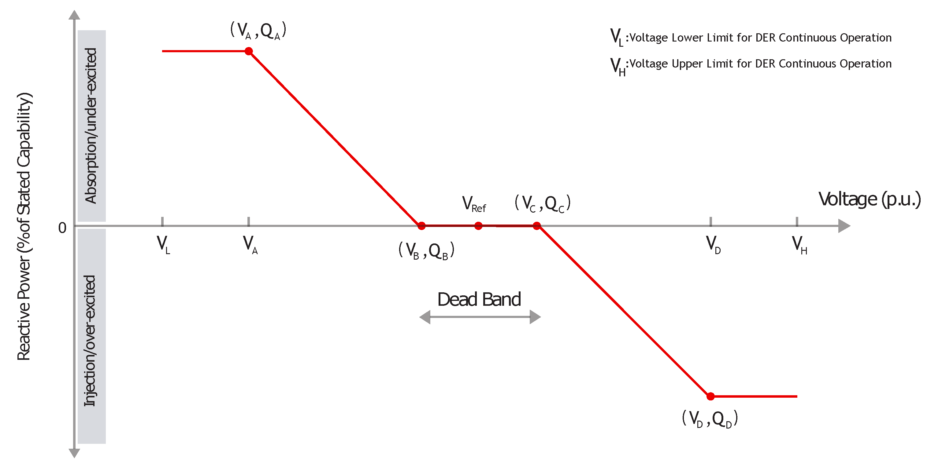
Voltage—Reactive Power Mode
The voltage—reactive power response mode varies the DER reactive power output in response to the voltage level. Following a voltage—reactive power linear characteristic as function of voltage, the DER should control its reactive power output (see
Figure 1 for an example of IEEE 1547 default parameters). BDEW specifies that the reactive power should be adapted between ten seconds and ten minutes.
Fixed Power Factor Mode
This mode may be required in some situations to meet network requirements. The network operator specifies the target power factor within the reactive capability requirements. AS 4777.2 establishes minimum thresholds from 0.8 leading to 0.8 lagging where the DER should operate if it is capable of operating at a fixed power factor; CEI 0-21 states the fixed power factor should be adjustable up to 0.9, and IEEE 1547 indicates that the power factor target shall not exceed the reactive power capability requirements. ARCONEL 003 [
20] does not require reactive capability requirements and only specifies that DER should try generating at a unity power factor. The difference between AS 4777.2 and CEI 0-21 numerical limits for fix power factor is 11%.
Power Factor—Active Power Mode
The characteristic power factor curve for cos (P) varies the DER power factor in response to changes in the DER output power. This aspect can also be considered as a reactive power displacement rather than a power factor. Following a linear piecewise active—reactive power characteristic as function of its active power output, the DER should control its reactive power output. Only two of studied standards addresses this topic. AS 4777.2 establishes displacement power factor thresholds from 0.9 leading to 0.9 lagging, and BDEW specifies that the reactive power should be adapted within ten seconds.
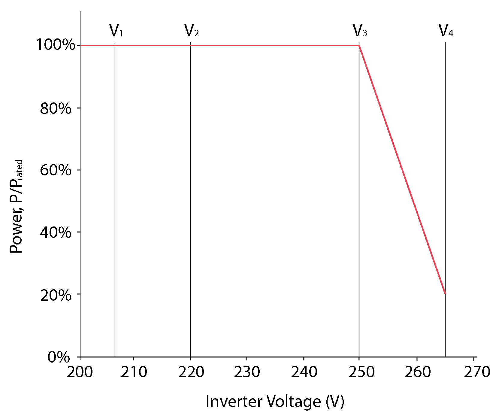
Voltage—Active Power Mode
The voltage—active power response mode varies the DER output power in response to the voltage level at its terminal. Following a voltage—active power linear characteristic as function of the voltage, the DER should limit its maximum active power (see
Figure 2 for AS 4777.2 default values). This function may be needed in low-voltage networks with very resistive impedance ratios, typically in very long feeders. None of the other studied standards addresses this topic.
4.2.2. Dynamic State (Voltage Support)
“Dynamic network support means voltage control in the event of voltage drops within the high and extra-high voltage network with a view to avoiding unintentional disconnections of large feed-in power, and thus network collapse [
3].” The intention is to avoid degradation in the quality of the service provided by the network and to allow the safe operation of the transmission network in the presence of large DER penetration levels.
During a network fault, the DER should be able to feed reactive current to support the voltage and, in some cases, not absorbing more reactive power following fault clearance than preceding fault appearance [
3,
21].
These functional requirements at the dynamic state are presented in the literature by the acronyms LVRT (low voltage ride through) and HVRT (high voltage ride through), which therefore apply for both undervoltage and overvoltage deviations.
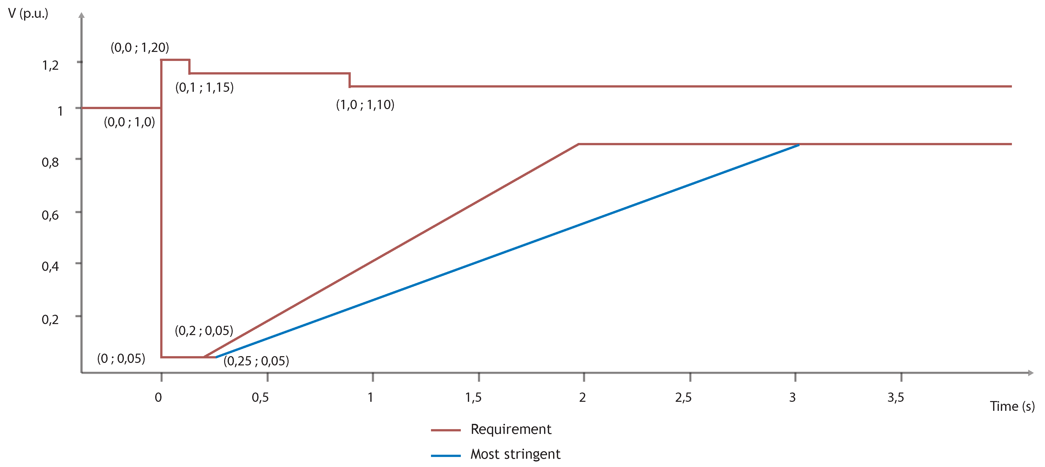
An example of LVRT and HVRT requirements is illustrated in
Figure 3 from the CLC/TS 50549-1 standard. Within the boundaries of the ride-through area, the generator should not disconnect from the grid at least within the time specified. Most standards only cover LVRT since HVRT is a concept included in CLC/TS 50549-1 [
22] and IEEE 1547 standards. Differently than the two aforementioned standards, BDEW, CEI 0-21, and GB-T 19964 only include requirements for LVRT, setting at 0 V the lowest value for the voltage boundary.
4.2.3. Restore Output after Ride Through
Another situation occurs when the DER rides through a voltage disturbance without tripping. Only the international standard IEEE 1547 addresses this topic of how to restore output considering whether dynamic support has been provided or not. If dynamic voltage support is not provided when the applicable voltage surpasses the lower value or returns below the upper value in LVRT and HVRT, respectively, the DER will maintain synchronism and restore the active current to at least 80% of the pre-disturbance active current level within 0.4 s. If DER provides dynamic voltage support, it will continue providing that support for up to 5 s.
4.3. Network Frequency Regulation and Support
When frequency disturbances within continuous operation exist, the DER may operate at reduced power output. The network operator may either require disconnect the DER or request a temporary limitation of the supplied power to avoid that a rise in frequency endangers the system’s stability. Six reviewed standards address this topic in
Table 6.
4.3.1. Steady State (Frequency Regulation)
To perform the frequency regulation, DERs typically use a frequency-droop (frequency-power) response, that is defined in Reference [
7] as a power variation of DER in a way that “shall reduce (for frequency increase) or increase (for frequency decrease) the active power generated instantaneously.” The active power gradient relative to the actual power may also define an active power droop; a droop of 2% means a power variation of 100% of P
M per Hz, in a 50 Hz base. The considered available power (P
M) is defined as the power value at which the frequency reaches the frequency regulation threshold.
In
Table 6, threshold values for the ranges of frequency into which DER shall respond are presented alongside the gradient between instantaneous power and frequency for this response. German VDE-AR-N 4105 and BDEW standards state that, between 50.2 Hz and 51.5 Hz, adjustable DER should vary P
M along a gradient of 40% per Hz. The frequency range thresholds in European standard CLC/TC 50549-1 are 50.2 Hz and 52 Hz, and the droop is adjustable between 2% and 12%. Chinese GB-T 19964 and European EN 50438 standards state the same threshold for overfrequency (50.2 Hz). Italian CEI 0-21 indicates an adjustable droop of 2%–12%, with a default value of 2.6%, from 50.2 Hz to 51.5 Hz, while EN 50438 establishes an active power gradient response of 42% with no delay. GB-T 19964 does not set any gradient value. Therefore, gradient differences among standards reach up to 60%.
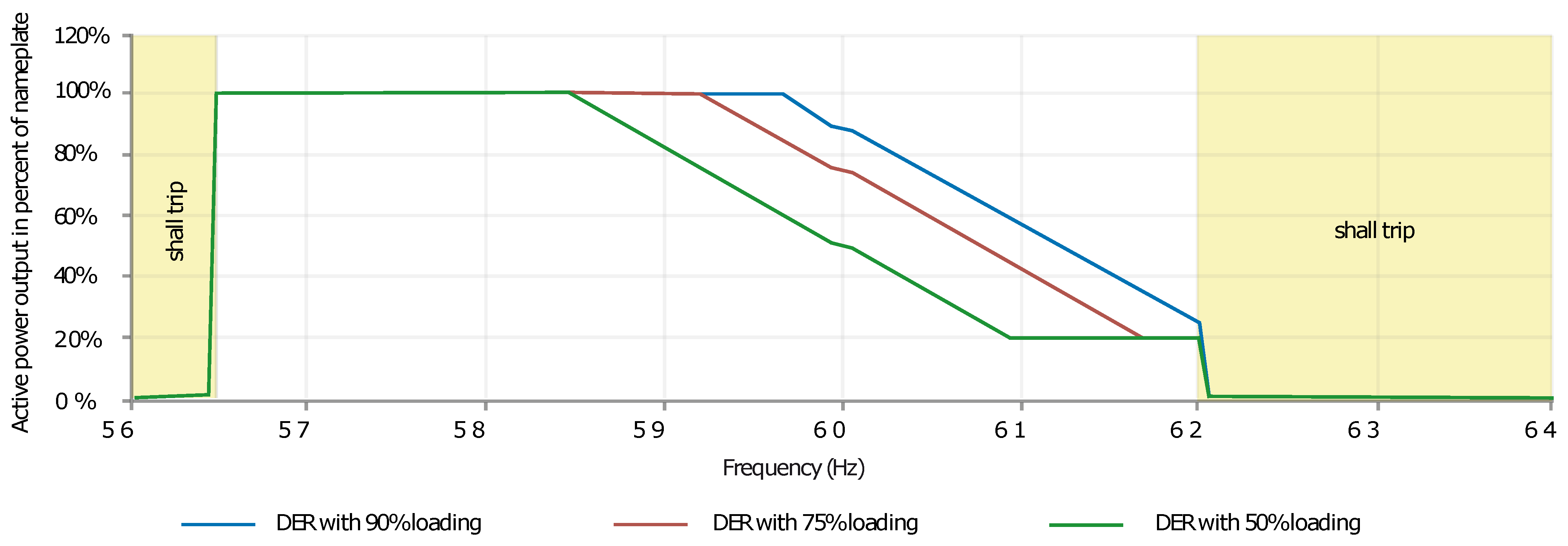
The default active power settings in case of underfrequency (value bellow 59.937 Hz) or overfrequency (value above 60.036 Hz), indicated in IEEE 1547, are depicted in Equations (
1) and (
2), respectively, where “
” refers to pre-disturbance active power. An example of 5% frequency droop is displayed in
Figure 4 [
18].
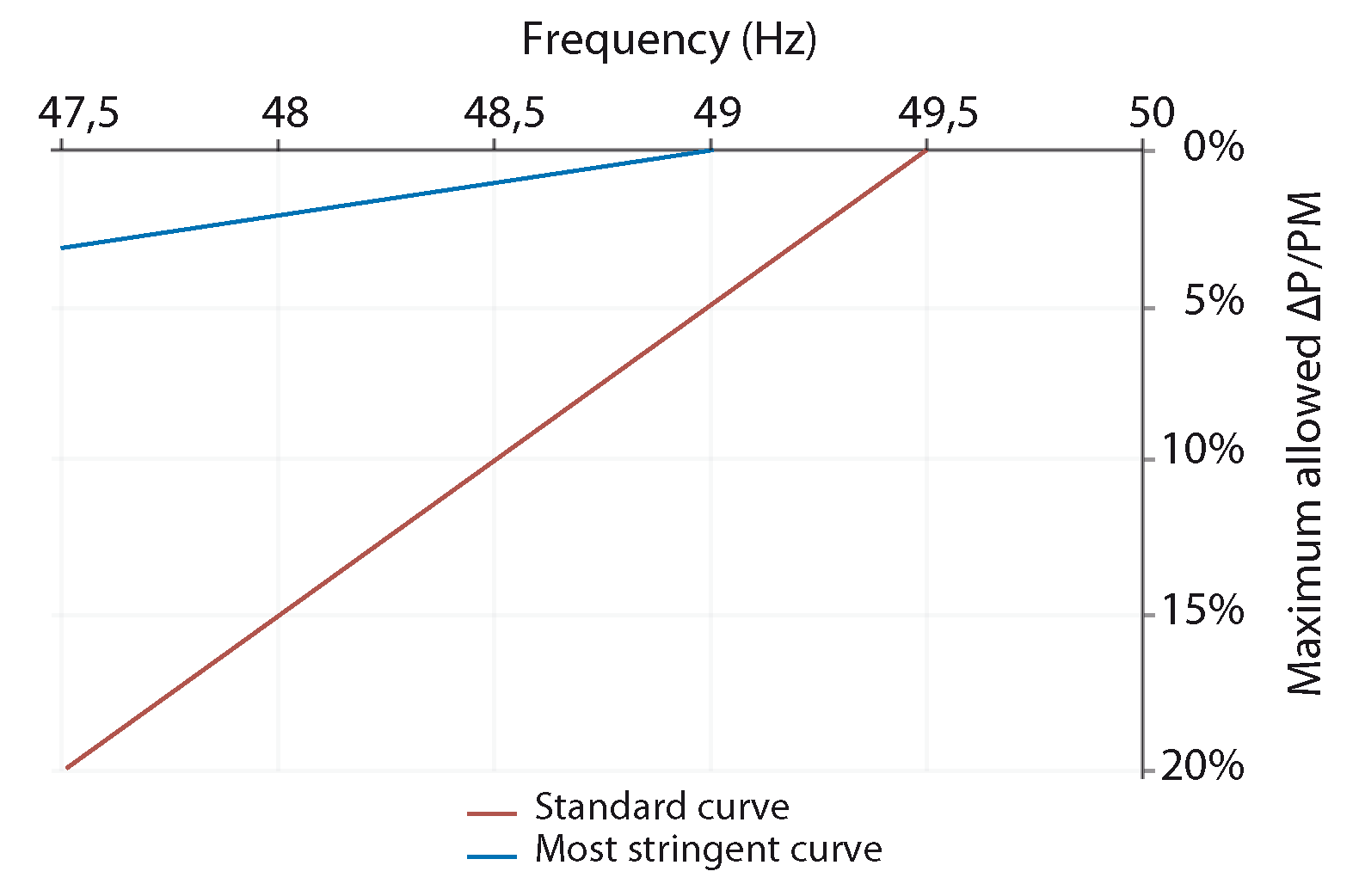
With another approach, CLC/TC 50549-1 states a maximum allowed reduction of active power by a reduction rate of 10% due to underfrequency below 49.5 Hz, indicated by a red line in
Figure 5. Additionally, a more stringent performance may be required for DER to be resilient to reductions of frequency due to underfrequency below 49.0 Hz with a maximum active power reduction rate of 2% (see
Figure 5, blue line).
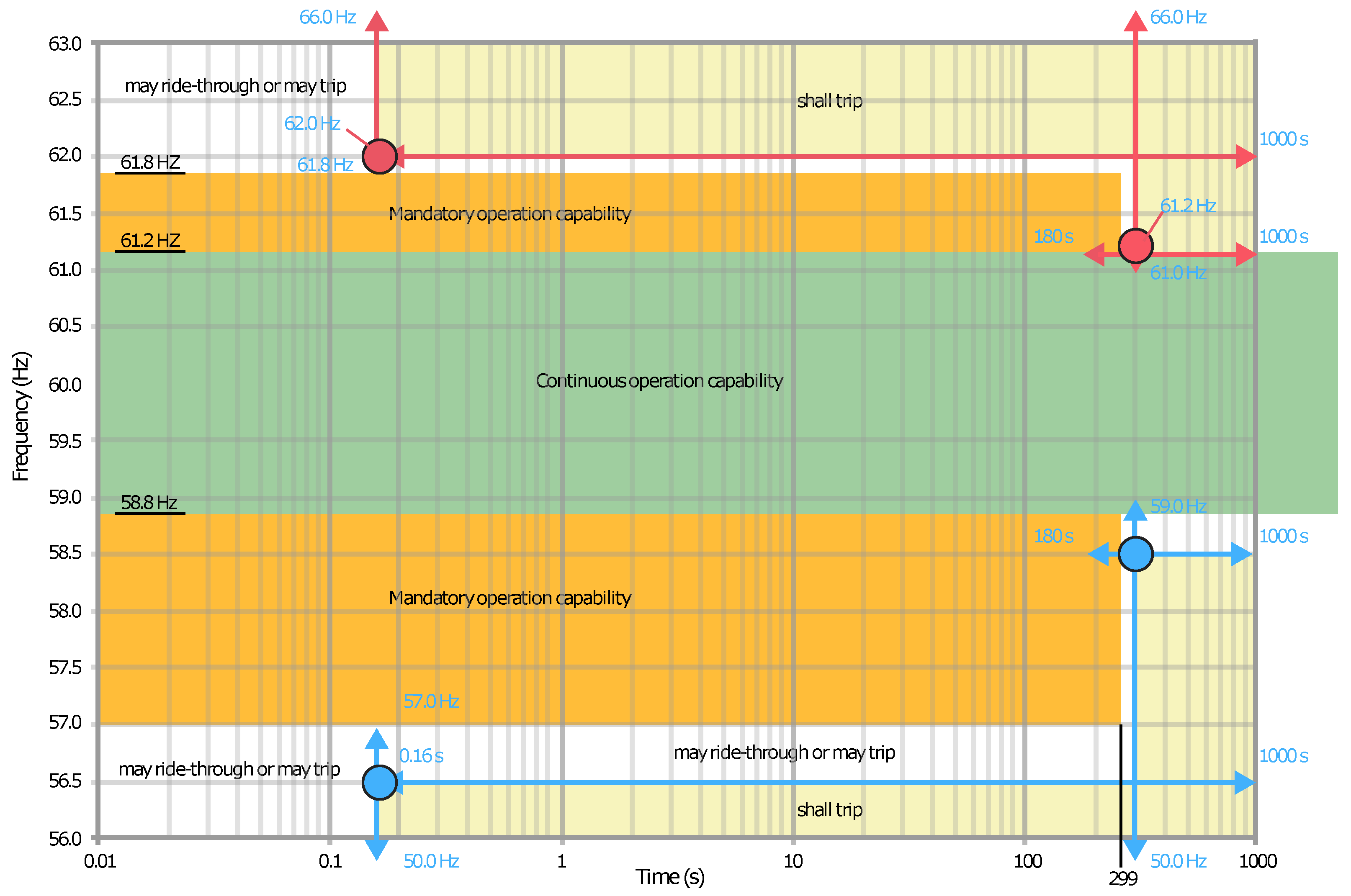
4.3.2. Dynamic State (Frequency Support)
The international standard IEEE 1547 is the only one to address this topic defining it as frequency ride through. This support is referred to frequency disturbances for which the system frequency remains between a given frequency range that shall not cause the DER to trip while maintaining synchronism. In addition, for low-frequency disturbances, the DER shall not reduce its active power below a specified value depending on the DER performance category (see
Section 3.1). This standard states ranges and default values for low-frequency and high-frequency disturbances of 61.2 <
f ≤ 61.8 and 57.0 ≤
f < 58.8, respectively, as well as 299 s for the trip time for Categories I, II, and III (see
Section 3.1,
Figure 6, and
Table 7).
Furthermore, the international standard IEEE 1547 defines the rate of change of frequency (ROCOF) ride through as a control capability, commonly used in the last few years as an anti-islanding protection by typically detecting network disconnection and island formation. However, this standard addresses the control function by detecting frequency gradient change within a time period and requesting the DER to ride through and not trip for frequency excursion with ROCOF magnitudes within specific ranges for each DER category (i.e., 0.5 Hz/s, 2 Hz/s, and 3 Hz/s for Categories I, II, and III, respectively).
Note that, if a generating unit protection trips instantaneously after its frequency falls below 57 Hz, it would be meeting the standard IEEE 1547 [
18] requirements (see
Table 7 and
Figure 6). This situation may result in an event such as those occurred eleven times in California between August 2016 and October 2017, where inverters erroneously tripped due to a transient event and instantaneous frequency measure during a power system fault. This problem could be alleviated by adding a time delay to ensure transient or distorted waveform ride through, as it is recommended in a dedicated NERC report named referring to the most significant power loss due to these inverter disconnection issues: “1200 MW Fault Induced Solar Photovoltaic Resource Interruption Disturbance Report [
23].”
4.4. Rate-of-Change of Power
The impact of abrupt changes in DER output can be maintained low by settling a limitation to the rate-of-change of power. The standard AS 4777.2 establishes that an inverter shall have an adjustable power rate limit that is set by default at 16.67% a minute, thus meaning a change of 100% in six minutes; it is acceptable to have two separate power rate limits to increase and decrease in output power. This limitation is used to smooth the DER output to avoid frequency excursions.
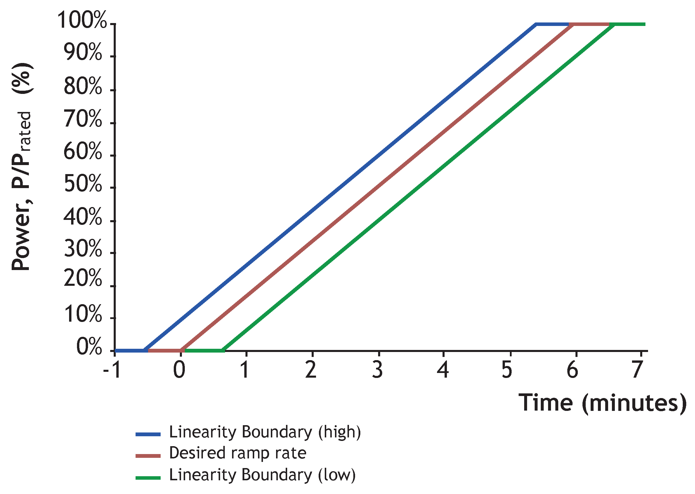
Non-linearity of power rate changes is defined as a maximum, permissible, discreet change in the power rate limit in response to a power output increase (see
Figure 7). The Australian standard AS 4777.2 exclusively addresses this topic and defines a non-linearity limit of 10%, calculated from one hundred times the allowed deviation from the characteristic curve and divided by the nominal ramp time in minutes.
4.5. Emulating Inertia
Replacing conventional generation with renewable sources leads to a loss of inertial response within the power system due to the lack of rotating masses in the case of photovoltaic or to the decoupling effect of the power electronics for wind energy conversion systems (WECS). Although this fact is well known, only two of the studied standards refer to this topic. Firstly, IEEE 1547 merely mentions “inertial response, in which the DER active power is varied in proportion to the rate of change of frequency, is not required but is permitted [
24].” Secondly, IEC 62898-1 states, “synthetic inertia can be emulated by several ways of generators and loads, not only by storage. It is an issue for a fast df/dt-controller [
11].”
5. Power Quality Conditions
To avoid power quality degradation of the energy supplied to the distribution network, limits must be established within the imbalance between phases, the harmonics content, the direct component of the current, and the voltage fluctuations.
5.1. Current Harmonics and Inter-Harmonics
Harmonics are distortions in the sinusoidal wave. When a sinusoidal oscillation frequency is an integer multiple of the fundamental, it is called harmonic (and not inter-harmonic) [
3]. Excessive harmonic distortion can cause adverse operation of customer and area EPS equipment. Harmonic contribution from DER can be difficult to predict. Furthermore, the same level of current harmonic from a DER may produce different voltage harmonic distortion levels depending on the area EPS characteristics.
Harmonic current injection into the network should not exceed the acceptable distortion limits stated in
Table 8 and
Table 9 while the DER supplies balanced linear loads [
5]. International IEC/IEEE/PAS 63547, IEEE 929, Australian/New Zealander AS/NZ 4777.2, Chinese GB-T 20046, and UL 1741 U.S. standards (
Table 8) indicate the allowable harmonic current in percent of the fundamental. Differently, German standards VDE-AR-N 4105 and BDEW (
Table 9) indicate allowable harmonic current in A per MVA. Moreover, BDEW differentiates by voltage connection level.
5.2. Permissible Imbalance
Voltage imbalance refers to the maximum unbalanced voltage that occurs between the lowest and highest phases.
In a balanced three-phase system, unbalanced loads shall entail unbalanced currents, which may also result in unbalanced voltages at this level due to derived voltage drops [
7].
These voltage and phase imbalance issues may be attenuated by utilizing three-phase DERs or by connecting multiple single-phase DERs evenly across all three phases [
12].
Only three standards address this topic; the British G59 states the connection should result in current and voltage imbalance below 17 kW or 16 A between phases, while German VDE-AR-N 4105 establishes an apparent power limit between phases of 4.6 kVA and adds that, if several single-phase DERs are connected to a PoC/PCC, “then uniform distribution of the power supplied to the three line conductors shall be aimed for [
7].”
Moreover, Australian/New Zealander standard AS/NZS 4777.2 establishes that the “output current for each phase for three-phase balanced system shall be within 5% of the measured value of the other phases at rated current when it is injected into a three-phase voltage [system] [
16].” Nevertheless, the standard allows DER to generate unbalanced currents if the inverter is used in a voltage balance mode (i.e., voltage balancing by injecting three-phase currents in an installation that presents an unbalanced load). If a voltage-balanced mode is available, it shall be disabled by default and shall be operated correctly with a single fault applied. In addition, 21.7 A is stated as the maximum current imbalance of three individual single-phase inverters [
16].
The studied standards addressing this topic provides the unbalance limit as percentage, current units, or power units, where differences reach 23% or 73%, respectively.
5.3. DC Current Injection
DC current injection is defined as the limitation of a DC injection output current into the AC interface at the PCC/PoC. Values indicated in the reviewed standards are presented in
Table 10. These limits range from 0.25% to 1%, with 0.5% of rated current being the most common value.
5.4. Limitation of Voltage Fluctuations
5.4.1. Flicker and Voltage Fluctuation
Flicker is characterized by frequency and amplitude voltage variations of a magnitude that may cause supplied lights to display disturbing brightness fluctuations [
3].
The subjective variation of light density in lamps is called flicker, and disturbances with an average value based on an interval of ten minutes is called short-term flicker strength. In a similar way, long-term flicker strength is based on a two-hour interval [
25]. In (
3), the long-term flicker strength of a generating unit
is estimated by a flicker coefficient value
c, times the generator apparent power output
divided by the short-circuit power
[
3]. Flicker limits indicated in studied standards are presented in
Table 11. In addition, IEC/IEEE/PAS 63547 states that the DER shall not create objectionable flicker, without defining any threshold value [
5].
5.4.2. Rapid Voltage Changes
Several standards cover the rapid voltage changes (RVC), requesting that the DER shall not cause step changes or ramp changes in the voltage at the PCC. VDE-AR-N 4105 indicates a limit value of 3% that should not be exceeded more than once every ten minutes. This limit is stated in IEEE 1547 at 3% of nominal voltage and 3% per second for a medium-voltage DER connection, 5% of nominal voltage, and 5% per second for a low-voltage DER connection [
26]. Differences between both standards for equivalent thresholds are around 40%.
The international standard IEEE 1547 states that RVC limits shall apply to sudden changes due to several causes such as: energization of transformers, frequent switching of capacitors, or abrupt output variations caused by DER malfunction. However, these limits shall not apply to infrequent events such as unplanned tripping or fault restoration.
6. Protection Capabilities
This section reviews general protection features established to ensure safe operation for personnel and equipment. DERs are usually required to provide protection functions such as over/short circuit current limitation, suitable grounding system scheme, and loss of mains detection to avoid unintentional island operation.
6.1. Short-Circuit Current
Both IEC/IEEE/PAS 63547 and Gazette of India: Part III-Sec.4 establish that energizing shall cease when short-circuit current occurs.
Moreover, BDEW states that the “network operator and the connection owner shall agree upon appropriate measures, such as limitation of the short-circuit current from the generating facility (e.g., by using its limiters)” [
3] and G83 states that the “manufacturer shall establish the maximum short circuit current contribution [
13].” Another standard covering this topic is CEI 0-21, which, for the purposes of equipment sizing, provides conventionally assumed values for the short-circuit current.
The expected short-circuit current value of the network must be incremented by the contribution of the DER. This contribution, as a multiplier of the rated current, can be considered to be: eight (synchronous generators), six (asynchronous generators), or one (inverter-based generators) [
7]. These values may be susceptible to utilization for accurate protection equipment adjustment.
6.2. Grounding
Only three of the reviewed standards cover the topic of grounding. IEEE 1547 states that the grounding scheme of the DER interconnection should neither prevent the ground—fault protection coordination nor entail overvoltages greater than the equipment rated voltage [
18]. Furthermore, UL 1741 standard indicates a grounding impedance with a maximum value of 0.1 Ohm [
27], while ARCONEL 003 specifies that the installation should be connected to a single and independent grounding system. In addition, this standard asserts that, between the photovoltaic system and the network, a galvanic separation is needed by an isolation transformer or any other suitable means [
20].
6.3. Anti-Islanding
One main problem related to the DER is the possibility that part of the network can be powered even when disconnected [
28,
29], thus creating an unintentional island. However, unintentional island situations can be detected using frequency-dependent characteristics [
17]. Then, the DER can be disconnected in order to avoid equipment damage caused by automatic reconnection without being synchronized.
Since frequency is a global variable related to all connected DERs, the requirements related to frequency are intended to guarantee the system overall stability and safety. These DERs should be capable to operate over a wide range of frequencies during a defined period to avoid a massive disconnection [
30]. They may even participate in the frequency control by means of a certain response to frequency deviations [
17].
Therefore, using frequency dependent characteristics for the detection of unwanted islands may not be effective while applying a wide operating frequency range and an active response to frequency deviation since a load-generation balance may occur [
22].
There are discrepancies not only in the way this issue is treated, but also in the limit values stated, for instance, ROCOF limit varies 62% between G59 and UL 1741.
Some reviewed standards combine the detection of unintentional islanding with overall system security needs through the inclusion of an intentional delay in the activation of the response to frequency deviations and the possible activation of a narrow frequency window (e.g., 49.8 Hz to 50.2 Hz) in case of a local event [
17]; the most commonly used methods are ROCOF and vector shift. Regarding ROCOF, G59 establishes a setting of 0.19 Hz/s from 47.5 Hz to 50.5 Hz. G83 indicates 0.2 Hz/s, while UL 1741 states 0.5 Hz/s, without defining a frequency window. Regarding vector shift, G59 and G83 establish 9 and 12 degrees, respectively. ARCONEL 003 exclusively indicates that the DER should disconnect from the network if it lacks power flow. In addition, IEEE 1547, IEC/IEEE/PAS 63547, VDE-AR-N 4105, Gazette of India Part: III-Sec.4, and GB-T 20046 add that an unintentional island should be detected and disconnected before a typically specified time of 2 s (5 s in VDE-AR-N 4105).
7. Intentional Island Operation and Microgrid Performance
Several standards consider the possibility that DER may intentionally operate in the intentional island operating mode, a planned electrical island as one of the key characteristics that defines a microgrid. The most significant standard addressing these new requirements is the recently updated IEEE 1547. In addition, international standards IEC 62898-1 and IEEE P2030.8 were released in 2017 and 2018, followed after by IEC 62898-3 [
31] in 2020.
During intentional island operation, CEI 0-21 indicates that frequency variations must remain within ±5% (and ±2% for 95% of the time), while slow voltage variations must remain within +10% and −15%. In addition, the G59 standard addresses this issue, requiring studies to be conducted for the intentional island mode of operation, so as to ensure the safety and stability of the system, as well as the quality of power.
In other words, equipment requirements must be established to detect that an island situation is needed and studies must be conducted to ensure that the isolated system is stable. In this regard, the German standard BDEW establishes that generating units, with capacity for island operation, in the presence of disturbances must participate in supporting the grid before disconnecting. According to IEC 62898-3 technical specifications, in islanded operation, energy storage systems shall be furnished to ensure stable operations during events such as excess of generation or loss of distributed generators. Furthermore, BDEW states that protection equipment must ensure all protective measures during isolated operation along with a recommendation to provide a synchronization device [
3]. Standard UL 1741 indicates for stand-alone inverters or converters that voltage magnitude must be within 10% of its rated output value, and that the output frequency shall be within 1 Hz of the rated output frequency. Finally, IEC/IEEE/PAS 63547 will consider this topic for future revisions.
In this regard, IEEE 1547 indicates the adjustments of several protection and control settings for DERs participating in an intentional island. Reactive power capability along with voltage and reactive power control settings remain the same as those for the connected mode (see
Section 4).
However, the settings for voltage trip, frequency trip, and frequency droop have different values than in the grid-connected mode. Trip time setting for overvoltage threshold 2 (as defined in
Table 2) shall range from 0.008 s to 0.16 s (
Table 12) rather than fixed at 0.16 s. Trip time for overfrequency threshold 1 and underfrequency threshold 1 (as defined in
Table 2) shall range from 11 s to 1000 s (
Table 12) rather than 180 s to 1000 s, with 300 s being the default. Regarding the frequency-droop performance of Category III (see
Section 3.1), the lower frequency droop value shall be 0.0055 p.u. (
Table 12) rather than 0.02 p.u. In addition, the same standard classifies the DER participating in intentional island mode into four categories: uncategorized, intentional island-capable, black start-capable, and isochronous-capable.
Moreover, international standard IEC 62898-2 defines a microgrid as a “group of interconnected loads and distributed energy resources with defined electrical boundaries that acts as a single controllable entity and is able to operate in both grid-connected and islanded mode [
32,
33].” The microgrid aims to improve reliability by islanding a distribution network part (e.g., campus, utility grid) or facility (e.g., hospital, military base, customer installation). In order to perform microgrid planning and operation, IEC 62898-2 indicates that generation forecast studies should be conducted. Furthermore, this standard specifies that both isolated microgrids and non-isolated microgrids operating in island mode must be self-sustaining, thus managing their load and satisfying it by the DER.
According to IEC 62898-2, the protection settings may be relaxed to provide a stable power supply because the microgrid might experience degradation of power quality in those modes of operation. In the case of microgrids operating in island mode which are served only by converter-based generators, the short circuit current is often low, so the generators might be able to provide sufficient current to operate an overcurrent protection device with a lower current setting [
31].
Regarding island operation several discrepancies have been found, for example, the difference in the frequency limit between CEI 0-21 and UL 1741 standards is 67%.
8. Proposed Unified Standard Structure
A standard is an industry consensus mechanism to establish what is required to comply with, preserving “a balance between being prescriptive and providing a wide latitude to users to choose from a range of options to better meet the requirements of a given application [
2].”
Throughout this article discrepancies among standards have been commented section by section, highlighting the need for a clear and unified international regulation, that would help to reduce risks and uncertainty, such as those related to events occurred between August 2016 and October 2017 in southern California [
34], where inverters erroneously tripped due to a transient event and instantaneous frequency measure during a power system fault [
23], as it has been described in
Section 4.3.2.
Currently, there exist national and international standards and a manufacturer may not have a clear guidance to follow, mainly when there are different criteria. Regarding to the aforementioned events, NERC report explains that solar development owners are subject to National Electric Code (NEC) which requires UL 1741 certification. To be certified, inverters shall accomplish IEEE 1547 standard, that is in conflict with the NERC relay settings standard. This report concludes: “This is a challenge for solar development owners. If there were a utility scale transmission standard that a UL 1741 testing and certification could be based on, that may alleviate this challenge [
23].”
Therefore, TSOs/DSOs and inverter manufacturers need a global regulatory framework and standard. This research does not intend to fully solve this problem but it does emphasize those differences. It seems necessary that stakeholders hold meetings to share criteria based on feedback from experience in order to develop a unified standard which also benefit owners of solar PV power plants, distribution/transmission planners and operators as well as planning/reliability coordinators. Hence, the standard development process should integrate not only inverter manufacturers, consultants and service providers, but also TSOs/DSOs, utilities, and research/standardization entities.
Finally, to assure clarity for the new unified standard, the authors recommend it to contain at least the key aspects identified by performing a comprehensive analysis throughout 23 standards, resulting in a proposed structure presented in
Table 13. The unified standard, as any other, might be dynamic, but in the long term should tend to converge to stable requirements and values.
9. Conclusions
This research has presented an analysis and comparison of 23 of the main standards related to DER and microgrids. The analysis and comparison focus on the next found topics: interconnection criteria, operating conditions, control capabilities, power quality, protection functions, and reference variables, being IEEE 1547 the most complete standard. Significant differences have been found between the standards, as an example in the operating conditions section are differences of up to 40% in the equivalent threshold settings for over-low voltage and 2.8 Hz for over-low frequency.
Among all the revised standards, nine assume that part of the distribution network remains in operation when disconnected from the main network (intentional island or an isolated microgrid mode), including the four recent microgrid specific standards (IEC 62898-1, IEC 62898-2, IEEE P2030.8 and IEC 62898-3).
The incorporation of the following concepts in the standards is quite heterogeneous: emulation of inertia (only two of the standards address the issue), the non-linearity of power rate changes (only treated by the Australian standard AS 4777.2), or frequency ride through (only in IEEE 1547). In addition, only a few standards incorporate specific concepts such as categorizing the DER, the priority of the response modes, or rapid voltage changes. Most standards exclusively cover low voltage ride through capability as high voltage is a concept only recently included.
Therefore, it seems there exists a clear need to define a common framework for DER and microgrid standards in the future, wherein topics, terminology, and values are expressed in a manner that may widely cover the entire diversity in a way similar to how it has already been expressed at the network transport level by the ENTSO-E codes or the proposed unified structure.
Author Contributions
Conceptualization, M.C. and D.S.-M.; methodology, M.C. and D.S.-M.; validation, D.R., M.C.-R., M.C., and D.S.-M.; formal analysis, D.R. and M.C.-R.; investigation, D.R.; resources, M.C.-R. and D.R.; data curation, D.R. and M.C.-R.; writing—original draft preparation, D.R. and M.C.-R.; writing—review and editing, M.C. and D.S.-M.; visualization, D.R., D.S.-M.; supervision, D.S.-M. and M.C.; project administration, D.R., and D.S.-M. All authors have read and agreed to the published version of the manuscript.
Funding
This research received no external funding.
Institutional Review Board Statement
Not applicable.
Informed Consent Statement
Not applicable.
Data Availability Statement
Not applicable.
Acknowledgments
Juan Carlos López Benalcázar, ELECGALÁPAGOS S.A., Ecuador; Josep M. Guerrero, Aalborg University, Denmark; Pedro Paes, EDP Energias de Portugal, Portugal.
Conflicts of Interest
The authors declare no conflict of interest.
References
- Wu, Y.; Lin, J.; Lin, H. Standards and Guidelines for Grid-Connected Photovoltaic Generation Systems: A Review and Comparison. IEEE Trans. Ind. Appl. 2017, 53, 3205–3216. [Google Scholar] [CrossRef]
- Joos, G.; Reilly, J.; Bower, W.; Neal, R. The Need for Standardization: The Benefits to the Core Functions of the Microgrid Control System. IEEE Power Energy Mag. 2017, 15, 32–40. [Google Scholar] [CrossRef]
- Guideline for Generating Plants’ Connection to and Parallel Operation with the Medium-Voltage Network; Bundesverband der Energie-und Wasserwirtschaft (BDE): Berlin, Germany, 2010.
- Recommended Practice for Utility Interface of Photovoltaic Systems; IEEE 929-2000; The Institute of Electrical and Electronics Engineers (IEEE): Piscataway, NJ, USA, 2000.
- Interconnecting Distributed Resources with Electric Power Systems; IEC/IEEE/PAS 63547-2011; The International Electrotechnical Commission (IEC): Geneva, Switzerland; The Institute of Electrical and Electronics Engineers (IEEE): Piscataway, NJ, USA, 2011.
- Grid Connection of Energy Systems via Inverters Part 1: Installation Requirements; AS 4777.1-2016; Council of Standards Australia: Sydney, NSW, Australia, 2016.
- Power Generation Systems Connected to the Low-Voltage Distribution Network—Technical Minimum Requirements for the Connection to and Parallel Operation with lOw-Voltage Distribution Networks; VDE-AR-N-4105-2011; Association for Electrical, Electronic & Information Technologies (VDE): Frankfurt am Main, Germany, 2011.
- Technical Standard for Connectivity of the Distributed Generation Resources; Gazette of India. Part III-Sec.4-2013; Indian Central Electricity Authority: New Delhi, India, 2013.
- Reference Technical Rules for the Connection of Active and Passive Users to the LV Electrical Utilities; CEI-0.21-2019; Italian Electrotechnical Committee: Milano, Italy, 2019.
- Technical Requirements for Connecting Photovoltaic Power Station to Power System; GB/T 19964-2012; Standardization Administration of the P.R.C.: Beijing, China, 2012.
- Microgrid—Part 1: Guidelines for Microgrids Planning and Specification; IEC 62898-1-2017; The International Electrotechnical Commission (IEC): Geneva, Switzerland, 2017.
- Recommendations for the Connection of Generating Plant to the Distribution Systems of Licensed Distribution Network Operators; G59-2014; Energy Networks Association: London, UK, 2014.
- Recommendations for the Connection of Type Tested Small-Scale Embedded Generators (up to 16 A per Phase) in Parallel with Low-Voltage Distribution Systems; G83-2012; Energy Networks Association: London, UK, 2012.
- Photovoltaic Systems—Characteristics of the Utility Interface; GB/T 20046-2006; Standardization Administration of the P.R.C.: Beijing, China, 2006.
- Requirements for Connecting to the Power System. Part 1: Grid-Connected Inverters; UNE 206007-1:2013; Spanish Association of Standarization (UNE): Madrid, Spain, 2013.
- Grid Connection of Energy Systems via Inverters Part 2: Inverter Requirements; AS 4777.2-2015; Council of Standards Australia: Sydney, Australia, 2015.
- Requirements for Micro-Generating Plants to be Connected in Parallel with Public Low-Voltage Distribution Networks; AS 4777.2-2015; European Committee for Electrotechnical Standardization: Brussels, Belgium, 2015.
- Standard for Interconnection and Interoperability of Distributed Energy Resources with Associated Electric Power Systems Interfaces; IEEE 1547-2018; The Institute of Electrical and Electronics Engineers (IEEE): Piscataway, NJ, USA, 2018.
- Standard Conformance Test Procedures for Equipment Interconnecting Distributed Energy Resources with Electric Power Systems and Associated Interfaces; IEEE 1547.1-2020; The Institute of Electrical and Electronics Engineers (IEEE): Piscataway, NJ, USA, 2020.
- Microgeneración Fotovoltaica para Autoabastecimiento de Consumidores Finales de Energía Eléctrica; ARCONEL 003-2018; Agencia de Regulación y Control de Electricidad (ARCONEL): Quito, Ecuador, 2018.
- Boemer, J.C. On Stability of Sustainable Power Systems. Network Fault Response of Transmission Systems with very High Penetration of Distributed Generation. Ph.D. Thesis, Delft University of Technology, Delft, The Netherlands, 2016. [Google Scholar]
- Requirements for Generating Plants to be Connected in Parallel with Distribution Networks—Part 1: Connection to a LV Distribution Network—Generating Plants up to and Including Type B; CLC 50549.1-2019; European Committee for Electrotechnical Standardization (CENELEC): Brussels, Belgium, 2019.
- 1200 MW Fault Induced Solar Photovoltaic Resource Interruption Disturbance Report. Southern California 8/16/2016 Event; New Mexico 87185 and Livermore: Albuquerque, CA, USA, 2017; pp. 1–38.
- Jenkins, N.; Thornycroft, J. McEvoy’s Handbook of Photovoltaics. Fundamentals and Applications; Academic Press, Elsevier: Amsterdam, The Netherlands, 2018. [Google Scholar]
- Stieberg, M. Wind Energy Systems for Electric Power Generation; Springer: Berlin/Heidelberg, Germany, 2008. [Google Scholar]
- Xavier, J. Protection & Control strategy for effectively interconnecting and islanding Distributed Energy Resources during grid disturbances. In Proceedings of the 2019 72nd Conference for Protective Relay Engineers (CPRE), College Station, TX, USA, 25–28 March 2019. [Google Scholar]
- Inverters, Converters, Controllers and Interconnection System Equipment for Use with Distributed Energy Resources; UL 1741-2005; Underwriters Laboratories (UL): Brook, IL, USA, 2005.
- Belloni, F.; Groppelli, P.; Chiappa, C.; Chiumeo, R.; Gandolfi, C. Test of anti-islanding protections according to IEC 62116: An experimental feasibility assessment. In Proceedings of the IEEE 2013 48th International Universities’ Power Engineering Conference (UPEC), Dublin, Ireland, 2–5 September 2013; pp. 1–6. [Google Scholar]
- Delfanti, M.; Frosio, L.; Merlo, M.; Monfredini, G.; Pandolfi, L.; Rosati, C.; Rosati, D. Dispersed generation to provide ancillary services: AlpStore project. In Proceedings of the 2013 International Conference on Clean Electrical Power (ICCEP), Alghero, Italy, 11–13 June 2013. [Google Scholar]
- Šperlín, I.; Gurecký, J. Advanced functions of network support based on ENTSO-E NC RFG in the czech technical standards. In Proceedings of the 2016 17th International Scientific Conference on Electric Power Engineering (EPE), Prague, Czech Republic, 16–18 May 2016. [Google Scholar]
- Microgrids—Technical Requirements—Protection and Dynamic Control; IEC 62898-3-1-2020; The International Electrotechnical Commission (IEC): Geneva, Switzerland, 2020.
- Microgrids—Part 2: Guidelines for Operation; IEC 62898-2-2018; The International Electrotechnical Commission (IEC): Geneva, Switzerland, 2018.
- Madtharad, C.; Chinabut, T. A literature review of Microgrids: A functional layer based classification. In Proceedings of the 2018 53rd International Universities Power Engineering Conference (UPEC), Glasgow, UK, 4–7 September 2018. [Google Scholar]
- Ross Guttromson, M.B. Improving Dynamic Performance and Modeling of Utility-Scale PV Systems During Grid Disturbances; SAND2020-0266; Sandia National Laboratories: Albuquerque, NM, USA; Livermore, CA, USA, 2020; pp. 1–27. [Google Scholar]
| Publisher’s Note: MDPI stays neutral with regard to jurisdictional claims in published maps and institutional affiliations. |
© 2021 by the authors. Licensee MDPI, Basel, Switzerland. This article is an open access article distributed under the terms and conditions of the Creative Commons Attribution (CC BY) license (http://creativecommons.org/licenses/by/4.0/).


