Abstract
In the present study, a nozzle was used to improve the flow performance of an intake manifold, and its effects on the automobile engine output and the exhaust gas were experimentally studied. It was found that the engine output of a vehicle with a mileage of 30,000 km increased by 4.7% and 6.5% when nozzles with diameters of 5 and 2.5 mm were used. In addition, the engine output of a vehicle with a mileage of 180,000 km increased by 3.3% and 13.3% when nozzles with diameters of 5 and 2.5 mm were used compared to those of the same vehicle when no nozzle was used. Thus, using a nozzle for the inflow of outside air created a uniform combustion environment to improve the engine output and reduce harmful exhaust gases, such as hydrocarbon, carbon monoxide, and nitrogen oxides, by generating vortexes inside the intake manifold and increasing the degree of mixing. Furthermore, the smaller nozzle with a diameter of 2.5 mm had greater effects.
1. Introduction
Since the industrial revolution, scientific technologies have developed rapidly, and various technologies are continuously developing today to make human life comfortable. Starting with the steam engine of James Watt, in particular, the automobile has greatly widened the scope of human activities, and the demand for automobiles has continued to grow since the invention of the gasoline engine. Moreover, most modern households have at least one vehicle, which has become an indispensable item in our lives. However, exhaust gases emitted after combustion from automobiles that use fossil fuels contain various pollutants, which adversely affect the human body and pollute the atmosphere, causing many environmental problems. In addition, since the emission of greenhouse gases, including carbon dioxide, is inevitable after combustion, global warming is accelerating. For this reason, every country is increasingly interested in the problem of environmental pollution caused by automobile exhaust gases and is strengthening regulations on emissions. For example, in the EU, EURO 6, which is stricter than the automobile emission regulations enforced earlier (EURO 1 to 5), has been enforced since 2014 [1], and such automobile emission regulations are being continuously strengthened.
Currently, one of the most harmful substances in the exhaust gas emitted from a gasoline engine is carbon monoxide (CO), which is generated through incomplete combustion. As CO interrupts the transport of oxygen in the blood due to its hemoglobin affinity, which is 300 times higher than that of oxygen, people who inhale air containing 0.3% or more CO by volume for a long time can lose their lives [2,3]. In addition, the exhaust gas emitted during incomplete combustion also includes hydrocarbon (HC), which is mainly generated in fuel-rich combustion conditions such as those that generate CO. HC affects the respiratory system at low concentrations, and the aldehydes produced by the primary oxidation of HC affect mucous membranes and skin. When the HC is oxidized further, peroxides are generated. These peroxides combine with nitrogen oxides (NOx) to produce photochemical smog, which severely affects the eyes, causes cancers, or leads to malodorous air [4,5,6]. Lastly, NOx compounds are produced through the reaction of nitrogen in the air with oxygen in the special environment inside the engine, and these gases are toxic and have an irritating odor. In particular, when it is adsorbed onto mucous discharges through respiration, nitric acid, which has strong oxidizability, is produced, and NOx is the main substance that causes global warming. Accordingly, various studies are conducted around the world to reduce automobile exhaust gases, and regulations on various forms of environmental pollution are being strengthened.
For this reason, studies to reduce the exhaust gases emitted from automobiles are actively conducted. First, in an analytical study related to the reduction in automobile exhaust gases, Kim et al. [7] comparatively verified the flow distribution characteristics of the intake manifold NU base, low/medium-speed primary model, low/medium-speed secondary model, NU hybrid electric vehicle (HEV), and Gamma gasoline direct injection (GDI) through computational analyses and tested their distribution. Based on their distribution tests, the authors reported that all of the models satisfied the design standard of ±2.5% and that four models, excluding the NU HEV model, satisfied the distribution design standard of ±2.5%. Park et al. [8] evaluated the distribution by the cylinder of the target engine using a commercial 1D engine simulator and a 3D flow analysis program. The results confirmed that the flow deviation decreased from 13% to 1.6%, depending on the manifold structure and the inlet location. Through a flow analysis for the minimization of the engine’s intake flow resistance and the distribution of the intake flow among cylinders, Kim et al. [9] found that the external center-feeding method could reduce pressure loss and speed loss compared to those obtained with the internal center-feeding method. In addition, Kim et al. [10] analyzed the flow distribution characteristics depending on the manifold configuration using computational fluid dynamics (CFD) and found that it is important to minimize the local pressure drop when designing a manifold. Kim et al. [11] carried out an analysis on the flow structure inside a distribution manifold related to flow distribution performance in turbulent flow conditions and found that the pressure difference at the inlets of the center-feed model and the side-feed model of the Gamma gasoline direct injection (GDI) intake manifold and the NU multipoint injection (MPI) intake manifold was proportional to the size of the bell mouth. Beatrice et al. [12] performed an experimental study on a prototype diesel injector with a hollow cone nozzle to analyze engine exhaust performance and spray structures. Their results confirmed that injector command parametrization, particularly the charging voltage or needle lift, only partially affected engine performance. Lee et al. [13] carried out an analytic study in which the shape of the outlet port was changed to improve the performance of a flow distribution manifold in turbulent flow conditions and found that the longer the outlet port and the smaller the area ratio, the more uniform the distribution of the outflow rate. In addition, after conducting an analytical study on the performance optimization of a diesel engine equipped with composite-type exhaust gas recirculation (EGR), Park et al. [14] reported that the optimal model achieved the same level of torque and fuel efficiency as those of a high-pressure-type EGR model and a nitrogen oxide reduction efficiency of 40% on average. Zhang et al. [15] conducted a study to improve disturbance removal and control accuracy in a diesel engine. A simulation showed that the proposed nonlinear extended state observer (NLESO) controller had better response performance and resistance to external disturbances. Bondar et al. [16] developed a mathematical model of the thermodynamic operating process in the intake manifold of a diesel engine using fuel and water injection. Using the developed model, appropriate design parameters for the fuel and water injection system were determined. Shen et al. [17] evaluated the trapped exhaust gas distribution in a diesel intake system using Star-CD software. Their results showed that, during the intake process at the intake port without a CO2 supply, CO2 mass flow rates of 5 and 50 kg/h produced CO2 levels of 4% and 10%, respectively.
In a study on the reduction in automobile exhaust gases, Hwang et al. [18] carried out experiments on the reduction in NOx by a lean NOx trap (LNT) catalyst through fuel injection control of a passenger car diesel engine. They reported that NOx was more effectively reduced when the throttle position and the injection timing were controlled simultaneously compared with controlling only the throttle position to recycle the LNT catalyst. Kwon et al. [19] analyzed the effect of a change in the driving conditions of a gasoline vehicle on fuel efficiency. They found that the deviation was as large as 3.44% depending on the state of charge (SOC) and the operating state of the alternator, and the test deviation was about 1.3% under the extreme conditions of the upper limit (29 °C). The lower limit (21 °C) depended on changes in laboratory temperature conditions. Lee et al. [20] examined the NOx emission characteristics of vehicles in response to seasonal changes and found that the emission of NOx was relatively high at a high intake air temperature (35 °C) or a low intake air temperature (−7 °C) compared to that at the ordinary intake air temperature (25 °C). Jang et al. [21] measured the exhaust gas emitted on a real road in real time and found that the amount of NOx emitted on the road was higher than the emission standard in the test mode of the chassis dynamometer. Alasfour [22] examined the effect of ignition timing (20/23/27 °C BTDC) on exhaust gas NOx and thermal efficiency using an isobutane–gasoline mixture in an ignition engine. As a result, they found that moving up the ignition timing increased the thermal efficiency and NOx emission. Topgül et al. [23] examined the effects of unleaded gasoline and an unleaded gasoline–ethanol mixture on the engine performance and exhaust gas at various ignition times and found that, although a delayed ignition time reduced the exhaust gas temperature and effective electric power, it increased fuel consumption and HC and CO emissions. Zsiga et al. [24] conducted a study to implement intake manifold boosting in an SI engine with the aim of effectively overcoming turbo lag. They reported that intake manifold boosting effectively overcame turbo lag, but the air mass consumption was 2.3–4.6 times higher than that of the in-cylinder bushing, requiring an additional compressor.
In addition, Rahman et al. [25,26] established the latest strategies and experimental methods to reduce emissions from automobiles. As a result, they determined that the emission of NOx could be reduced by delaying the injection timing. In addition, they reported that the existing engine emission test and vehicle chassis dynamometer test results showed significant differences from on-road emission test results, which led researchers to prioritize road emission testing. Sayin et al. [27] conducted a study on the effect of ignition timing on combustion and exhaust gas using gasoline with different octane numbers and reported that the fuel consumption and thermal efficiency of high-grade RON gasoline (RON 97 and RON 98) were improved as a result of improved ignition timing. In addition, they reported that improved ignition timing could reduce CO and HC emissions in the case of fuel with a high octane number. In a study on the effect of an ethanol–gasoline mixture on CO and HC emissions in the latest generation of a spark-ignition (SI) engine in cold-start transient conditions, Iodice et al. [28] found that CO and HC emissions during a cold start were reduced in comparison to those of commercial gasoline, and a 20% ethanol mixture showed the largest emission reduction. Dardiotis et al. [29] examined the gas emission of latest-technology passenger cars during a cold start and found that the CO and total HC emissions from gasoline vehicles at 617 °C increased by 2.3–11.3 times during an urban driving cycle (UDC). In a study on the use of a diverging-tapered-hole nozzle for GDI engine applications, Moon et al. [30] found that the diverging-tapered-hole nozzle combined with an appropriate hole length promoted the generation and dispersion of spray particles outside the nozzle by forming a flow structure in the shape of a crescent moon that expanded radially from the hole. Wang et al. [31] used a nonlinear compensation method to enhance the spray control accuracy of a sprayer and optimize the exhaust gas of a GDI engine and found that the injection error in a small flow area could be controlled within 10%. Blasio et al. [32] conducted a study on a flexible advanced fuel injection system to meet future CO2 goals in ultralight and medium-sized diesel engines. They confirmed the benefits of using high fuel injection pressures to decrease peak firing pressures by combining competitive performance and good fuel economy with the emissions, noise, vibration, and harshness requirements of last-generation diesel engines for passenger car applications. Miganakallu et al. [33] investigated the performance of a GDI engine when a water–ethanol mixture was used and compared it with cases when pure water or pure ethanol was used. The results showed that the spray of water or a water–ethanol mixture improved the combustion stability of the engine and reduced the exhaust gas temperature.
Most previous studies have focused on changing the ignition timing, using a mixture, or changing the intake manifold configuration to improve the engine output or reduce the exhaust gas, and such methods have the disadvantages of requiring a complex configuration and high economic costs. Accordingly, solving such problems first requires a change in the manifold configuration, of which a structural change is simple and effective. Therefore, in the present study, to improve the combustion performance through a simple structural change of the intake manifold, a method in which a nozzle in the intake manifold is used to increase the flow rate of the air sucked in with outside air was devised. However, the air inside the intake manifold may flow out through the nozzle when not driving. A sensor and a valve device that control the inflow of air at a traveling speed of less than 30 km/h are required. In this study, after installing a nozzle in vehicles with mileages of 30,000 and 180,000 km, the engine outputs were measured, and the performance was compared. In addition, the effects of the nozzle used on the major exhaust gases of the automobile were investigated in the ASM2525 mode [34], which is an actual vehicle exhaust gas inspection method. The present study is expected to contribute to performance improvement and exhaust gas reduction in existing automobiles by using a simple structural change of the intake manifold without high costs.
2. Modeling and Simulation Conditions
In this study, a nozzle for outside air supply was used to improve the flow performance of the intake manifold. The shape of the intake manifold with the nozzle was modeled using CATIA software, and flow simulation was performed using ANSYS Fluent. Nozzles with diameters of 2.5 and 5 mm were used, and the model of the intake manifold with the nozzle is shown in Figure 1. In addition, when the engine speed was 2000 rpm, the nozzle flow velocity was applied based on the vehicle speed, and the flow simulation of the intake manifold was performed according to the change in the nozzle angle. The intake manifold used in this study is based on a 2000 cc gasoline vehicle, and the simulation conditions are shown in Table 1.
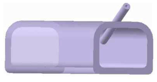
Figure 1.
Model of intake manifold using a nozzle.

Table 1.
Simulation conditions of intake manifold using a nozzle.
3. Experimental Setup and Method
3.1. Experimental Setup
In the present study, a 2000 cc gasoline engine with a mileage of 30,000 km and an old 2000 cc gasoline engine with a mileage of 180,000 km were used. The photographs and detailed specifications of the vehicles used in the present study are shown in Figure 2 and Table 2. To analyze the effect of the air inflow on the engine performance and the exhaust gas, a 2.5 or 5 mm nozzle was inserted into the intake lines of the intake manifold. In addition, the pressure was adjusted by utilizing a pressure regulator to exert the effect of the vehicle’s front speed during driving on the nozzle. Figure 3 shows photographs of the intake manifolds in which the nozzles produced in the present study were installed.
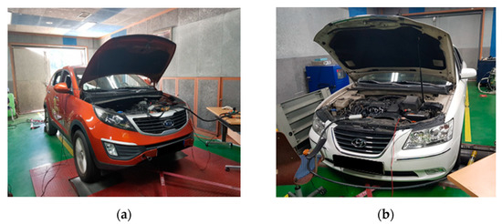
Figure 2.
Photographs of experimental setup using 30,000 and 180,000 km mileage cars. (a) Vehicle mileage: 30,000 km; (b) vehicle mileage: 180,000 km.
Table 2.
Specifications of gasoline engines.
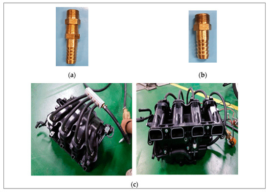
Figure 3.
Photographs of nozzles on the intake manifold. (a) Nozzle diameter: 2.5 mm; (b) nozzle diameter: 5 mm; (c) installed test setup.
In the present study, the outside air flowing into the intake manifold through the installed nozzle was arranged to flow in with an increased flow rate so that the hydrocarbon, carbon monoxide, and nitrogen oxide in the exhaust gas could be reduced by vortexes such as swirls and tumbles in the intake system of the engine, which form as a result of increases in the airflow rate and the amount of the air sucked in. If the gases are well mixed within a short time due to the use of a nozzle, the fuel efficiency can be improved as the combustion stability improves, thereby not only improving the combustion speed but also reducing the percentage of the fuel that is emitted in its original form without being combusted during the combustion process. In addition, improvement in fuel efficiency is closely related to the reduction in various pollutants generated during combustion.
In addition, in the present study, the performance of the engine was measured using a chassis dynamometer to determine the effect of using a nozzle in the intake manifold on the output of the vehicle. A chassis dynamometer is a device built to replicate the driving conditions of an actual vehicle while allowing it to be tested under a uniform load condition by applying a constant force to the wheels of the vehicle to reproduce the deceleration conditions of a vehicle on the road. Table 3 shows the details of the chassis dynamometer. In addition, in the present study, the exhaust gases (HC, CO, and NOx) emitted from the vehicles were measured while the vehicles were operated on the chassis dynamometer in the ASM2525 mode. Table 4 shows the details of the exhaust gas measuring instrument.
Table 3.
Specifications of chassis dynamometer.
Table 4.
Specifications of emission measurement equipment.
3.2. Experimental Method
In the present study, a 2000 cc gasoline engine with a mileage of 30,000 km and an old 2000 cc gasoline engine with a mileage of 180,000 km were used to analyze the effect of a nozzle on existing vehicles in operation and newly produced vehicles. Nozzles with diameters of 2.5 and 5 mm were installed in the intake manifolds, respectively, at a nozzle angle of 30°. The 30° nozzle angle was selected based on the results of simulations of the change in internal airflow according to the angle of the nozzle in the intake manifold.
In this study, to reduce the exhaust gas by using a nozzle for supplying external air to the automobile intake manifold, nozzles were installed in the intake manifolds of engines with mileages of 30,000 and 180,000 km. The velocity of outside air flowing into the nozzle in a running vehicle was controlled using a pressure regulator. The air passing through the nozzle is mixed with the air flowing inside the intake manifold before it flows into the engine and the gas emitted through the exhaust line after combustion. The emitted exhaust gas was measured using an exhaust gas measuring instrument. In addition, the effects of the nozzle used in actual vehicles on the performance of the engines were analyzed, and the emitted exhaust gases from the vehicles were measured in the ASM2525 mode. ASM2525 is a method of measuring exhaust gas when driving at a speed of 40 km/h by setting the load horsepower equivalent to 25% of the road load horsepower of the vehicle, which enables the measurement of performance factors when testing vehicles that use gasoline, gas, and alcohol as fuel on the chassis dynamometer.
Figure 4 shows a schematic diagram of the setup used for the test conducted in the present study. In the present study, the speeds of the air flowing in through the nozzle were set to 40, 60, 80, and 100 km/h using a pressure regulator to replicate the effect of the speed at the front when the vehicle moves forward. Table 5 shows the experimental conditions in this study.
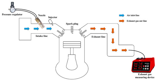
Figure 4.
Schematic of the experimental setup.
Table 5.
Experimental conditions.
4. Results and Discussion
4.1. Simulation Results of the Intake Manifold Using a Nozzle
Figure 5 shows the results of the maximum velocity inside the intake manifold according to the nozzle angle and inlet flow velocity at an engine speed of 2000 rpm. When the nozzle diameter was 5 mm, the maximum velocity inside the intake manifold at a nozzle inlet velocity of 40 km/h at nozzle angles of 30°, 45°, 60°, and 75° was 26.62, 25.66, 25.48, and 25.34 m/s, respectively. At a nozzle inlet speed of 80 km/h, the maximum velocity inside the intake manifold at nozzle angles of 30°, 45°, 60°, and 75° was 29.35, 29.21, 28.67, and 27.9 m/s, respectively. For the inlet velocities of both nozzles, the maximum velocity inside the intake manifold was found at the part where the air at the nozzle outlet and the air inside the intake manifold mix and at a nozzle angle of 30°. When the nozzle diameter was 2.5 mm, the maximum velocity inside the intake manifold at a nozzle inlet velocity of 40 km/h at nozzle angles of 30°, 45°, 60°, and 75° was 26.75, 25.91, 25.81, and 25.37 m/s, respectively. As the nozzle inlet speed increased, the maximum velocity inside the intake manifold at a nozzle inlet speed of 80 km/h at nozzle angles of 30°, 45°, 60°, and 75° was 31.42, 31.34, 31.33, and 31.31 m/s, respectively. Accordingly, overall, the maximum velocity inside the intake manifold with a nozzle of 2.5 mm was higher than the case with a nozzle of 5 mm. Similar to the result of applying a nozzle of 5 mm, the maximum velocity inside the intake manifold was highest at a nozzle angle of 30°. The simulation results confirm that the turbulent kinetic energy increases as the inlet speed of the nozzle increases, and the mixing ratio of the inlet air increases, so the temperature inside the intake manifold decreases. It is confirmed that these effects are greater for a 2.5 mm nozzle diameter because the velocity of the air entering through the nozzle is greater.
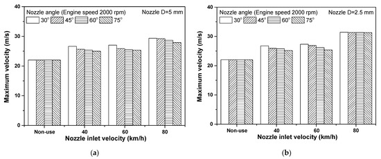
Figure 5.
Maximum velocity in the intake manifold according to nozzle diameter with the nozzle inlet velocity. (a) Nozzle diameter; (b) nozzle diameter of 2.5 mm.
4.2. Experimental Results of Intake Manifold Using a Nozzle
Figure 6 shows the outputs of an automobile engine with a mileage of 30,000 km when a nozzle was used in the intake manifold. When no nozzle was used, the engine output was 93.11 kW, and the engine output at a nozzle inlet speed of 40 km/h when a 5 mm diameter nozzle was used was 93.6 kW. In addition, when the nozzle inlet speeds were 60, 80, and 100 km/h, the engine outputs were measured to be 94.6, 95.0, and 97.5 kW, respectively. When the nozzle inlet speeds were 40 and 100 km/h, the engine outputs were improved by 0.5% and 4.7%, respectively, compared to when no nozzle was used. This is because the air that flowed into the nozzle from the outside formed vortexes inside the intake manifold. The mixing degree and the oxygen density increased to provide a favorable combustion environment. In addition, when a 2.5 mm diameter nozzle was used, the engine outputs at nozzle inlet speeds of 40, 60, 80, and 100 km/h were 96.9, 97.5, 99.0, and 99.9 kW, respectively. The engine output increased by about 4.1%, 4.7%, 6.3%, and 6.7% at each speed compared to when no nozzle was used. The engine outputs of a vehicle with a mileage of 30,000 km increased by 5.4% and 2.2% on average when the nozzle diameters were 2.5 and 5 mm, respectively, and the engine output when the nozzle diameter was 2.5 mm was 3.1% higher on average than that when the nozzle diameter was 5 mm. The smaller the size of the nozzle inlet, the higher the flow rate of the air flowing into the nozzle, which resulted in an increase in the engine output due to the strong vortexes generated inside the intake manifold.
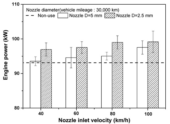
Figure 6.
Comparison of the engine power according to nozzle diameter for the 30,000 km mileage engine.
Figure 7 shows the engine outputs when a nozzle was used in the intake manifold of a vehicle with a mileage of 180,000 km. The output of the old engine for which no nozzle was used was 66.5 kW, a value about 28.5% lower than that of an engine with a mileage of 30,000 km. When a 5 mm diameter nozzle was used, the engine outputs were measured to be 67.0, 67.4, 68.6, and 68.7 kW at nozzle inlet speeds of 40, 60, 80, and 100 km/h, respectively. These values were 0.7%, 1.2%, 3.1%, and 3.3% higher in comparison to engine outputs when no nozzle was used. When a 5 mm diameter nozzle was used, the output of the old automobile engine was improved by about 3.3% in comparison to the case when no nozzle was used. In addition, when a 2.5 mm diameter nozzle was used, the engine outputs were measured to be 67.5, 73.3, 74.4, and 75.4 kW at nozzle inlet speeds of 40, 60, 80, and 100 km/h, respectively, which were improvements of 1.5%, 10.2%, 11.7%, and 13.3%, respectively, in comparison to the case when no nozzle was used. The engine output of the vehicle with a mileage of 180,000 km when a 2.5 mm diameter nozzle was used was 6.9% higher on average than that of the case when a 5 mm diameter nozzle was used. The engine outputs of the vehicles with mileages of 30,000 and 180,000 km at different nozzle inlet speeds increased by 2.2% and 2.1%, respectively, when a 5 mm diameter nozzle was used in comparison to the case when no nozzle was used, and the mileage did not have any significant effect on the degree of improvement in the engine output. On the other hand, when a 2.5 mm diameter nozzle was used, the engine output of the vehicle with a mileage of 180,000 km significantly increased when compared with that of the engine with a mileage of 30,000 km. This is because the nozzle increases the flow speed inside the intake manifold, and the condition approaches perfect combustion as the air density increases due to the inflow of a large amount of outside air. The result of the test showed that, as the effects on these improvements of engine output increased when a nozzle with a smaller diameter of 2.5 mm was used, more significant improvements in the engine output appeared.
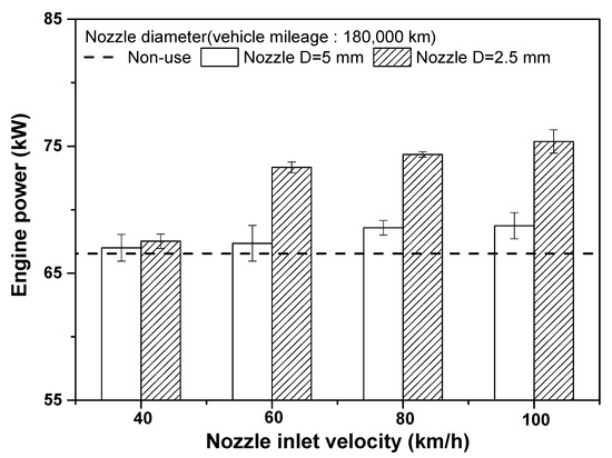
Figure 7.
Comparison of the engine power according to nozzle diameter for the 180,000 km mileage engine.
To determine the effect of using a nozzle in an intake manifold on the exhaust gas under the engine load condition, exhaust gas was measured in the ASM2525 mode, which measures the exhaust gas of gasoline vehicles that do not exceed 5.5 tons. Although in the ASM2525 mode, exhaust gas is measured on a chassis dynamometer at a driving speed of 40 km/h with a road load of 25%, since actual driving conditions include variables other than driving speed, such as wind, in the present study, the components of the emitted exhaust gas were examined with the same nozzle inlet speeds as those of the engine output test by changing the speed from 40 km/h (11.1 m/s) to 60 km/h (16.7 m/s), 80 km/h (22.2 m/s), and 100 km/h (27.8 m/s). Figure 8a shows the changes in HC emissions from the engine with a mileage of 30,000 km at different nozzle inlet speeds in the ASM2525 mode. The HC value of the engine with a mileage of 30,000 km was 0.01483 g/kg when no nozzle was used, and when a 5 mm diameter nozzle was used, the HC value was 0.01459 g/kg at a nozzle inlet speed of 40 km/h, showing a decrease of about 1.6%. In addition, under the same conditions, the HC values decreased to 0.01265, 0.01174, and 0.009 g/kg at nozzle inlet speeds of 60, 80, and 100 km/h, respectively, and when the nozzle inlet speed was 100 km/h, the HC value decreased by 39.3% in comparison to the case when no nozzle was used. In addition, when a 2.5 mm diameter nozzle was used, the HC values showed a decreasing trend to 0.0113, 0.0107, 0.0094, and 0.008 g/kg at nozzle inlet speeds of 40, 60, 80, and 100 km/h, respectively, and when the nozzle inlet speed was 100 km/h, the HC value decreased by 45.8% in comparison to the case when no nozzle was used. The values of HC emitted from the engine with a mileage of 30,000 km decreased by 17.1% on average when a 2.5 mm diameter nozzle was used compared to the case when a 5 mm diameter nozzle was used. Figure 8b shows the changes in HC emissions from the engine with a mileage of 180,000 km at different nozzle inlet speeds in the ASM2525 mode. The HC value of the engine with a mileage of 180,000 km was 0.0218 g/kg when no nozzle was used, and when a 5 mm diameter nozzle was used, the HC values decreased to 0.0198, 0.0176, 0.0164, and 0.01342 g/kg at nozzle inlet speeds of 40, 60, 80, and 100 km/h, respectively. In particular, when the nozzle inlet speed was 100 km/h, HC emissions decreased by 38.4% in comparison to the case when no nozzle was used. In addition, when a 2.5 mm diameter nozzle was used, the HC values were 0.0162, 0.0146, 0.0124, and 0.0108 g/kg at nozzle inlet speeds of 40, 60, 80, and 100 km/h, respectively, and when the nozzle inlet speed was 100 km/h, HC emissions decreased by 50.5% in comparison to the case when no nozzle was used. The result of the test showed that the amount of HC emitted from the engine with a mileage of 180,000 km was 24.8% less than that in the 5 mm case on average. The values of the HC emitted from both engines with mileages of 30,000 and 180,000 km decreased more when the nozzle diameter was 2.5 mm than when it was 5 mm. In addition, when the nozzle diameter was 5 mm, the HC values emitted from engines with mileages of 30,000 and 180,000 km at different nozzle inlet speeds decreased by 39.3% and 38.4%, respectively, showing similar degrees of decrease regardless of the engine mileage. On the other hand, when the diameter of the nozzle was 2.5 mm, the values of the HC emitted from engines with mileages of 30,000 and 180,000 km at different nozzle inlet speeds decreased by 45.8% and 50.5%, respectively, showing a greater decrease in the case of the vehicle with a mileage of 180,000 km. This is because the use of the nozzle brings in more outside air and increases the flow rate of the air flowing in through the nozzle. Such effects were more significant when the diameter of the nozzle was 2.5 mm. These effects improve the combustion performance by providing a uniform combustion environment inside the cylinder through improvements in the turbulent combustion speed and the degree of mixing resulting from the high-speed flow.
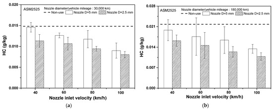
Figure 8.
Variation in HC according to nozzle diameter for 30,000 and 180,000 km mileage engines: (a) 30,000 km engine; (b) 180,000 km engine.
Figure 9a shows the results of measuring the CO gas emitted from the engine with a mileage of 30,000 km at different nozzle inlet speeds in the ASM2525 mode. The CO emission value was 0.046% when no nozzle was used, and when a 5 mm diameter nozzle was used, the CO emission value at a nozzle inlet speed of 40 km/h decreased to 0.043%. The CO emission values were 0.036%, 0.032%, and 0.03% at nozzle inlet speeds of 60, 80, and 100 km/h, respectively, and CO emissions at a nozzle inlet speed of 100 km/h decreased by 34.8% in comparison to the case when no nozzle was used. When a 2.5 mm diameter nozzle was used, the CO emissions were 0.04%, 0.034%, 0.026%, and 0.024% at nozzle inlet speeds of 40, 60, 80, and 100 km/h, respectively, and when the nozzle inlet speed was 100 km/h, the CO emission value decreased by 47.8% in comparison to the case when no nozzle was used. The values of the CO emitted from the engine with a mileage of 30,000 km when the nozzle diameter was 2.5 mm decreased by 12.8% on average in comparison to the case when the diameter of the nozzle was 5 mm. Figure 9b comparatively shows the changes in the CO emitted from the engine with a mileage of 180,000 km at different nozzle inlet speeds in the ASM2525 mode. The CO emission value was 0.17% when no nozzle was used, and when a 5 mm diameter nozzle was used, the CO emission value at a nozzle inlet speed of 40 km/h slightly decreased to 0.167%. The CO emission values were 0.163%, 0.14%, and 0.097% at nozzle inlet speeds of 60, 80, and 100 km/h, respectively, and CO emissions at a nozzle inlet speed of 100 km/h decreased by 42.9% in comparison to the case when no nozzle was used. When a 2.5 mm diameter nozzle was used, the CO emissions were 0.15%, 0.1%, 0.093%, and 0.073% at nozzle inlet speeds of 40, 60, 80, and 100 km/h, respectively, and when the nozzle inlet speed was 100 km/h, the CO emission value decreased by 57.1% in comparison to the case when no nozzle was used. This result is similar to that of the HC test, and the values of the CO emitted from the nozzle with a smaller diameter of 2.5 mm decreased in comparison to the case when the diameter of the nozzle was 5 mm. In addition, when a 5 mm diameter nozzle was used, the values of the CO emitted from the engines with mileages of 30,000 and 180,000 km decreased by 34.8% and 42.9%, respectively, and when the nozzle diameter was 2.5 mm, the decreases were 47.8% and 57.1%, respectively, which shows that the CO reduction effect was greater in the old engine with a mileage of 180,000 km. This is because, similar to the result of the HC test, the airflow speed is higher in the nozzle with a smaller diameter of 2.5 mm, which improves the degree of mixing to form a uniform combustion environment and increase the oxygen concentration, thereby improving the combustion performance.
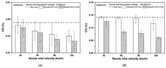
Figure 9.
Variation in CO according to nozzle diameter for 30,000 and 180,000 km mileage engines: (a) 30,000 km engine; (b) 180,000 km engine.
Figure 10a shows changes in the NOx emitted from the engine with a mileage of 30,000 km in accordance with changes in nozzle inlet speeds in the ASM2525 mode. The NOx emission level was 0.0598 g/kg when no nozzle was used, and when a 5 mm diameter nozzle was used, NOx emissions at a nozzle inlet speed of 40 km/h decreased by 13.4% to 0.0518 g/kg. The NOx emission values were 0.0444, 0.0388, and 0.0276 g/kg at nozzle inlet speeds of 60, 80, and 100 km/h, respectively, and NOx emissions at a nozzle inlet speed of 100 km/h decreased by 53.8% in comparison to the case when no nozzle was used. In addition, when a 2.5 mm diameter nozzle was used, the NOx emissions were 0.0478, 0.0334, 0.0242, and 0.0168 g/kg at nozzle inlet speeds of 40, 60, 80, and 100 km/h, respectively, and when the nozzle inlet speed was 100 km/h, the NOx emission value decreased by 71.9% in comparison to the case when no nozzle was used. The results of the test showed that the values of the NOx emitted from the engine with a mileage of 30,000 km when the nozzle diameter was 2.5 mm decreased by 27.7% on average in comparison to the case when the diameter of the nozzle was 5 mm. Figure 10b shows the changes in the NOx emitted from the engine with a mileage of 180,000 km at different nozzle inlet speeds in the ASM2525 mode. The NOx emission value was 0.1477 g/kg when no nozzle was used, and when a 5 mm diameter nozzle was used, the NOx emission value at the nozzle inlet speed of 40 km/h decreased by 0.005 to 0.1403 g/kg. The NOx emissions were 0.13, 0.1193, and 0.1077 g/kg at nozzle inlet speeds of 60, 80, and 100 km/h, respectively, and NOx emissions at the nozzle inlet speed of 100 km/h decreased by 27.1% in comparison to the case when no nozzle was used. In addition, when a 2.5 mm diameter nozzle was used, the NOx emissions were 0.1333, 0.1217, 0.1043, and 0.0927 g/kg at nozzle inlet speeds of 40, 60, 80, and 100 km/h, respectively, and when the nozzle inlet speed was 100 km/h, NOx emissions decreased by 37.2% in comparison to the case when no nozzle was used. In both engines with mileages of 30,000 and 180,000 km, the NOx values when the nozzle diameter was 2.5 mm decreased by 18.4% on average in comparison to the case when the nozzle diameter was 5 mm, which shows that the use of a nozzle with a smaller diameter had the effect of reducing NOx. In addition, when the nozzle diameter was 5 mm, the NOx emitted from the engines with a mileage of 30,000 and 180,000 km at different nozzle inlet speeds decreased by 53.8% and 27.1%, respectively, which shows that the NOx reduction effect was greater in the engine with a mileage of 30,000 km. In addition, when a 2.5 mm diameter nozzle was used, the NOx emitted from the engines with mileages of 30,000 and 180,000 km at different nozzle inlet speeds decreased by 71.9% and 37.2%, respectively, which shows that the NOx reduction effect was greater in the engine with a mileage of 30,000 km. In general, NOx values show an increasing trend when the HC and CO values decrease in an engine depending on the driving condition, and, in the present study, HC, CO, and NOx all showed decreasing trends. This is because the generation of NOx is predominantly affected by the temperature inside the engine, and the use of a nozzle has the effect of reducing the combustion temperature by bringing in low-temperature outside air.
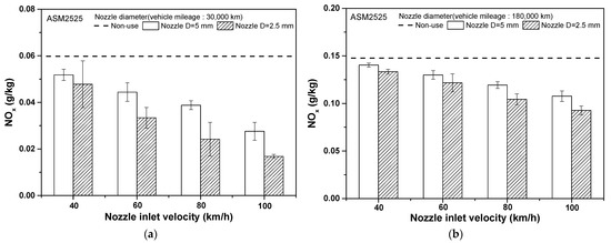
Figure 10.
Variation in NOx according to nozzle diameter for 30,000 and 180,000 km mileage engines: (a) 30,000 km engine; (b) 180,000 km engine.
The present study confirms that the application of a nozzle with a simple structure to introduce external air to the intake manifold improves engine output and effectively reduces exhaust gases (HC, CO, and NOx). In addition, the greater the mileage of the vehicle, the greater the effect. Thus, the use of nozzles in old vehicles can increase engine performance, reduce harmful emissions, and improve vehicle life.
5. Conclusions
In the present study, a nozzle was used to improve the flow performance of an intake manifold, and the effect of the nozzle on the output and exhaust gas of the engine was investigated.
- First, a flow simulation of the intake manifold using the nozzle was performed. Overall, the maximum velocity inside the intake manifold with a nozzle of 2.5 mm was higher than the case with a nozzle of 5 mm. The maximum velocity was highest at a nozzle angle of 30° for both intake manifolds with 2.5 and 5 mm diameter nozzles.
- An engine output performance test was conducted using vehicles with mileages of 30,000 and 180,000 km. When a 5 or 2.5 mm diameter nozzle was used for the vehicle with a mileage of 30,000 km, the engine outputs were improved by 4.7% and 6.5%, respectively, in comparison to the case when no nozzle was used. When a 5 or 2.5 mm diameter nozzle was used in the vehicle with a mileage of 180,000 km, the engine outputs were improved by 3.3% and 13.3%, respectively, compared to the case when no nozzle was used.
- As a result of measuring the exhaust gas emitted from the engine of the vehicle with a mileage of 30,000 km with an intake manifold in which a 5 or 2.5 mm diameter nozzle was installed, hydrocarbon emissions decreased by 39.3% and 45.8%, respectively, in comparison to the case when no nozzle was used, and carbon monoxide emissions decreased by 34.8% and 47.8%, respectively. In addition, when a 5 or 2.5 mm diameter nozzle was used for the vehicle with a mileage of 30,000 km, the nitrogen oxide emission greatly decreased by 53.8% and 71.9% compared to the case when no nozzle was used. When a 5 or 2.5 mm diameter nozzle was used for a vehicle with a mileage of 180,000 km, hydrocarbon emissions decreased by 38.4% and 50.5%, respectively, compared to the case when no nozzle was used, and carbon monoxide emissions decreased by 42.9% and 57.1%, respectively. In addition, nitrogen oxide emissions decreased by 27.1% and 37.2%, respectively.
- It was found that the use of a nozzle for the inflow of outside air improves the combustion speed by forming vortexes inside the intake manifold and, at the same time, forms a uniform combustion environment by increasing the degree of mixing, thereby improving the engine output and dramatically reducing harmful exhaust gases such as hydrocarbon, carbon monoxide, and nitrogen oxides, and the effect is greater for old vehicles in particular.
Author Contributions
Conceptualization, H.C. and T.K.; methodology, J.P. and Y.S.; validation, J.P. and H.C.; formal analysis, Y.S.; investigation, H.C. resources, T.K.; writing—original draft preparation, Y.S. and T.K.; writing—review and editing, H.C. and J.P.; supervision, H.C. All authors have read and agreed to the published version of the manuscript.
Funding
This study was supported by research fund (team research project) from Chosun University, 2020.
Institutional Review Board Statement
Not applicable.
Conflicts of Interest
The authors declare no conflict of interest. The funders had no role in the design of the study; in the collection, analyses, or interpretation of data; in the writing of the manuscript; or in the decision to publish the results.
Abbreviation
| ASM | Acceleration Simulation Mode |
| BTDC | Before top dead center |
| CO | Carbon monoxide |
| CO2 | Carbon dioxide |
| DOHC | Double overhead camshaft |
| GDI | Gasoline direct injection |
| NOx | Nitrogen oxides |
| HC | Hydrocarbon |
References
- Cho, Y.H.; Kim, S.O. EU, EURO 6 Enforcement of Automobile Exhaust Gas Regulation. Compliance in Advance and Supporting System, Korea, BSC Report 359-13-003, 2013; pp.1–6. Available online: http://madams.kr/newsa/130416.pdf (accessed on 14 December 2021).
- Choi, S.B.; Oh, B.Y.; Choi, D.M. Fire Patterns According to the Blood Hb-CO Concentration of Charred Bodies. J. Korean Inst. Fire Sci. Eng. 2012, 26, 40–48. [Google Scholar] [CrossRef]
- Chung, Y.J. Production of Carbon Monoxide and Carbon Dioxide Gases in the Combustion Tests. J. Korean Inst. Fire Sci. Eng. 2015, 29, 7–13. [Google Scholar] [CrossRef][Green Version]
- Mikołaj, M.; Maciej, K.J.; Agnieszka, W.; Olga, C.; Mateusz, K.; Mateusz, B.; Paweł, M.; Katarzyna, T.; Krzysztof, W.; Iwona, G.; et al. Influence of air pollution on exhaled carbon monoxide levels in smokers and non-smokers. A prospective cross-sectional study. Environ. Res. 2017, 152, 496–502. [Google Scholar] [CrossRef]
- Ma, Y.; Liu, A.; Egodawatta, P.; McGree, J.; Goonetilleke, A. Quantitative assessment of human health risk posed by polycyclic aromatic hydrocarbons in urban road dust. Sci. Total Environ. 2017, 575, 895–904. [Google Scholar] [CrossRef] [PubMed]
- Hussein, I.A.; Mona, S.M.M. A review on polycyclic aromatic hydrocarbons: Source, environmental impact, effect on human health and remediation. Egypt. J. Pet. 2016, 25, 107–123. [Google Scholar] [CrossRef]
- Kim, J.S.; Kim, Y.J.; Seo, C.W.; Park, T.W. Analysis of Test Results and Simulation Verification of Intake Manifold. In Proceedings of the Spring Conference of KSAE 2017, Jeju, Korea, 18–20 May 2017; KSAE17-S0091. pp. 199–208. [Google Scholar]
- Park, J.S.; Cho, J.G.; Song, S.H.; Cho, J.Y.; Wang, T.J. Evaluate the Effect of the Intake Manifold Geometry on Cylinder-to-cylinder Variation Using 1D-3D Coupling Analysis. Trans. KSAE 2016, 24, 161–168. [Google Scholar] [CrossRef]
- Kim, Y.B.; Na, C.K.R.; Lee, J.K.; Chu, D.H.; Kim, Y.H. A study on development of plastic intake manifold for gasoline T-GDi engine. In Proceedings of the KSAE Annual Conference 2013, Seoul, Korea, 20–23 November 2013; pp. 154–160. [Google Scholar]
- Kim, B.J.; Kim, S.T.; Ma, J.W.; Na, J.H. Analysis of Characteristics of Distributing Fluid Flow by Geometry of Manifold. In Proceedings of the KSME Fall Conference 2012, Changwon, Korea, 7–9 November 2012; pp. 2881–2882. [Google Scholar]
- Kim, J.S.; Kim, Y.J.; Kim, S.Y.; Park, T.W. A Study on the Loss Factor Characteristics of Intake Manifold Bell Mouse R. In Proceedings of the KSME CAE & Applied Mechanics Division Spring Conference 2017, Busan, Korea, 25–26 May 2017; pp. 355–359. [Google Scholar]
- Beatrice, C.; Belgiorno, G.; Blasio, G.D.; Mancaruso, E.; Sequino, L.; Vaglieco, B.M. Analysis of a Prototype High-Pressure “Hollow Cone Spray” Diesel Injector Performance in Optical and Metal Research Engines 2017-24-0073. In SAE Technical Paper; SAE: Warrendale, PA, USA, 2017. [Google Scholar] [CrossRef]
- Lee, J.W.; Park, T.S. Effect of Exit Shape on Turbulent Outflows in a Distribution Manifold. J. Comput. Fluids Eng. 2014, 19, 73–79. [Google Scholar] [CrossRef]
- Park, J.S.; Lee, K.S.; Song, S.H.; Chun, K.M. Optimization of Diesel Engine Performance with Dual Loop EGR considering Boost Pressure, Back Pressure, Start of Injection and Injection Mass. Trans. KSAE 2010, 18, 136–144. [Google Scholar]
- Zhang, P.; Zhang, J.; Li, Y.; Wu, Y. Nonlinear Active Disturbance Rejection Control of VGT-EGR System in Diesel Engines. Energies 2020, 13, 5331. [Google Scholar] [CrossRef]
- Bondar, V.; Aliukov, S.; Malozemov, A.; Das, A. Mathematical Model of Thermodynamic Processes in the Intake Manifold of a Diesel Engine with Fuel and Water Injection. Energies 2020, 13, 4315. [Google Scholar] [CrossRef]
- Shen, Z.; Cui, W.; Ju, X.; Liu, Z.; Wu, S.; Yang, J. Numeric Investigation of Gas Distribution in the Intake Manifold and Intake Ports of a Multi-Cylinder Diesel Engine Refined for Exhaust Gas Stratification. Energies 2017, 10, 1888. [Google Scholar] [CrossRef]
- Hwang, S.K.; Ko, A.H.; Yoon, J.W.; Myung, C.L.; Park, S.S.; Kim, E. A Study on NOx Reduction Characteristics of LNT Catalyst with Fuel Injection Control in Light-duty Diesel Engine. Trans. KSAE 2012, 20, 150–155. [Google Scholar] [CrossRef]
- Kwon, S.K.; Um, J.S.; Kang, E.J.; Seo, Y.H. Analysis the effects of fuel economy due to the test condition changes in gasoline vehicles. In Proceedings of the KSAE Annual Conference 2015, Gyeongju, Korea, 18–21 November 2015; pp. 203–206. [Google Scholar]
- Lee, S.H.; Lee, C.H.; Lee, J.W.; Lee, S.H.; Min, K.D.; Kim, S.W.; Lee, M.H. The effect of intake air temperature on NOx emissions in light-duty Diesel vehicle and engine. In Proceedings of the KSAE Annual Conference 2013, Seoul, Korea, 20–23 November 2013; pp. 126–128. [Google Scholar]
- Jang, J.H.; Kim, H.J.; Eom, M.D.; Park, S.W.; Chon, M.S. NOx emission characteristics of real driving emissions according to different driving area. In Proceedings of the KSAE Conference and Exhibition 2015, Gyeongju, Korea, 18–21 November 2015; p. 210. [Google Scholar]
- Alasfour, F.N. NOx emission from a spark ignition engine using 30% iso-butanol-gasoline blend: Part 2D-ignition timing. Appl. Therm. Eng. 1998, 18, 245–256. [Google Scholar] [CrossRef]
- Topgül, T.; Yücesu, H.S.; Çinar, C.; Koca, A. The effects of ethanol–unleaded gasoline blends and ignition timing on engine performance and exhaust emissions, Renew. Energy 2006, 31, 2534–2542. [Google Scholar] [CrossRef]
- Zsig, N.; Voser, C.; Onder, C.; Guzzella, L. Intake Manifold Boosting of Turbocharged Spark-Ignited Engines. Energies 2013, 6, 1746–1763. [Google Scholar] [CrossRef]
- Ashrafur Rahman, S.M.; Rizwanul Fattah, I.M.; Ong, H.C.; Zamri, M.F.M.A. State-of-the-Art of Strategies to Reduce Exhaust Emissions from Diesel Engine Vehicles. Energies 2021, 14, 1766. [Google Scholar] [CrossRef]
- Ashrafur Rahman, S.M.; Rizwanul Fattah, I.M.; Ong, H.C.; Ashik, F.R.; Hassan, M.M.; Murshed, M.T.; Imran, M.A.; Rahman, M.H.; Rahman, M.A.; Hasan, M.A.M.; et al. State-of-the-Art of Establishing Test Procedures for Real Driving Gaseous Emissions from Light- and Heavy-Duty Vehicles. Energies 2021, 14, 4195. [Google Scholar] [CrossRef]
- Sayin, C. The impact of varying spark timing at different octane numbers on the performance and emission characteristics in a gasoline engine. Fuel 2012, 97, 856–861. [Google Scholar] [CrossRef]
- Iodice, P.; Senatore, A.; Langella, G.; Amoresano, A. Effect of ethanol–gasoline blends on CO and HC emissions in last generation SI engines within the cold-start transient: An experimental investigation. Appl. Energy 2016, 179, 182–190. [Google Scholar] [CrossRef]
- Dardiotis, C.; Martini, G.; Marotta, A.; Manfredi, U. Low-temperature cold-start gaseous emissions of late technology passenger cars. Appl. Energy 2013, 111, 468–478. [Google Scholar] [CrossRef]
- Moon, S.; Huang, W.; Wang, J. Spray formation mechanism of diverging-tapered-hole GDI injector and its potentials for GDI engine applications. Fuel 2020, 207, 117519. [Google Scholar] [CrossRef]
- Wang, Q.; Xin, B.; Sun, P.; Li, J.; Liu, Q. Nonlinear compensation method for injector in small flow area on GDI engine. IFAC Pap. 2018, 51, 154–157. [Google Scholar] [CrossRef]
- Blasio, G.D.; Vassallo, A.; Pesce, F.C.; Beatrice, C.; Belgiorno, G.; Avolio, G. The Key Role of Advanced, Flexible Fuel Injection Systems to Match the Future CO2 Targets in an Ultra-Light Mid-Size Diesel Engine 2018-37-0005. In SAE Technical Paper; SAE: Warrendale, PA, USA, 2018. [Google Scholar] [CrossRef]
- Miganakallu, N.; Yang, Z.; Rogóż, R.; Kapusta, Ł.J.; Christensen, C.; Barros, S.; Naber, J. Effect of water-methanol blends on engine performance at borderline knock conditions in gasoline direct injection engines. Appl. Energy 2020, 264, 114750. [Google Scholar] [CrossRef]
- Ministry of Environment No. 2013-86. In Regulations on the Test Methods for Driving Vehicle Exhaust Gas Inspection; Ministry of Environment: Sejong, Korea, 5 July 2013.
Publisher’s Note: MDPI stays neutral with regard to jurisdictional claims in published maps and institutional affiliations. |
© 2021 by the authors. Licensee MDPI, Basel, Switzerland. This article is an open access article distributed under the terms and conditions of the Creative Commons Attribution (CC BY) license (https://creativecommons.org/licenses/by/4.0/).