Abstract
An efficient wireless power transfer (WPT) system is proposed using two self-resonant coils with a high-quality factor (Q-factor) over medium distance via an adaptive impedance matching network using ferrite core transformers. An equivalent circuit of the proposed WPT system is presented, and the system is analyzed based on circuit theory. The design and characterization methods for the transformer are also provided. Using the equivalent circuit, the appropriate relation between turn ratio and optimal impedance matching conditions for maximum power transfer efficiency is derived. The optimal impedance matching conditions for maximum power transfer efficiency according to distance are satisfied simply by changing the turn ratio of the transformers. The proposed WPT system maintains effective power transfer efficiency with little Q-factor degradation because of the ferrite core transformer. The proposed system is verified through experiments at 257 kHz. Two WPT systems with coupling efficiencies higher than 50% at 1 m are made. One uses transformers at both Tx and Rx; the other uses a transformer at Tx only while a low-loss coupling coil is applied at Rx. Using the system with transformers at both Tx and Rx, a wireless power transfer of 100 watts (100-watt light bulb) is achieved.
1. Introduction
Wireless power transfer (WPT) using a magnetic field in a near-field region is a topic that has drawn much attention recently. Concurrently, many studies have investigated its various applications, such as in electronic appliances [1,2,3,4], medical devices [5,6,7,8], and electric vehicles [9,10]. In [11], a WPT system that is based on magnetically coupled resonance using transmitting (Tx) and receiving (Rx) self-resonant coils of a high-quality factor (Q-factor) was reported. According to [11], a higher coupling coefficient between the Tx and Rx self-resonant coils and the lower losses in each coil are important for effective mid-range WPT. In addition, satisfying the optimal impedance-matching conditions according to distance is a key factor for attaining maximum power transfer efficiency in the system [11,12,13]. Notably, impedance matching in moving receivers has been found to increase the power transfer efficiency substantially [13].
Few methods for the impedance matching of a WPT system using self-resonant coils of high Q-factor have been reported. In [11], the mutual inductance between the Tx/Rx resonant coils and the non-resonant coupling coils was adjusted by mechanically changing the distance between the Tx/Rx resonant coils and the non-resonant coupling coils. In [14,15], tunable impedance matching methods controlled by an array of lumped elements were presented. Meanwhile, [16] demonstrated real-time impedance matching of a capacitive array using machine learning. However, using lumped elements for impedance matching is not appropriate because the power transfer efficiency can decrease considerably due to series inductors or capacitors of a low Q-factor. In [17], frequency-tracking methods were suggested for adaptive impedance matching. However, a single operating frequency would be better in commercial applications of WPT technology. In addition, as the distance between two resonant coils increases, applying the method becomes difficult.
In this paper, a WPT system that consists of two self-resonant coils of high Q-factors and adaptive impedance-matching networks using ferrite core transformers at Tx and Rx is proposed. Maximum power transfer efficiency can be achieved by applying the adaptive impedance-matching network according to the changing distance between the self-resonant coils or by varying the load impedance. It is true that a transformer is often used as an impedance matcher because of easy implementation, electronic adaptive matching, and wideband behavior. However, few studies have reported on high Q-factor WPT systems using a ferrite core transformer. In [18], the ferrite core transformer was adopted for impedance matching, but it reduced the power transfer efficiency of the system. In the system proposed in this paper, an impedance matching method using ferrite core transformers causes minimal degradation of power transfer efficiency. The characterization and design methods of the ferrite core transformer used in this method are reported herein.
This paper is organized as follows. The circuit analysis performed to obtain power transfer efficiency and optimal impedance matching conditions is explained in Section 2. In Section 3, the characterization and design methods of the ferrite core transformer for the proposed WPT system are explained. In Section 4, the two fabricated WPT systems are presented, and the proposed method and the obtained results are verified through experiments. Section 5 provides the conclusions.
2. WPT System with Ferrite Core Transformers
2.1. Configuration of the Proposed System and Its Analysis
Figure 1a shows a schematic illustration of the proposed WPT system. The primary coil of the Tx transformer is connected to an AC source and its secondary coil is connected to a Tx resonant coil. The primary and secondary coils of the Rx transformer are connected to a load and an Rx resonant coil, respectively. The Tx and Rx resonant coils both have a parallel capacitor (C1 and C2) for adjusting the desired resonant frequency of the proposed WPT system.
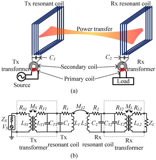
Figure 1.
(a) Illustration of the proposed wireless power transfer (WPT) system and (b) its equivalent circuit.
Figure 1b shows an equivalent circuit of Figure 1a. The parameters in Figure 1b are defined as follows:
- ZS: input port impedance or characteristic impedance of the power source and lossless
- VS: equivalent supply voltage of the power source
- ZL: load impedance and pure resistive
- subscripts S1 and T1: primary and secondary coils of the Tx transformer, respectively
- subscripts L2 and T2: primary and secondary coils of the Rx transformer, respectively
- subscripts 1, 2: Tx and Rx resonant coils, respectively
- LS1 and LT2: self-inductance of the primary coil of the Tx and Rx transformers, respectively
- LT1 and LL2: self-inductance of the secondary coil of the Tx and Rx transformers, respectively
- L1 and L2: self-inductance of the Tx and Rx coils, respectively
- C1 and C2: resonant capacitance of the Tx and Rx coils, respectively
- CT1 and CT2: resonant capacitance of the Tx and Rx transformers, respectively
- C1′ and C2′: sum of the capacitances of the Tx transformer (CT1) and Tx resonant capacitance (C1) and the Rx transformer (CT2) and Rx resonant capacitance (C2), respectively
- RS1 and RT2: sum of ohmic losses, proximity losses, and eddy current losses of the primary coil at the Tx and Rx transformers, respectively
- RT1 and RL2: sum of ohmic losses, proximity losses, and eddy current losses of the secondary coil at the Tx and Rx transformers, respectively
- R1 and R2: ohmic loss of the Tx and Rx coils, respectively
- MS and ML: mutual inductances between the primary and secondary coils of the Tx and Rx transformers
- M12: mutual inductance between the Tx and Rx resonant coils
T-transformation to the Tx and Rx transformers and a coupling unit between the Tx and Rx resonant coils are applied for the analysis of the system, as shown in Figure 1b. Figure 2 shows a modified equivalent circuit of the system shown in Figure 1b.
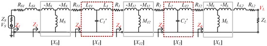
Figure 2.
Modified equivalent circuit obtained by applying T-transformation to each coupling unit.
Z1, Z2, Z3, Z4, Z5, and Z6 are the impedances looking into the load ZL at each coupling unit. XS, X1, X12, X2, and XL denote the transmission (ABCD) matrices of each coupling unit. They are defined as follows [19]:
where L1′ = L1LT1/L1″, L2′ = L2LT2/L2″, L1″ = L1 + LT1, and L2″ = L2 + LT2.
The voltage at load VL is expressed using the transmission matrices (1)–(5) as follows:
where
Here, the self-inductance of the transformer’s secondary coil should be much bigger than that of the primary coil (LT1 >> L1 and LT2 >> L2) to reduce the losses in the secondary coil. Otherwise, the losses will be increased by the current flowing in the transformer’s secondary coil. Therefore, it is important to note that the power transfer efficiency of the proposed system is not degraded because of the transformers since |Z6| >> RT2 and |Z3| >> RT1 compared with the conventional method in which the self-resonant coils are connected to the transformer in series [18].
The resonant frequencies of each self-resonant coil are determined as follows:
The transmission coefficient and the power transfer efficiency are given by
The reflection coefficient is given by
Equation (17) shows that the optimal input impedance matching condition is the conjugate of the input impedance of the system Z1* = ZS and that there is no reflection loss. The optimal input impedance-matching condition can be achieved using the Tx transformer.
2.2. Optimal Impedance Matching
In a conventional WPT system that has two self-resonant coils, the optimal load impedance for maximum power transfer efficiency is as follows [11]:
where U12 is the figure of merit for the resonant wireless power transfer system, which can be used for the maximum achievable efficiency between the two resonant coils as explained in [20]. The condition can also be applied to the proposed WPT system. Therefore, Z5 must be satisfied with the Zopt of (17) for maximum power transfer efficiency.
To calculate the optimal impedance matching condition in the proposed WPT system, it is assumed that |Z6| >> RT2 and Im(Z5) ≈ 0 (See Appendix A for validation of assumption). The two assumptions are verified in Section 4. Under this assumption, Z5 in (8) is rewritten as (18) from (9) and (12) when ω2 = 1/L2′C2′.
By using the assumption Im(Z5) ≈ 0, the magnitude of Z5 is given by
where ZL′ = RL2 + ZL. kL denotes the coupling coefficient of the Rx transformer. For optimal load impedance matching, |Z5| = Zopt in (17), which can be the second order equation of LL2. Therefore, the optimal self-inductance of the Rx transformer’s primary coil (LL2) is obtained by solving the second order equation of LL2 as follows:
Therefore, the optimal number of turns of the Rx transformer’s primary coil Nopt is determined for the optimal load impedance matching condition as follows:
where A0 is the self-inductance per turn of the Rx transformer. This is explained in detail in the following section. If the system is symmetric, the optimal input impedance matching condition is the same as the load impedance matching condition. That is, Np1opt = Np2opt. Otherwise, the optimal input impedance matching condition can be obtained from (16).
3. Transformers Characteristic Method
Figure 3 shows the schematic illustration of a toroidal ferrite core for a transformer that is used in the WPT system. The parameter S indicates the cross-sectional area of the core (S = W × h), where W and h denote the width and the height, respectively. The inner radius of the core (rin) depends on the maximum magnetic flux density of the system.
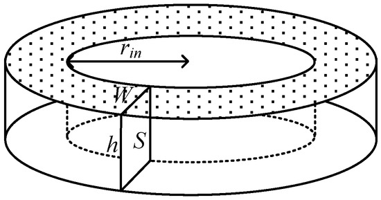
Figure 3.
Schematic illustration of a toroidal core for a transformer.
The self-inductance per turn A0 can be derived by referring to Figure 3 and expressed by (22) and the self-inductance with N-turn, L, is expressed by (23).
Here, l1 turn denotes the coil length per turn and is obtained as summing 2 × (W + h) and 4 times of wire diameter, while µ0 and µr represent the permeability in the vacuum and the relative permeability of the ferrite core, respectively [21].
Figure 4 shows an equivalent circuit of a practical transformer [21]. The inter-winding capacitance between the transformer’s primary and secondary coils and the self-capacitance of the primary coil are negligible because of the very low capacitance. Ll1 (= (1 − k)LS) and Ll2 (= (1 − k)LT) denote the leakage inductance of the primary and secondary coils, respectively; Lp (= kLS) denotes the magnetizing inductance of the primary coil; and NS and NT are the number of turns of the primary and secondary coils, respectively. Thus, the self-inductances of the transformer’s primary and secondary coils are LS = Ll1 + Lp and LT = Ll2 + Lp(NT/NS), respectively. CT is the self-capacitance of the secondary coil, and RS and RT represent the resistance of the primary and secondary coils, respectively.
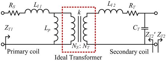
Figure 4.
Equivalent circuit of a practical transformer.
In the design step, A0 can roughly evaluate the transformer. However, for a more accurate circuit analysis of the WPT system using self-resonant coils of high Q-factor, the detailed electric parameters of a real transformer, such as parasitic capacitance, coupling coefficients, and self-inductance, are necessary.
The self-inductances and the coupling coefficients are obtained with open and short circuit measurements, where the self-inductances are measured at the primary side (Im(ZT1)) when the secondary coil remains open (ZT2 = ∞) and short (ZT2 = 0), respectively. The self-inductance of the primary coil LS is easily achieved from the open circuit test as follows:
The coupling coefficients of kS and kL of the Tx and Rx transformers, and , can be found with the open and short circuit tests, respectively. The result of the short circuit test is given by:
Here, n = NT/NS, that is, the turn ratio of the primary and secondary coils. It is assumed that ωLl2 is much bigger than RT, which is reasonable because the transformer’s secondary coils have high leakage inductance caused by their numerous windings (See Appendix A for validation of assumption). Therefore, the coupling coefficients are obtained as follows:
The input impedance looking into the primary coil at the secondary coil (ZT2′) is measured to achieve the self-inductance (LT), self-capacitance (CT), and resistance (RT) of the transformer’s secondary coil. Since it seems that direct measurement of CT using an LCR meter or a vector network analyzer is difficult, more accurate values can be extracted by measuring the self-resonant frequency (ωT) of the secondary coil. After ωT is measured, the resistance (RT) and self-inductance (LT) can be achieved by measuring the input impedance at the operating frequency, as shown in (27) and (28). Since the value of (1 − ω2LTCT) is generally much greater than that of ωRTCT, (27) and (28) can be simplified as a function of ω, ωT, and RT or LT, respectively.
ω and ωT are known, so the resistance and the self-inductance of the transformer’s secondary coil are achieved as (29) and (30), respectively.
Next, the self-capacitance can be calculated using the ωT and LT of the secondary coil.
4. Experimental Results and Verification
4.1. WPT System Using Both Tx and Rx Transformers
4.1.1. Fabrication and Measurement of Parameters
Figure 5 shows a photograph of the fabricated WPT system. Two identical rectangular and helical resonant coils (62 cm × 33 cm × 4 cm) are fabricated using 14 AWG litz wire for the Tx and Rx resonant coils. The resonant coils have 19 turns. The toroidal cores for the transformers consist of two semicircular Ni-Zn ferrite cores (µr = 350, SN-03BH) [22]. The dimensions of the core are W = 1.2 cm, h = 3.7 cm, and rin = 2.7 cm. To obtain the proper A0, the air gap of each ferrite core is tuned using insulating tape. The measured A0 of the fabricated Tx and Rx transformers are 0.56 µH/turn2 and 0.53 µH/turn2, respectively. To adjust the resonant frequencies of each self-resonant coil, a high-Q lumped capacitor of 1 nF is connected to both Tx and Rx resonant coils in parallel. The secondary coils of the Tx and Rx transformers have 91 and 94 turns, respectively.
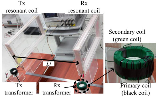
Figure 5.
Photograph of the fabricated WPT system using both Tx and Rx transformers.
Table 1 shows the measured electric parameters of the fabricated WPT system. Each electric parameter of the transformers is obtained by substituting the measured values from the vector network analyzer (Agilent 4395A) and the LCR meter (GWINstek LCR8110G) in (24)–(31). As shown in Table 1, the electric parameters of the Tx and Rx transformers are slightly different, whereas the resonant frequencies of the Tx and Rx resonant coils are almost the same. The resonant frequencies are measured with the transformer connected to the resonant coil because the resonant frequency is affected by the transformer’s secondary coil. The Q-factors of the Tx and Rx resonant coils without the transformer are 549 and 525, respectively.

Table 1.
Measured parameters of the fabricated wireless power transfer (WPT) system.
Figure 6 shows the coupling coefficients and self-inductances of the Tx and Rx transformers’ primary coils according to the number of turns. Their coupling coefficients are approximately 0.9. In addition, the coupling coefficients of the fabricated transformers remain almost constant even if the number of turns of the primary coils is changed. The primary coils’ self-inductances increase from 2.5 µH to 25 µH according to the number of turns. The self-inductance of the Tx transformer’s primary coil is slightly higher than that of the Rx transformer because of the difference in A0.
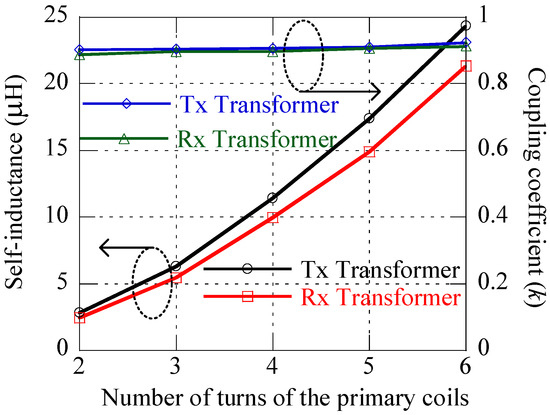
Figure 6.
Coupling coefficients and self-inductances of the primary coils depending on the number of turns.
4.1.2. Mutual Inductance and Optimal Impedance Matching
Figure 7 shows the measured mutual inductance and the number of turns of the transformers’ primary coils for optimal impedance matching conditions according to the center-to-center distance (D) between two self-resonant coils. The circle-marked solid line represents the measured mutual inductance M12 when D is varied from 40 cm to 100 cm. M12 = 20.8 µH at 40 cm, whereas M12 = 3.1 µH at 100 cm. The square-marked dotted line denotes the calculated optimal number of turns for the Tx transformer (Np1opt), while the rhombus-marked dotted line denotes the optimal number of turns for the Rx transformer (Np2opt). ZS = ZL = 50 Ω is assumed for the calculation. For comparison with the calculations, the measured optimal number of turns (Npopt) is also represented by filled triangles. The measured Npopt is achieved by measuring the maximum S21 of the system according to the distance.
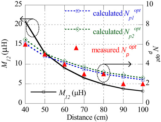
Figure 7.
Measured mutual inductance and calculated and measured numbers of turns in the primary coils of the Tx and Rx transformers for optimal impedance matching condition according to the distance.
The fabricated system is symmetric, so Np1opt = Np2opt = Npopt. However, Np1opt and Np2opt will be different if the Tx and Rx resonant coils are different. It is observed that Npopt is a positive integer that decreases from 6 to 2 as the distance increases. The measured results are in good agreement with the calculated ones. Moreover, the results show that the optimal impedance matching condition is easily achieved by changing the number of turns in each primary coil according to the distance between the Tx and Rx resonant coils.
Figure 8 shows the real and imaginary calculated and measured input impedance (Z1) according to the distance, respectively. For the calculation and the measurement, the optimal impedance matching condition shown in Figure 7 is used, and the resonant frequency is 257 kHz. The black solid line represents 50 Ω in reference to the port impedance. The square-marked and triangle-marked solid lines are the real and imaginary calculated input impedances, while the filled squares and filled triangles are those of the measured input impedances, respectively. The imaginary value of the input impedance is close to zero, while the real one varies from 30 Ω to 70 Ω. Notably, the measurement coincides well with the calculation.
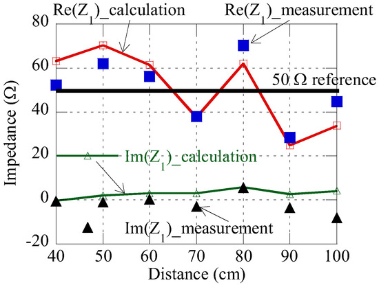
Figure 8.
Comparison between calculated and measured input impedance (Z1) of the fabricated system.
4.1.3. Power Transfer Efficiency
Figure 9 shows the measured and calculated power transfer efficiencies. The square-marked dotted line and the filled square indicate the calculated and measured power transfer efficiencies, respectively, when the input and load impedances are simultaneously matched. The rhombus-marked solid line represents the theoretical maximum power transfer efficiency (ηmax = U122/(1 + (1 + U122)0.5)2) in [11]. The measured parameters of the fabricated WPT system and (15) are used for the calculation of power transfer efficiency. The triangle-marked dotted line represents the efficiency for the case in which the Tx and Rx impedance matching condition is fixed with the optimal impedance matching condition at D = 60 cm (Np1opt = N p2opt = 4).
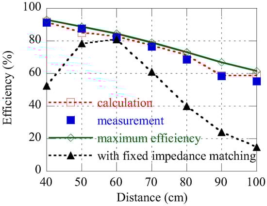
Figure 9.
Measured and calculated power transfer efficiencies with optimal impedance matching, theoretical maximum power transfer efficiency (ηmax), and measured power transfer efficiency with the impedance matching condition fixed at D = 60 cm (Np1opt = Np2opt = 4).
The results show that the calculated and measured power transfer efficiencies are in good agreement. The measured power transfer efficiency is also consistent with the theoretical maximum power transfer efficiency, although the measured one at D = 90 cm is slightly lower (7.4%) because of the minor error of impedance mismatch at the ports. It is also observed that when the impedance matching condition is fixed at D = 60 cm, the power transfer efficiency reaches the maximum value at 60 cm and rapidly decreases according to the distance. The results verify that the proposed WPT system can effectively transfer power over a medium-range between two self-resonant coils with the aid of the proposed adaptive impedance matching method using ferrite core transformers.
Figure 10 shows a WPT experiment for a 100-watt light bulb using the proposed WPT system. The bulb is lit using the two transformers at both Tx and Rx at a 60-cm distance.
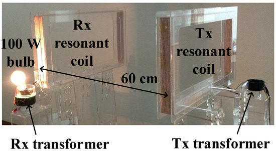
Figure 10.
Photograph of a 100-watt light bulb.
4.2. WPT System Using a Tx Transformer Only
In order to present the various applications of the proposed WPT system, a WPT system with a Tx transformer for a Tx part and a load coil for an Rx part is also fabricated.
Figure 11 shows a schematic illustration of an Rx part with an Rx resonant coil and a load coil. The load coil is a planar rectangular coil. WL is the width, HL is the length, pL is the pitch, NL is the number of turns of the load coil, and D2L is the distance between the Rx resonant coil and the load coil, respectively. The mutual inductance (M2L) between the Rx resonant coil and the load coil should be calculated for optimal impedance matching using the load coil. As in [23], the optimal design of the load coil is made to satisfy the optimal impedance matching condition in (17).
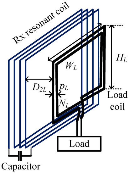
Figure 11.
Schematic illustration of an Rx part using a load coil.
Table 2 shows the calculated design parameters of the rectangular load coil for optimal load impedance matching. In the calculation, the Rx resonant coil is the same as that shown in Figure 5. M2Lopt denotes the optimal mutual inductance between the two coils that is required to satisfy the optimal impedance matching condition according to D. M2Lopt can be easily obtained by varying the dimensions of the load coil. It is assumed that WL = 62 cm, D2L = 5 mm, and pL = 2.5 mm. The Rx resonant coil and the load coil are arranged coaxially to each other. As the distance increases from 40 cm to 100 cm, the geometric dimensions of the load coil can be adjusted for optimal impedance matching. In this case, the number of turns for input impedance matching is the same as that shown in Figure 7. Table 2 shows that the dimension of the load coil should be changed continuously according to the distance.
Table 2.
Design parameters of the rectangular load coil for optimal load impedance matching in Figure 11.
Table 3 shows the optimal number of turns of the Tx transformer’s primary coil when the load coil is fixed at WL = 62 cm, HL = 33 cm, and NL = 1. For optimal input impedance matching, the primary turns change from 9 to 2 according to the distance, which is different from that shown in Figure 7.
Table 3.
Optimal number of turns of the Tx transformer’s primary coil when the load coil is fixed (Case 3 in Figure 12).
Figure 12 shows the three measured power transfer efficiencies. In case 1, both Tx and Rx transformers are used, as shown in Figure 5. In case 2, a Tx transformer and a load coil are used, as shown in Figure 11. In case 3, the Tx transformer is used while the load coil is fixed for impedance matching at D = 60 cm (WL = 62 cm, HL = 33 cm, NL = 1). Figure 12 illustrates that case 2 is highly consistent with case 1. It should be noted that because the total inductance is changed, in cases 2 and 3, a high-Q capacitor of 932 pF is connected to the Rx resonant coil instead of the capacitor of 1 nF shown in Table 1 in order to adjust the resonant frequency. The result of case 3 shows that maximum power transfer efficiency is almost obtained from 40 cm to 70 cm, whereas power transfer efficiency from 70 cm to 100 cm decreases to the maximum point of 20% compared to cases 1 and 2. However, it should be noted that in case 3, a proper impedance matching condition fixed at the Rx part can be well applied within a limited operating range(40 cm to 70 cm), such as in mobile device charging, because the Rx part can be compact and built-in in these devices.
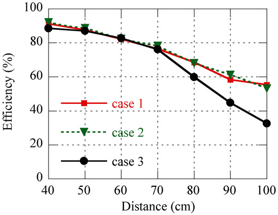
Figure 12.
Measured power transfer efficiencies among three impedance matching cases (case 1: with transformers in both sides; case 2: with the combined impedance matching method; case 3: with load impedance matching fixed in case 2).
The results underscore that the proposed system is capable of efficiently transferring power over a medium range. Furthermore, the system can be well applied to various applications, such as mobile devices and electric vehicles.
This work is compared with the previous works in Table 4. Normalized operation range is the operation range normalized by the maximum length of the Tx coil in each paper. For the case of a circular loop Tx coil, the maximum length is the diameter of the coil, and for a rectangular coil, the maximum length is diagonal of the coil. PTE stands for power transfer efficiency. As shown in Table 1, the proposed method can be better for medium power wireless power transfer over mid-range distance, while for the case using tunable capacitors, high Q capacitors such as vacuum capacitors can be used as explained in [14].
Table 4.
Comparison between previous works and this work.
5. Conclusions
An effective WPT system with practical and useful adaptive impedance matching using ferrite core transformers is built. The equivalent circuit is provided, and power transfer efficiency and optimal impedance matching conditions at Rx and Tx are obtained. The detailed design procedures of the system and the ferrite core transformer are presented. The wireless power transfer of a 100-watt light bulb at 60 cm is also demonstrated. Furthermore, for various applications, two modified WPT systems are presented based on adaptive impedance matching by using the transformer at Tx only. The measurement results show that the system can transfer power over a mid-range, and the power transfer efficiency is as good as the theoretical maximum power transfer efficiency. In addition, the proposed system can support adaptive impedance matching electronically (not mechanically) depending on the application. Therefore, the system can be effectively applied for the wireless charging of moving targets, such as robots, electric vehicles, or mobile devices over a mid-range.
Author Contributions
Conceptualization, J.K. (Jinwook Kim) and Y.-J.P.; methodology, J.K. (Jinwook Kim) and D.-H.K.; validation, J.K. (Jinwook Kim), D.-H.K. and Y.-J.P.; formal analysis, J.K. (Jinwook Kim); investigation, J.K. (Jinwook Kim); resources, Y.-J.P.; data curation, J.K. (Jinwook Kim) and J.K. (Jieun Kim); writing—original draft preparation, J.K. (Jinwook Kim) and Y.-J.P.; writing—review and editing, Y.-J.P., D.-H.K. and J.K. (Jieun Kim); visualization, J.K. (Jieun Kim); supervision, Y.-J.P.; project administration, Y.-J.P.; funding acquisition, Y.-J.P. All authors have read and agreed to the published version of the manuscript.
Funding
This research was funded by the KERI Primary research program of MSIT/NST, grant number 21A01033 and the Industrial Infrastructure Program for Fundamental Technologies of KIAT, grant number P0014854 (21A02059), and the Ministry of Trade, Industry and Energy (MOTIE), Korea.
Institutional Review Board Statement
Not applicable.
Informed Consent Statement
Not applicable.
Data Availability Statement
Data available on request due to restrictions eg privacy or ethical.
Conflicts of Interest
The authors declare no conflict of interest.
Appendix A. Validation of some assumptions of |Z6| >> RT2, |Z3| >> RT1, Re(Z5) ≈ 0, and ωLl2 >> RT.
In Section 2, three assumptions of |Z6| >> RT2, |Z3| >> RT1, and Im(Z5) ≈ 0 are used to derive the optimal impedance matching condition. To validate the assumptions, the measured values of the fabricated WPT system shown in Table 1 are substituted into the equivalent circuit of Figure 2. |Z3| is 20 to 122 times bigger than RT1 and |Z6| is 15 to 100 times bigger than RT2, according to the measured parameters.
Z5 can be obtained by substituting the measured parameters and the optimal impedance matching condition into Figure 2. Figure A1 shows the comparison of Zopt and Z5 according to the distance. The rectangle-marked solid line represents Zopt, whereas the rectangles and triangles indicate Re(Z5) and Im(Z5), respectively. The result shows that Im(Z5) ≈ 0 is almost zero. Furthermore, it can be noted that Re(Z5) is in good agreement with the calculated Zopt.
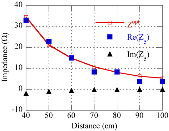
Figure A1.
Comparison of Z2opt and Z5 according to the distance.
In Section 3, it is assumed that ωLl2 >> RT. Since the impedance of the leakage inductance ωLl2 = ωLT2(1 − k) in the Rx transformer ωLl2 is at least 25 times bigger than the RT2 shown in Table 1 and Figure 6, the assumption that ωLl2 >> RT is reasonable. The resistances of the transformers’ primary coil are measured from 0.05 Ω to 0.2 Ω depending on the number of turns. Hence, RS1 and RL2 in Figure 2 can be negligible compared to the input and load impedances, respectively.
References
- Feng, J.; Li, Q.; Lee, F.C.; Fu, M. Transmitter coils design for free-positioning omnidirectional wireless power transfer system. IEEE Trans. Ind. Inform. 2019, 15, 4656–4664. [Google Scholar] [CrossRef]
- Kim, D.-H.; Kim, S.; Kim, S.-W.; Moon, J.; Cho, I.; Ahn, D. Coupling extraction and maximum efficiency tracking for multiple concurrent transmitters in dynamic wireless charging. IEEE Trans. Power Electron. 2020, 35, 7853–7862. [Google Scholar] [CrossRef]
- Li, Z.; Song, K.; Jiang, J.; Zhu, C. Constant current charging and maximum efficiency tracking control scheme for supercapacitor wireless charging. IEEE Trans. Power Electron. 2018, 33, 9088–9100. [Google Scholar] [CrossRef]
- Huang, M.; Lu, Y.; Martins, R.P. A reconfigurable bidirectional wireless power transceiver for battery to battery wireless charging. IEEE Trans. Power Electron. 2019, 34, 7745–7753. [Google Scholar] [CrossRef]
- Lee, B.; Ahn, D.; Ghovanloo, M. Three-phase time-multiplexed planar power transmission to distributed implants. IEEE J. Emerg. Sel. Topics Power Electron. 2016, 4, 263–272. [Google Scholar] [CrossRef] [PubMed] [Green Version]
- Basar, M.R.; Ahmad, M.Y.; Cho, J.; Ibrahim, F. An improved wearable resonant wireless power transfer system for biomedical capsule endoscope. IEEE Trans. Ind. Electron. 2018, 65, 7772–7781. [Google Scholar] [CrossRef]
- Zhou, Y.; Liu, C.; Huang, Y. Wireless power transfer for implanted medical application: A review. Energies 2020, 13, 2837. [Google Scholar] [CrossRef]
- Liu, C.; Jiang, C.; Song, J.; Chau, K.T. An effective sandwiched wireless power transfer system for charging implantable cardiac pacemaker. IEEE Trans. Ind. Electron. 2019, 66, 4108–4117. [Google Scholar] [CrossRef]
- Zhou, S.; Mi, C.C. Multi-paralleled LCC reactive power compensation networks and their tuning method for electric vehicle dynamic wireless charging. IEEE Trans. Ind. Electron. 2016, 63, 6546–6556. [Google Scholar] [CrossRef]
- Mou, X.; Groling, O.; Sun, H. Energy-efficient and adaptive design for wireless power transfer in electric vehicles. IEEE Trans. Ind. Electron. 2017, 64, 7250–7260. [Google Scholar] [CrossRef] [Green Version]
- Kurs, A.; Karalis, A.; Moffatt, R.; Joannopoulos, J.D.; Fisher, P.; Soljacic, M. Wireless power transfer via strongly coupled magnetic resonances. Science 2007, 317, 83–86. [Google Scholar] [CrossRef] [PubMed] [Green Version]
- Kim, D.-H.; Ahn, D. Maximum efficiency point tracking for multiple-transmitter wireless power transfer. IEEE Trans. Power Electron. 2020, 35, 11391–11400. [Google Scholar] [CrossRef]
- Zhong, W.; Hui, S.Y.R. Maximum energy efficiency operation of series-series resonant wireless power transfer system using on-off keying modulation. IEEE Trans. Power Electron. 2018, 33, 3595–3603. [Google Scholar] [CrossRef]
- Beh, T.C.; Kato, M.; Imura, T.; Oh, S.; Hori, Y. Automated impedance matching system for robust wireless power transfer via magnetic resonance coupling. IEEE Trans. Ind. Electron. 2013, 60, 3689–3698. [Google Scholar] [CrossRef]
- Kim, J.; Jeong, J. Range-adaptive wireless power transfer using multiloop and tunable matching techniques. IEEE Trans. Ind. Electron. 2015, 62, 6233–6241. [Google Scholar] [CrossRef]
- Jeong, S.; Lin, T.; Tentzeris, M. A real-time impedance matching utilizing a machine learning strategy based on neural networks for wireless power transfer systems. IEEE Trans. Microw. Theory Tech. 2019, 67, 5340–5347. [Google Scholar] [CrossRef]
- Sample, A.P.; Meyer, D.A.; Smith, J.R. Analysis, experimental results, and range adaptation of magnetically coupled resonators for wireless power transfer. IEEE Trans. Ind. Electron. 2011, 58, 544–554. [Google Scholar] [CrossRef]
- Kim, H.S.; Won, D.H.; Jang, B.J. Simple design method of wireless power transfer system using 13.56 MHz loop antennas. In Proceedings of the IEEE International Symposium on Industrial Electronics, Bari, Italy, 4–7 July 2010; pp. 1058–1063. [Google Scholar]
- Pozar, D.M. Microwave Engineering, 3rd ed.; John Wiley & Sons, Inc.: New York, NY, USA, 2005; pp. 183–186. [Google Scholar]
- Stein, A.L.F.; Kyaw, P.A.; Sullivan, C.R. Figure of merit for resonant wireless power transfer. In Proceedings of the 2017 IEEE 18th workshop on Control and Modeling for Power Electronics (COMPEL), Stanford, CA, USA, 9–12 July 2017; pp. 1–7. [Google Scholar]
- Dai, N.; Lee, F.C. Characterization and analysis of parasitic parameters and their effects in power electronics circuit. Proc. Power Electron. Spec. Conf. 1996, 2, 1370–1375. [Google Scholar]
- Samwha Electronics. Available online: http://www.samwha.co.kr/ (accessed on 1 December 2021).
- Kim, J.; Son, H.-C.; Kim, D.-H.; Kim, K.-H.; Park, Y.-J. Efficiency of magnetic resonance WPT with two off-axis self-resonators. In Proceedings of the IEEE MTT-S International Microwave Workshop Series on Innovative Wireless Power Transmission: Technologies, Systems, and Applications (IMWS-IWPT 2011), Kyoto, Japan, 12–13 May 2011; pp. 127–130. [Google Scholar]
Publisher’s Note: MDPI stays neutral with regard to jurisdictional claims in published maps and institutional affiliations. |
© 2021 by the authors. Licensee MDPI, Basel, Switzerland. This article is an open access article distributed under the terms and conditions of the Creative Commons Attribution (CC BY) license (https://creativecommons.org/licenses/by/4.0/).