1. Introduction
With the recent development of communication technology, the internet of things (IoT) devices have been rapidly evolving. For many IoT devices, the cost of wiring and replacement of the battery is enormous if wire or battery power is used to supply electricity [
1,
2]. To solve this problem, wireless power transfer (WPT) has been an alternative in IoT devices. WPT includes some methods, such as electromagnetic induction, electric field coupling, magnetic field resonance, and microwave power transmission (MPT). Among these methods, MPT has the advantages that it can be used over long distances and that electrical direction control by a phased array antenna is possible. However, MPT has the disadvantages of lower efficiency compared with other methods, and the strength is limited for safety to the human body [
3]. To transmit microwaves with high efficiency and safety, it is necessary to make the power beam accurately track the receiver, and a method called retrodirective is often used to facilitate the tracking of the receiver [
1,
2,
4,
5,
6,
7,
8,
9,
10,
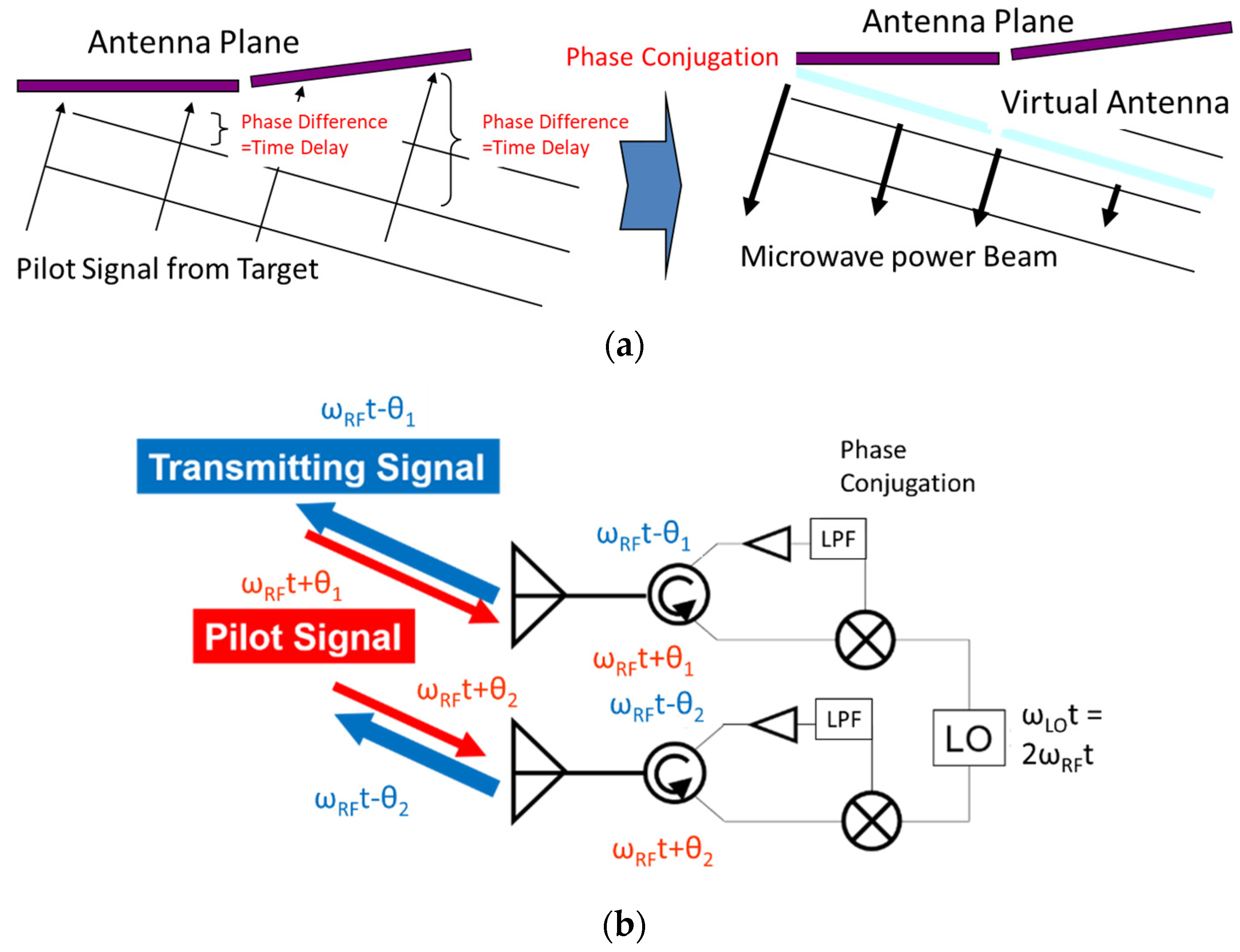
11]. Retrodirective is a target-tracking method that sends back the power transmission signal in the same direction as the pilot signal transmitted from the power receiving device. In this research, retrodirective is achieved by amplifying and transmitting the phase-conjugate signal of the pilot signal, and we assumed a technique called hardware retrodirective (
Figure 1a).
The retrodirective is basically same as a corner reflector and originally Van-Atta array [
12]. In the corner reflector, incoming signals are reflected back in the direction of arrival through multiple reflections. The Van Atta array consists of pairs of antennas equidistantly spaced from the center of the array and connected with the same length transmission lines. The signal received by an antenna is re-radiated by its pair; thus, the order of re-radiating elements is inverted with respect to the center of the array, achieving proper phasing for retrodirectivity. The retrodirective system consists of an array antenna with phased conjugation circuits and it sends back the phase-conjugate signal toward the pilot signal transmitted from the receiver (
Figure 1b), which play the same role as the corner reflector and the Van Atta Array. A pilot signal transmitted from the target (amplitude:
, angular frequency:
, and phase at each antenna:
) is received and re-radiated through the phase-conjugate circuit in the direction of the target. A local signal (amplitude:
and angular frequency:
) is used for phase conjugation. Two forms of the pilot signal and the local signal are mixed, and the conjugate signal
is obtained as defined by the following equation. In the paper, we apply the same retrodirective algorism and hardware for the multipath retrodirective.
When a low-pass filter is used after mixing, the following signal is obtained. The phase
is changed to
If we choose
, Equation (2) becomes
Conventional retrodirective assumed beamforming for only line-of-sight (a direct wave) in an environment without multipath. However, in multipath environments, a signal from a single wave source arrives at a receiver from multiple directions, and the phase and intensity fluctuate because of mutual interference [
13,
14]. Research on retrodirective MPT at sea level for offshore power plants has reported that in a multipath environment, the phase-conjugate signal can be reproduced, including the effect of the multipath of the pilot signal [
9]. Then, we call it multipath retrodirective [
10,
11]. Ossia Inc. proposed a technology called Cota, which uses a method similar to multipath retrodirective to transmit microwaves [
15]. They transmit the phase-conjugate transmission signal back to the multipath pilot signal so that the transmission signal reproduces the multipath of the pilot signal in the opposite direction and concentrates on the power receiving device. It has been reported that power can be synthesized from direct waves and from multipath so that the efficiency is improved compared with the power transmission by only one path. However, a more detailed study has been required on what kind of transmission signal intensity distribution is generated in space by the multipath retrodirective. This research aims at the development of an MPT system that realizes a safe and efficient operation in multipath environments. Furthermore, as a new application of retrodirective, we propose retrodirective using the amplitude information as well as the phase information of the pilot signal, and we propose retrodirective for multiple targets.
2. Multipath Retrodirective
Here, we discuss the electric field distribution of the transmitted signal in a multipath environment and the received power at the receiving antenna. We conducted electromagnetic field simulations in COMPUTER SIMULATION TECHNOLOGY MICROWAVE STUDIO (3D-FIT) (DassaultSystèmesSimuliaCorp, Providence, US) [
11].
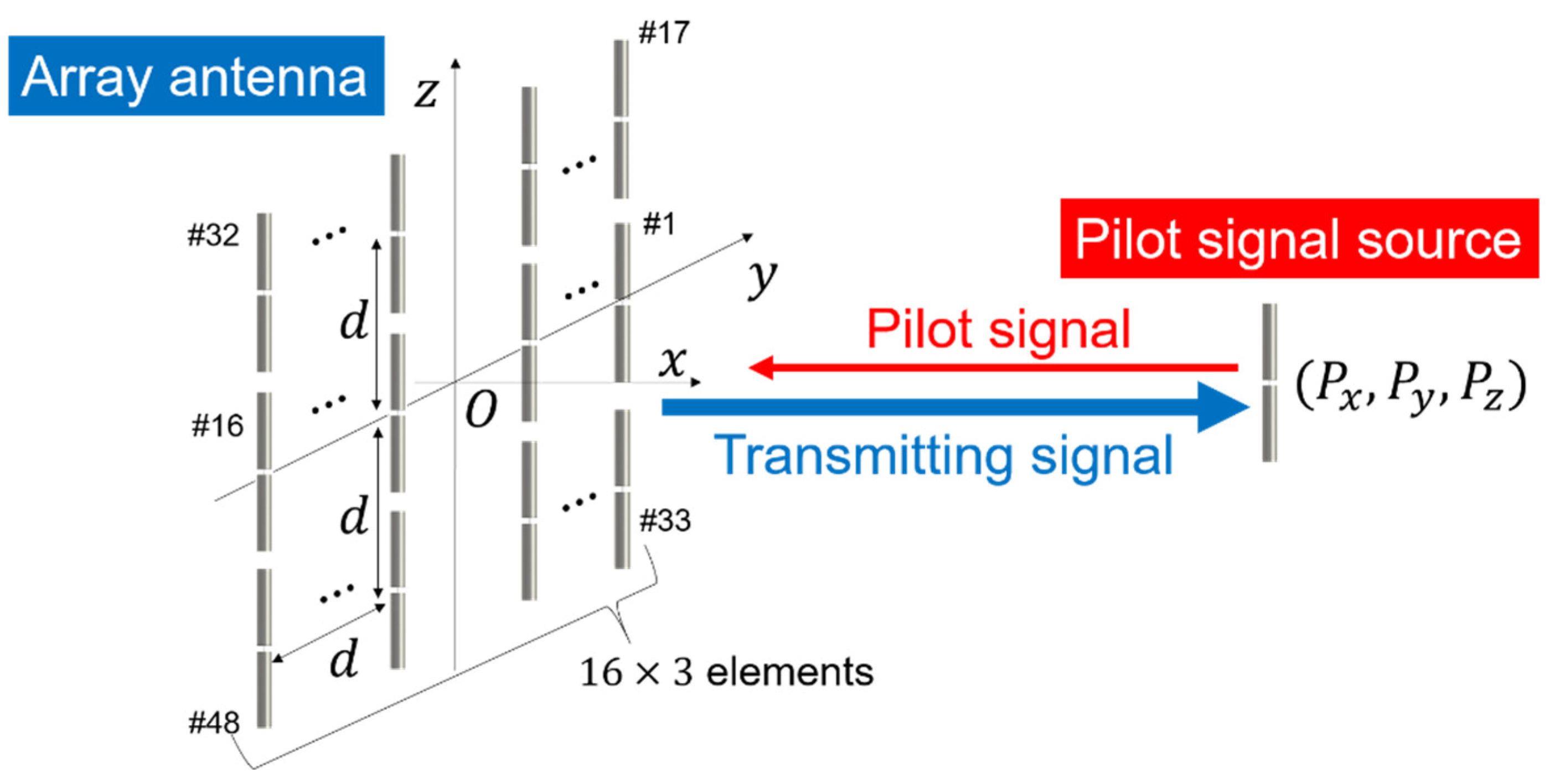
Figure 2 shows the layout of the system. All elements are half-wave dipoles, with the center of the array at the origin (0 m, 0 m, 0 m). The pilot signal source (or receiving antenna) is set at (Px, Py, Pz) = (3 m, 0 m, 0 m). The array consists of 16 × 3 elements, and each element spacing was 0.6 λ. The frequency of each signal was 2.45 GHz, and the input power to each port was uniformly 0.5 W (the input power to the 16 × 3 element array was 24 W).
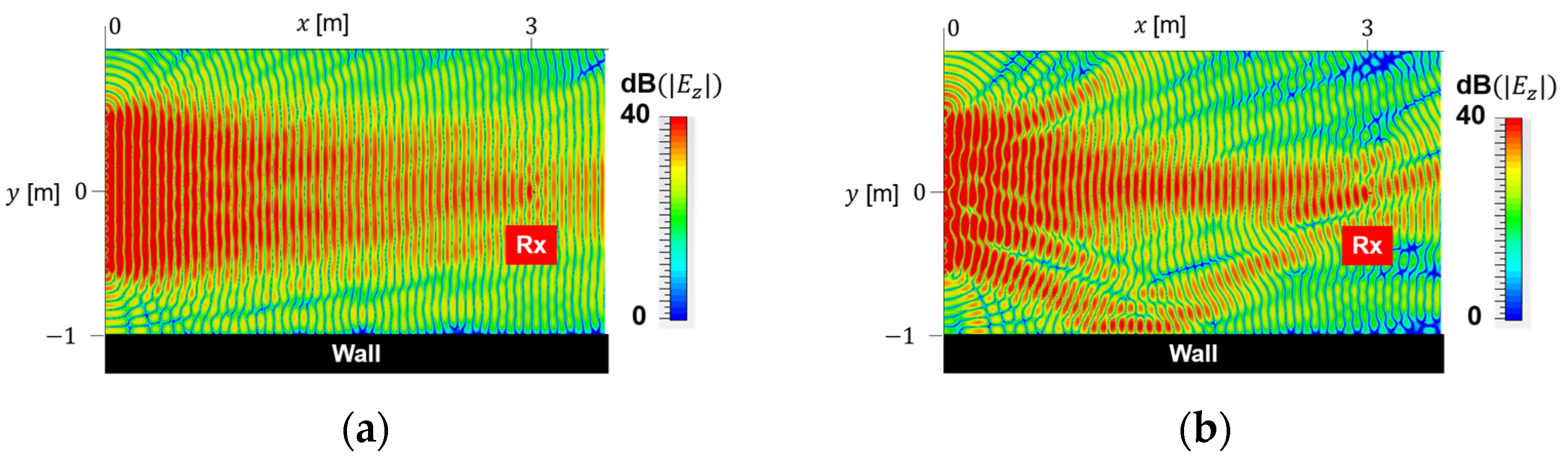
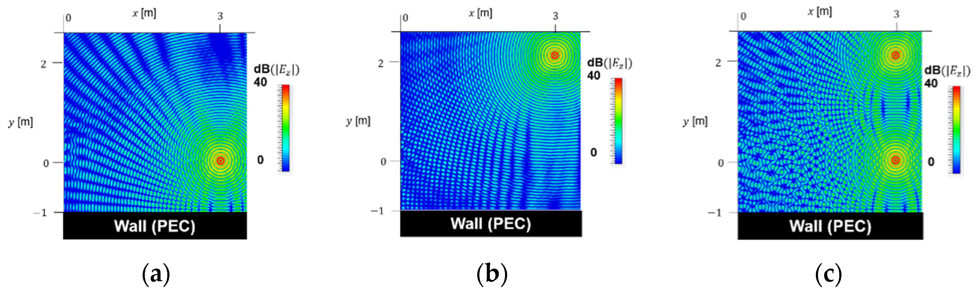
Figure 3 shows the distribution of the power transmission signal at z = 0 m with a perfect electric conductor (PEC) reflective wall at y = 1 m.
Figure 3a shows a uniform beam excited with the same phase and amplitude.
Figure 3b shows a retrodirective power transmission signal. In
Figure 3a, a single beam was formed in front of the array, and the received power was 8.1 mW. In
Figure 3b, multiple beams that consist of a direct wave and reflected wave were concentrated at the receiving point, and the received power was improved to 15 mW. In retrodirective, information of multipath of a pilot signal is reflected on a power transmission signal. Then, the multipath of all transmission signals is in phase at the power receiving point. The transmission signal became multibeam that reproduced the multipath of the pilot signal, and it made the received power higher than that of a uniform beam.
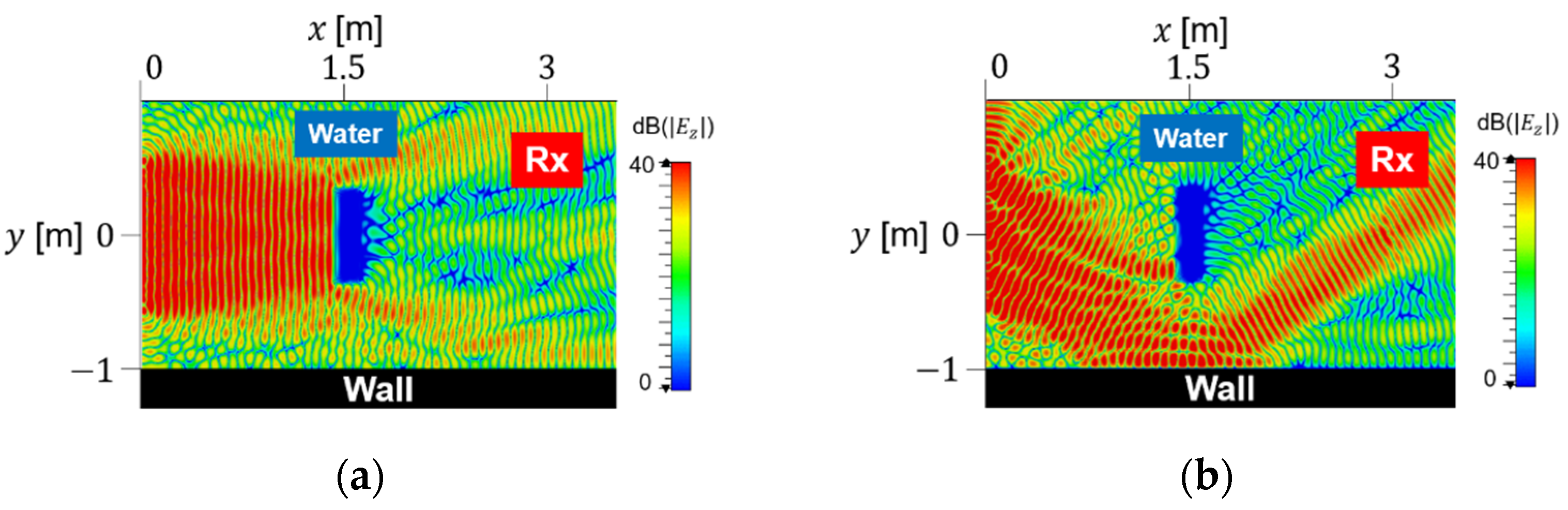
Next, we simulated a case where there is an obstacle between the transmitter and the receiver. Water cuboid at x = 1.5 m on a direct wave between transmission and reception (0.2 × 0.7 × 0.5 = 0.07 m
3, ε
r = 78, and tanδ = 0.15). Here, in addition to the received power of the receiving antenna, the absorbed power in water was calculated to examine the safety.
Figure 4a shows that the uniform beam was blocked by water, and as a result, the received power was 2.2 mW and the absorbed power in water was 1.3 W. Similarly, the direct wave of the pilot signal was blocked, and only the reflected wave reached the array. Thus, the transmission signal of the retrodirective shown in
Figure 4b reproduced only the path of the reflected wave of the pilot signal and reached the power receiving antenna, avoiding the obstacle. At this time, the received power and absorbed power in water was 10 mW and 0.41 W, respectively. Furthermore, the received power was larger than the uniform beam, while the absorbed power in water was smaller than the uniform beam. In this way, even in the presence of a shield between the transmitter and receiver, the retrodirective transmission signal was formed, avoiding the shield. Additionally, it was found that power could be transmitted safely and efficiently.
3. Retrodirective Using Amplitude Information
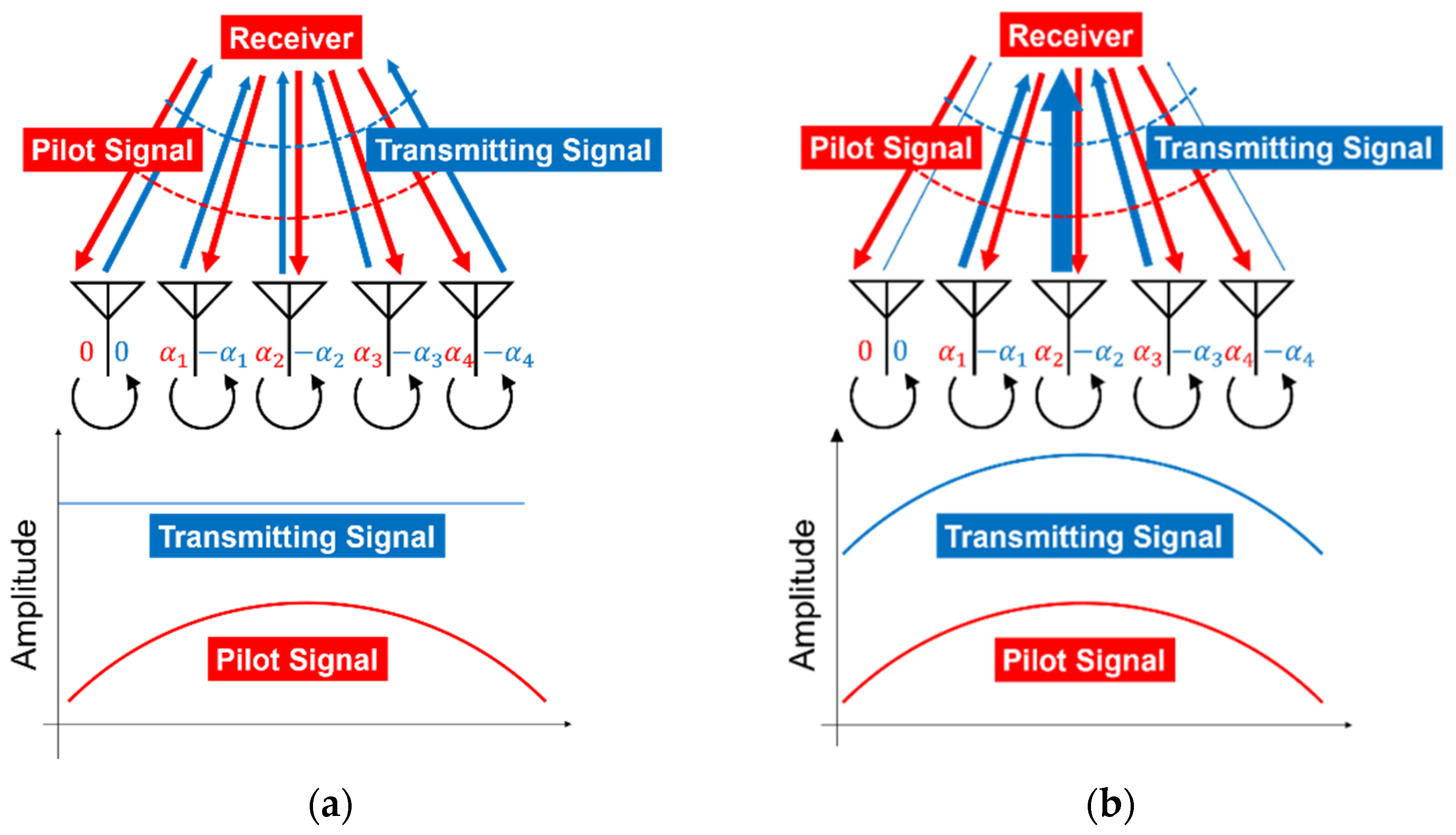
In the retrodirective discussed in
Section 2, the input power to all array elements was uniform and the signal with the inverted phase of the pilot signal was sent back, as shown in
Figure 5a. Here, we consider a method for adjusting the ratio of the input power distribution to the ratio of the pilot signal reception power, as shown in
Figure 5b. Thus, it was considered that both the phase and amplitude information of the pilot signal could be used, and more accurate beamforming could be performed.
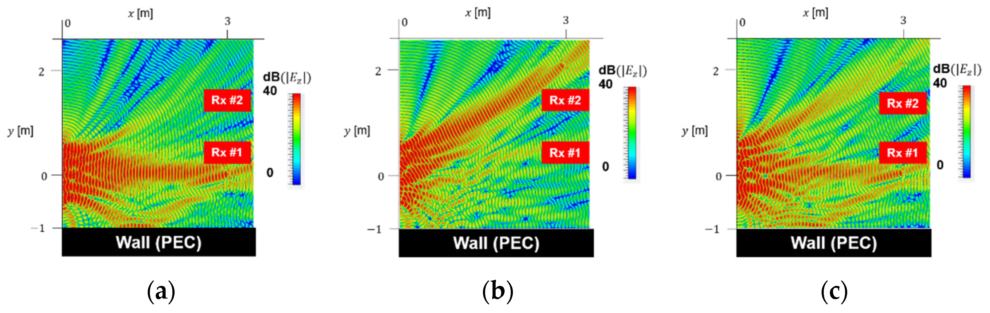
We placed a PEC wall at y = 1 m and a receiver at (Px, Py, Pz) = (3 m, 0 m, 0 m). The input power to the array was 24 W, and the input phase and amplitude were determined based on the pilot signal simulation results.
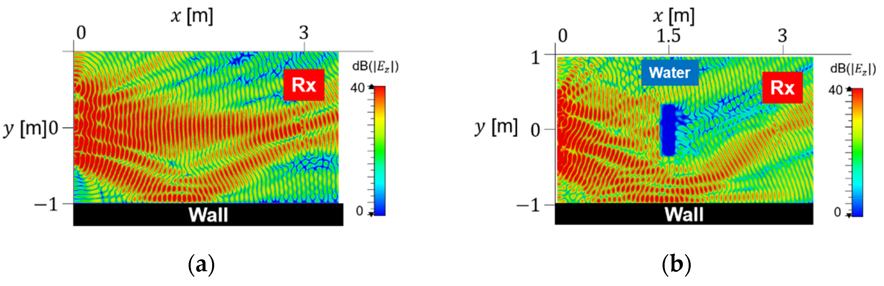
Figure 6a shows the electric field strength distribution of the retrodirective transmission signal using the amplitude information. Compared to
Figure 3b, which used uniform amplitude excitation, the power of the reflected wave path became stronger using the amplitude information, and the effect of multipath became stronger on the transmission signal. Then, the received power was 34 mW, which was more than twice the case of retrodirective using only the phase information. From the above, it can be seen that the use of the amplitude information allows the multipath of the pilot signal to be reproduced more accurately and the received power to be improved.
Next, we conducted simulations for the case where an obstacle exists between the transmitter and receiver. As in the previous section, we placed a water cuboid at x = 1.5 m, PEC wall at y = −1 m, and receiver at (Px, Py, Pz) = (3 m, 0 m, 0 m).
Figure 6b shows the electric field distribution (z = 0 m) of the power transmission signal of retrodirective using the amplitude information. The received power was 15 mW, which was increased using the amplitude information as in the case where there was no obstacle. However, there was a sidelobe toward the water, and the absorbed power of water was 0.52 W, which was higher than when only phase information was used in
Figure 4b. This outcome is presumably because the use of amplitude information greatly reflects the influence of reflection and diffraction by water. As described above, even when in the presence of an obstacle, the received power is increased by the amplitude information; however, the power absorbed by the obstacle may be increased simultaneously. When the aperture of the array antenna is made sufficiently larger than the obstacle, the effects of diffraction by it should be relatively reduced. In other words, the reception power can be increased, and the absorption power of the obstacle can be reduced by performing the retrodirective using the amplitude information containing a larger number of elements. Nevertheless, further studies are needed.
4. Retrodirective MPT for Multiple Targets
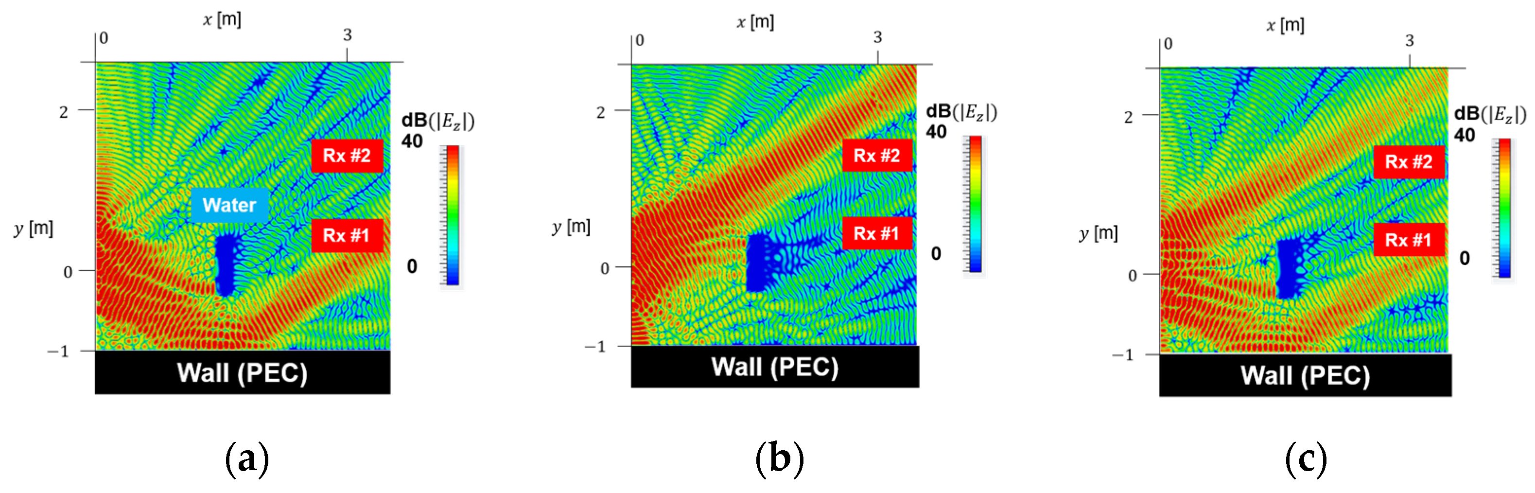
In multipath retrodirective, power is transmitted so that the phases are aligned at the positions of multiple mirror images of the receiving antenna. Even when there are multiple pilot signal sources, it is considered that the multipath of the pilot signal can be reproduced and the tracking can be performed by retrodirective. Here, when there are two power transmission targets, two antennas transmit pilot signals simultaneously and transmit power using retrodirective, and another pilot signal is transmitted for each target. We placed a PEC wall at y = −1 m, target #1 at (Px, Py, Pz) = (3 m, 0 m, 0 m), and target #2 at (Px, Py, Pz) = (3 m, 2 m, 0 m). We simulated retrodirective MPT alternately or simultaneously toward two targets. The pilot signal was transmitted alternately or simultaneously from each target, and the power transmission signal was determined based on the obtained phase and amplitude information, as shown in
Figure 7. When transmitting pilot signals simultaneously, the phase difference between the elements was 0°, and the port power was 0.5 W. The input power of the transmission signal was set to 24 W in all methods.
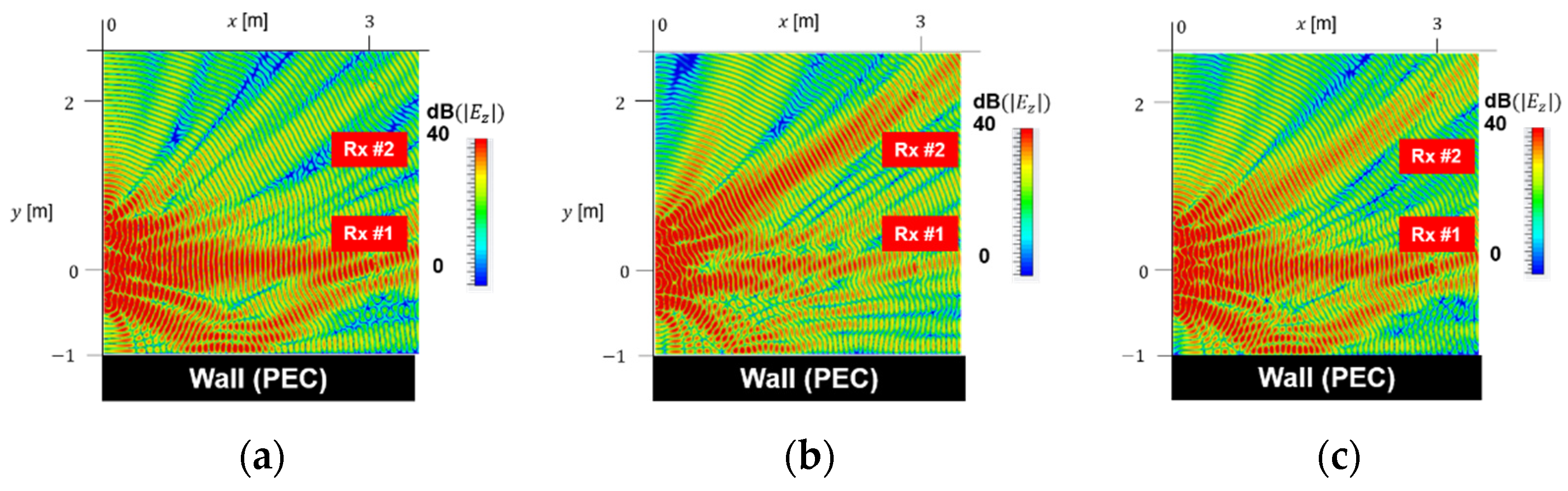
Figure 8 shows retrodirective (“ph”) using only the phase information.
Figure 9 shows retrodirective (“amph”) using both the phase and amplitude information. Even when pilot signals are transmitted from two targets simultaneously, the power transmission signal tracked both targets. In
Figure 8c and
Figure 9c, target #1 is tracked by direct and reflected waves, whereas target #2 is relatively far away from the wall. The path of the reflected wave has a small influence on tracking target #1, and only the path of the direct wave is reproduced. The received power obtained using each method is shown in
Table 1. It can be confirmed that the reception power is improved using the amplitude information.
Table 2 shows the time average of the total received power. When power was transmitted simultaneously, larger power could be transmitted than when power was transmitted alternately. In particular, in a method using amplitude information, there was a large difference between the case where power was transmitted alternately and the case where power was transmitted simultaneously. This phenomenon occurs because, even if power is transmitted simultaneously, multibeam is formed toward target #1, so the transmitted power to target #1 is not much lower than that in the case of alternating power transmission.
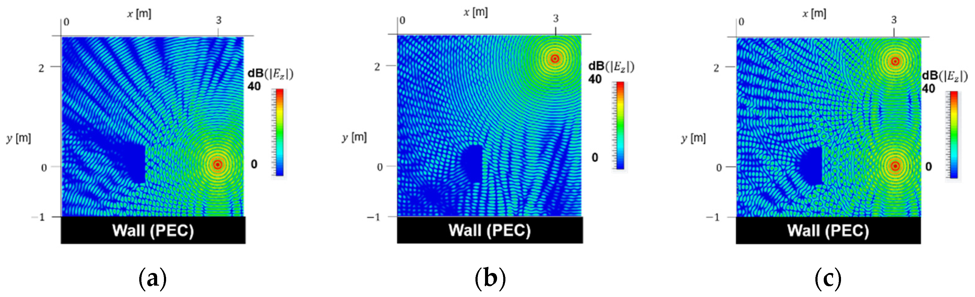
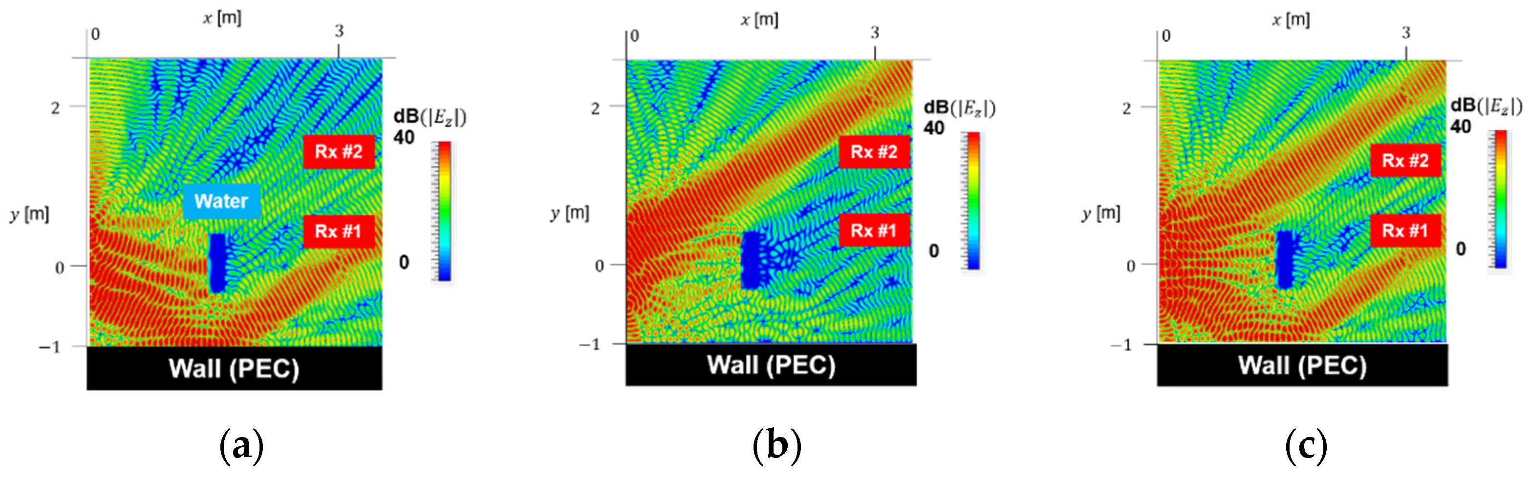
Next, we conducted simulations with a water cuboid placed at x = 1.5 m. From target #1, the direct wave was blocked, and only the reflected wave could arrive. From target #2, both direct wave and reflected wave could arrive. The pilot signal was transmitted alternately or simultaneously from each target even in the circumstance with the water cuboid as shown in
Figure 10, and the microwave power was transmitted to detected targets with the obtained phase and amplitude information (
Figure 11 and
Figure 12). Comparing
Figure 11a and
Figure 12a, for target #1 in the presence of an obstacle, the sidelobe toward water was stronger when using the amplitude information than when using only the phase information. Comparing
Figure 11b and
Figure 12b, for target #2 in the presence of an obstacle, the sidelobe toward water when using the amplitude information does not differ much from that when using only the phase information. Comparing
Figure 11c and
Figure 12c, it can be seen that the power beam toward the two targets is stronger when using the amplitude information than when using only the phase information. In each case, some sidelobes are emitted toward the water.
Table 3 shows the received power of each target, and
Table 4 shows the time average of the total received power. It can be seen that even if there are multiple targets, the reception power is improved using the amplitude information.
Table 5 shows absorbed power in water in each method. When power was transmitted only to target #1, the bottom of the water was exposed for the power beam, and the absorbed power was increased using the amplitude information. Additionally, when power was transmitted only to target #2, the water absorption power was increased using the amplitude information. As a result, the influence of multipath was reduced and no sidelobe was formed in the direction of water, so the rise of absorbed power was smaller when power was transmitted to target #2 than when power was transmitted to target #1. When transmitting power to targets #1 and #2 simultaneously, the power beam split in two directions, and the sidelobe formed between them hit the water. Using the amplitude information, the power radiated toward target #2 became stronger than that radiated toward target #1, and the sidelobe around it became also slightly stronger than those around target #1. This phenomenon made the power absorbed by water around target #2 become also slightly larger than that around target #1. However, by performing simultaneous power transmissions to both target #1 and target #2, the absorbed power was smaller than when transmitting power to only one of the targets. As described above, even when multiple targets are placed in a multipath environment, the targets can still be tracked simultaneously, and even when there is an obstacle, the optimum route is automatically selected and the targets can still be tracked. Additionally, using the amplitude information, more efficient power transmission was possible for multiple targets. Furthermore, when pilot signals from multiple targets reach the array, the effect of diffraction or reflection by an obstacle may be relatively small, thereby resulting in the effect of reducing the absorbed power in some cases.
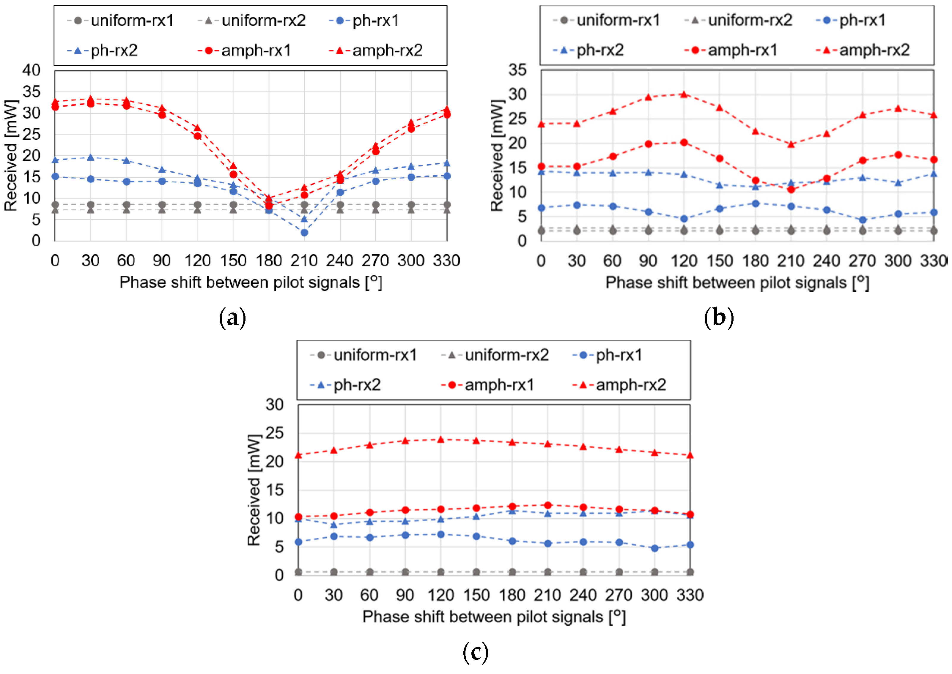
For the multiple targets, phase difference between pilot signals from multi targets are important to keep high beam efficiency. So, we carried out computer simulations with two targets when we change the distance between targets and the phase difference between the pilot signals. We placed a PEC wall at y = −1 m, target #1 at (3 m, Py, 0 m), and target #2 at (3 m, Py, 0 m), so that the distance between the two targets is 2Py. A simulation was performed when there was a phase difference φ between pilot signals from the two targets. We changed φ from 0° to 330°, and we calculated the received power at each target when 2Py = 200 m, 800 mm, and 1400 mm. The timing of excitation of the pilot signal is shifted in time region to control the phase in the simulation.
Figure 13 shows the change of received power at each target by phase shift of two pilot signals. Under any conditions, the received power of retrodirective was higher than that of the uniform beam. Further, under the same condition as the phase difference φ, similarly to the previous section, the received power is larger when the amplitude information is used. Comparing
Figure 13a,b, the difference between the received power of targets #1 and #2 when 2Py = 800 mm was larger than that when 2Py = 200 mm. In retrodirective using only the phase information, the received power of target #1 was minimum near φ = 120° and maximum near φ = 180°, but the change in received power with respect to φ when 2Py = 800 mm was smaller than that when 2Py = 200 mm. In retrodirective using the amplitude information, the received power was maximum near φ = 120° and minimum near φ = 210°. When 2Py = 1400 mm shown in
Figure 13c, it can be seen that the received power hardly changed. Since target #1 was farther away from the wall and target #2 was closer to the wall, the difference between the effects of multipath on the received power became even greater, and the difference between the received powers for targets #1 and #2 became even greater.
As described above, even when the operation on the power transmitter remains unchanged, the received power can be changed by changing the pattern of the pilot signal from the reception side, and it can be seen that the optimum power transmission signal pattern can be searched for. In the MPT method, the power receiver is smaller than the power transmitter, and the number of elements is often small. The power transmission signal can be optimized by changing the phase shift on the pilot signal from the receiver, instead of searching for an array factor composed of many elements on the power transmitter. High-speed and efficient power transmission can be realized with a small amount of calculation.
5. Experiments
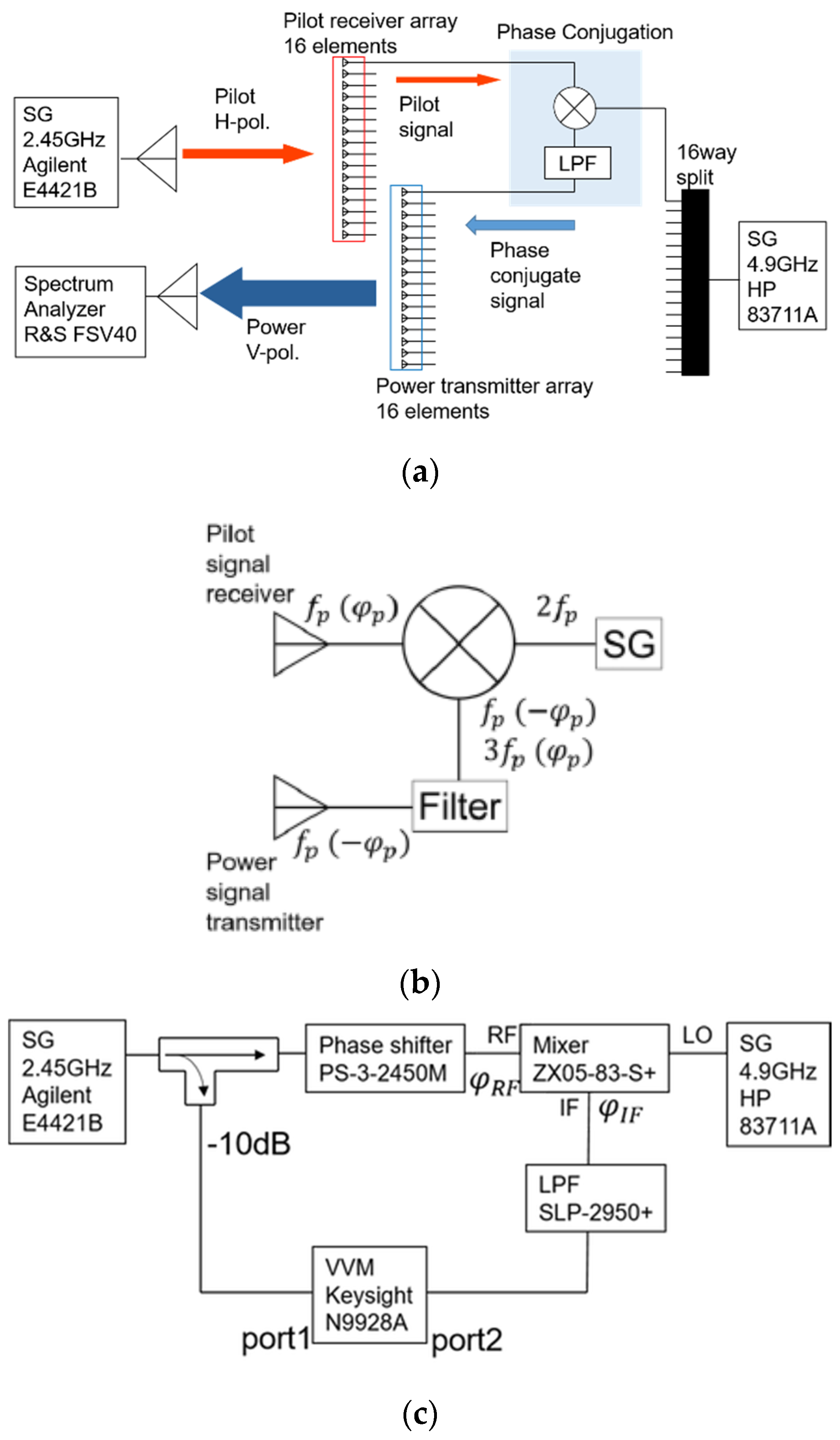
We conducted experiments to confirm the simulations. The experimental system consists of a pilot signal source, a 16-element pilot receiver array antenna, a 16-element transmitter array antenna, receiving antennas for a pilot signal (
Figure 14a), and a phase conjugation circuit (
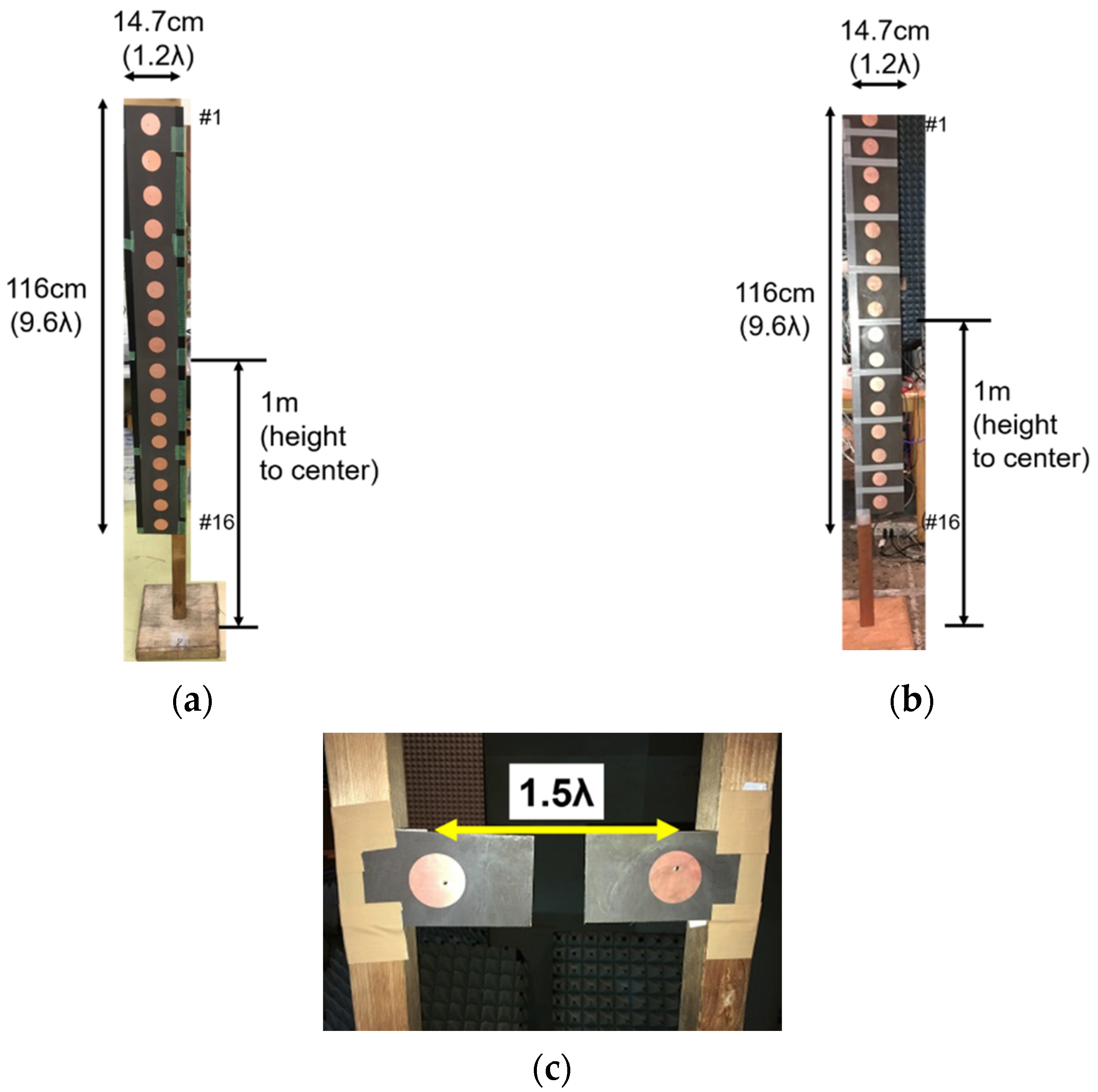
Figure 14b,c). The 2.45 GHz pilot signal with horizontal polarization was received at the 16-element array antenna (
Figure 15a) and the wireless power with vertical polarization was transmitted from the 16-element array antenna (
Figure 15b) to prevent interference between the two radio waves at the same frequency in space. The pilot signal was transmitted from two array antennas (
Figure 15c). Here, we create an antenna and verify its operation, measure the propagation characteristics of the signal from the antenna in space, verify the operation of a phase-conjugated circuit, and conduct an MPT experiment using a retrodirective system in an anechoic chamber.
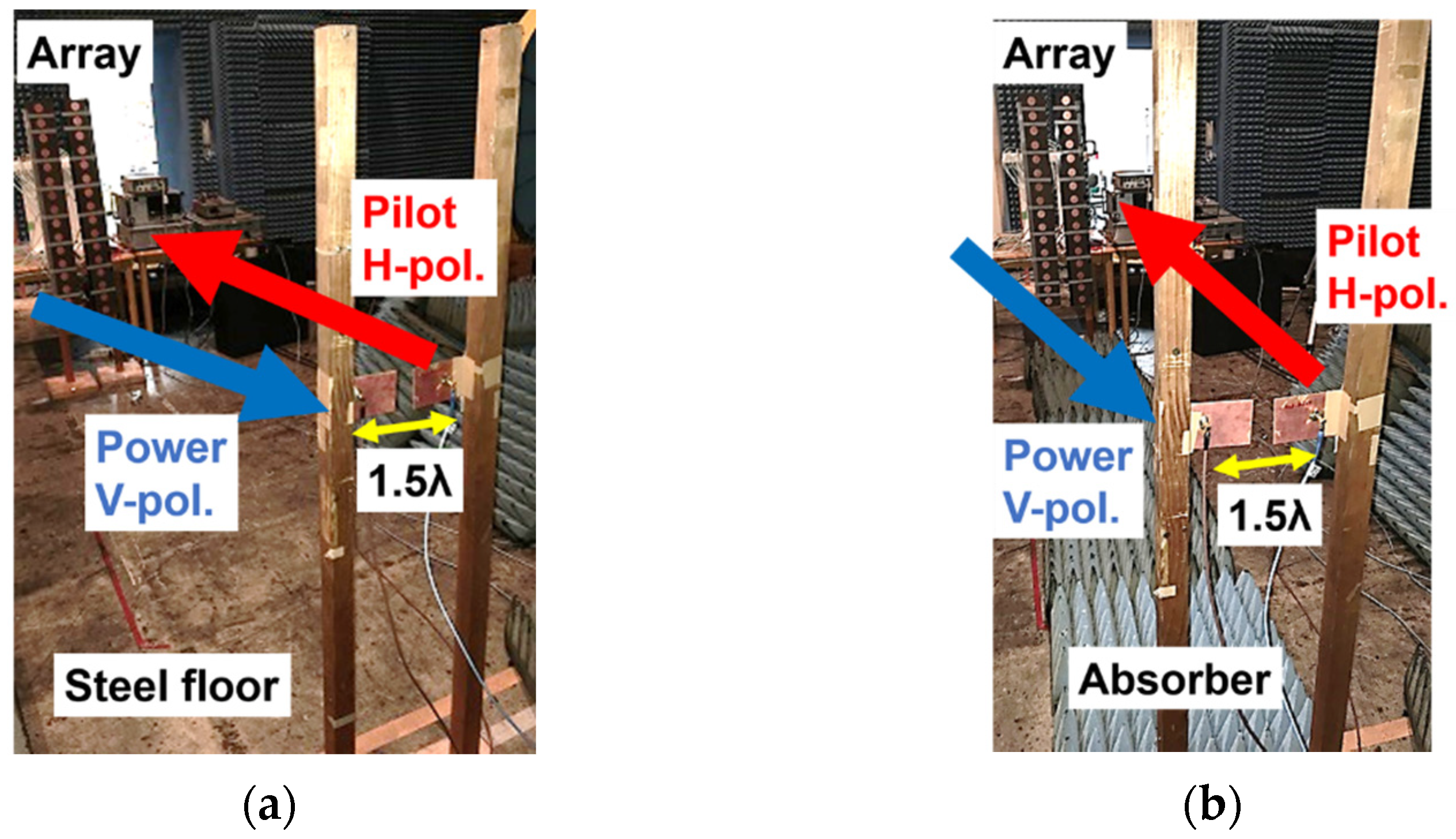
We conducted the field experiment in an anechoic chamber, as shown in
Figure 16.
Figure 16a indicates the experiment in multipath circumstance from a floor, and for comparison,
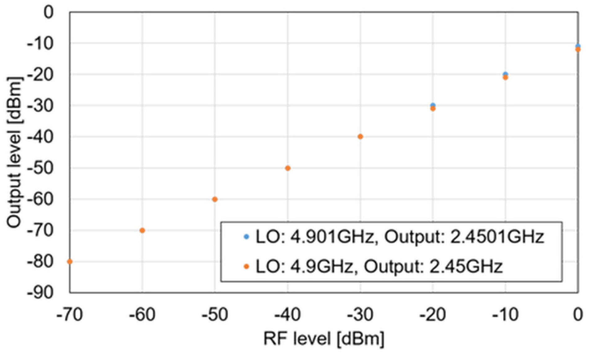
Figure 16b indicates the experiment without multipath. In the experiment, we included the effect of reflector (floor) only and there was no obstacle. We can prevent interference between the two radio waves for a pilot signal and a wireless power at the same frequency in space. However, we measured the leakage signal from the transmitting antenna to the receiving antenna, whose interference was enough to be an error factor. Therefore, in the experiment, when the pilot signal frequency was 2.4500 GHz, we changed the local oscillator (LO) frequency to 4.9001 GHz and the wireless power frequency changed to 2.4501 GHz. When we changed the LO frequency, there was no effect for a phase conjugation and a power conversion from received radio frequency (RF) (pilot signal frequency) to an output from a phase conjugation circuit (
Figure 17).
From the propagation characteristics, the conversion loss in
Figure 17, and the line loss before and after the phase-conjugated circuit (−2 dB), the received power of the pilot signal at the horizontally polarized array and the input power to the vertically polarized array were calculated. The power transmission efficiency (%) was estimated from the input power and received power of the receiving antenna. The measured power transmission efficiency and the one by simulation are shown in
Table 6. The measured results are very similar to the simulation results.
We can conclude that the proposed and developed retrodirective system was well operated.


