Article

The Impact of Temperature of the Tripping Thresholds of Intrusion Detection System Detection Circuits

by
Jarosław Łukasiak
1,
Adam Rosiński
2,* and
Michał Wiśnios
1
1
Division of Electronic Systems Exploitations, Institute of Electronic Systems, Faculty of Electronics, Military University of Technology, 2 Gen. S. Kaliski St, 00-908 Warsaw, Poland
2
Division Telecommunications in Transport, Faculty of Transport, Warsaw University of Technology, 75 Koszykowa St, 00-662 Warsaw, Poland
*
Author to whom correspondence should be addressed.
Energies 2021, 14(20), 6851; https://doi.org/10.3390/en14206851
Submission received: 17 September 2021 / Revised: 13 October 2021 / Accepted: 16 October 2021 / Published: 19 October 2021

Abstract

:
This research paper discusses issues regarding the impact of temperature on the tripping thresholds of intrusion detection system detection circuits. The objective of conducted studies was the verification of a hypothesis assuming that the variability of an intrusion detection system’s (considered as a whole) operating environment temperature can impact the electrical parameters of its detection circuits significantly enough so that it enables a change in the interpretation of the state observed within a given circuit fragment from the state of “no circuit violation” to “circuit violation”. The research covered an intrusion detection system placed in a climatic chamber with adjusted temperature (−25.1 ÷ +60.0 [°C]). The analysis of the obtained results enabled determining the relationships that allow selecting detection circuit resistor values. It is important since it increases the safety level of protected facilities through proper resistor selection, thus, correct interpretation of a detection circuit state.

1. Introduction

The document National Critical Infrastructure Protection Program includes 11 systems as part of the critical infrastructure in the Republic of Poland. They are of crucial importance to the security of the state and its citizens. Their correct functioning ensures efficient operation of public administration authorities and the entrepreneurs. Critical infrastructure includes the following systems [1]:
  • supply with power, power raw materials and fuels [2,3],
  • communications,
  • ICT networks,
  • financial [4],
  • food supply,
  • water supply,
  • health care,
  • transport [5,6],
  • emergency services,
  • ensuring continuity of the public administration operation,
  • production, deposition, storage and the use of chemicals and radioactive substances (including pipelines with hazardous substances).
One of the most important systems is transport. According to [1], it is the displacement of people, cargo (transport subject) in space, using appropriate means of transport. An efficient transport system is one of the pillars of a modern country [7]. Therefore, it is important to ensure security of objects (both stationary and mobile) participating in the transport system [8,9]. This is achieved by using, among others, electronic security systems [10,11].
Electronic security systems are composed of the following systems distinguished depending on the detected threats. These are:
  • intrusion detection systems [12,13],
  • access control systems [14,15],
  • CCTV system [16],
  • fire alarm systems [17,18,19].
The use of correctly designed alarm transmission systems [20,21,22] (including communication between vehicles and infrastructure [23]), which enables sending information from individual systems to an alarm receiving center [24] (including fire alarm system [25]) is also important.
The authors of this research paper discussed issues regarding the impact of temperature on the tripping thresholds of intrusion detection system detection circuits. This is an important issue in terms of protecting transport objects since they function under difficult environmental conditions [26,27,28], including the presence of high temperature variability [29]. Therefore, the issue of correctly defining, which state of the system can be deemed permissible or unacceptable from the point of view of security of an intrusion detection system (IDS) is important.
Wired alarm systems make the decision on recognizing an alarm based on analyzing a number of signals received via detection circuits from a wide range of sensors that can be used [30]. The most important examples of sensors include motion detectors (PIR-Passive Infra-Red and dual), magnetic, and others. The fact of them recognizing a factor classified as a threat (human presences, door and window opening, detection of gases harmful to human health and life) are signaled by a change of its electric parameters (most usually resistance), hence, the electric properties of the very detection circuit. The set of distinguishable threat states (e.g., alarm, sabotage, etc.) is defined by the number and manner of connection between EOL resistors and a given sensor. In consequence, the following configuration are distinguished: NC (Normally Closed), NO (Normally Open), EOL (End of Line), and 2EOL (alternatively DEOL—Double End of Line), which can also appear in NC and NO variants. From a practical perspective, alarm central units control the circuit state most usually through measuring the voltage drop across known resistances, which include EOL resistors, among others. A certain voltage range corresponds to each of them in a given configuration. The range can be translated to a proportional margin of permissible resistance values of the used EOL resistors.
The resistor, besides its natural feature—nominal resistance, is characterized by its tolerance coefficient, which results from the manufacturing spread. Their values are applied, in different form, virtually onto every currently manufactured resistor in the Through-Hole Technology (THT). Other important parameters, besides the aforementioned ones, include maximum power that can be generated within a characterized passive element, and also the often-forgotten temperature coefficient, which defines the nominal resistance power that can change per each temperature change of 1 [K].
The manufacturers of intrusion detection systems define their own preferred nominal values for EOL resistors. The most popular include: 1.1 [kΩ], 2.2 [kΩ], and 5.6 [kΩ]). It is not uncommon for a new IDS to be factory-fitted with a strip of several (usually approx. 15) aforementioned electronic elements in the layered technology. A photographic example of the said subassemblies is shown in Figure 1. Selected alarm systems permit the use of any EOL resistor values falling within a range specified by its manufacturer.

2. Literature Review

The impact of temperature on the functioning of common-use electronic equipment digital systems was known to the authors of this article to have been previously discussed in publications. Such examples include [31], the authors of which discussed a temperature analysis involving the reliability of key electronic subassemblies on a PCB. This enabled optimizing the arrangement of electronic subassemblies based on temperature modelling using the Finite Element Method (FEM) using Ansys software. The developed method does not change the external cooling state, but leads to reduced maximum PCB temperature, thus improving reliability indicators.
A similar approach was presented in [32], with a proposed original temperature imaging platform dedicated to monitoring temperature distribution on the surfaces of PCBs in small electronic devices and systems. A thermal imaging system using the Arduino platform and an IR temperature sensor were used to this end. This makes the method inexpensive and accessible.
The authors of [33] also elaborated on the temperature distribution in electronic devices with natural air cooling. The conducted analyses enabled developing a mathematical model for mass and thermal characteristics, which contains equations defining the optimal number of printed-circuit boards, distances between the boards, and rail width. However, it does not take into account connections with peripherals.
An important issue when determining the impact of temperature on the functioning of a studied system is taking into account a relevant temperature sensor and test circuit selection. Such considerations are included in [34]. The authors described dynamic reliability tests involving the temperature properties of electronic subassemblies. The article focuses on suggesting a measuring system for dynamic high-temperature measurements of electronic systems. Particular attention was given to the issue of the temperature sensor and signal interference arising from the application of long measuring cables from the sensor to signal conditioning and processing devices. Temperature compensation was yet another aspect of the measurements. Most usually, a studied system or device, or its temperature to be more precise, is in reality higher than that of the measuring space, since the internal electronic device is also a heat source. This can lead to a measurement error. The authors of this article minimized such errors.
The issue associated with the impact of temperature on the functioning of electronic devices is very important in terms of the security of protected property and information. Discussions in this aspect were included in [35], which analyzed the possibility of a thermal attack of cryptographic devices and electronic modules. In order to protect logic circuits against functional errors due to operation in temperatures exceeding the operating range permitted by the manufacturer, the authors suggested a prototype of an active PCB tamper system with temperature monitoring. This is a solution beneficial to system arranged on a PCB, however; it does not protect detection circuits. Similar discussions were presented in the elaboration [36], with focus on PCBs themselves and the application of dedicated paths (so-called conductive mesh). The issues associated with a thermal attack on electronic devices of security systems are significant, which is why the authors of this article focused on determining the impact of temperature on the tripping thresholds of IDS detection circuits.
Another important problem in ensuring adequate reliability of electronic systems is the application of appropriate solder. Deliberations in this area are included in [37], the authors of which conducted low-temperature reliability tests of lead solder. Such solder is used in specialized electronic devices (industrial, military, medical, aeronautics), whereas other consumer electronics utilizes lead-free solder. The publication [38] also contains discussions on temperature fatigue testing of the elements installed in the Package-on-Package (PoP) technology. Reliability was determined through monitoring resistance for test PCBs placed in a climatic chamber.
The work [39] describes climatic resistance testing of heating layers integrated in PCBs during climatic tests. The study involved climatic tests of trial PCBs with integrated “underfloor heating” aimed at preventing condensation on soldered electronic systems under specific climatic conditions. The authors conducted experiments in a climatic chamber also in the case of determining the impact of temperature on the tripping thresholds of IDS detection circuits.
The issue of ensuring adequate reliability of electronic devices already at the engineering stage is approached in numerous studies. Ref. [40] presents a method for increasing reliability of electronic subassemblies through analyzing electric, temperature and mechanical load reserves at an early engineering stage of the electronic device, based on ASONIK software. It is important to take into account maximum permissible temperatures, and vibration and shock accelerations in electronic components.
The aspects in terms of the quality of information [41] transmitted from to the device from sensors are also crucial when analyzing the impact of temperature on the tripping thresholds of IDS detection circuits. Artificial neural networks are used in some scientific studies regarding reliability and operation [42,43]. The functioning of an intrusion detection system detection circuit is also impacted by vibrations [44,45,46] but they were not included in the tests covered by this article.
Despite so many works in the field of the impact of temperature on the functioning of digital systems, there are no deliberations directly addressing the impact of temperature on the tripping thresholds of IDS detection circuits. For this purpose, the authors of this article conducted tests in this regard.
Electronic security systems, due to their particular objectives they must fulfil and the entailing high responsibility, must be characterized not only by high reliability in terms of the hardware [47,48,49], but also understood as a decision on the security of a monitored area, created based on data collected previously from the aforementioned sensors. It should be noted that, in the context of the described studies, especially the second of the aforementioned aspect may be considered as a diagnostic and measurement issue. Monitoring the voltage drop across a specific reference resistance, which includes, among others, EOL (parametric) resistors determines a diagnosis in one of the following forms—violated detection circuit, non-violated detection circuits, and sabotaged detection circuit. For obvious reasons, the manufacturers of the analyzed group of electronic systems do not publish information on the reliability and efficiency of their solutions. On one hand, this is determined by the desire to protect their intrusion detection systems against the disclosure of their potential vulnerabilities and suggesting potential intruders to concentrate their efforts on other areas. Whereas from the perspective of people and property monitored by an IDS, it seems to be a non-transparent approach, which forces a consumer to entrust his/her property, and also health, in extreme cases, solely based on manufacturer’s assurances regarding the effectiveness of the offered system, which may or may not be supported by arguments, verified and confirmed via experiments.

3. Materials and Methods

The baseline test configuration of a detection circuit within the conducted experiments was EOL, the structure of which is shown in Figure 2. This decision was determined by the fact that it is the simplest topology, which includes EOL resistors, resulting unfortunately in a lower number of distinguished detection circuit states, compared to the 2EOL variant [30].
The experimental system used was an Integra 64 control panel, hardware version 1.4 B, by a Gdańsk-based manufacturer—Satel sp. z o.o. Terminal blocks (also known as KEFA connectors) located on the PCB (Printed Circuit Board) of the IDS were coupled with, via 2.6 m (8.53 [ft]) long category 5 Alcatel Data Cable UTP flex 4PR patchable 7x.07 network cable, an INT-KLCD-GR keypad, in accordance with the guidelines in the manufacturer’s manual, taking into account the instruction for the clock signal and data line not to be routed via cables within the same twisted pair [30]. The keypad was fitted with a hardware programming interface marked USB-RS. According to the manufacturer’s guidelines, the unused programmable HV outputs of the control panel were loaded with 2.2 [kΩ] resistors included in the set. The main supply path was fed by a TRZ 50/20 transformer by Pulsar sp. j. No additional power source in the form of a maintenance-free gel battery was used. Physical terminals of the first detection circuit, via a ca. 2.58 m (8.46 [ft]) long cat. 5 AT&T-I Systimax 1061c 4/24 cm cable, with a universal multi-contact PCB. In the course of the tests, it was coupled with a factory-ready EOL resistor with a resistance of 2.2 [kΩ] and a tolerance of 5% or a hard-wired, precise, 10-rotation WXD3-13-2W potentiometer by Chengdu Guosheng Technology Co., Ltd., with a nominal value of 4.7 [kΩ], 5% tolerance, and rated power of 2 [W]. The physical connectors of the second detection circuit were directly fitted with a factory-supplied layered EOL resistor with a value of 2.2 [kΩ] and a 5% tolerance.
In addition to the aforementioned elements, the authors prepared a 2.67 m (8.76 [ft]) section of a cat. 5 AT&T-I Systimax 1061c 4/24 cm network cable. The two subsequent pairs of which had soldered factory-supplied layered EOL resistors with a tolerance of 5%, and nominal values of 2.2 [kΩ] and 1.1 [kΩ], respectively.
The motherboard of the intrusion detection system subject to experiments, fastened together with a transformer to a housing, was placed in a Lab Event L C/100/70/10 climatic chamber by Weiss Technik GmbH. A system keyboard with a communicating programming interface, detection circuit coupled with a universal multi-contact board and a network cable with soldered test EOL resistors, as well as an IDS supply cable were routed out of the chamber via temperature-tight technical bushings. The programming interface was also coupled to a computer with installed GuardX software of the manufacturer, intended for alarm system management [30]. The view and a block diagram of the test bench was presented in Figure 3 and Figure 4.
The measurements were taken as per the following methodology [50,51,52,53,54,55]. A desired temperature in the non-stop operating mode was entered on the control panel of the climatic chamber. The aforementioned function results in the device prioritizing reaching and stabilizing the preset temperature in the measuring space as fast as possible, while omitting the humidity parameter and its potential variability [50]. Next, the researchers waited until the temperature inside the chamber stabilized, with the least possible deviation. It should be noted that the available equipment, besides striving to achieve declared temperature, also ensures compensation of the heat generated by the DUT (Device Under Test) located within the measuring space. For this reason, the authors discarded connecting a backup power source in order not to unnecessarily burden the IDS control panel with the need to load a battery, which would lead to intensified heat dissipation, resulting in the chamber having to taken on its additional compensation. Summing up, the tested intrusion detection system was to operate based on the simplest possible configuration, so that the emitted heat was the lowest, which should shorten the time of reaching and stabilizing the preset temperature by the climatic chamber.
The next step involved measuring the resistance of two layered EOL resistors located in the temperature-stabilized measuring space using a Fluke 289 digital multimeter.
Next, the universal contact board was coupled with a detection circuit and a layered EOL resistor with a nominal value of 2.2 [kΩ] and a 5% tolerance. The computer run GuardX software that can be used to monitor and visualize security states of individual circuits within a tested IDS in real time. No violation of the aforementioned system fragment is depicted by a square filled with grey color. The violation (detection circuit resistance above or below the threshold value) is announced by a change in the box color to green. When the violation time exceeded a set limit, the application signaled the described event with information on failure due to prolonged violation and through alternatively changing the color of the square from grey to orange. Characterized situations are shown in Figure 5. The presence of an EOL resistor on the contact board is equivalent to lack of detection zone violation. Removing this element led to the intrusion detection system interpreting this phenomenon as a circuit violation. Remounting the subassembly into the universal contact board resulting in changing the detection zone status from “no violation” both after violation and when the resistor was installed after a prolonged period of time that was announced as a failure situation.
The course of the experiment involved repeated use of a Fluke 289 digital multimeter to determine and then record a specific resistance of the multi-turn potentiometer uncoupled from the circuit. Next, the EOL resistor was removed from the multi-contact board, which was immediately communicated as detection circuit violation. A potentiometer with a preset resistance value was used to replace the resistor, remembering about preceding this operation with uncoupling the ohmmeter. The response of the system was then observed and the conclusions recorded. The verification of IDS decision on the state of a detection circuit for each of the potentiometer setting at a preset operating temperature point was checked four times. The entire described sequence of operations was repeated after changing the operating temperature point of the climatic chamber measuring space.
In the event of declaring a detection circuit as EOL, the programming app for Satel systems (DloadX) does not distinguish between the NC and NO variants [30]. This is due to the use of upper and lower resistance thresholds, between which there is a manufacturer-determined parametric value (2.2 [kΩ]). In such a situation, exceeding the limit value determined by the upper threshold, is classified from the perspective of the control panel as infinite resistance, which corresponds to opening of the relay due to detecting a phenomenon constituting a threat in the NC variant. Whereas exceeding the lower parametric resistance threshold is diagnosed by the IDS as a short-circuit, which corresponds to a violation of the EOL NO detection circuit. An intermediate objective of the aforementioned measurements is determining the lower and upper resistance thresholds activating the parametric detection circuits within the EOL configuration.
Studying the temperature characteristics of layered EOL resistors included by the manufacturer will enable estimating the values of their temperature coefficients.

4. Results

The primary objective of the conducted experiments was to simulate extremely adverse atmospheric operating conditions for an electronic security system represented by an intrusion detection system, studying their impact on EOL resistors and the potential shift of the upper and lower parametric resistance thresholds, which when exceeded would trip an IDS alarm. These test results enabled unequivocal determination whether, assuming the overlapping of extremely adverse weather conditions, the event of a false detection circuit violation will be possible in the case of a system functioning at a minimum permissible operating temperature, with installed EOL resistor exhibiting a value at the border of the manufacturing spread, and taking into account potential displacement of parametric system trip thresholds. Similar deliberations should be related to the second boundary condition, hence, the maximum permissible operating temperature for the studied IDS. The aforementioned range for Integra control panels was specified at −10 ÷ +55 [°C]. Due to the specific significance of electronic security systems, it was decided to expand the range of test temperature in the climatic chamber to −25.1 ÷ +60.0 [°C].
The results of measuring the characteristics of layered EOL resistors are listed in Table 1. They are graphically presented in Figure 6. The result analysis clearly indicates a linear dependence of the change in the resistance of the aforementioned passive elements, as a function of temperature. This can be used as a basis to estimate the temperature coefficient for the resistors subject to testing. In the case of the resistor in question, with the nominal value of 1.1 [kΩ], the aforementioned parameter ranges from approx. 249 to 268 [ppm/K], whereas for a resistor with the nominal value of 2.2 [kΩ], this parameter falls in the range of approx. 482 ÷ 529 [ppm/K]. This enables a conclusion that in the case of both analyzed EOL resistors, their temperature coefficient value intervals fall within the range of values typical for layered resistors.
Continuing the discussion, it might be worthwhile to determine the change in the resistance of individual EOL resistors upon significant temperature deviations, relative to room temperature (25.0 [°C]), adopted as the reference point. Further analysis of the conducted experiment results indicates that a resistor with the nominal value of 1.1 [kΩ], upon a temperature change in the range of +25.0 ÷ +60.0 [°C], changes the value of its primary parameter by 0.0090 [Ω] and by 0.0132 [Ω], for a temperature range of +25.0 ÷ −25.1 [°C]. In the case of an EOL resistor with the nominal value of 2.2 [kΩ], and at similar temperature ranges, resistance changes equal to 0.0176 [Ω] and 0.0261 [Ω], respectively. Table 1 lists the results of the analysis above.
Given the 5% manufacturing spread in the studied resistors, the range of statistically achievable real resistances of the resistors with the nominal values of 1.1 [kΩ] and 2.2 [kΩ] can be estimated. The aforementioned ranges are summarized in Table 2.
Assuming the superpositions of extremely adverse circumstances related to boundary cases for all previous deliberations, it is possible to determine the ranges for the variability of nominal resistance in the tested EOL resistors. The aforementioned data is shown in Table 3.
In order to be able to clearly state whether the aforementioned extreme cases can have a significant impact on the ultimate decision of the intrusion detection system regarding the diagnosis on the state of the detection circuit, the results from Table 3 should be compared with the results of measurements aimed at determining the threshold values for parametric resistances, which determine the change of the detection circuit state from “no violation” to “violated”. Characterized test outcomes are listed in Table 4, while for the sake of result presentation clarity, the “detection circuit violated” state has been assigned the red color. The aforementioned designation was assigned to results that were signaled by GuardX software as a too long violation for all measurements at a given operating temperature points. Green color was allocated to the results that lead to a constant message on the lack of detection circuit violation for all four test trials. Orange was assigned to ambiguous results, i.e., those which were composed of any combination of the aforementioned states in four measurements at a given operating temperature point, with a specified setting of the multi-turn precise potentiometer. It should be noted that despite the availability of a very advanced climatic chamber, the authors experienced temperature deviations relative to the values preset on the control panel, the range of which is included in Table 4. The system in question, just like every other electronic device, transforms some of the electric power consumed for operating purposes it was designed to and to process data, into heat as the loss power. In such a case, the task of the climatic chamber was not only to maintain a constant temperature within its measuring space, but also to provide follow-up compensation of the thermal energy generated by the system under test.
When analyzing raw measurement data from Table 4 and dividing the sets of obtained detection circuit state by color into no violation (green), uncertain state (orange), and certain alarm state (red), one can almost immediately observe that the resistance determining the upper and lower detection circuit tripping thresholds grow as a temperature function. The last resistances corresponding to the non-violation state of a detection circuit, preceded solely by measurement points representing a state of certain non-violation were adopted as the limit values. For this reason, the result of 2.8383 [kΩ] for a temperature of 25.0 ± 0.2 [°C] could not be considered as the detection circuit upper tripping threshold. A graphical interpretation of the characterized data is shown in Figure 7 and Figure 8. Only then, one can notice a non-linear relationship between the values in question. The accuracy of conducted measurement can be proved by an almost unchanged bandwidth of the resistance values corresponding to the state of absolute detection circuit non-violation (difference between the obtained upper and lower thresholds for each test temperatures), which is approx. 1.31 [kΩ] for the range of +60.0 ÷ −25.00 [°C], and decreases only by 9.1 [Ω]. Assuming the resistance of 2.2 [kΩ] as a point that should mark the middle of the band of values corresponding to the absolute detection circuit non-violation state, and based on the obtained results, it should be concluded that the aforementioned ranges are not symmetrical, starting already at room temperature. In the case of the measurement series in question, the 2.2 [kΩ] resistance and the upper threshold are separated by approx. 636 [Ω]. In the case of the lower threshold and the reference value, this range is equal to 673 [Ω]. Moreover, the observed disproportion worsens along with dropping temperature.
It should be noted that prior to conducting the primary tests, the authors also performed preliminary testing based on the 8143R10KL.25 precise multi-turn potentiometer by TT Electronics. The obtained results were similar with all of the presented above. The universal multi-contact board and elements used within the experiments are shown in Figure 9. In order to achieve better accuracy, the used adjusting element was changed to one ensuring better measurement resolution (instead of 10 [kΩ] per ten rotations to 4.7 [kΩ] per ten rotations).
The obtained upper and lower limit resistance thresholds allow for a conclusion that maintaining an adequate, safe resistance margin enables installers of the tested IDS to use EOL resistors with a value different than the one declared by the manufacturer. The author of this study, due to the range of values corresponding to the absolute detection circuit state of non-violation, compared to the factory-set value of 2.2 [kΩ] suggested two relationships, which enable determining the maximum and minimum value of a resistor, installing within a circuit will allow an intrusion detection system to function without impacting the diagnostic reliability in terms of the state within a specific, real detection circuit. In the case of the maximum resistors value, it was assumed that the installed passive element would be characterized by a 5 [%] tolerance. The proposed formula also takes into account the resistivity of a cable in a detection circuit, the total value of which has to be determined by the installed alone, and has to be used based on a catalogue card provided with the cabling, combined with the knowledge on the length of the created detection circuit. It was also assumed that the maximum value of the resistor used within a given tolerance cannot exceed the value separated from the lowest of them, and obtained via measurements of the upper threshold value (i.e., 2.8305 [kΩ] at −25.1 [°C]) with a 25% safety margin. The aforementioned consideration led to a relationship (1)
1.05 x + y = 0.75 2.8305 ,
after transformations we get a Formula (2) for the maximum value of resistance suitable for practical application within a specific detection circuit of an intrusion detection system, expressed in [kΩ],
x = 2.122875 y 1.05   [ k ] ,
where:
y-resistivity of the cable making up the detection circuit (please remember to take into account both the section from the IDS control panel to the resistor in the sensor and about the same-length cable coupled in the opposite direction).
Similar considerations apply to the minimum resistor value suitable for application as an EOL resistors, with the difference in that the use of the aforementioned passive element with a value lower than critical cannot exceed 25% of the security margin, relative to the highest lower threshold value (resulting in the narrowest range of resistance values, relative to the one preset by the manufacturer—2.2 [kΩ]). In this case, this was a value of 1.5303 [kΩ] obtained at a temperature of +60.0 [°C]. Given the aforementioned assumptions, the following formula was obtained
0.95 x + y = 0.75 1.5303 ,
which after transformation provides an equation,
x = 1.147725 y 0.95   [ k ] ,
where:
y-resistivity of the cable making up the detection circuit (please remember to take into account both the section from the IDS control panel to the resistor in the sensor and about the same-length cable coupled in the opposite direction).
It should be stressed that the adopted 25% safety margin is aimed at including the temperature coefficient of the EOL resistor and a change in the resistivity of cables comprising a detection circuit due to ambient temperature changes.

5. Discussion and Conclusions

Given the obtained results of the experiment involving the impact of IDS operating environment temperature on tripping thresholds of individual detection circuit states and taking into account the measured temperature characteristics of real EOL resistors, it should be clearly concluded that there is no risk of a false alarm within the analyzed solution, caused by the aforementioned factor. The resistance variability in the case of considered passive elements, also given the range of temperature significantly exceeding typical environmental conditions specified by the manufacturer of the tested solution, is so small that it is impossible to approach typical thresholds changing individual detection circuit states (adopted as limit resistance values at room temperature). It should be stated that taking into account the observed minor deviations of limit resistances as a function of temperature will also not influence the reliability of distinguishing between the states of an IDS detection circuit. The deliberations prove that, assuming the case with the superposition of the most adverse conditions (i.e., overlapping of limit resistance threshold shift at an extreme temperature, causing the highest resistance changes, possible highest change in the resistance of the attached EOL resistor induced by the aforementioned extreme temperature, and the installation of a studied passive element, the value of which is a limit case of resistance falling within the 5% manufacturing spread determined by the manufacturer) will also not cause a misinterpretation of the current state of the detection circuit state.
Naturally, it should be noted that although the obtained results clearly indicate the correctness of the studied IDS design and the lack of a need to repeat the tests for other detection circuit configurations (e.g., 2EOL), it does not exclude the justification of repeating similar experiments not only for alarm control panel families of the same manufacturer (to a lesser extent), but above all, for solutions of their competitors. In this case aimed at detecting potential design errors, which involve the failure to predict or assuming too narrow resistance ranges, corresponding to individual states of detection circuits, which will naturally translate to very narrow voltage drop ranges.

Author Contributions

Conceptualization, J.Ł., A.R. and M.W.; Methodology, J.Ł. and M.W.; Validation, J.Ł. and A.R.; Formal analysis, J.Ł. and M.W.; Investigation, J.Ł. and A.R.; Resources, J.Ł. and M.W.; Data curation, J.Ł.; Writing—original draft preparation, J.Ł., A.R. and M.W.; Writing—review and editing, J.Ł., A.R. and M.W.; Visualization, J.Ł.; Supervision, A.R.; Project administration, A.R.; Funding acquisition, A.R. All authors have read and agreed to the published version of the manuscript.

Funding

This research received no external funding.

Institutional Review Board Statement

Not applicable.

Informed Consent Statement

Not applicable.

Data Availability Statement

The data presented in this study are available on request from the corresponding author.

Conflicts of Interest

The authors declare no conflict of interest.

References

  1. Government Security Center. National Critical Infrastructure Protection Programme in Poland. August 2020. Available online: https://www.gov.pl/attachment/ee334990-ec9c-42ab-ae12-477608d94eb1 (accessed on 18 August 2021).
  2. An, J.; Mikhaylov, A.; Richter, U.H. Trade War Effects: Evidence from Sectors of Energy and Resources in Africa. Heliyon 2020, 6, e05693. [Google Scholar] [CrossRef]
  3. An, J.; Mikhaylov, A. Russian energy projects in South Africa. J. Energy South. Afr. 2020, 31, 58–64. [Google Scholar] [CrossRef]
  4. Mishina, V.Y.; Khomyakova, I.I. Dedollarization and settlements in national currencies: Eurasian and Latin American experience. Vopr. Ekon. 2020, 9, 61–79. [Google Scholar] [CrossRef]
  5. Gołębiowski, P.; Jacyna, M.; Stańczak, A. The Assessment of Energy Efficiency versus Planning of Rail Freight Traffic: A Case Study on the Example of Poland. Energies 2021, 14, 5629. [Google Scholar] [CrossRef]
  6. Jacyna, M.; Żochowska, R.; Sobota, A.; Wasiak, M. Scenario Analyses of Exhaust Emissions Reduction through the Introduction of Electric Vehicles into the City. Energies 2021, 14, 2030. [Google Scholar] [CrossRef]
  7. Losurdo, F.; Dileo, I.; Siergiejczyk, M.; Krzykowska, K.; Krzykowski, M. Innovation in the ICT Infrastructure as a Key Factor in Enhancing Road Safety: A Multi-Sectoral Approach. In Proceedings of the 2017 25th International Conference on Systems Engineering (ICSEng), Las Vegas, NV, USA, 22–24 August 2017; Selvaray, H., Chmaj, G., Zydek, D., Eds.; The Institute of Electrical and Electronics Engineers, Inc.: Danvers, MA, USA, 2017; pp. 157–162. [Google Scholar] [CrossRef]
  8. Kierzkowski, A.; Kisiel, T. Simulation model of security control system functioning: A case study of the Wroclaw Airport terminal. J. Air Transport. Manag. 2017, 64, 173–185. [Google Scholar] [CrossRef]
  9. Siergiejczyk, M.; Paś, J.; Dudek, E. Reliability analysis of aerodrome’s electronic security systems taking into account electromagnetic interferences. In Proceedings of the Safety and Reliability—Theory and Applications, Proceedings of the 27th European Safety and Reliability Conference (Esrel 2017), Portorož, Slovenia, 18–22 June 2017; Čepin, M., Briš, R., Eds.; CRC Press/Balkema: Schipholewh, The Netherlands, 2017; pp. 2285–2292. [Google Scholar] [CrossRef]
  10. Fischer, R.J.; Halibozek, E.P.; Walters, D.C. Introduction to Security, 10th ed.; Butterworth-Heinemann: Oxford, UK, 2019. [Google Scholar] [CrossRef]
  11. Purpura, P.P. Security and Loss Prevention: An Introduction; Butterworth-Heinemann: Oxford, UK, 2019. [Google Scholar] [CrossRef]
  12. Valouch, J. Technical requirements for Electromagnetic Compatibility of Alarm Systems. Int. J. Circuits Syst. Signal Process. 2015, 9, 186–191. Available online: https://www.naun.org/main/NAUN/circuitssystemssignal/2015/a522005-196.pdf (accessed on 10 July 2021).
  13. Urbancokova, H.; Valouch, J.; Adamek, M. Testing of an intrusion and hold-up systems for electromagnetic susceptibility—EFT/B. Int. J. Circuits Syst. Signal Process. 2015, 9, 40–46. Available online: https://www.naun.org/main/NAUN/circuitssystemssignal/2015/a122005-024.pdf (accessed on 10 July 2021).
  14. Wiśnios, M.; Paś, J. The assessment of exploitation process of power for access control system. E3S Web Conf. 2017, 19, 01034. [Google Scholar] [CrossRef] [Green Version]
  15. Wiśnios, M.; Dąbrowski, T.; Bednarek, M. The security increasing level method provided by biometric access control system. Przegląd Elektrotechniczny 2015, 91, 229–232. [Google Scholar] [CrossRef]
  16. Paś, J.; Rosiński, A.; Białek, K. A reliability-operational analysis of a track-side CCTV cabinet taking into account interference. Bull. Pol. Acad. Sci. Tech. Sci. 2021, 69, e136747. [Google Scholar] [CrossRef]
  17. Klimczak, T.; Paś, J. Basics of Exploitation of Fire Alarm Systems in Transport Facilities; Military University of Technology: Warsaw, Poland, 2020. [Google Scholar]
  18. Jakubowski, K.; Paś, J. Determination of the performance parameters of selected electronic safety systems based on the process of their use in critical infrastructure facilities. Przegląd Elektrotechniczny 2021, 97. [Google Scholar] [CrossRef]
  19. Paś, J.; Klimczak, T. Selected issues of the reliability and operational assessment of a fire alarm system. Eksploat. I Niezawodn. Maint. Reliab. 2019, 21, 553–561. [Google Scholar] [CrossRef]
  20. Krzykowska-Piotrowska, K.; Dudek, E.; Siergiejczyk, M.; Rosiński, A.; Wawrzyński, W. Is Secure Communication in the R2I (Robot-to-Infrastructure) Model Possible? Identification of Threats. Energies 2021, 14, 4702. [Google Scholar] [CrossRef]
  21. Jacyna, M.; Szczepański, E.; Izdebski, M.; Jasiński, S.; Maciejewski, M. Characteristics of event recorders in Automatic Train Control systems. Arch. Transport 2018, 46, 61–70. [Google Scholar] [CrossRef]
  22. Polak, R.; Laskowski, D.; Matyszkiel, R.; Łubkowski, P.; Konieczny, Ł.; Burdzik, R. Optimizing the Data Flow in a Network Communication between Railway Nodes. In Research Methods and Solutions to Current Transport Problems, Proceedings of the International Scientific Conference Transport of the 21st Century, Advances in Intelligent Systems and Computing, Ryn, Poland, 9–12 June 2019; Siergiejczyk, M., Krzykowska, K., Eds.; Springer: Cham, Switzerland, 2020; Volume 1032, pp. 351–362. [Google Scholar] [CrossRef]
  23. Kossakowski, D.; Krzykowska, K. Application of V2X Technology in Communication between Vehicles and Infrastructure in Chosen Area. In Research Methods and Solutions to Current Transport Problems, Proceedings of the International Scientific Conference Transport of the 21st Century, Advances in Intelligent Systems and Computing, Ryn, Poland, 9–12 June 2019; Siergiejczyk, M., Krzykowska, K., Eds.; Springer: Cham, Switzerland, 2020; Volume 1032, pp. 247–256. [Google Scholar] [CrossRef]
  24. Klimczak, T.; Paś, J. Reliability and operating analysis of transmission of alarm signals of distributed fire signaling system. J. KONBiN 2019, 49, 165–174. [Google Scholar] [CrossRef] [Green Version]
  25. Bednarek, M.; Dąbrowski, T.; Olchowik, W. Selected practical aspects of communication diagnosis in the industrial network. J. KONBiN 2019, 49, 383–404. [Google Scholar] [CrossRef] [Green Version]
  26. Paś, J.; Rosiński, A.; Białek, K. A reliability-exploitation analysis of a static converter taking into account electromagnetic interference. Transport Telecommun. 2021, 22, 217–229. [Google Scholar] [CrossRef]
  27. Paś, J.; Jakubowski, K. Indicator Analysis of Security Risk for Electronic Systems Used to Protect Field Command Posts of Army Groupings. J. KONBiN 2020, 50, 43–61. [Google Scholar] [CrossRef]
  28. Chmielińska, J.; Kuchta, M.; Kubacki, R.; Dras, M.; Wierny, K. Selected methods of electronic equipment protection against electromagnetic weapon. Przegląd Elektrotechniczny 2016, 92, 1–8. [Google Scholar] [CrossRef]
  29. Stypułkowski, K.; Gołda, P.; Lewczuk, K.; Tomaszewska, J. Monitoring System for Railway Infrastructure Elements Based on Thermal Imaging Analysis. Sensors 2021, 21, 3819. [Google Scholar] [CrossRef]
  30. Polish-European Standard. PN-EN 50131-1:2009. Alarm Systems—Intrusion and Hold-up Systems—Part. 1: System Requirements; Polish Committee for Standardization: Warsaw, Poland, 2009. [Google Scholar]
  31. Xu, S.; Li, X. Analysis on thermal reliability of key electronic components on PCB board. In Proceedings of the 2011 International Conference on Quality, Reliability, Risk, Maintenance, and Safety Engineering, Xi’an, China, 17–19 June 2011; Huang, H.-Z., Zuo, M.J., Jia, X., Liu, Y., Eds.; IEEE: Xi’an, China, 2011; pp. 52–54. [Google Scholar] [CrossRef]
  32. Milic, M.; Ljubenovic, M. Arduino-Based Non-Contact System for Thermal-Imaging of Electronic Circuits. In Proceedings of the 2018 Zooming Innovation in Consumer Technologies Conference (ZINC), Novi Sad, Serbia, 30–31 May 2018; pp. 62–67. [Google Scholar] [CrossRef]
  33. Shilo, G.; Ogrenich, E.; Kulyaba-Kharitonova, T.; Buhaiev, O. Thermal design of the Electronic Equipment Enclosures with Natural Air Cooling. In Proceedings of the 9th International Conference on Advanced Computer Information Technologies (ACIT), Ceske Budejovice, Czech Republic, 5–7 June 2019; pp. 153–156. [Google Scholar] [CrossRef]
  34. Qiang, G.; Ya, Z.; Jinhua, Z. Dynamic Reliability Testing about Temperature Characteristic of Components. In Proceedings of the 2009 International Conference on Wireless Networks and Information Systems, Shanghai, China, 28–29 December 2009; Luo, Q., Tan, H., Eds.; IEEE: Los Alamitos, CA, USA, 2009; pp. 257–258. [Google Scholar] [CrossRef]
  35. Vasile, D.C.; Svasta, P.M. Temperature sensitive active tamper detection circuit. In Proceedings of the 2017 IEEE 23rd International Symposium for Design and Technology in Electronic Packaging (SIITME), Constanta, Romania, 26–29 October 2017; IEEE: Piscataway Township, NJ, USA, 2017; pp. 175–178. [Google Scholar] [CrossRef]
  36. Vasile, D.-C.; Svasta, P.; Pantazică, M. Preventing the Temperature Side Channel Attacks on Security Circuits. In Proceedings of the 2019 IEEE 25th International Symposium for Design and Technology in Electronic Packaging (SIITME), Cluj-Napoca, Romania, 23–26 October 2019; IEEE: Piscataway Township, NJ, USA, 2019; pp. 244–247. [Google Scholar] [CrossRef]
  37. Wang, X.; Liu, X.; Ding, Y.; Hang, C.; Wu, G.; Liu, W.; Li, J. Study on the Low Temperature Reliability of Leaded Solder. In Proceedings of the 2020 21st International Conference on Electronic Packaging Technology (ICEPT), Guangzhou, China, 12–15 August 2020; IEEE: Piscataway Township, NJ, USA, 2020; pp. 1–5. [Google Scholar] [CrossRef]
  38. Kościelski, M.; Sitek, J. Influence of soldering condition on structure and reliability of solder joints made in Package-on-Package technology. In Proceedings of the 2016 6th Electronic System-Integration Technology Conference (ESTC), Grenoble, France, 13–15 September 2016; IEEE: Piscataway Township, NJ, USA, 2016; pp. 1–4. [Google Scholar] [CrossRef]
  39. Seehase, D.; Novikov, A.; Nowottnick, M. Resistance development on embedded heating layers during climatic test. In Proceedings of the 2017 21st European Microelectronics and Packaging Conference (EMPC) & Exhibition, Warsaw, Poland, 10–13 September 2017; Dziedzic, A., Jasiński, P., Eds.; IEEE: Neumarkt-St. Veit, Germany, 2017; pp. 1–5. [Google Scholar] [CrossRef]
  40. Kofanov, Y.N.; Sotnikova, S.Y.; Subbotin, S.A. Method of increasing the reliability of on-board electronic equipment with an analysis of reserves for the electrical, thermal and mechanical loads. In Proceedings of the 2016 IEEE Conference on Quality Management, Transport and Information Security, Information Technologies (IT&MQ&IS), Nalchik, Russia, 4–11 October 2016; Shaposhnikov, S., Ed.; IEEE Russia North West Section: St. Petersburg, Russia, 2016; pp. 94–98. [Google Scholar] [CrossRef]
  41. Stawowy, M.; Olchowik, W.; Rosiński, A.; Dąbrowski, T. The Analysis and Modelling of the Quality of Information Acquired from Weather Station Sensors. Remote Sens. 2021, 13, 693. [Google Scholar] [CrossRef]
  42. Duer, S.; Duer, R.; Mazuru, S. Determination of the expert knowledge base on the basis of a functional and diagnostic analysis of a technical object. Nonconv. Technol. Rev. 2016, 20, 23–29. Available online: http://revtn.ro/index.php/revtn/article/view/115/76 (accessed on 10 July 2021).
  43. Duer, S. Assessment of the Operation Process of Wind Power Plant’s Equipment with the Use of an Artificial Neural Network. Energies 2020, 13, 2437. [Google Scholar] [CrossRef]
  44. Burdzik, R.; Konieczny, Ł.; Figlus, T. Concept of on-board comfort vibration monitoring system for vehicles. In Proceedings of the Communications in Computer and Information Science, Activities of Transport Telematics 13th International Conference on Transport Systems Telematics, TST 2013, Katowice-Ustroń, Poland, 23–26 October 2013; Mikulski, J., Ed.; Springer: Berlin/Heidelberg, Germany, 2013; Volume 395, pp. 418–425. [Google Scholar] [CrossRef]
  45. Kostrzewski, M. Analysis of selected acceleration signals measurements obtained during supervised service conditions—Study of hitherto approach. J. Vibroeng. 2018, 20, 1850–1866. [Google Scholar] [CrossRef] [Green Version]
  46. Kukulski, J.; Jacyna, M.; Gołębiowski, P. Finite Element Method in Assessing Strength Properties of a Railway Surface and Its Elements. Symmetry 2019, 11, 1014. [Google Scholar] [CrossRef] [Green Version]
  47. Paś, J.; Siergiejczyk, M. Interference impact on the electronic safety system with a parallel structure. Diagnostyka 2016, 17, 49–55. Available online: http://www.diagnostyka.net.pl/pdf-62677-17828?filename=Interference%20impact%20on.pdf (accessed on 10 July 2021).
  48. Suproniuk, M.; Paś, J. Analysis of electrical energy consumption in a public utility buildings. Przegląd Elektrotech. 2019, 95, 97–100. [Google Scholar] [CrossRef]
  49. Łukasiak, J.; Rosiński, A. Analysis of exploitation process in the aspect of readiness of electronic protection systems. Diagnostyka 2017, 18, 37–42. Available online: http://www.diagnostyka.net.pl/pdf-79784-17618?filename=Analysis%20of%20exploitation.pdf (accessed on 10 July 2021).
  50. Military Handbook. Reliability/Design Thermal Applications; MIL-HDBK-251; Department od Defence: Washington, DC, USA, 1978.
  51. Ćwirko, J.; Ćwirko, R. Temperature testing of electronic modules. Biul. WAT 2008, LVII, 133–142. [Google Scholar]
  52. Polish-European Standard. PN-EN 50130-5:2012. Alarm Systems—Part. 5: Environmental Test Methods; Polish Committee for Standardization: Warsaw, Poland, 2012. [Google Scholar]
  53. Defense Standard. NO-04-A004-1:2016. Military Installations—Alarm Systems—Part 1: General Requirements; Military Centre for Standardization, Quality and Codification: Warsaw, Poland, 2016. [Google Scholar]
  54. Polish-European Standard. PN-EN IEC 60721-3-3:2019-10. Classification of Environmental Conditions—Part 3-3: Classification of Groups of Environmental Parameters and Their Severities—Stationary Use at Weatherprotected Locations; Polish Committee for Standardization: Warsaw, Poland, 2019. [Google Scholar]
  55. Polish-European Standard. PN-EN IEC 60721-3-4:2019-10. Classification of Environmental Conditions—Part 3-4: Classification of Groups of Environmental Parameters and Their Severities—Stationary Use at Non-Weatherprotected Locations; Polish Committee for Standardization: Warsaw, Poland, 2019. [Google Scholar]
Figure 1. Typical layered EOL resistors fitted as equipment for intrusion detection systems (IDS).
Energies 14 06851 g001
Figure 2. Structure of a parametric detection circuit of and EOL-type NC and NO IDS.
Energies 14 06851 g002
Figure 3. Test bench for studying the impact of temperature on the tripping thresholds of intrusion detection system detection circuits.
Energies 14 06851 g003
Figure 4. Block diagram of a test bench for studying temperature characteristics of layered EOL resistors and the impact of temperature on the resistance thresholds that determine the security states of IDS detection circuits.
Energies 14 06851 g004
Figure 5. Visualization of the states—no violation, violation, long violation visualized via GuardX software for managing Satel alarm control panels.
Energies 14 06851 g005
Figure 6. Temperature characteristics with EOL resistors with a tolerance of 5%.
Energies 14 06851 g006
Figure 7. Impact of temperature of a parametric IDS circuit upper tripping threshold resistance value.
Energies 14 06851 g007
Figure 8. Impact of temperature of a parametric IDS circuit lower tripping threshold resistance value.
Energies 14 06851 g008
Figure 9. The subassemblies used in the experiment as EOL resistors of an EOL detection circuit in an intrusion detection system.
Energies 14 06851 g009
Table 1. Results for the measurement of temperature characteristics of EOL resistors with the nominal values of 1.1 [kΩ] and 2.2 [kΩ].
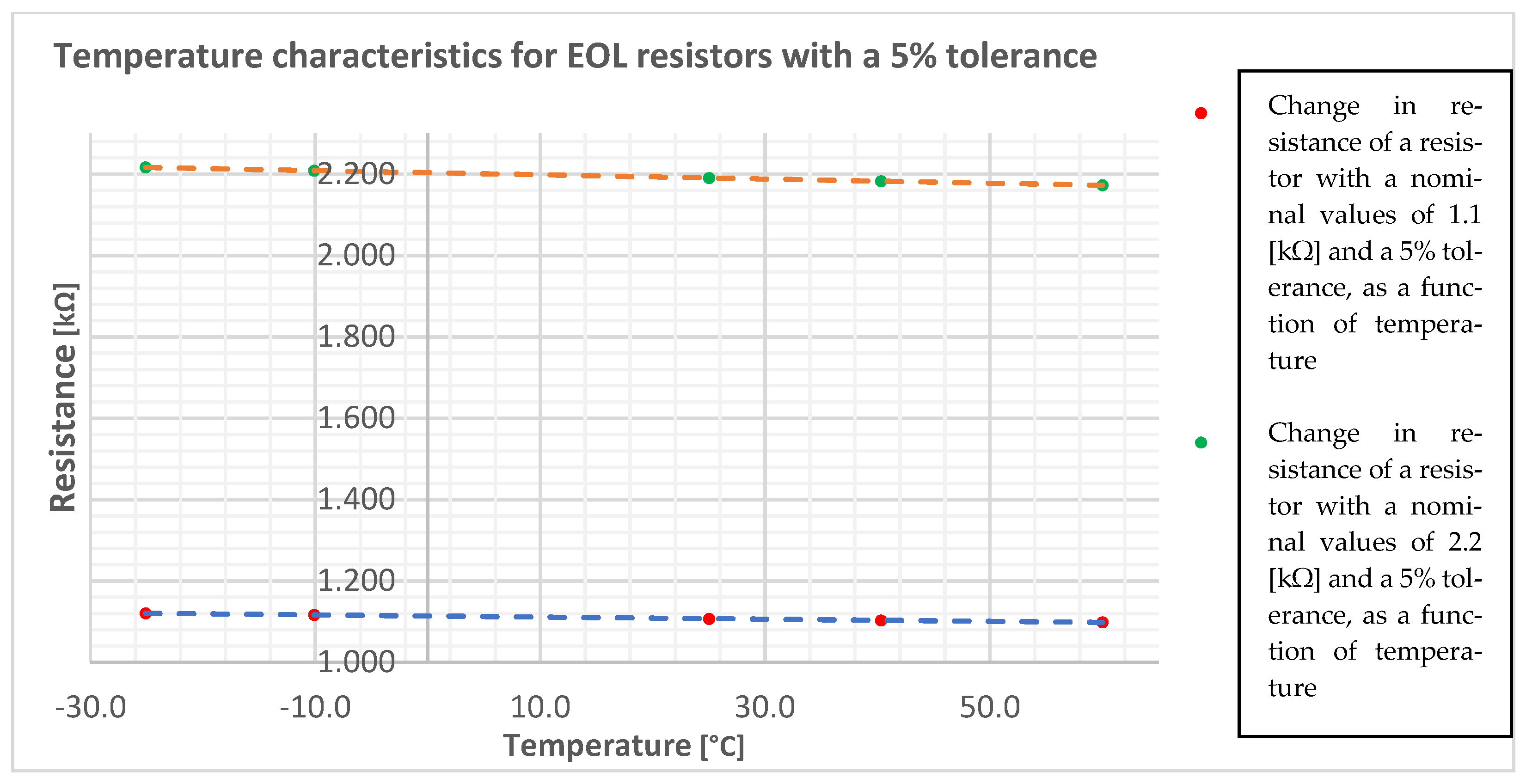
Change in the resistance of a resistor with a nominal value of 1.1 [kΩ] and a 5% tolerance, as a function of temperature
Resistance [kΩ]1.09851.10341.10751.11681.1207
Temperature [°C]60.040.325.0−10.1−25.1
Change of resistance from Tmin. to Tmax. [kΩ]0.0222
Change of resistance from 25.1 [°C] to 60.0 [°C]0.0090
Change of resistance from 25.0 [°C] to −25.1 [°C]0.0132
Change in the resistance of a resistor with a nominal value of 2.2 [kΩ] and a 5% tolerance, as a function of temperature
Resistance [kΩ]2.17302.18252.19062.20892.2167
Temperature [°C]60.040.325.0−10.1−25.1
Change of resistance from Tmin. to Tmax. [kΩ]0.0437
Change of resistance from 25.1 [°C] to 60.0 [°C]0.0176
Change of resistance from 25.0 [°C] to −25.1 [°C]0.0261
Table 2. Permissible ranges of the resistance reached by real resistors with the nominal values of 1.1 [kΩ] and 2.2 [kΩ], at a manufacturing spread of 5%.
Change in the resistance of a resistor with a nominal value of 1.1 [kΩ] resulting from manufacturing spreadRmin. [Ω]Rmax. [Ω]
10451155
Change in the resistance of a resistor with a nominal value of 2.2 [kΩ] resulting from manufacturing spreadRmin. [Ω]Rmax. [Ω]
20902310
Table 3. Permissible ranges of the resistance achieved by real EOL resistors, taking into account the superposition of most unfavorable circumstances.
Resistor with a nominal value of 1.1 [kΩ]
Minimum and maximum resistance resulting from the minimum and maximum superpositions of manufacturing spread resistance and resistance changes at a minimum and maximum temperature1.03181.1640
Resistor with a nominal value of 2.2 [kΩ]
Minimum and maximum resistance resulting from the minimum and maximum superpositions of manufacturing spread resistance and resistance changes at a minimum and maximum temperature2.06392.3276
Table 4. Resistance measurement results for intrusion detection system threshold tripping limits, as a function of temperature.
Temperature: 60.0 [°C]Temperature: 40.2 ± 0.1 [°C]Temperature: 25.0 ± 0.2 [°C]Temperature: −25.1 ± 0.1 [°C]
Resistance [kΩ]Parametric Line StateResistance [kΩ]Parametric Line StateResistance [kΩ]Parametric Line StateResistance [kΩ]Parametric Line State
2.8547A, A, A, A2.8549A, A, A, A2.8549A, A, A, A2.8554A, A, A, A
2.8535A, A, A, A2.8534A, A, A, A2.8533A, A, A, A2.8533A, A, A, A
2.8524A, A, A, A2.8525A, A, A, A2.8528A, A, A, A2.8528A, A, A, A
2.8512A, A, A, NA2.8515A, A, A, A2.8516A, A, A, A2.8514A, A, A, A
2.8496A, A, NA, A2.8498A, A, A, A2.8503A, A, A, A2.8501A, A, A, A
2.8485A, A, A, A2.8484A, A, A, A2.8484A, A, A, A2.8486A, A, A, A
2.8471A, NA, NA, NA2.8472A, A, A, A2.8476A, A, A, A2.8476A, A, A, A
2.8457A, NA, NA, A2.8459A, A, A, A2.8463A, A, A, A2.8462A, A, A, A
2.8444NA, NA, NA, NA2.8446A, A, A, A2.8449A, A, A, A2.8449A, A, A, A
2.8432NA, NA, NA, NA2.8435A, A, A, A2.8436A, NA, A, A2.8436A, A, A, A
2.8418NA, NA, NA, NA2.8421NA, A, A, NA2.8423A, A, A, A2.8422A, A, A, A
2.8406NA, NA, NA, NA2.8408A, NA, NA, NA2.8410A, A, A, A2.8409A, A, A, A
2.8391NA, NA, NA, NA2.8394NA, NA, NA, NA2.8391A, A, NA, A2.8396A, A, A, A
2.8379NA, NA, NA, NA2.8379NA, NA, NA, NA2.8383NA, NA, NA, NA2.8383A, A, A, A
2.8369NA, NA, NA, NA2.8368NA, NA, NA, NA2.8369NA, A, NA, NA2.8369A, A, A, A
2.8352NA, NA, NA, NA2.8355NA, NA, NA, NA2.8357NA, NA, NA, NA2.8356A, A, A, A
2.8339NA, NA, NA, NA2.8341NA, NA, NA, NA2.8343NA, NA, NA, NA2.8342NA, A, A, A
2.8326NA, NA, NA, NA2.8329NA, NA, NA, NA2.8330NA, NA, NA, NA2.8330A, NA, A, NA
2.8313NA, NA, NA, NA2.8316NA, NA, NA, NA2.8317NA, NA, NA, NA2.8317A, A, NA, NA
2.8301NA, NA, NA, NA2.8303NA, NA, NA, NA2.8304NA, NA, NA, NA2.8305NA, NA, NA, NA
2.8286NA, NA, NA, NA2.8282NA, NA, NA, NA2.8285NA, NA, NA, NA2.8290NA, NA, NA, NA
2.8274NA, NA, NA, NA2.8277NA, NA, NA, NA2.8279NA, NA, NA, NA2.8278NA, NA, NA, NA
2.8261NA, NA, NA, NA2.8263NA, NA, NA, NA2.8264NA, NA, NA, NA2.8264NA, NA, NA, NA
2.8248NA, NA, NA, NA2.8246NA, NA, NA, NA2.8245NA, NA, NA, NA2.8237NA, NA, NA, NA
2.2NA, NA, NA, NA2.2NA, NA, NA, NA2.2NA, NA, NA, NA2.2NA, NA, NA, NA
1.5395NA, NA, NA, NA1.5397NA, NA, NA, NA1.5398NA, NA, NA, NA1.5397NA, NA, NA, NA
1.5383NA, NA, NA, NA1.5384NA, NA, NA, NA1.5386NA, NA, NA, NA1.5385NA, NA, NA, NA
1.5370NA, NA, NA, NA1.5371NA, NA, NA, NA1.5372NA, NA, NA, NA1.5372NA, NA, NA, NA
1.5358NA, NA, NA, NA1.5359NA, NA, NA, NA1.5360NA, NA, NA, NA1.5359NA, NA, NA, NA
1.5343NA, NA, NA, NA1.5345NA, NA, NA, NA1.5345NA, NA, NA, NA1.5345NA, NA, NA, NA
1.5330NA, NA, NA, NA1.5332NA, NA, NA, NA1.5333NA, NA, NA, NA1.5333NA, NA, NA, NA
1.5317NA, NA, NA, NA1.5319NA, NA, NA, NA1.5320NA, NA, NA, NA1.5320NA, NA, NA, NA
1.5303NA, NA, NA, NA1.5306NA, NA, NA, NA1.5307NA, NA, NA, NA1.5307NA, NA, NA, NA
1.5292NA, A, NA, A1.5293NA, NA, NA, NA1.5294NA, NA, NA, NA1.5294NA, NA, NA, NA
1.5280A, A, A, A1.5280NA, NA, NA, NA1.5281NA, NA, NA, NA1.5281NA, NA, NA, NA
1.5278NA, A, A, A1.5279NA, NA, NA, NA1.5280NA, NA, NA, NA1.5280NA, NA, NA, NA
1.5266A, A, A, A1.5267A, A, A, NA1.5267NA, NA, NA, NA1.5267NA, NA, NA, NA
1.5251A, A, A, A1.5255A, A, A, A1.5255NA, NA, NA, A1.5255NA, NA, NA, NA
1.5239A, A, A, A1.5241A, A, A, A1.5241A, A, A, A1.5241A, A, A, A
1.5226A, A, A, A1.5229A, A, A, A1.5229A, A, A, NA1.5228A, A, A, A
1.5214A, A, A, A1.5215A, A, A, A1.5216A, A, A, A1.5214A, A, A, A
1.5202A, A, A, A1.5203A, A, A, A1.5203A, A, A, A1.5202A, A, A, A
1.5188A, A, A, A1.5189A, A, A, A1.5189A, A, A, A1.5189A, A, A, A
1.5177A, A, A, A1.5177A, A, A, A
Marking in the Table 4: A-Alarm, NA-No Alarm.
Publisher’s Note: MDPI stays neutral with regard to jurisdictional claims in published maps and institutional affiliations.

