Abstract
This paper presents a detailed analysis and design guidelines for advanced nonoverlapping winding induction machines (AIMs) with coil-pitch of two slot-pitches by considering some vital empirical rules and flux-weakening characteristics. The aim of the study is to develop a type of new winding and stator topology for induction machines (IMs) that will lead to a decrease in total axial length without sacrificing torque, power, and efficiency. The key performance characteristics of the improved AIMs are investigated by 2D time-stepping finite element analysis (FEA) and compared with those of IMs having fractional and conventional overlapping and nonoverlapping windings. Compared with the conventional overlapping winding counterpart of the AIM, a ~25% shorter axial length without sacrificing torque, output power, and efficiency is achieved. In addition, the influences of major design parameters, such as stator slot, rotor slot and pole numbers, stack length, number of turns per phase, machine geometric parameters, etc., on the flux-weakening characteristics are investigated. It has been concluded that the major design parameters have a considerable effect on the electromagnetic performance. However, among those parameters, the influences of pole number and stack length together with the number of turns on flux-weakening characteristics are significant.
1. Introduction
In an effort to improve public health and prevent climate change, the global restricted emissions of CO2 for new passengers’ cars, controlled by the International Council on Clean Transportation, are increasing every year [1]. Thus, the emphasis on automotive electrification has increased considerably in the previous decade to improve the environmental performance and energy efficiency of transportation. Since electrical machines are the core of electric vehicle (EV) propulsion systems, their advancement, combined with power electronics and energy storage devices have garnered considerable attention. In conventional electrical machines, the windings are arranged to achieve maximum fundamental winding factor to maximize the torque.
However, fractional slot concentrated windings (FSCWs) and conventional short-pitch windings with 2 or 3 slot-pitches have significant MMF harmonics resulting in a rise in various parasitic effects such as eddy current [2,3,4,5], bar losses (in induction machines (IMs) and machines with damper windings) [5,6], torque ripple, acoustic noise and vibration [2,3,4,5,6]. In addition, in the previous publication [5] by the authors of this paper, the influence of different winding arrangements having short- and long-pitch windings on the performance characteristics of squirrel cage IMs has been investigated in detail, and it has been concluded that even short-pitch windings, i.e., , are not good enough for electric vehicle/hybrid electric vehicle (EV/HEV) applications in terms of volume, power density, and efficiency.
To reduce or eliminate the undesirable impacts of the magnetomotive force (MMF) harmonics on alternative current (AC) machines, a series of alternative solutions such as multi-layer windings [7,8,9,10,11], dual stator constructions or dual-layer windings [7,12], hybrid star-delta connections [13,14], flux repeller (conductive solid bar that reduces the leakage flux) in the rotor/stator slot openings [15], different numbers of turns per coil side [16], and the recently investigated 2 slot-pitch fractional winding topologies [7,17,18] were developed.
It has been demonstrated that to use multi-layer windings instead of single-layer windings may suppress the torque ripple and bar copper loss and reduce the average torque slightly [6,7]. In addition, it is shown that although the multi-layer windings have no effect on the amplitudes of the MMF super-harmonics, they may cause a significant reduction in the amplitudes of sub-harmonics [9]. Furthermore, the similar result has been addressed by using flux barriers and different numbers of turns per coil sides [16]. The results of these research are, however, not very satisfactory. Hybrid Wye-Delta phase connection technique, requiring three additional phase windings according conventional 3-phase windings, has also been examined as another method to reduce the MMF harmonics. It has been concluded that only the amplitudes of some low-order harmonics have been reduced via this technique [19].
To be able to mitigate or eliminate some MMF harmonics induced in the rotor windings, a double-fed (wound-rotor) IM with multi-layer FSCWs is introduced in Reference [20]. In order to improve the performance of the IMs with FSCWs, some other different methods, such as single- and multi-phase FSCWs [19,21], outer-rotor topology with modular stator windings [22], outer rotor IM with multi-layer FSCWs wound around two and three layers of stator slots [10], multi-layer toroidal windings [8,11], stator cage windings [17], combination of different numbers of turns per one coil side and combined star-delta phase connection [16], and two sets of FSCWs with a dual slot-layer stator structure [23] have been investigated in the last decade. However, although the MMF harmonics are relatively reduced using different above-mentioned methods, new drawbacks, such as low torque-per-flux due to the relatively low-winding factor and increased total axial length and consequently increased copper loss due to the requirement of the additional number of turns have been arisen. Moreover, to improve some performance characteristics, such as slot fill factor, fault tolerant, and simplicity, etc., FSCW technique is utilized for linear IMs, and some feasible MMF reduction methods such as multi-layer modular/planar windings, dual stator structure, etc. have been examined in References [24,25].
In Reference [17], the stator cage winding technique, consisting of solid cage windings whose one-end side has been short-circuited and the other end-side is implemented in an IM, it has been reported that the number of stator slots can be doubled to reduce the MMF sub- and super-harmonics, simultaneously. However, the fundamental harmonic winding factor and hence the output torque reduces when compared to the integer-slot distributed winding (ISDW) counterpart. Moreover, in recently published papers, it has been demonstrated that winding factor and performance improvement of IMs can also be achieved by implementing ring windings [26], pole-changing windings [27], and auxiliary windings [28].
The closer the winding slot pitch to the pole pitch, the higher the fundamental winding factor and the lower the MMF harmonics have been reported in Reference [8]. It is concluded in Reference [8] that in terms of lower parasitic effects and rotor power losses, stator slot/pole/phase number combinations are the best for squirrel cage IMs. The increase in the slot pitch number will cause an increase in the length of end-windings and hence the total axial length, resulting in an increase in the level of stator copper loss. Since the space left for the electrical machines in EVs, especially in HEV applications, is very limited, compactness is a crucial issue. A new methodology should therefore be improved to increase the winding slot pitch number without increasing the end-winding length of the stator windings.
In this study, it is intended to adopt the winding topology proposed in Reference [29] for high-temperature superconductor synchronous machine into an advanced nonoverlapping winding IM (AIM). In Reference [29], it is exposed that the MMF harmonic content of the double-layer nonoverlapping windings is low. Adaptation of this winding topology and development of the new stator structure for more compact IMs is introduced. A new method, consisting of a combination of the phase shift and auxiliary stator teeth methods, has been developed to improve the performance characteristics of IMs. Furthermore, the unfilled stator slots are utilized to reduce the levels of saturation and leakage flux. The performance improvement steps are elaborated, and a detailed performance comparison of IMs designed with the proposed advanced nonoverlapping windings (ANWs), FSCWs, and ISDWs with short- and long-pitch windings are presented. Moreover, the influences of the major design parameters on the steady-state electromagnetic and flux-weakening performance characteristics are investigated by FEA.
The paper is organized as follows. The theoretical background, structure and key properties of conventional and proposed winding topologies are presented in Section 2. In Section 3, performance improvement method and performance comparison of IMs having different winding arrangements are presented. Section 4 deals with the influence of design parameters on steady-state and flux-weakening characteristics of AIM. Some discussion on the validation of FEA results and the key findings of the study and the conclusion are presented in Section 5 and Section 6, respectively.
2. Proposed Advanced Nonoverlapping Windings (ANW) Method
2.1. Theoretical Backgroun of the Proposed Winding Topology
As stated previously, reducing the end-winding length without deteriorating the performance is of great importance in every way. In order to overcome overhanging end-windings of ISDWs, one of the best ways is to change the overlapping winding structure into the nonoverlapping structure.
Consequently, to accomplish the aforementioned objective, an advanced topology with nonoverlapping winding technique, whose basic schematic is shown in Figure 1, has been developed. In essence, the proposed topology shows quite similar characteristics in terms of winding arrangement and consequently winding factor and MMF harmonics with 2-slot pitch overlapping winding. However, it has quite short end-winding lengths thanks to the proposed ANW arrangement. For more details on how to achieve the aforementioned winding structure, see Section 2.3.
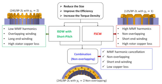
Figure 1.
Schematic of the proposed winding improvement method.
2.2. Conventional Phase Shifting Method
The FSCWs are characterized by a high MMF harmonic content due to the unity slot pitch number and fractional number of slots per pole per phase [3,6] and the multi-layer winding method is extensively used to reduce or eliminate these unwanted harmonics [7,8,9]. In this part, to reveal the influence of phase shifting method on the winding harmonic factors and averaged torque, torque ripple, and rotor bar copper loss characteristics, IM having FSCWs with 9S/6P-DL () will be studied. The winding arrangement and phase shifting method are illustrated in Figure 2. Each slot has 4-layers windings and the 1st set (bottom layer) is selected as reference (fixed) frame while the 2nd set of winding is selected as to be shifted frame. Since there are 9 slots in the stator, the shifting angle is calculated as e (electrical degree) per slot. The polarities of all windings are initially set as positive (), and they are fixed throughout the end of the shifting progress. After 1080°e of the shift angle is completed, the polarity of the second set of winding has been changed from positive () to negative (), and the shifting process is re-started. Consequently, the variations of key performance characteristics obtained from the above-mentioned phase shifting process are observed as follows. Note that the key design specifications of studied IMs are given in Appendix A—Table A1.
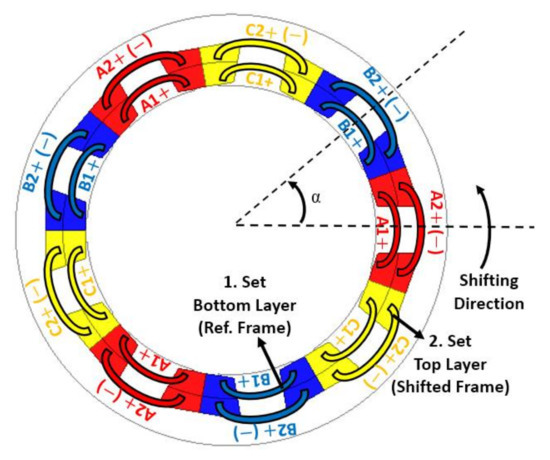
Figure 2.
Winding layout of the 9S/6P-4L: () is the base polarity and () is the opposite polarity.
The new winding factor , which is subjected to the initial winding factor, the harmonic order, the shift angle in e, and the pole number , can be calculated by Equation (1). The variation in the low- and high-order winding harmonic factors with is shown in Figure 3. Since the winding harmonic factors of the 9S/6P combination have only sequential harmonics, whose amplitudes are 0.866, many of the harmonics vary with the same pattern, i.e., the first group 3rd, 15th, 21st and the second group 6th, 12nd, and 24th harmonics have the same pattern. The same phenomenon is valid for the higher-order harmonics. Alternatively, even if the direction of the 2nd winding set becomes negative (), the same waveform shown in Figure 4b is obtained.
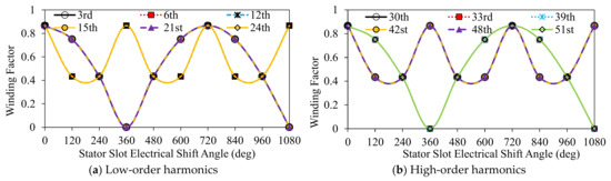
Figure 3.
Variation of winding harmonics with : (a) low-order and (b) high-order.
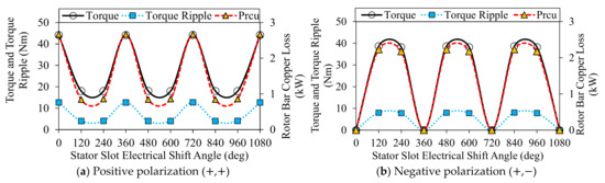
Figure 4.
Variation of torque, torque ripple and rotor bar copper loss with : (a) while the both of the winding sets are in () polarization and (b) while the 1.set is in () and 2.set is in () polarization.
As shown for both cases (,) and (,), the rotor bar copper loss, torque and torque ripple have the similar waveform (see Figure 4). Considering Figure 3, it can be deduced that the working winding harmonic is shifted from 3rd to 6th. That is why the torque is maximized at 360°e. Once the polarity of 2nd set of winding is alternated from () to (), the obtained performance characteristics are shown in Figure 4b. As seen in Figure 4b, because changing the winding polarization causes the formation of dead-slots, the zero-torque values are obtained at 0°e, 360°e, 720°e, and 1080°e of the shift angle. Furthermore, changing the direction of windings results in a slight reduction in the average torque, torque ripple, and rotor bar copper loss. Considering the obtained results in this part, it can be concluded that the winding harmonics cannot be cancelled or mitigated sufficiently. Consequently, it is revealed that reduction of the MMF harmonic content of the 9S/6P combination is not possible by the conventional phase shifting method.
2.3. Phase Shifting with Auxiliary Teeth Method
In this part, an advanced phase shifting method to reduce the MMF harmonics is proposed. In order to provide an extra shifting angle which may cause a reduction in the MMF harmonic content, the stator slot number of the 9S/6P-4L combination has been doubled. As a result of the stator slot number being doubled, became e per slot. The winding layout and shifting scheme of the new combination are shown in Figure 5. Since the windings do not physically overlap each other, each coil can be considered as a single lap-coil as in the FSCW topology even if . With this technique, lap-coil windings can therefore be designed with a range of slot pitches without reducing the fundamental winding factor. However, this method cannot be utilized for each S/P combination. There are certain rules for appropriate combinations as defined in Equations (2) and (3). To utilize the lap-coils with multiple overlays (), Equation (3) should be satisfied. In Equation (3), is a positive integer and indicates the fundamental winding factor of any combination with pole-pair number and indicates the greatest common divisor of S and P. For this type of windings, is consistently equal to and the fundamental harmonic of the winding factor needs to be different from unity. On the other hand, Equation (4) can be used for combinations. The same phase shifting method, detailed in the previous part, has been utilized for the 2x9S/6P with the halved shift angle.
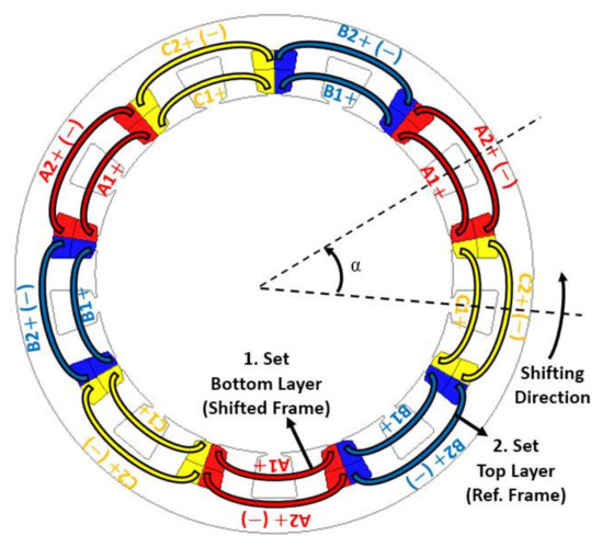
Figure 5.
Winding layout of 2x9S/6P-4L combination.
Once the winding directions are (+,+), variation of the winding harmonic factors with is shown in Figure 6. It is deduced that compared to the 9S/6P, adding auxiliary teeth leads further reduction of the winding harmonics. Depending on , some of the low- and high-order harmonics have been reduced and some have completely been eliminated i.e., 6th, 30th, 42nd, 63rd, and so on harmonics are cancelled at the 180°e. But, the fundamental winding factor has decreased at this shift angle. Once the winding directions are (,), the variation of the winding harmonic factors with shift angle is shown in Figure 7. By adopting the negative polarity of the 2nd set of windings, the 6th and all the multiples of the 6th harmonics are eliminated at 180°e. In addition, the fundamental winding factor is maximized at 180°e and hence the optimum shifting angle is found as 180°e for 2x9S/6P combination. After shifting 180°e (3 slot-pitches) of the 2nd winding set and assigning the correct polarizations, the final winding arrangement of the 2x9S/6P is illustrated in Figure 8.
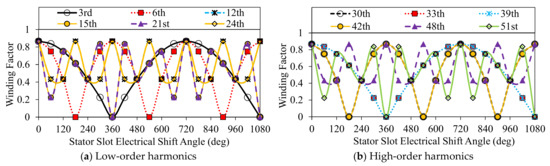
Figure 6.
Variation of low-order (a) and high-order (b) harmonics with respect to shift angle while the winding set polarizations are (,).
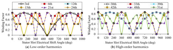
Figure 7.
Variation of low-order (a) and high-order (b) harmonics with respect to shift angle while the winding set polarizations are (,).
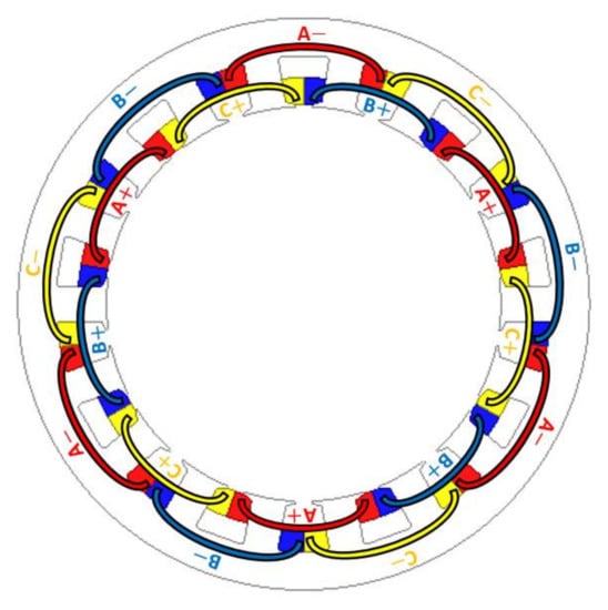
Figure 8.
Final winding layout for 2x9S/6P combination.
As a natural consequence of the proposed phase shifting technique, the half of each slot remains unfilled. Nevertheless, these unfilled slots will be utilized, and its influence on the performance characteristics will be investigated in Section 3. An index has been defined as expressed in Equation (5) to determine the distortion level of the winding factor.
As shown in the comparison of initial and final winding harmonic factors and calculated harmonic interaction indices (see Figure 9), the winding harmonics are significantly reduced, particularly at 180°e shifting angle, whereas the winding sets are polarized as (,). It may therefore be predicted that the rotor bar copper loss of 2x9S/6P combination will be substantially low in comparison to the 9S/6P combination. Moreover, since the magnitude of the fundamental winding factor has not changed, no average torque will be sacrificed. Variations of time-averaged torque, torque ripple, and rotor bar copper loss with are shown in Figure 10 for both of the winding set polarizations. Figure 10b reveals that by doubling the stator slot number and arranging the winding polarizations as (,), a more than 50% reduction in rotor bar copper loss can be achieved. In addition, a slight reduction in torque ripple at maximum torque is also achieved. The amount of rotor bar copper loss may be predicted by observing the winding factor harmonics. For 2x9S/6P combination, the dominant harmonics causing an increase in the bar copper loss are revealed as listed in Table 1. Note that the results listed in Table 1 are obtained from the shifting angles delivering the maximum torque. From Table 1, it can be observed that if the 6th or/and 12th harmonics are eliminated, the reduction in the amount of bar copper loss will be substantial.
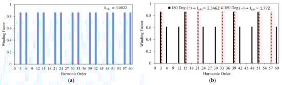
Figure 9.
Comparison of winding factors: (a) initial (original) and (b) final winding factors after the phase-shifting operation.
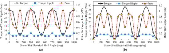
Figure 10.
Variation of torque, torque ripple, and rotor bar copper loss with shift angle : (a) while the both winding sets are in positive polarization (,) and (b) while the 1.set is in positive and 2.set is in negative polarization (,).

Table 1.
Normalized performance characteristic comparisons.
It has been found that if the 6th harmonic is eliminated, the bar copper loss decreases by ~2.5 times, or if the 6th and 12th harmonics are eliminated simultaneously, the rotor bar copper loss decreases by ~6 times. Hence, it can be predicted that the reduction or elimination of low order harmonics has a major impact on the rotor bar copper loss. The decrease in the amplitudes of these harmonics also causes the torque ripple to reduce. On the other hand, once the slot number is doubled, the average torque drops. The underlying reason might be explained for 2x9S/6P (,) and 2x9S/6P (,), separately. For the 2x9S/6P (,), the saturation level increases because of the doubled stator slots, and it causes a decrease in torque. Yet, for the 2x9S/6P (,), in addition to the increase in the saturation level, the fundamental winding factor decreases slightly due to the phase shifting (see Figure 9b).
3. Performance Improvement of AIMs
After the phase-shifting operation, half of each stator slot has been left unfilled in order to prevent overlapping the phase windings as seen in Figure 11a. These incompletely filled slots cause an increase in the saturation level of the stator teeth parts (see Figure 12). On the other hand, partially filled slots are useful in terms of thermal issues, i.e., they help to reduce the temperature inside the slot, leading to more overloading of the machine. By utilizing these partially filled slots as illustrated in Figure 11b, some performance characteristics of the IM can be further improved. The development phases of the stator slots are illustrated in Figure 11. The main advantage of the proposed method is that it leads to a reduction in the total axial length of the machine without sacrificing the winding factor, and hence the torque and power density.
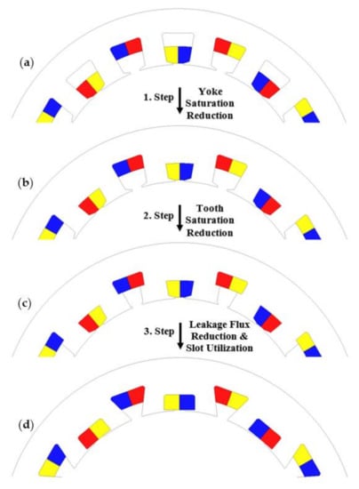
Figure 11.
Improvement sequence of AIM. (a) Yoke saturation reduction; (b) tooth saturation reduction; (c) leakage flux reduction and slot utilization; (d) final configuration.
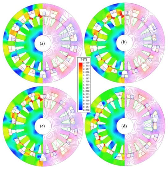
Figure 12.
Flux density and line distributions of the AIMs. (a) 1. Step; (b) 2. Step; (c) 3. Step; (d) final configuration.
3.1. Improvement by Utilizing the Stator Slots
It is intended to improve the magnetic characteristics, such as electromagnetic circuit, saturation level, flux leakage, etc. by reshaping the stator slots. By utilizing slots with the sequence shown in Figure 11, the saturation level of the stator yoke and tooth parts are reduced noticeably as seen in Figure 12. From the flux line and flux density distributions corresponding to each step, shown in Figure 12, the reduction of saturation levels can be easily observed. A reduction in yoke and stator tooth saturation, and a further reduction in tooth saturation by avoiding the short-circuited flux, have been achieved from a to b, b to c, and c to d, respectively.
The influence of each performance improvement step on the performance characteristics has been numerically calculated and compared as illustrated in Figure 13. The same geometric (144mm outer diameter, 0.35 mm air-gap length, and 70 mm average stack length) and operational parameters (48 Vrms inverter voltage, 500 Arms excitation current and 2 krpm synchronous speed) have been assigned for a fair comparison (see other major specifications given in Appendix A—Table A1). Note that since the key geometrical and operating specifications, including the rated power levels and pole numbers, are the same, all IMs are designed with the same air-gap length. As seen in Figure 13, the time-averaged torque is increased remarkably from the initial (a) to the final design (d). Moreover, although the time-averaged torque is increased by ~19%, the torque ripple percentage is kept constant.
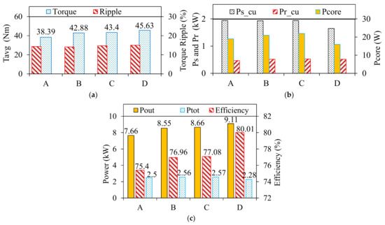
Figure 13.
Electromagnetic performance comparison: (a) average torque and torque ripple; (b) power losses , , and ; and (c) output power , total loss , and efficiency.
The major power losses including the stator copper loss Pscu, rotor bar copper loss Prcu, and total iron core loss Pc have been compared in Figure 13b. Thanks to the proposed method, Pscu and Pc decreased by 15% and ~28%, respectively. Comparison of the total power loss Ptot, output power Pout, and efficiency are shown in Figure 13c. Since Pout is increased by ~19%, whilst Ptot is decreased by 8.8%, the efficiency is increased by 7.3%, consequently.
As a result, the key performance characteristics of the AIM have been improved significantly thanks to developed method, which allows better slot utilization. Although there still some partially filled slots left consistently in the stator, they can help the short-circuited flux to be reduced and, also, the thermal characteristics of the AIM to be improved for much heavy overloading operations.
3.2. Comparison between FSCW, ANW, and ISDW IMs with Short and Long Slot-Pitches
In order to reveal the merits and demerits of the proposed method, the characteristics of IMs having FSCWs and ISDWs with short- and long-slot pitches have been compared to those of the ANW topology.
For a fair comparison, the improved AIM (indicated as “D” in the previous subsection) and the other machines have been optimized globally by using the multi-objective optimization method presented in Reference [30]. All IMs are designed by using the same geometry specifications specified in Appendix A—Table A1, and their 2D cross-sectional views together with the numbers of turns per phase are illustrated in Figure 14. The winding arrangement of (a) and (b) consists of nonoverlapping double-layer windings, while (c) and (d) consist of overlapping double-layer windings. In fact, the topology (c) is the overlapped winding version of the topology (b). In terms of , (a) belongs to the FSCW family, whereas the others belong to the ISDW family. In addition, it is worth noting that, in terms of winding slot pitches, winding polarizations, and hence, winding harmonic factors, the 18S/6P/20R-DL () is the overlapping version of the 18S/6P/20R-DL (ANW).
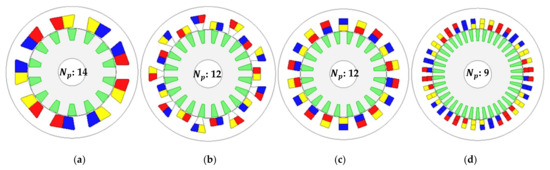
Figure 14.
Two-dimensional views of IMs designed with FSCW, ANW, and ISDW topologies. (a) 9S/6P/14R-DL (); (b) 18S/6P/20R-DL (ANW); (c) 18S/6P/20R-DL (); (d) 36S/6P/38R-DL ().
The optimal rotor slot numbers have been estimated by and some basic rules used to avoid excessive torque ripple, unbalanced magnetic force, etc. The details related to this subject can be found in Section 4 and References [31,32,33,34,35].
Induced voltage waveforms for stator phase “A” winding are illustrated in Figure 15a. Since the 9S/6P IM has the greatest , its induced voltage amplitude is the highest, as seen in Figure 15b. However, the 9S/6P IM’s waveform contains a large number of high-frequency harmonics with high amplitudes as a consequence of the combined effect of slotting and a highly distorted MMF waveform. Thus, its induced voltage THD is larger than that of the other IMs. The same phenomenon is valid for other electromagnetic characteristics, such as the air gap flux density and bar current, as shown in Figure 16 and Figure 17, respectively. Note that, in order to calculate the bar current waveforms with high accuracy, the skin effect is taken into account by the FEA. In addition, all the FEA results were obtained under steady-state operating conditions at the pull-out torque slip.
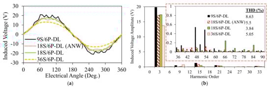
Figure 15.
Induced voltage in phase ‘A’: (a) waveforms and (b) harmonic spectra.
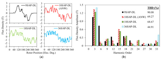
Figure 16.
Air gap flux density: (a) waveforms and (b) harmonic spectra.
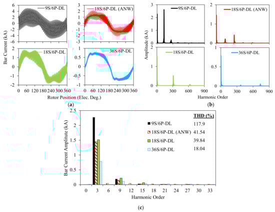
Figure 17.
Rotor bar current: (a) waveforms, (b) harmonic spectra, and (c) low-order harmonics.
Even if the 9S/6P IM has the highest , due to the increased saturation level of the stator teeth (see Figure 18), the magnitude of the air gap flux density is lower than those of other IMs, as seen in Figure 16b. On the other hand, since the space harmonic index of 36S/6P is the lowest, the distortion level of maximum and minimum for the bar current waveforms of 9S/6P FSCW and 36S/6P ISDW can be predicted, respectively. This is due to the recursive induction phenomenon that occurs on the rotor bars: the air gap flux density induces a voltage in the rotor bars, and hence, the bar current occurs due to the short-circuited conductor bars. As seen in Figure 17a, the waveforms of the 18S/6P and 36S/6P IMs seem to be trapezoidal or flat-tapped. Under the health operation conditions, the bar current waveform of an IM is usually assumed to be sinusoidal. Yet, as seen in the figures, the obtained bar current waveforms are non-sinusoidal. The underlying reasons of this phenomenon have been expiated in detail in References [5,31,32,33,34,35].
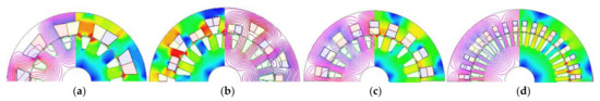
Figure 18.
Flux line and density distributions. (a) 9S/6P/14R-DL; (b) 18S/6P/20R-DL (ANW); (c) 18S/6P/20R-DL; (d) 36S/6P/38R-DL.
The resistance and leakage reactance have been calculated and presented in Table 2. Note that the subscripts s and r indicate the stator and rotor; indicates the resistance; and , , indicate the leakage reactance values belonging to the slot, end winding, and differential, respectively. Considering Figure 18 and Table 2, it can be concluded that there is a linear correlation between the space harmonics and magnetic saturation and, hence, leakage reactance. The 9S/6P IM has the highest leakage reactance parameters, while the 36S/6P has the lowest. In addition, the IMs with 18S/6P combinations have a medium leakage reactance values compared to the other IMs.
Table 2.
Comparison of the resistance and reactance data at a rated operation.
Other calculated electromagnetic performance characteristics, namely , , , , , , , , , , , , and representing the total axial length, time-averaged torque at pull-out speed, torque ripple, total copper loss in stator slots, total copper loss of end windings, rotor bar copper loss, total core loss, output power, slip, rotor speed, efficiency, and stator and rotor current densities, respectively, are summarized in Table 3. Compared to the 9S/6P/14R IM, the 18S/6P/20R-DL (ANW) IM offers better performance characteristics, particularly in terms of parasitic effects, machine losses, and temperature (current density). It is found that, thanks to the ANW topology, a ~27% reduction in the total axial length has been achieved without sacrificing the torque, power, and efficiency, according to its overlapping counterpart (). On the other hand, 36S/6P/38R IM possesses the best overall performance characteristics because of its the lowest MMF harmonic content, except for the total length. However, 18S/6P/20R-DL (ANW) has the potential to offer better performance characteristics because of its ~25% shorter total length than that of 36S/6P/38R IM. It is worth noting that, considering the very limited space left for electrical machines in HEV applications, since compactness is of great importance, a ~25% reduction in the total axial length would be a great advantage.
Table 3.
Comparison of some parameters and key characteristics.
Having a high torque ripple is the main disadvantage of the proposed topology. However, it can be reduced significantly by changing the rotor slot shape, as will be presented in future works.
4. Comprehensive Design Guidelines for AIMs
As known, the electrical machine performance is heavily dependent on the stator slot number S, pole number P, and rotor slot number R combinations. Determination of the accurate S/P/R combination becomes a very critical issue when there exist very strict restraints on the flux-weakening capability, torque quality, acoustic noise, vibration, and efficiency characteristics. Therefore, determination of the accurate S/P/R combination is crucial for applications such as EV/HEV, aerospace, wind turbines, etc., which require high performances with low parasitic effects.
In this section, useful design guidelines for IMs with ANWs are presented. The influences of the major design parameters on the electromagnetic and flux-weakening performance characteristics are also investigated by FEM. The considered design parameters and their ranges are summarized as follows:
- S/P combination: 18S/6P, 24S/8P, 30S/10P, and 36S/12P;
- Rotor slot number: from 14 to 62;
- Stack length: from 70 mm to 110 mm;
- Number of turns per phase: from 7 to 13;
- Geometric parameter: split ratio, slot and slot opening widths and heights.
In order to maintain the torque in the constant torque region, IMs having higher pole numbers or shorter stack lengths require a greater number of serial turns per phase. Note that the stack lengths considered in this study are the averaged values determined by considering the lamination thickness and stacking factor given in Appendix A—Table A1. In addition, both the rotor and the stator have the same stack lengths. Since there exists a linear correlation between the phase inductance and turns number, an increase in the turns number causes an increase in the terminal voltage requirement, as seen from Equations (6) and (7), where and are the d- and q-axis components of the stator current, and are the d- and q-axis components of the rotor current, is the equivalent stator winding resistance, is the pole pair number, is the equivalent stator winding inductance, and is the mutual inductance between the stator windings and rotor bars or magnetizing inductance.
As seen in Figure 19, the amount of torque depends on the inverter’s current limit, whilst the range of the corner speed (A point in the curve) depends on the voltage limit. Considering the limited voltage output of an inverter driving the IM, increased voltage requirement cannot be met by inverter if it exceeds its maximum value. Therefore, the corner speed of the IM will be moved from a high-speed to a low-speed region in cases of an increased number of turns. Consequently, a poorer flux-weakening performance is inevitable for IMs having a higher pole number or shorter stack lengths.
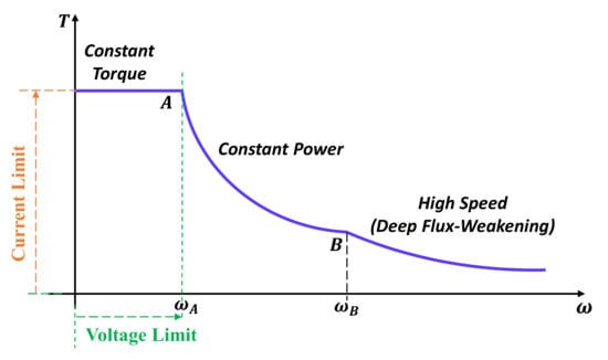
Figure 19.
Torque-speed curve of an IM showing the inverter voltage and current limits.
4.1. Stator Slot and Pole Number Combination
In the previous section and Reference [8], it has been shown that the minimum harmonic interaction index can be achieved in case of for slot-pitch and for winding topologies. For the different combinations that satisfy these conditions, it can be deduced that the higher the stator slot number, the lower harmonic interaction index. It is also worth noting that the higher the pole number, the higher the synchronous frequency requirement and, consequently, the increased core losses at high-speed region. Therefore, a balance between the rotor bar copper loss and total core losses should be established. The flux-weakening characteristic is another critical characteristic that needs to be considered carefully before determining the S/P/R combination. It well-known that the lower the pole number, the better the flux-weakening capability.
The AIMs having different S/R/P numbers with the same geometric and operating specifications were designed, and their flux-weakening characteristics were calculated as shown in Figure 20. As expected, the 6P AIM has the best flux-weakening performance. Moreover, as seen in Figure 20b, there was a big reduction in power once increased from 10 to 12. This is because of the different serial number of turns per phase and, consequently, the different phase inductances. The serial number of turns per phase were 7, 8, 9, and 13 for 6P, 8P, 10P, and 12P, respectively. These turn numbers were parametrically determined to maintain the averaged torque at ~54 Nm in the constant torque region. Although all considered IMs have the same fundamental winding factor, since their saturation levels are different, they require different numbers of turns. In particular, the 12P has the highest saturation level and, consequently, requires more turns to maintain the required torque. Thus, because of the large serial number of turns per phase differences between 10P and 12P IMs, there has been a big reduction in torque and, hence, power. The efficiency maps of the considered AIMs are also calculated and compared in Figure 21. As expected, the 6P, 8P, and 10P IMs have a similar efficiency map, whilst the 12P IM has a worse efficiency map because of the higher power losses, particularly core losses, versus lower output power.
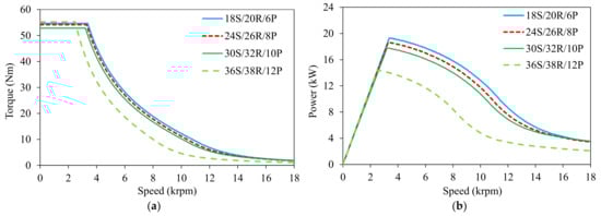
Figure 20.
Flux-weakening performance comparison for 80 mm AIMs designed with different stator slot/rotor slot/pole number combinations: (a) torque-speed curve and (b) power-speed curve.
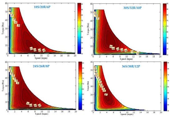
Figure 21.
Efficiency map comparison for 80 mm AIMs designed with different stator slot/rotor slot/pole number combinations.
The essential factors are described as follows in the accurate selection of the S/P combination of the squirrel cage IMs.
- (a)
- Minimized harmonic interaction index for minimum rotor bar copper loss ( for and for combinations);
- (b)
- High pole number for lower rotor bar copper loss;
- (c)
- Demanded torque-speed curve;
- (d)
- Low pole number for higher torque and, hence, power at the constant power region;
- (e)
- Low pole number for lower core losses.
4.2. Rotor Slot Number
The selection of the number of rotor slots R and their geometric parameters are critical in terms of acoustic noise, vibration, torque density and torque ripple, and rotor losses. Some empirical rules were reported in References [34,35,36,37] to determine the optimal rotor slot number of an IM. Based on the conducted parametric analysis in this study, more comprehensive empirical rules to determine R were provided as follows:
- (a)
- To avoid a high torque ripple, acoustic noise, and unbalanced magnetic pull (UMP), R should not be:
- multiples of the phase number () ;
- multiples of the pole number ();
- multiples of the stator slot number ();
- odd numbers.
- (b)
- To avoid the high rotor bar copper loss and bar current density, should be low;
- (c)
- close to the stator slot numbers are good candidates;
- (d)
- In terms of the average torque, torque ripple, bar copper loss, and current density, the optimum can be determined as .
Numerous parametric analyses for AIMs with 18S/6P, 24S/8P, 30S/10P, and 36S/12P combinations were performed in order to reveal the influence of R on the performance and, also, to determine the best rotor slot number. To be able to conduct a reasonable comparison, all parameters were kept constant, and the ratio of rotor slot width to rotor slot pitch was also kept constant (see Equation (8) and Figure 22). Under these analysis conditions, the influence of the rotor slot number on the electromagnetic performance characteristics is investigated as follows.
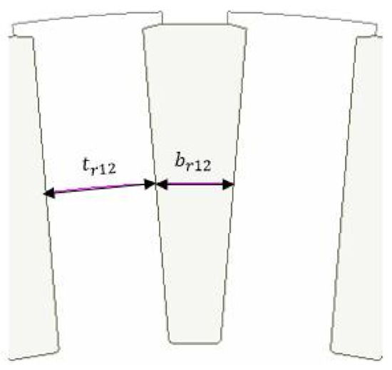
Figure 22.
Rotor geometry.
For the 18S/6P combination, variations of the averaged torque, torque ripple, bar copper loss, and bar current density with the rotor slot number are illustrated in Figure 23. As expected, the torque ripple percentage is tremendously high for multiples of the phase, pole, and stator slot numbers. It was also revealed that the rotor slot number has a trivial effect on the average torque (see Figure 23a). Considering Figure 23a, it can be concluded that the above-mentioned empirical rules for determining the optimal rotor slot number have been validated. In addition, the rotor bar copper loss and bar current density increase excessively as R increases (see Figure 23b). Consequently, the optimal rotor slot number offering the maximum torque with the minimum torque ripple and a relatively low bar copper loss and bar current density for the 18S/6P AIM is determined as 20. In the same manner, the same performance characteristics are calculated for 24S/8P, 30S/10P, and 36S/12P, as illustrated in Figure 24, Figure 25, and Figure 26, respectively. The optimal rotor slot numbers for the 24S/8P, 30S/10P, and 36S/12P AIMs are selected as 26, 32, and 38, respectively.
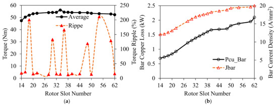
Figure 23.
Influence of the rotor slot number on the performance characteristics of 18S/6P AIM: (a) torque and torque ripple and (b) bar copper loss and bar current density.
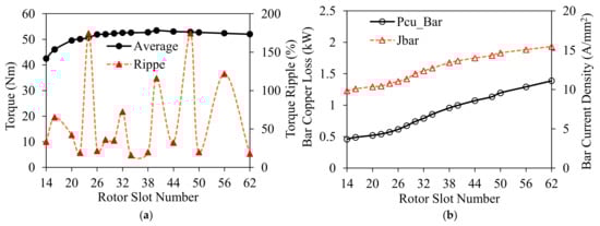
Figure 24.
Influence of the rotor slot number on the performance characteristics of 24S/8P AIM: (a) torque and torque ripple and (b) bar copper loss and bar current density.
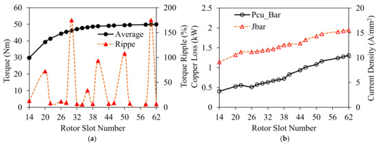
Figure 25.
Influence of the rotor slot number on the performance characteristics of 30S/10P AIM: (a) torque and torque ripple and (b) bar copper loss and bar current density.
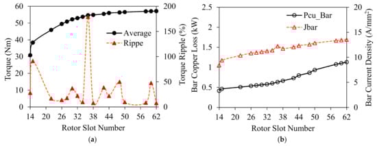
Figure 26.
Influence of rotor slot number on the performance characteristics of 36S/12P AIM: (a) torque and torque ripple and (b) bar copper loss and bar current density.
The parametric analysis results conducted to determine the optimal rotor slot number also showed that increasing the rotor slot number causes an increase in the pull-out torque slip (see Figure 27). Therefore, the low power factor for IMs having higher rotor slot numbers can be predicted. Some other key findings obtained from the analyses are summarized as follows:
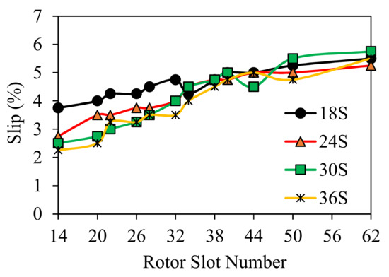
Figure 27.
Variation of the pull-out torque slip with a rotor slot number for various S/P combinations.
- (a)
- The higher the S/P combination, the lower the bar copper loss, current density, and torque ripple;
- (b)
- For combinations , a lower torque is achieved, but for combinations, the torque does not change considerably;
- (c)
- Higher rotor slot numbers result in an increased pull-out torque slip and, hence, lower power factor.
4.3. Stack Length
One of the most critical design parameters of IMs for EV/HEV application is the stack length. Apart from the basic sizing equation (see Equation (9)) [38], where is a coefficient depending on the electric and magnetic loadings and is the outer diameter of the stator, the stack length of an IM can simply be determined by taking into account the number of turns, stator winding current density, and desired flux-weakening characteristics.
In this part, the influences of the stack length together with the constant and variable number of turns on the steady-state and flux-weakening characteristics will be investigated together.
4.3.1. Constant Number of Turns per Phase Case
A scenario to alter the stack length by keeping a number of turns constant for the 36S/12P/38R design with 8, 9, and 13 turns per phase was developed in order to identify the ideal combination of stack length and number of turns. Variations of the averaged torque and efficiency with the stack length for different stator current density values (ranging from 25 A/mm2 to 32 A/mm2) are illustrated in Figure 28 for the above-mentioned number of turns. Considering these figures, some key findings have been summarized as follows. Note that the efficiency percentages are calculated for values only between 54 Nm and 56 Nm.
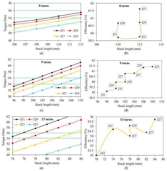
Figure 28.
Variation of torque and efficiency for different current density amounts: (a,b) 8 turns per phase, (c,d) 9 turns per phase, and (e,f) 13 turns per phase.
- (a)
- As expected, there is a linear correlation between the torque and stack length.
- (b)
- For high values of stator current densities and, also, number of turns, it is possible to achieve a higher torque with shorter stack length but lower efficiency.
- (c)
- There is an inverse correlation between the efficiency and current density and, also, efficiency and current density.
- (d)
- Increasing the stack length always helps to improve the electromagnetic performance characteristics.
4.3.2. Variable Number of Turns per Phase Case
The variations of the number of turns per phase () and pull-out torque slips were investigated for the 36S/38R/12P AIM and shown in Figure 29. Note that the parametric analyses were conducted under the pull-out torque condition. As seen, in order to maintain the torque, a lower number of turns was required for a longer stack length. In addition, it has been revealed that a reduction in the slip at the pull-out torque can be achieved with a longer stack length. Thus, a higher power factor and efficiency can be predicted for longer stack lengths.
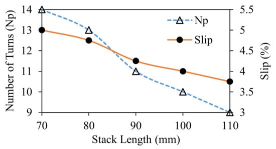
Figure 29.
Variation of number of turns per phase and slip-to-stack length.
The variations of the key performance characteristics as a function of the stack length are illustrated in Figure 30 and Figure 31. It has been revealed that, for the variable number of turns case, there existed an optimum number of turns for a specific stack length, allowing the AIM to provide the maximum torque and power. In addition, it can also be seen that the stator and rotor current densities can be reduced simultaneously with increasing the stack length. Since the number of turns per phase is decreased with the increasing stack length, the total winding resistance and, hence, the stator copper loss decreases with the increasing stack length, and consequently, the efficiency increases. Since the number of turns per phase is decreased with the increasing stack length, the total winding resistance and, hence, the stator copper loss decreases with the increasing stack length, and consequently, the efficiency increases. The steady-state analyses are insufficient to determine the optimal number of turns and stack length parameters. The influence of these parameters on the flux-weakening characteristics should also be investigated for particularly adjustable speed applications, such as EV/HEV.
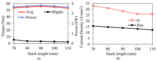
Figure 30.
Variation of some key performance characteristics with the stack length: (a) time-averaged torque, torque ripple, and power and (b) stator and rotor bar current densities.
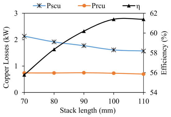
Figure 31.
Variation of copper loss and efficiency with the stack length.
4.3.3. Flux-Weakening Characteristics
In this part, the influence of stack length on the flux-weakening characteristics was investigated. Note that the number of turns was optimized according to the maximum torque at a nominal speed. The torque-speed and power-speed characteristics of the 36S/38R/12P AIM are calculated and illustrated in Figure 32. As can be seen, since AIMs with longer stack lengths require fewer turns, they offer a better flux-weakening performance, particularly at high-speed regions. The reason behind this phenomenon is simply the number of turns corresponding to the phase inductance, as explained previously. It can be deduced that, for applications requiring a high torque at high speeds, the AIMs can be designed to have a longer stack length with a fewer number of turns.
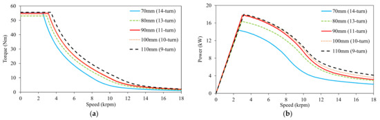
Figure 32.
Flux-weakening characteristics of 36S/38R/12P AIM for various stack lengths and number of turns. (a) Torque-speed curve; (b) power-speed curve.
4.4. Number of Turns
Considering the previous analyses related to the number of turns, it can be deduced that it is one of the other most critical design parameters, having a vital impact on the electromagnetic characteristics. To find out the optimal number of turns, in addition to the S/P combinations, the maximum allowable stator current density, stack length, and flux-weakening characteristics should be considered. Particularly for EV/HEV applications, the desired torque/power–speed characteristics were specified before the preliminary design, and the electrical machines were optimized so as to meet the desired torque/power–speed characteristics.
In this part, 70 mm and 90 mm stack lengths were considered, and all the calculated curves were compared to the specified (Spec.) torque/power-speed curves. Note that the torque and power-speed curves of the AIMs have numerous S/P combinations, and the number of turns is calculated by maintaining the stator current density at 31 A/mm2. In addition, the previously given current and voltage limits were not exceeded during the calculations. The calculated torque/power-speed curves are illustrated in Figure 33 and Figure 34 for 70 mm and 90 mm, respectively. It can be observed from the figures that the AIMs with a lower number of turns offer a higher torque in the high-speed region but low torque in the constant-torque region. In addition, AIMs with longer stack lengths have better field-weakening potential. Moreover, as a natural behavior of a squirrel cage IM, the power in the constant power region decreases more rapidly than those of synchronous machines [39]. In both the 70 mm and 90 mm stack length cases, the 18S/20R/6P combinations with 12 turns and 9 turns, respectively, are the best candidates meeting the specified torque/power-speed characteristics.
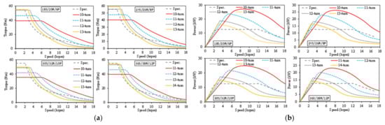
Figure 33.
Flux-weakening characteristics of 70 mm AIMs with different S/P combinations and number of turns: (a) torque-speed and (b) power-speed.
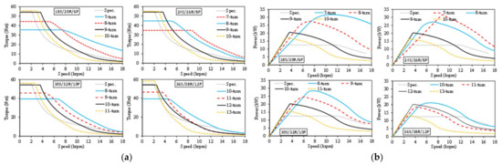
Figure 34.
Flux-weakening characteristics of 90 mm AIMs with different S/P combinations and number of turns: (a) torque-speed and (b) power-speed.
4.5. Stator and Rotor Geometric Parameters
Following the determination of the major specifications, such as the S/P/R combination, number of turns, and stack length, the influences of the key machine geometric parameters on the steady-state electromagnetic performance characteristics were investigated. In this part, the individual influence of each parameter, indicated in Figure 34, was parametrically analyzed for 36S/38R/12P AIM with a 110 mm stack length. Note that the operating conditions, stator outer diameter, and air gap length parameters were kept constant during the analyses (see Appendix A—Table A1 for the other specifications).
The definitions of the geometric parameters, illustrated in Figure 35, are given as follows. is the split ratio, identified as the ratio of the stator inner diameter to the stator outer diameter as given in Equation (10). The stator slot width, and, as expressed in Equation (11), is a function of since the slot fill factor is kept constant for all the stator slots. Furthermore, since the winding topology is a nonoverlapping type, a ratio between the top and bottom layers, viz, stator slot heights, is defined as given in Equation (12). Moreover, since the rotor teeth are designed to have parallel shapes, the rotor slot parameters are correlated to each other as expressed in Equation (13).
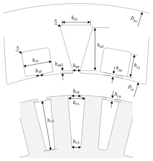
Figure 35.
Stator slot and rotor geometry parameters.
4.5.1. Split Ratio
The influence of the split ratio on the averaged torque and torque ripple is shown in Figure 36. The maximum torque at the pull-out slip is obtained at 0.753. In addition, it can be deduced that the split ratio has a trivial effect on the torque ripple within the selected split ratio range.
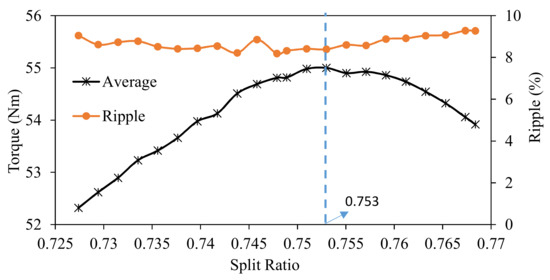
Figure 36.
Average torque and torque ripple against the split ratio.
4.5.2. Stator Slot
The influence of the stator geometric parameters, shown in Figure 35, on some major performance characteristics is parametrically investigated in this part. Note that the determined individual optimum values of each stator slot parameter are indicated in the related figures. Figure 37 shows the effect of the stator slot opening parameter on the torque, torque ripple, stator copper loss, and current density. The peak torque is achieved at 1.8 mm of and the torque ripple reduces remarkably as is increased. On the other hand, since has no effect on the stator slot area, no considerable change in the stator copper loss and current density is observed. The insignificant reduction in the stator copper loss is due to the slightly reduced harmonic content of the stator current.
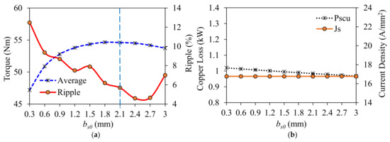
Figure 37.
Variations of some key performance characteristics with : (a) torque and torque ripple and (b) stator copper loss and current density.
Similarly, the effects of the stator slot width , stator slot-opening height , and stator slot height on torque, torque ripple, stator copper loss and current density are investigated parametrically, and the obtained results are shown in Figure 38, Figure 39 and Figure 40, respectively. As for , because of the reduction of the saturation level of the stator tooth parts, as seen in Figure 41, the narrower the stator slot, the higher the average torque (see Figure 38a). In addition, as the slot area is increased with the increasing , the copper loss and current density decrease remarkably, as seen in Figure 38b. Considering Figure 39, it can be concluded that also has a considerable effect on the torque and torque ripple but has no effect on the copper loss and current density. As for the dimensions larger than 5 mm of, the average torque starts to decrease due to an increase in the saturation level of stator yoke while the torque ripple starts to increase, as seen Figure 40a. In addition, an increase in results with an increased slot area and, hence, decreased copper loss and current density.
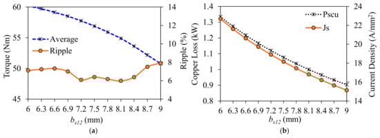
Figure 38.
Variation of some key performance characteristics with : (a) torque and torque ripple and (b) stator copper loss and current density.
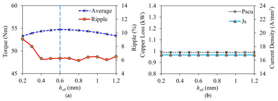
Figure 39.
Variation of some key performance characteristics with : (a) torque and torque ripple and (b) stator copper loss and current density.
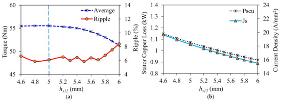
Figure 40.
Variation of some key performance characteristics with : (a) torque and torque ripple and (b) stator copper loss and current density.
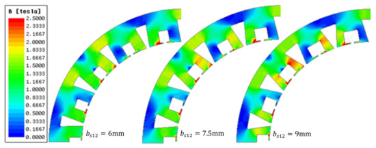
Figure 41.
Variation of the flux density amplitudes in stator teeth and yokes due to .
4.5.3. Rotor Slot
In a similar manner, the influence of the rotor slot parameters indicated in Figure 35 has been investigated, and the parametric analysis results are illustrated in Figure 42. It has been observed that each rotor slot parameter has a significant effect on the torque, torque density, rotor bar copper loss, and current density, individually. It has been revealed that the torque is quite sensitive to all rotor parameters, while torque ripple is more sensitive to the rotor slot width and rotor slot height parameters. The rotor copper loss , on the other hand, is very sensitive to the rotor slot opening width and the rotor slot opening height , whereas the current density is more sensitive to the and parameters. It has been revealed that the larger the rotor slot opening width , the higher the and the . The underlying causes of this phenomenon have been explained in References [32,33] in detail, as follows. Since the rotor teeth function as a low-pass filter, the smaller the slot-opening width, the more the higher-order harmonics are eliminated.
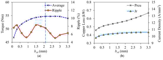
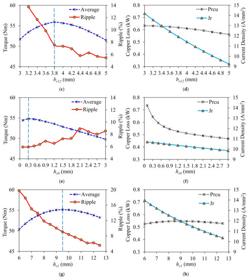
Figure 42.
Variation of some key performance characteristics with rotor parameters: (a) torque and torque ripple with ; (b) rotor bar copper loss and current density with ; (c) torque and torque ripple with ; (d) rotor bar copper loss and cur-rent density with ; (e) torque and torque ripple with ; (f) rotor bar copper loss and current density with ; (g) torque and torque ripple with ; (h) rotor bar copper loss and current density with .
On the other hand, since a smaller slot opening causes an increase of the magnitude of the short-circuited flux, the level of the average torque decreases, as seen in Figure 42a. Therefore, = 2.2 mm can be chosen as the individual optimum by considering and the . It has been observed from Figure 42c that the larger the , the lower the torque ripple and . Although decreases as is increased, does not change considerably, since the amount of induced bar current does not change (see Figure 42d). Consequently, the individual optimum of is determined as 3.8 mm. To increase causes an increase in the amount of short-circuited and, also, leakage fluxes. Therefore, as seen in Figure 42e, the average torque drops. Therefore, the individual optimum of is chosen as 0.3 mm. As for the parameter, the maximum torque is achieved at a 9.5-mm slot depth with a relatively low torque ripple (see Figure 42g). As seen in Figure 42h, as the is increased, decreases, since the slot area is increased. However, is kept constant, since the leakage flux level and, hence, the current harmonic content of the bar current are increased significantly, even if the bar diameter is increased.
In this section, the influence of the geometric design parameters on the major performance characteristics have been investigated, and the individual optimum values are obtained. However, to maximize the desired performance characteristics, a multi-objective global optimization treatment is required to take into account the cross-correlation between the different design parameters.
5. Discussion on the Validation of the FEA Results
As mentioned previously, all the results presented in this paper are based on simulations performed by 2D time-stepping FEA. Although FEA predictions are considered fairly reliable today, its results might be inaccurate due to the human errors in the modeling and analysis. Therefore, experimental validation of numerical results for at least one model could be required. In essence, in the previous publication [5] by the authors of this paper, the numerically calculated steady-state and flux-weakening performances and electric loading characteristics of a conventional IM with 54S/44R/6P-DL long-pitch ISDWs (), which has the same major design and operating parameters as its proposed AIM counterpart presented in this paper, are verified by measurements. Consequently, considering the well-agreed predicted and measured performance characteristics, such as torque, efficiency, torque/power-speed curves, etc., obtained from conventional IM [5], it can be predicted that the analysis results presented in this paper are reliable.
6. Conclusions
In this paper, an ANW topology for squirrel cage IMs has been developed to minimize the total axial length while concurrently improving the performance characteristics. It has been revealed that in combination with the auxiliary slot approach, the multi-layer phase winding shifting method results in a more uniform distribution of a winding layout with a greatly reduced MMF harmonic content. Thanks to the proposed method, a ~43% reduction in THD of MMF and a more than 25% reduction in the total axial length are achieved. Furthermore, very useful design guidelines are offered to establish the principal design parameters for squirrel cage IMs. The influence of major machine design parameters on the average torque, torque ripple, current density, machine losses, efficiency, and flux-weakening performance were also examined. Moreover, a comprehensive literature review on the performance improvement of IMs, with particular emphasis on MMF harmonic reduction methods, was presented. The following is a summary of some noteworthy results in this study.
- Compact IMs with high efficiency can be designed thanks to ANW topology;
- There is a critical rotor slot number for any S/P combination providing the maximum average torque with the minimum torque ripple;
- Poor performance characteristics such as a high bar current density, high slip and losses, and consequently, low efficiency are unavoidable in combinations where the number of rotor slots is significantly greater than the number of stator slots ();
- Selection of a high stack length results in a lower number of turns required to maintain the torque and, hence, a better flux-weakening capability.
- By keeping the pole number as low as possible, a wider constant power region can be achieved;
- Although each design parameter has a considerable effect on the performance characteristics individually, slot dimensions have a significant effect on the torque and current density, whereas slot opening dimensions have a remarkable effect on torque ripple and losses, particularly bar copper loss.
Multi-objective design optimization of AIMs, performance comparison with IPM machines and further performance improvement methods for AIMs will be presented in future works.
Author Contributions
Conceptualization and methodology, T.G. and Z.-Q.Z.; formal analysis, T.G.; investigation, T.G.; resources, Z.-Q.Z.; writing—original draft preparation, T.G.; writing—review and editing, Z.-Q.Z.; visualization, T.G.; software, T.G.; supervision, Z.-Q.Z. and J.-C.M.; project administration, Z.-Q.Z. and J.-C.M.; and funding acquisition, Z.-Q.Z. and J.-C.M. All authors have read and agreed to the published version of the manuscript.
Funding
This research was funded by Valeo Powertrain Electric Systems, 94017 Créteil CEDEX, France.
Data Availability Statement
Not Applicable.
Conflicts of Interest
The authors declare no conflict of interest.
Appendix A
Table A1.
Major specifications of the studied IMs.
Table A1.
Major specifications of the studied IMs.
| Parameter | 18S/6P/20R-DL (ANW) | |||||
|---|---|---|---|---|---|---|
| Number of coils per phase | 3 | 6 | 6 | 6 | 12 | 12 |
| Number of turns per coil | 14 | 9 | 12 | 12 | 9 | 8 |
| Number of parallel branch | 3 | 6 | 6 | 6 | 12 | 12 |
| Stator outer diameter (mm) | 144 | |||||
| Stator inner diameter (mm) | 96.48 | 99.36 | 99.072 | 95.04 | 93.312 | 108.432 |
| Split ratio | 0.67 | 0.69 | 0.688 | 0.66 | 0.648 | 0.753 |
| Air-gap length (mm) | 0.35 | |||||
| Rotor outer diameter (mm) | 95.78 | 98.66 | 98.372 | 94.34 | 92.612 | 107.732 |
| Stator tooth width/height (mm) | 15.6/11.7 | 8.73/10.3 | 8.96/12.2 | 9/12.8 | 4.26/10 | 4.3/10 |
| Stator/rotor slot opening width (mm) | 8/5.5 | 4/1.4 | 4.5/2 | 4/4 | 1.75/1.5 | 1.7/1.35 |
| Rotor tooth width/ height (mm) | 11.13/11.9 | 8.26/14 | 8.67/14.5 | 8.8/12.2 | 5.5/11.9 | 5.3/11.7 |
| Stack length (mm) | 70 | 110 | ||||
| Core lamination | Material: M270-35A. Lamination stacking factor: 0.95. Lamination thickness: 0.305 mm. | |||||
| Bar material | Copper 75 °C | |||||
* Maximum Inverter ratings: 500 Arms and 48 Vdc.
References
- Diaz, S.; Tietge, U.; Mock, P. CO2 emissions from new passenger cars in the EU: Car manufacturers’ performance in 2015. Int. Counc. Clean Transp. 2016. Available online: www.theicct.org/co2-from-new-cars-eu-2015 (accessed on 18 September 2021).
- Toliyat, H.A.; Lipo, T.A.; White, J.C. Analysis of a concentrated winding induction machine for adjustable speed drive applications. II. Motor design and performance. IEEE Trans. Energy Convers. 1991, 6, 684–692. [Google Scholar] [CrossRef]
- El-Refaie, A.M.; Shah, M.R. Comparison of induction machine performance with distributed and fractional-slot concentrated windings. In Proceedings of the 2008 IEEE Industry Applications Society Annual Meeting, Edmonton, AB, Canada, 5–9 October 2008; pp. 1–8. [Google Scholar] [CrossRef]
- Wang, K.; Zhu, Z.Q.; Ombach, G. Synthesis of high performance fractional-slot permanent-magnet machines with coil-pitch of two slot-pitches. IEEE Trans. Energy Convers. 2014, 29, 758–770. [Google Scholar] [CrossRef]
- Gundogdu, T.; Zhu, Z.-Q.; Mipo, J.-C. Analysis of coil pitch in induction machines for electric vehicle applications. IET Electr. Power Appl. 2020, 14, 2525–2536. Available online: https://digital-library.theiet.org/content/journals/10.1049/iet-epa.2019.0980 (accessed on 8 September 2021).
- Gundogdu, T.; Komurgoz, G.; Mantar, B. Implementation of fractional slot concentrated windings to Induction Machines. In Proceedings of the 7th IET International Conference on Power Electronics, Machines and Drives (PEMD 2014), Manchester, UK, 8–10 April 2014; pp. 1–6. [Google Scholar] [CrossRef]
- Eastham, J.F.; Cox, T.; Proverbs, J. Application of planar modular windings to linear induction motors by harmonic cancellation applications. IET Electr. Power Appl. 2010, 4, 140–148. Available online: https://digital-library.theiet.org/content/journals/10.1049/iet-epa.2009.0086 (accessed on 6 September 2021).
- Jensen, B.B.; Jack, A.G.; Atkinson, G.J.; Mecrow, B.C. Performance of a folded-strip toroidally wound induction machine. IEEE Trans. Ind. Electron. 2012, 59, 2217–2226. [Google Scholar] [CrossRef]
- Alberti, L.; Bianchi, N. Design and tests on a fractional-slot induction machine. In Proceedings of the 2012 IEEE Energy Conversion Congress and Exposition (ECCE), Raleigh, NC, USA, 15–20 September 2012; pp. 166–172. [Google Scholar] [CrossRef]
- Sundaram, V.M.; Toliyat, H.A. A fractional slot concentrated winding (FSCW) configuration for outer rotor squirrel cage induction motors. In Proceedings of the 2015 IEEE International Electric Machines & Drives Conference (IEMDC), Coeur d’Alene, ID, USA, 10–13 May 2015; pp. 20–26. [Google Scholar] [CrossRef]
- Sakai, K.; Suzuki, M.; Takishima, K. Induction machines with novel concentrated windings. In Proceedings of the 2017 IEEE International Electric Machines and Drives Conference (IEMDC), Miami, FL, USA, 21–24 May 2017; pp. 1–7. [Google Scholar] [CrossRef]
- Jack, A.G.; Mecrow, B.; Krogen, O. Induction Machine Stator. U.S. Patent 6,815,863 B1, 9 November 2005. [Google Scholar]
- Misir, O.; Ponick, B. Analysis of three-phase induction machines with combined star-delta windings. In Proceedings of the 2014 IEEE 23rd International Symposium on Industrial Electronics (ISIE), Istanbul, Turkey, 1–4 June 2014; pp. 756–761. [Google Scholar] [CrossRef]
- Park, Y.; Yoo, J.; Sul, S. Double-delta sourced winding for dual winding induction machine. In Proceedings of the 2015 9th International Conference on Power Electronics and ECCE Asia (ICPE-ECCE Asia), Seoul, Korea, 1–5 June 2015; pp. 77–85. [Google Scholar] [CrossRef]
- Gieras, J.F.; Rozman, G.I. Reduction of Leakage Flux in Electrical Machines. U.S. Patent 2014/0,354,106 A1, 4 December 2014. [Google Scholar]
- Moros, O.; Gerling, D. Geometrical and electrical optimization of stator slots in electrical machines with combined wye-delta winding. In Proceedings of the 2014 International Conference on Electrical Machines (ICEM), Berlin, Germany, 2–5 September 2014; pp. 2026–2030. [Google Scholar] [CrossRef]
- Dajaku, G.; Gerling, D. Different novel electric machine designs for automotive applications. In Proceedings of the 2013 World Electric Vehicle Symposium and Exhibition (EVS27), Barcelona, Spain, 17–20 November 2013; pp. 1–7. [Google Scholar] [CrossRef]
- Wang, J.; Patel, V.I.; Wang, W. Fractional-slot permanent magnet brushless machines with low space harmonic contents. IEEE Trans. Magn. 2014, 50, 1–9. [Google Scholar] [CrossRef]
- Abdel-Khalik, A.S.; Diab, M.S.; Ahmed, S.; Massoud, A.M. A new single tooth winding layout for a single-phase induction motor with segmented stator. In Proceedings of the IECON 2015—41st Annual Conference of the IEEE Industrial Electronics Society, Yokohama, Japan, 9–12 November 2015; pp. 102–107. [Google Scholar] [CrossRef]
- Alberti, L.; Bianchi, N. Analysis of asynchronous machines for direct drive wind power generation. In Proceedings of the 2009 IEEE International Electric Machines and Drives Conference, Miami, FL, USA, 3–6 May 2009; pp. 1838–1843. [Google Scholar] [CrossRef]
- Jung, T.; Yun, C.; Cha, H.; Chae, M.; Kim, H. Improved design for driving characteristics in single phase induction motor with concentrated winding. In Proceedings of the 2007 IEEE Power Electronics Specialists Conference, Orlando, FL, USA, 17–21 June 2007; pp. 2418–2422. [Google Scholar] [CrossRef]
- Virlan, B.; Simion, A.; Livadaru, L.; Benelghali, S.; Outbib, R. Analysis of a three phase induction motor with outer rotor for multi-speed applications. In Proceedings of the 2012 XXth International Conference on Electrical Machines, Marseille, France, 2–5 September 2012; pp. 411–417. [Google Scholar] [CrossRef]
- Dajaku, G.; Spas, S.; Dajaku, X.; Gerling, D. An improved fractional slot concentrated winding for low-poles induction machines. In Proceedings of the 2016 XXII International Conference on Electrical Machines (ICEM), Lausanne, Switzerland, 4–7 September 2016; pp. 114–119. [Google Scholar] [CrossRef]
- Abdel-Khalik, A.S.; Ahmed, S.; Massoud, A. A five-phase linear induction machine with planar modular winding. In Proceedings of the 2015 IEEE International Conference on Industrial Technology (ICIT), Seville, Spain, 17–19 March 2015; pp. 580–585. [Google Scholar] [CrossRef]
- Xu, Y.; Xu, Z.; Ai, M. Application of ring winding in induction motor. IEEE Trans. Appl. Supercond. 2021, 31, 1–5. [Google Scholar] [CrossRef]
- Mallampalli, S.; Zhu, Z.Q.; Mipo, J.C.; Personnaz, S. Six-phase pole-changing winding induction machines with improved performance. IEEE Trans. Energy Convers. 2021, 36, 534–546. [Google Scholar] [CrossRef]
- Mallampalli, S.; Zhu, Z.Q.; Mipo, J.C.; Personnaz, S. 48 V starter-generator induction machine with pole-changing windings. IEEE Trans. Ind. Appl. 2020, 56, 6324–6337. [Google Scholar] [CrossRef]
- Muteba, M. Optimization of air gap length and capacitive auxiliary winding in three-phase induction motors based on a genetic algorithm. Energies 2021, 14, 4407. [Google Scholar] [CrossRef]
- Zhang, M.; Eastham, F.; Yuan, W. Design and modeling of 2G HTS armature winding for electric aircraft propulsion applications. IEEE Trans. Appl. Supercond. 2016, 26, 1–5. [Google Scholar] [CrossRef]
- Zhu, Z.Q.; Liu, X. Individual and global optimization of switched flux permanent magnet motors. In Proceedings of the 2011 International Conference on Electrical Machines and Systems, Beijing, China, 20–23 August 2011; pp. 1–6. [Google Scholar] [CrossRef]
- Gundogdu, T. Advanced Non-Overlapping Winding Induction Machines for Electrical Vehicle Applications. Ph.D. Thesis, University of Sheffield, Sheffield, UK, 2018. Available online: https://etheses.whiterose.ac.uk/20728/ (accessed on 18 February 2021).
- Gundogdu, T.; Zhu, Z.Q.; Mipo, J.C.; Farah, P. Investigation of non-sinusoidal rotor bar current phenomenon in induction machines—Influence of slip and electric loading. In Proceedings of the 2016 XXII International Conference on Electrical Machines (ICEM), Lausanne, Switzerland, 4–7 September 2016; pp. 419–425. [Google Scholar] [CrossRef]
- Gundogdu, T.; Zhu, Z.Q.; Mipo, J.C.; Farah, P. Influence of magnetic saturation on rotor bar current waveform and performance in induction machines. In Proceedings of the 2016 XXII International Conference on Electrical Machines (ICEM), Lausanne, Switzerland, 4–7 September 2016; pp. 391–397. [Google Scholar] [CrossRef]
- Gundogdu, T.; Zhu, Z.Q.; Mipo, J.C. Influence of stator slot and pole number combination on rotor bar current waveform and performance of induction machines. In Proceedings of the 2017 20th International Conference on Electrical Machines and Systems (ICEMS), Sydney, Australia, 11–14 August 2017; pp. 1–6. [Google Scholar] [CrossRef]
- Gundogdu, T.; Zhu, Z.Q.; Mipo, J.C. Influence of rotor slot number on rotor bar current waveform and performance in induction machines. In Proceedings of the 2017 20th International Conference on Electrical Machines and Systems (ICEMS), Sydney, Australia, 11–14 August 2017; pp. 1–6. [Google Scholar] [CrossRef]
- Besnerais, J.L.; Lanfranchi, V.; Hecquet, M.; Brochet, P. Optimal slot numbers for magnetic noise reduction in variable-speed induction motors. IEEE Trans. Magn. 2009, 45, 3131–3136. [Google Scholar] [CrossRef]
- Gyftakis, K.N.; Kappatou, J. The impact of the rotor slot number on the behaviour of the induction motor. Adv. Power Electron. 2013, 2013, 837010. [Google Scholar] [CrossRef][Green Version]
- Lipo, T.A. Calculation of Induction Machine Losses. In Introduction to AC Machine Design; Wiley-IEEE Press: Piscataway, NJ, USA, 2018; pp. 193–250. [Google Scholar] [CrossRef]
- Guan, Y. Torque-speed characteristics of induction machine and hybrid permanent magnet assisted synchronous reluctance machine for electric vehicle application. Ph.D. Thesis, University of Sheffield, Sheffield, UK, 2015. Available online: https://etheses.whiterose.ac.uk/7867/ (accessed on 1 September 2021).
Publisher’s Note: MDPI stays neutral with regard to jurisdictional claims in published maps and institutional affiliations. |
© 2021 by the authors. Licensee MDPI, Basel, Switzerland. This article is an open access article distributed under the terms and conditions of the Creative Commons Attribution (CC BY) license (https://creativecommons.org/licenses/by/4.0/).