Article

Design and Validation of Demanded Power Point Tracking Control Algorithm for MIMO Controllers in Wind Turbines

1
Department of Integrated Energy & Infra System, Kangwon National University, Gangwon, Chuncheon 24341, Korea
2
Department of Advanced Mechanical Engineering, Kangwon National University, Gangwon, Chuncheon 24341, Korea
3
Department of Mechatronics Engineering Kangwon National University, Gangwon, Chuncheon 24341, Korea
*
Author to whom correspondence should be addressed.
Energies 2021, 14(18), 5818; https://doi.org/10.3390/en14185818
Submission received: 4 August 2021 / Revised: 8 September 2021 / Accepted: 13 September 2021 / Published: 14 September 2021
(This article belongs to the Special Issue Real-Time Monitoring and Control for Wind Turbine Systems)

Abstract

:
In this study, a demanded power point tracking (DPPT) control algorithm was designed for the application of multiple-input multiple-output (MIMO) modern control algorithms. The proposed DPPT control algorithm has been newly implemented as a multiple reference trajectory method for applying an MIMO control algorithm without mode switches. Dynamic simulations and wind tunnel experiments were performed using a scaled wind turbine to validate the proposed control algorithm. The wind speeds were 4.6 and 7.3 m/s, the average wind speeds corresponding to region 2 and region 3, respectively, with a turbulence intensity of 10%. Both sets of results demonstrated satisfactory performance for tracking the power commands transmitted from the wind farm controller. Furthermore, the proposed control algorithm was compared and validated with a DPPT control algorithm proposed in previous studies, and its improved control performance and validity were confirmed.

1. Introduction

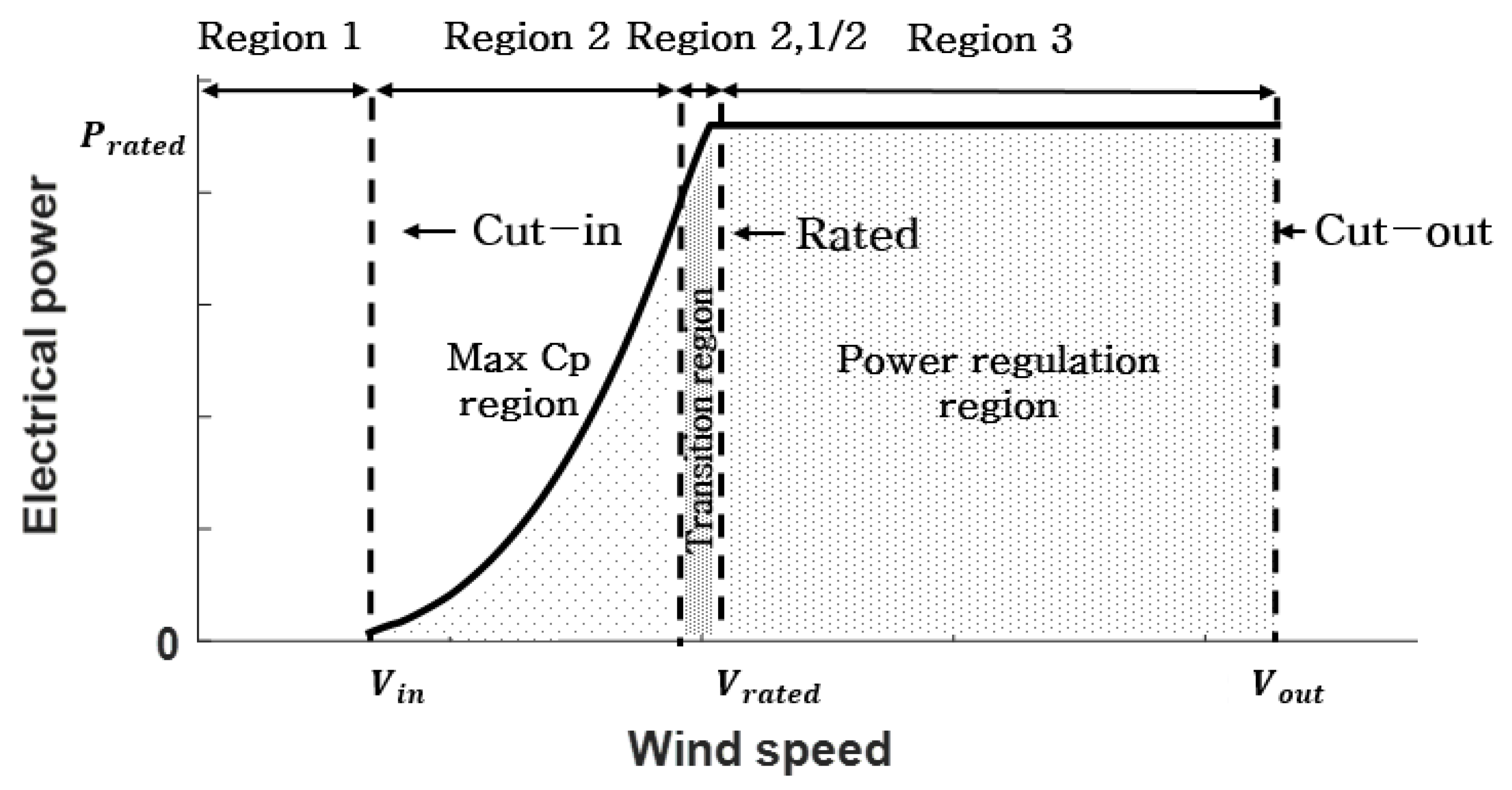
Wind turbine control systems are implemented to allow the wind turbines to operate automatically while responding appropriately to changes in wind speed and direction. In a region with wind speeds lower than the rated wind speed, the generator torque is controlled to ensure that the wind turbine tracks the maximum power points while the blade pitch angle is maintained at the fine pitch angle. In a region with a speed higher than the rated wind speed, the blade pitch angle is controlled to maintain the rated generator speed of the wind turbine, and at the same time, the generator torque is fixed at the rated value or slightly adjusted to maintain the rated power [1].
This basic power control of wind turbines can be achieved by either single-input single-output (SISO) or multiple-input multiple-output (MIMO) control, based on the way they deal with inputs and outputs. The PI or PID control, which has been utilized in various fields as a classical SISO control, has been conventionally implemented to control wind turbines. This method consists of two SISO loops, each capable of controlling the blade pitch angle and the generator torque, to generate power with different strategies for different wind speed regions [1]. SISO control algorithms for wind turbines were further developed to provide new strategies for improving power performance and reducing mechanical load.
Drivetrain dampers are used to reduce the fatigue load of the low-speed shaft caused by the vibrations of the drivetrain torsional mode [2]. This damper increases the damping ratio of the drive train by calculating the torque command for the generator speed signal through the band pass filter. Tower dampers are known to reduce the vibrations of tower fore-aft mode in the rated power region [3]. This damper consists of a proportional control loop of the pitch angle relative to the nacelle acceleration signal with the phase compensator to secure phase margins. The tower vibration could also be reduced by torque commands through resonance avoidance strategies [4]. Peak shaving using additional pitch angles for situations where rotor speed is rapidly increasing can avoid frequent shutdowns of wind turbines due to gusts [5]. The feed-forward pitch control method using a wind-speed estimator alleviates power fluctuations in the rated power region [6]. Using artificial neural networks and genetic algorithms helped to address the power tracking problem in the SISO control loop for unpredictable wind uncertainty, improving its performance [7]. These algorithms are implemented as a feed-forward loop so that the maximum power can be tracked in the conventional PI control loop.
However, because this SISO control is based on a single input, all the effects caused by various wind turbine states cannot be considered simultaneously for control. This is an avoidable constraint on the improvement of the controller performance. Therefore, MIMO control, which can simultaneously take into account various states of wind turbines, was investigated as an alternative allowing for better performance.
By designing an LQR controller using multiple state feedback control methods, simulations demonstrated a reduction in power variation of up to 46% and a 20% reduction in tower load compared to the conventional PI control algorithm [8]. Studies were also conducted on LQG algorithms with noise-considered state estimators using Kalman filters, and simulations have shown up to a 24% reduction in power variation and a 66% blade load reduction compared to the conventional PI control algorithms [9]. The MPC method showed a torsional load reduction performance of up to 52% for low-speed shafts through hardware in the loop system when compared to the conventional PI control algorithms [10]. The control technique for considering the nonlinearity of wind turbines was also studied by applying fuzzy inference techniques to the optimal control algorithms. Up to a 39% power variation reduction and a 13% tower vibration reduction were confirmed through wind tunnel experiments using an LQR control algorithm based on fuzzy logic (LQRF) [11]. During dynamic simulation, the H control showed a tower and blade fatigue load reduction of up to 8% and 26%, respectively, compared to the conventional PI control algorithms [12].
Unlike the wind turbine control algorithms, which are used to improve the load and the power of individual wind turbines, control algorithms to increase the total power production of wind farms, and have recently become a topic of interest [13,14,15]. In this case, the upstream wind turbines must be controlled such that they do not to track their own maximum power point, but instead track the power demand from a wind farm controller, which is slightly lower than the maximum power point [14]. This results in a slight decrease in the power output of the upstream wind turbines, but an increase in the power output of the downstream wind turbines. As the result, an increase in the total power of the wind farm is achieved. This approach is known as active induction control [15].
For active induction control to be implemented in a real wind farm, the individual wind turbine controller must be modified appropriately regardless of the control types being employed (i.e., SISO or MIMO controllers). The wind turbine controller needs to operate using its original power control when there is no power demand from a wind farm controller, but must track the power demand whenever it occurs. This is known as active power control (APC) or demanded power point tracking (DPPT) control.
Jeong et al. proposed several APC methods [16]. Through simulations and field tests with a 550 kW wind turbine, a method to obtain rotor speed set-points according to demanded power points was proposed, using the generator torque and blade pitch angle together. A study by Kim et al. used a mode switch to turn on the demanded power point tracking control according to power commands from a wind farm controller [17]. The proposed algorithm was validated by using a wind tunnel experiment and a field test with a 100 kW wind turbine [18]. Bottasso et al. considered partialization using a strategy to maintain a constant tip speed ratio (TSR) [19]. The proposed control algorithm was verified on a motor-generator set simulator, but no experimental verification was performed using wind turbines.
The DPPT algorithms previously proposed in the literature showed promising power tracking capabilities. However, all of them were applicable to the classical SISO control algorithms (PI or PID) of a wind turbine, but cannot be implemented for MIMO control algorithms. Furthermore, although the superior control performance of modern MIMO control algorithms has been demonstrated, no DPPT controls, which can be implemented for MIMO control, were found in the existing literature.
Therefore, the purpose of this study is to design a demanded power point tracking (DPPT) control algorithm for application to an MIMO-type modern control algorithm (LQRF) and to verify its tracking performance through wind tunnel experiments. The proposed DPPT control algorithm for application to an MIMO controller cannot be designed solely using the rotor speed feedback method applied to conventional PI control algorithms. Thus, a suitable DPPT control method was applied to modern control algorithms based on an MIMO that used a multiple reference trajectory method.
The originality and contribution of this study can be summarized as follows:
The proposed DPPT control algorithm was designed to be applied to a variety of MIMO modern control algorithms, instead of to traditional PI control methods. Previous studies have shown that despite the satisfactory performance of the MIMO-type modern control algorithms, they have not yet been used for studies on the design and validation of DPPT controllers for wind farm control. Therefore, strategies for applying conventional DPPT control techniques to modern MIMO control algorithms that have completely different structures from classical PI control are analyzed herein. The DPPT controller was designed using multiple reference trajectory techniques without mode switches in order to suit MIMO-type modern control algorithms, and was experimentally validated through simulations and wind tunnel experiments. To ensure the validity and suitability of the proposed control algorithm, the proposed DPPT control algorithm was compared with the DPPT control algorithm developed in previous studies, and their control performance was analyzed through simulations. The results of this study are expected to serve as a reference study which will enable wind farm controllers to control individual wind turbines by using MIMO-type modern control algorithms.
This paper consists of six sections. Section 2 describes the target wind turbine used for verifying the controller. Section 3 provides a description of the control strategy and the controller design. Section 4 describes the simulations and wind tunnel experiments performed to validate the proposed control algorithm. The control response to tracking the demanded power from the wind farm controller is confirmed by the time-series data. Section 5 compares the control performance with other DPPT control algorithms through a dynamic simulation to enhance the validity of the proposed control algorithm. Lastly, Section 6 describes the conclusions of this study.

2. Target Wind Turbine

The target wind turbine selected for the simulation and the wind tunnel experiments for validating the proposed control algorithm was a scaled wind turbine with variable-speed variable-pitch (VSVP) and a horizontal axis. The scaled wind turbine was originally designed and developed by researchers at the University of Technology in Munich [20], and was modified to use three-dimensional (3D) printed blades and the new control algorithms, in order to allow for the experimental validation of this study [21].
The rated electrical power of the target wind turbine was 46 W, with a rotor diameter of 1.1 m and a hub height of 0.9 m. Since the TSR in the operation region of the target wind turbine was designed to be approximately 7–8, the operating characteristics were similar to those of an actual medium or large wind turbine. Therefore, the target wind turbine was suitable for use as a wind turbine model for the experimental validation of the proposed control algorithm [22]. The other specifications of the target wind turbine are presented in Table 1. Figure 1 shows an image of the target wind turbine.

3. Controller Design

The performance analysis of the target wind turbine should be performed first in order to design the controller. Once aerodynamic performance, power performance, and the dynamic characteristics of the target wind turbine are identified, the LQRF and DPPT control strategies can be established based on this information. The LQRF controller is the MIMO controller created by using the wind speed estimator, LQR controllers, and the fuzzy model. The weights and gains of the LQRF controller are tuned through simulations and wind tunnel experiments. The proposed DPPT controller is designed by establishing the trajectory planning of the primary states based on a power derating strategy. The trajectory planning is constructed through iterating steady-state simulations. The MIMO-type DPPT controller, which is completed by combining the two algorithms, completed the final design through the re-tuning process and validated its validity through the resulting analysis.
Flowchart of design and validation for MIMO controller with DPPT are shown in Figure 2.

3.1. Control Strategy

The control strategy of horizontal-axis VSVP wind turbines can be divided into three regions according to the wind speeds [1]. Region 1 is the section below to the cut-in wind speed and does not generate wind power. Region 2 is the range from the cut-in wind speed to the rated wind speed, wherein the blade pitch angle is maintained at a fine pitch angle, and the generator torque is applied so that the wind turbine tracks the maximum power points. Region 3 is the region from the rated wind speed to the cut-out wind speed, wherein the generator torque is maintained at the rated torque level, and the blade pitch angle is controlled to maintain the rated power. Region 2-1/2 is the transition region between regions 2 and 3, where the two control strategies are switched. Figure 3 shows a typical power control strategy for wind turbines.
However, the power control strategy shown in Figure 3 only considers a single wind turbine. In a wind farm, some wind turbines may be derated to a certain level in order to improve the total power production or to regulate the power transmitted to the grid. Equation (1) indicates the power that wind turbines can extract from wind [1], and shows that the power coefficient C P , determined by the TSR λ and blade pitch angle β , must be reduced to reduce the power.
P = 1 2 ρ π R 2 v 3 C P ( λ , β )
The strategy for reducing the power coefficient in order to derate the power is shown in Figure 4. The pitch angle is divided into 2.5° intervals from −2.0° to 15.5°, indicating the power coefficient (Figure 4a) and thrust coefficient (Figure 4b) of the scaled model, which vary depending on the TSR. As shown in Figure 4, a situation in which the power is reduced by 60% when the wind turbine is under control at the maximum power point can be assumed. Although there are numerous ways to derate power points, the strategies to change the TSR can be divided into three strategies: A, B, and C [19].
Strategy A in Figure 4 reduces the rotor speed because it uses a large pitch angle compared to Strategies B and C. Therefore, because the thrust generated by the rotor of the wind turbine is low, the wake deficit effect in the wind farm is high [23]. However, when used to reduce some power production from wind farms to regulate the power, the minimum rotor speed required for the grid connection may not be reached owing to a simple decrease in rotor speed. This can lead to a frequent shutdown in region 2. Strategy B maintains a constant rotor speed. Therefore, as the sensitivity of the control loop gain to the rotor speed does not change with wind speed, new tuning is not required. Strategy C is a strategy that increases rotor speed and in which pitch angles are rarely used, and involves the smallest wake deficit effect. This strategy is suitable for stall-regulated wind turbines. However, this method of increasing the rotor speed may cause the maximum rotor speed to exceed the limit at which it must be shut down. That is, strategies A and C, which change the rotor speed, can cause gain-tuning problems [16,17,18]. In a previous study, the sensitivity change was attributed to the recovery of, and decrease in, the rotational kinetic energy of wind turbines [17]. However, strategy B has relatively small wake deficit effects, with a lower pitch angle usage compared to strategy A. In Figure 4b, Strategy A reduces the thrust coefficient by approximately 0.54 by using a pitch angle of approximately 13°. For strategy B, the thrust coefficient was reduced by approximately 0.47, owing to the use of a pitch angle of approximately 7.5°. Although the reduction in thrust coefficients is lower in areas where the pitch angle is greater than 5°, the thrust coefficient is still higher in strategy B than in strategy A; thus, strategy B has a relatively smaller wake deficit effect than strategy A. Based on the characteristics of the strategies, the DPPT control algorithm should properly consider the control sensitivity of the target wind turbine, the rotor speed limiting conditions, and the wake deficit effects.
Since the MIMO control algorithm has many control gains and weights to control the states of a wind turbine, the control algorithm proposed in this study was designed based on strategy B, which maintains the same rotor speed to enhance the stability of the control system.

3.2. DPPT Control

In the MIMO control algorithm, each state tracks the reference trajectory. Reference trajectories generally use steady-state analysis results, but the reference trajectories of rotor speed, blade pitch angle, and generator torque have been modified for DPPT control, since they are the main variables determining the power. The modified reference trajectories are presented in Table 2.
According to the power control strategies in Figure 3, the reference trajectory for DPPT can be determined by dividing it into regions 2 and 3 based on the rated wind speed. The DPPT B strategy was adopted, as shown in Figure 4, so that the reference trajectory of the rotor speed is the same as the non-partialized steady-state analysis result. In region 2, the rotor speed increases proportionally to the wind speed. In region 3, the rotor speed is maintained at the rated rotor speed. The reference trajectory of the torque is determined by multiplying the steady-state analysis result by the partialization factor, p. In region 2, the torque is controlled in order to track the maximum power point. In region 3, the rated power is maintained by dividing it by the rated rotor speed. The determined trajectory is partialized by the partialization factor. The reference trajectory of the pitch is determined by adding the delta pitch angle, determined by the partialization factor p, and wind speed to the steady-state analysis results. In region 2, the pitch angle is maintained at a fine pitch angle in order to track the maximum power point. In region 3, the pitch angle is controlled in order to maintain the rated power. The determined trajectory is partialized by the delta pitch angle.
Figure 5 shows the delta pitch angle function in a three-dimensional (3D) form. Delta pitch angles are nonlinear functions determined by inputting wind speeds and the partialization factor, and then calculated by offline simulations. Figure 6 shows the reference trajectory from Table 2 according to the partialization factor, along with the steady-state results that are not partialized. The partialization was divided into five categories—20%, 40%, 60%, 80%, and 100%—and then interpolated to each reference trajectory based on the plan in Table 2.

3.3. LQRF Control Algorithm with DPPT Control

In this study, the LQRF control algorithm was applied as a target MIMO-type modern control algorithm. The LQRF control algorithm is a nonlinear modern control technique that combines the LQR optimal control technique with the fuzzy inference technique [11]. The LQR control algorithm calculates the optimal control inputs by solving a linear quadratic function for multiple states.
The state vector and input vector are described by Equation (2). The state vector was applied with a tower fore-aft displacement and velocity, rotor speed, pitch angle, pitch rate, torque, and integral action for the rotor speed. The input vector was applied with the pitch angle and torque commands.
x = [ d f a   d f a ˙ Ω r β C P C β C P C ˙ T g Ω r d t ] T u = [ β C M D T g   C M D ] T
Equation (3) is a linear quadratic function for calculating the optimal gain, and the calculation was performed using MATLAB (R2019b, The MathWorks, Inc., Natick, MA, USA) program to solve the algebraic Riccati equation (ARE). The Q and R matrices are weight matrices for the states and inputs, respectively.
J = ( x T ( t ) Q i x ( t ) + u T ( t ) R i u ( t ) ) d t
When the LQR controller is designed as multiple subsystems, the nonlinearity characteristics can be considered through fuzzy interpolation. The control commands calculated through fuzzy interpolation can be represented as:
u ( t ) = i = 1 N μ i ( z ( t ) ) μ i ( z ( t ) ) ( u i + K L Q   i ( x i ( t ) ) ) 0 μ ( z ( t ) ) < 1 ;     i = 1 N
where μ is the membership function, z is the system decision variable, i is the number of subsystems, and K L Q is the optimal gain obtained by solving the linear quadratic (LQ) problem. The content of the fuzzy logic used in this study is more completely described in Ref. [11].
The proposed overall control algorithm is illustrated in Figure 6. Figure 7a shows a block diagram for the conventional LQRF control algorithm, whereas Figure 7b shows the LQRF control algorithm with the DPPT control algorithm. The control algorithm shown in Figure 7b is represented by KNUm in this study. The reference trajectory in Figure 6 was applied to the controller in the form of a look-up table using the power command transmitted from the wind farm control algorithm and the estimated wind speed information. The set points at each state were calculated in real time using these look-up tables.

3.4. Wind Speed Estimator with DPPT Control

The wind speed estimator used in this study estimates the aerodynamic torque and wind speed structurally, through formulas with information input in real time for the torque, rotor speed, and pitch angle [6]. Therefore, it is necessary to examine whether the wind speed estimator can operate normally in unusual situations caused by different set points using the DPPT control algorithm.
The aerodynamic torque generated by wind on a wind turbine can be obtained from the governing equation of the drive-train motion model:
T a = ( J r + N 2 J g ) d Ω r d t + N T g + T l o s s
where J r is the rotor moment of inertia, J g is the generator moment of inertia, N is the gear ratio, and T l o s s is the loss in torque. The wind speed can be estimated using the estimated aerodynamic torque and the torque coefficient obtained in advance through an aerodynamic analysis. Equation (6) indicates the estimated wind speed:
T ^ a = 1 2 ρ π R 3 C Q ( λ ^ , β ) v ^ 2
The estimated wind speed was calculated in the form of a 3D look-up table obtained by reducing the error in the estimation of the aerodynamic torque through the optimization function in MATLAB. During the calculation of Equation (5), a lower aerodynamic torque is estimated than when DPPT control does not occur, since the rotor speed is the same but a lower torque is applied because of the DPPT control action. However, during the calculation of Equation (6), the torque coefficient decreases because the pitch angle changes owing to the DPPT control action. Consequently, the final wind speed estimate is expected to be the same regardless of the DPPT control. Figure 8 shows the results of the simulation of the aerodynamic torque and the wind speed estimated by the wind speed estimator depending on DPPT control.
The estimated wind speed was compared to the rotor-averaged wind speed extracted from the commercial analysis program DNVGL-Bladed (4.6, DNV-GL, Norway, Oslo) to verify the estimation performance. Figure 8 shows that when performing DPPT control, the aerodynamic torque was estimated to be low according to the level of partialization, but the wind speed was estimated to be normal owing to the lowered torque coefficient due to the pitch angle used.

4. Controller Validation

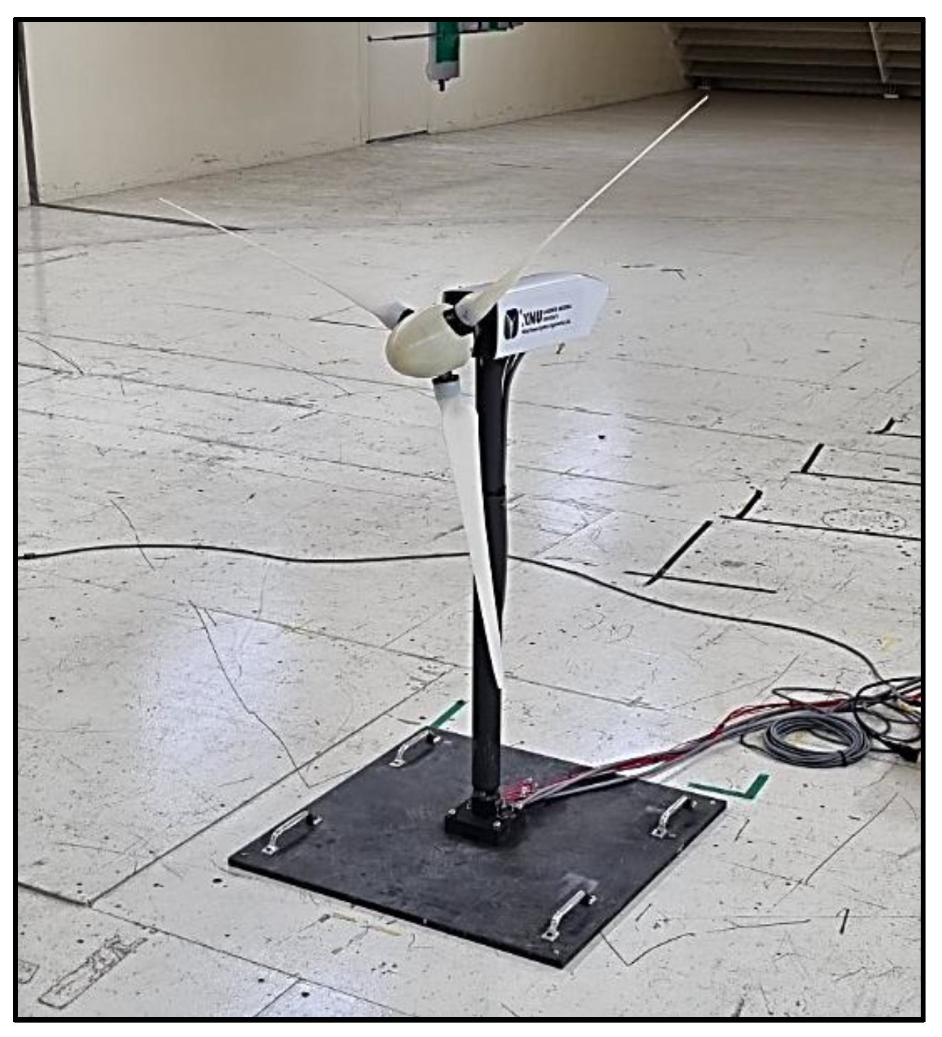
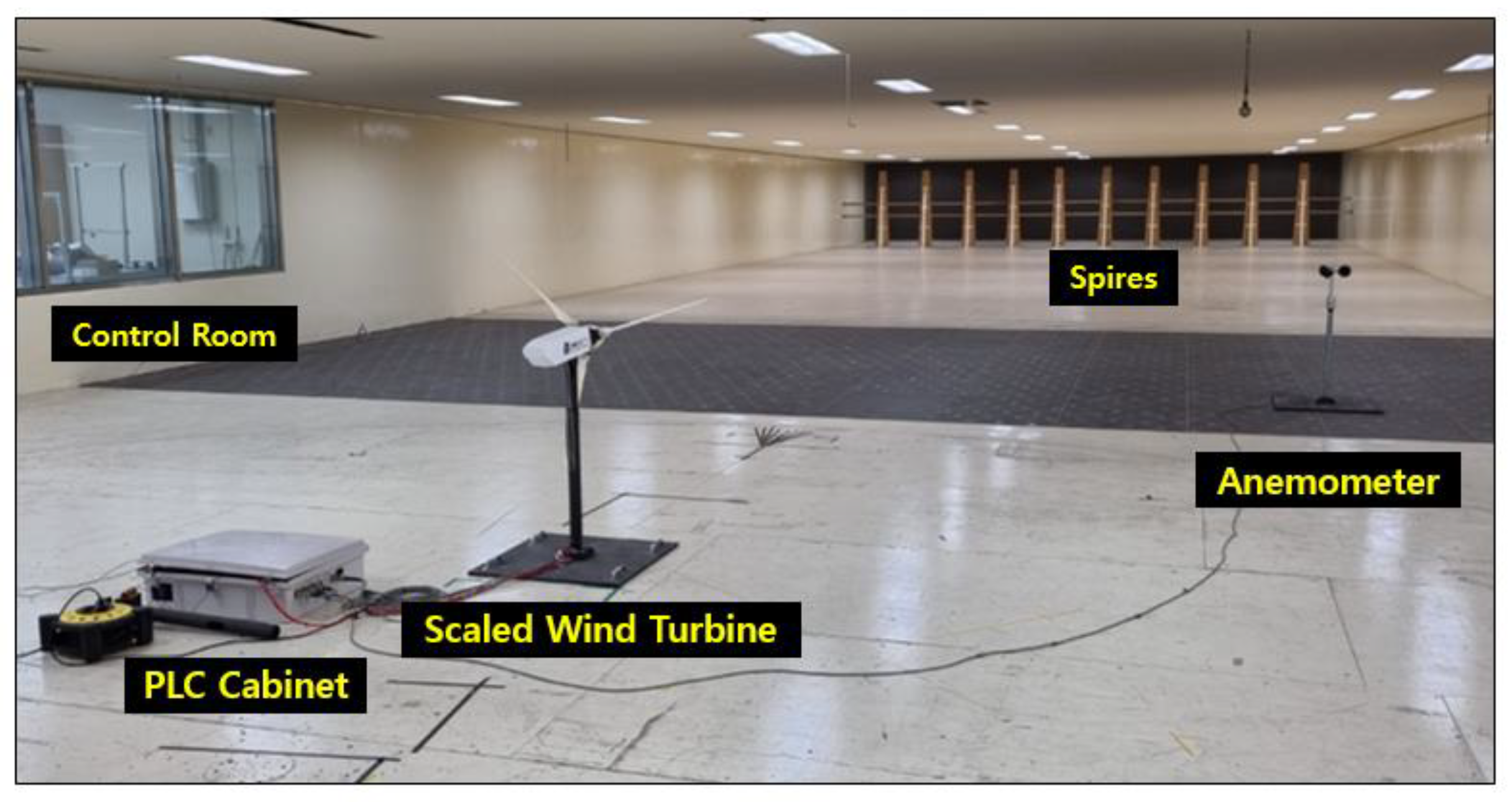
The performance and applicability of the proposed DPPT control algorithm for the MIMO controller (KNUm) were validated by conducting a wind tunnel experiment at a large wind tunnel test center (Jeolla-do, Korea). The wind tunnel is an internal circulation structure wherein the first and second floors are circulated. The experiment was conducted in the wind tunnel on the first floor, a low wind speed test floor. The dimensions of the wind tunnel were 40 × 12 × 2.5 m. The wind tunnel was observed from the control room. The personal computer (PC) in the control room and programmable logic controller (PLC) in the wind tunnel were connected in order to monitor and operate the scaled wind turbine. The C++ code-based controllers were uploaded to the PLC to control the actuators of the scaled wind turbine in real time (250 Hz sampling). The wind conditions were implemented using large blowers and hot-wire anemometers, and a 10% turbulence intensity was implemented using spire structures to perform more realistic wind tunnel experiments. The experiments were conducted by implementing wind conditions in region 2 (4.6 m/s) and region 3 (7.3 m/s) to confirm that the proposed control algorithm tracked the reference trajectory shown in Table 2. Figure 9 shows the control experiments performed using a scaled wind turbine inside a wind tunnel.
Furthermore, to validate the proposed control algorithm, the wind tunnel experiments’ results were comparatively analyzed using dynamic simulation results. The dynamic simulations were performed using the DNVGL-bladed commercial program. The C++ code-based controller was extracted into a dynamic link library (DLL) file using Visual Studio. The extracted controller was mounted on a scaled wind turbine numerically modeled using the DNVGL-Bladed program. Average wind speeds of approximately 4.6 and 7.3 m/s, with a turbulence intensity of 10%, were applied to create wind conditions similar to those in the wind tunnel experiments. Since the control systems covered in this study were mechanical controls using pitch and torque actuators, the reactive power was not considered. Therefore, the electrical power from the simulation was assumed to be the active power.
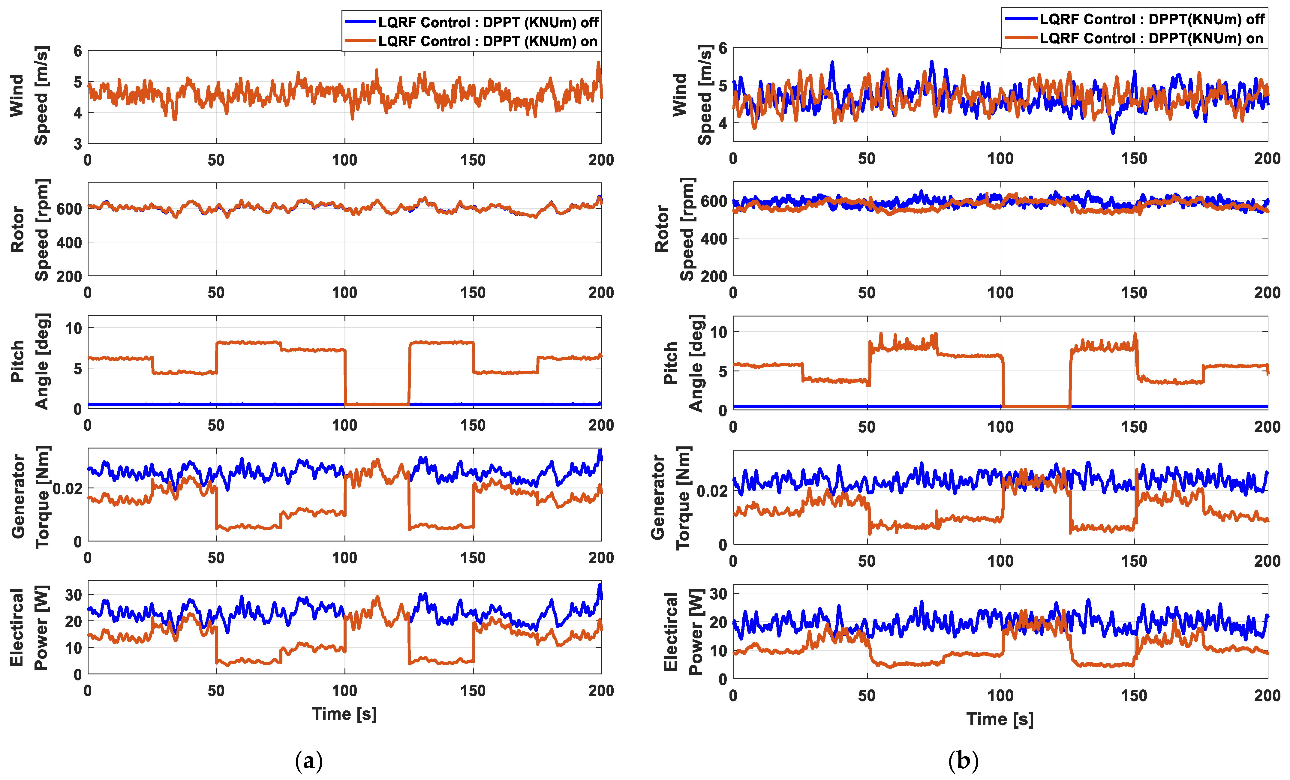
Figure 10 shows the results and of the simulation and the wind tunnel experiment for the proposed DPPT control algorithm for an MIMO controller at an average wind speed of 4.6 m/s. Both the simulation and wind tunnel experiment were implemented in situations wherein 60%-80%-20%-40%-100%-20%-80%-60% power commands were transmitted from the wind farm controller at intervals of 25 s, for a total operation time of 200 s. The sequence of power commands was arbitrarily selected in order to verify the tracking performance of the proposed control algorithm. The windows of the simulation results in Figure 10 represent wind speed, rotor speed, blade pitch angle, generator torque, and electrical power, respectively. 
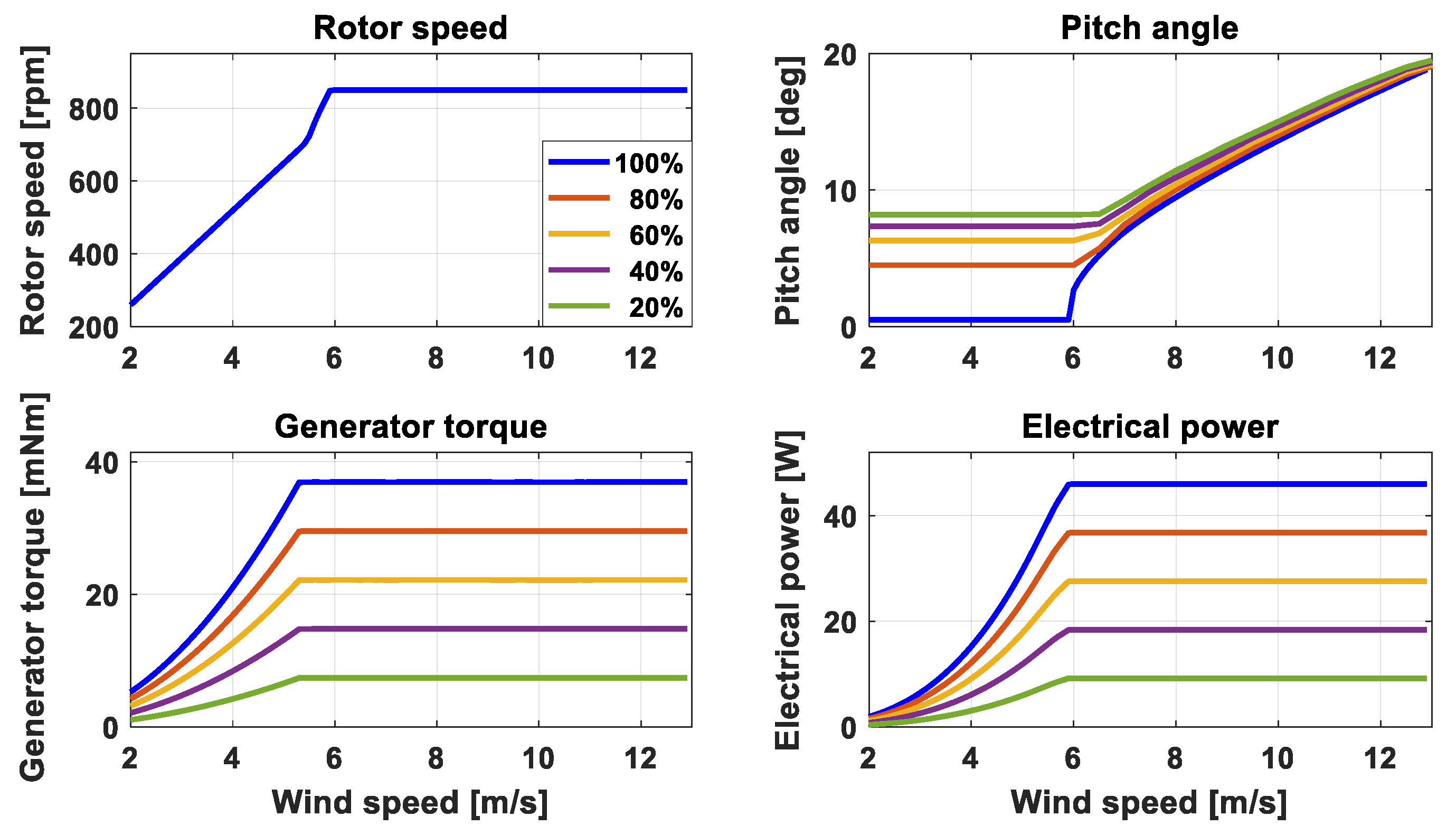
Figure 10a shows the dynamic simulation results of the proposed control algorithm for an average wind speed of 4.6 m/s. It was confirmed that DPPT control occurred while maintaining the rotor speed according to the DPPT B strategy, as shown in Figure 4. Additionally, it was confirmed that, as the demanded power decreased, the pitch angle used increased to a value as high as the delta pitch angle in Figure 5, and the torque became as low as the partialization factor. Figure 10b shows the results of the wind tunnel experiment with the proposed control algorithm for an average wind speed of 4.6 m/s. In the wind tunnel experiments, the same winds were not re-implemented in the time series, so the experiment was performed twice with the same average wind speed (4.6 m/s) at the same turbulence intensity (10%). However, as in the simulation results, it was confirmed that the same rotor speed level was maintained in accordance with the DPPT B strategy, and the pitch angle and torque control were performed to track the power command. Additionally, high-frequency components were observed for most signals owing to the influence of measurement noise, which was absent in the simulation results.
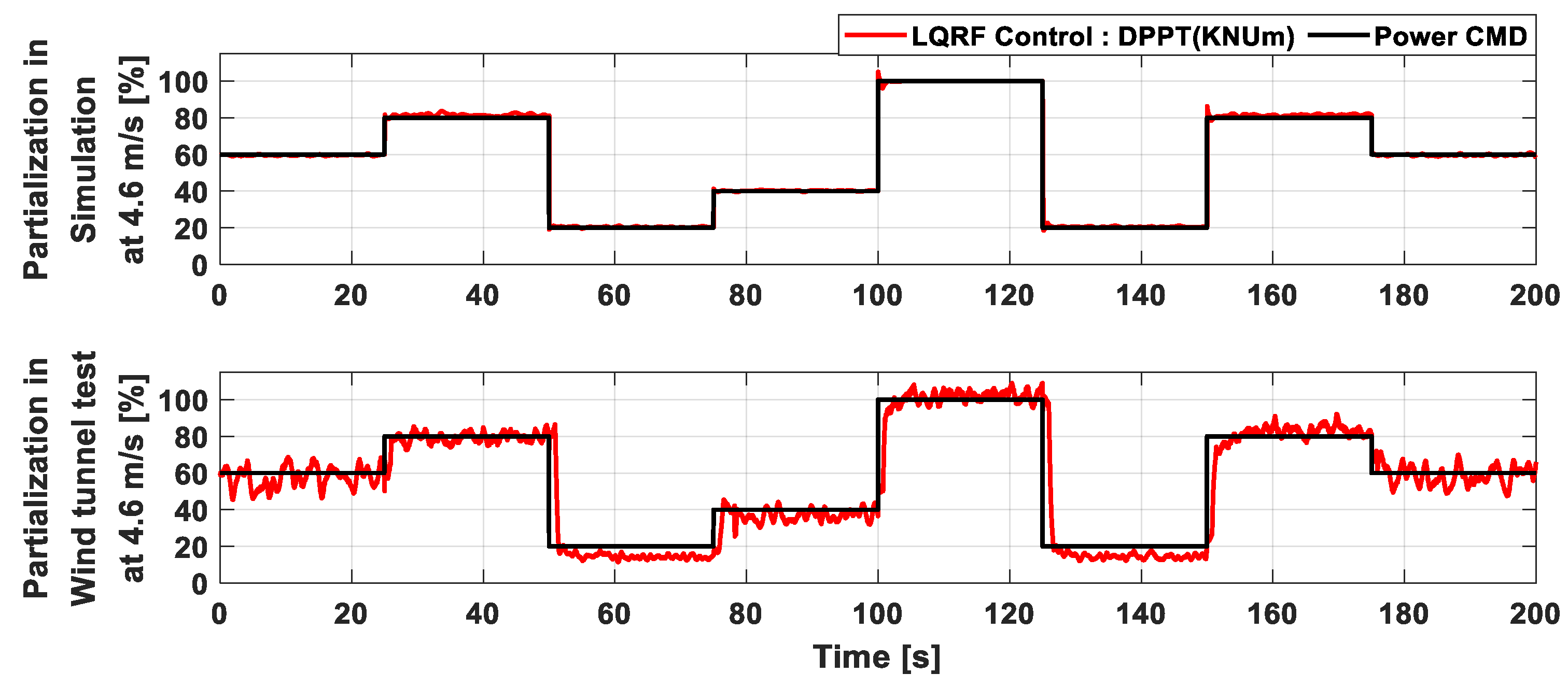
The power commands and controlled power results are shown in Figure 11 can be used to closely check the tracking performance of the proposed DPPT control algorithm. The controlled results indicate that the percentage of the power divided by the available power is comparable to the power commands. The simulation and wind tunnel test results indicate that the power commands were well tracked, but the wind tunnel test results showed increased tracking deviation. These differences appear to stem from the measurement noise generated from experiments and the uncertainty in numerical modeling. Additionally, in some cases where the power command is delivered in Figure 10, the rotor speed decreases slightly. As a result, the power in Figure 11 also decreases slightly. Since simulations always feature more ideal conditions than those found in experiments, the operating conditions of the wind turbine may differ slightly between the simulations and wind tunnel experiments. However, these differences did not significantly affect the performance of wind turbines, and the overall result is that the power commands from the controller were properly tracked.
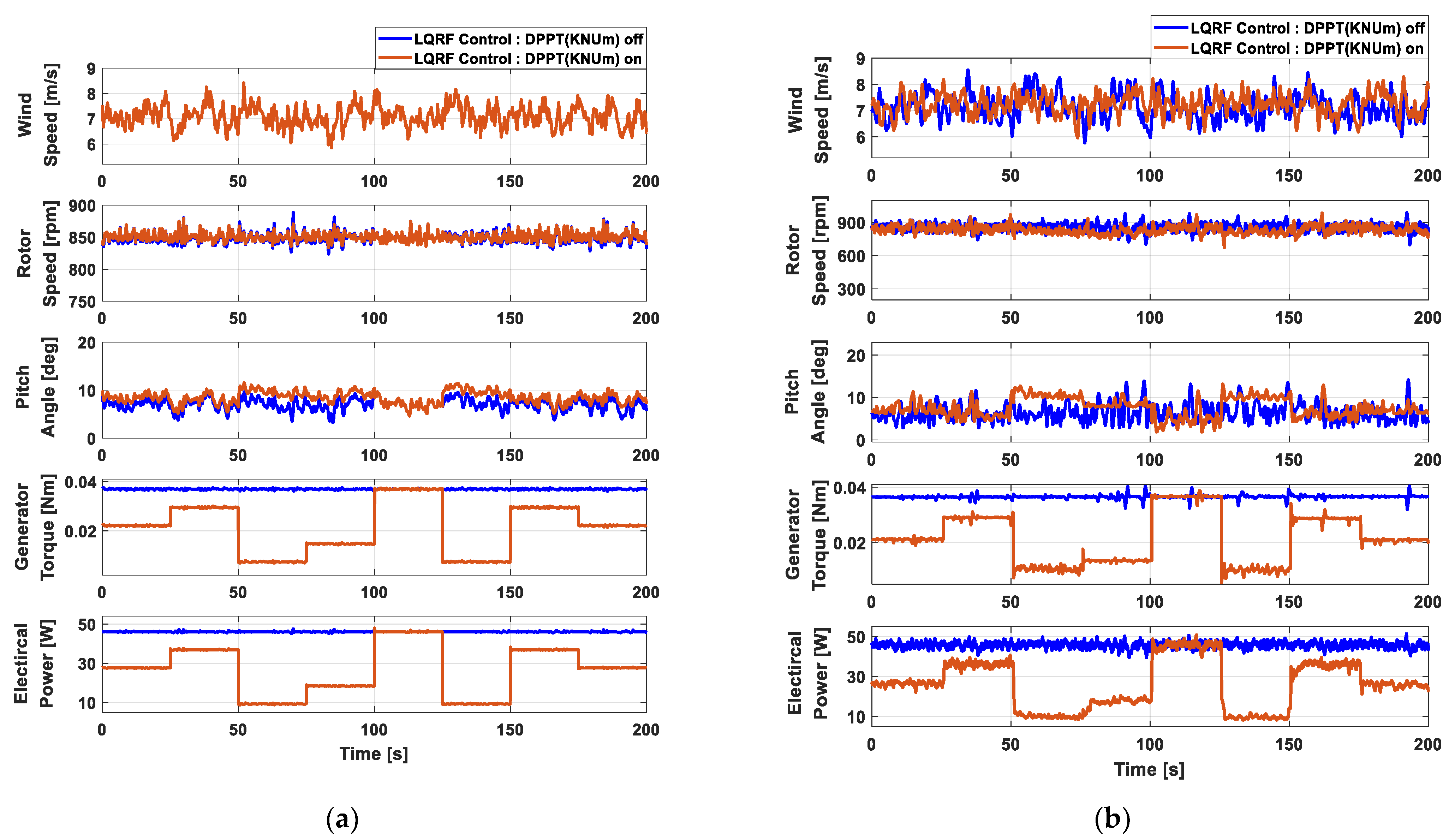
Figure 12 shows the results of the simulation and wind tunnel experiment for the proposed DPPT control algorithm for the MIMO controller at an average wind speed of 7.3 m/s. The same power commands were sent as in the simulation shown in Figure 10, for a total duration of 200 s. Figure 12a shows the results of the dynamic simulation of the proposed control algorithm at an average wind speed of 7.3 m/s. The strategic characteristics of the DPPT B strategy shown in Figure 10a are the same as those shown in Figure 12a. While maintaining the rotor speed in order to track the demanded power point, it was confirmed that the pitch angle was as high as the delta pitch angle and the torque was as low as the partialization factor. Figure 12b shows the results of the wind tunnel experiment for the proposed control algorithm at an average wind speed of 7.3 m/s. Similar measurement noise was observed as in Figure 10b.
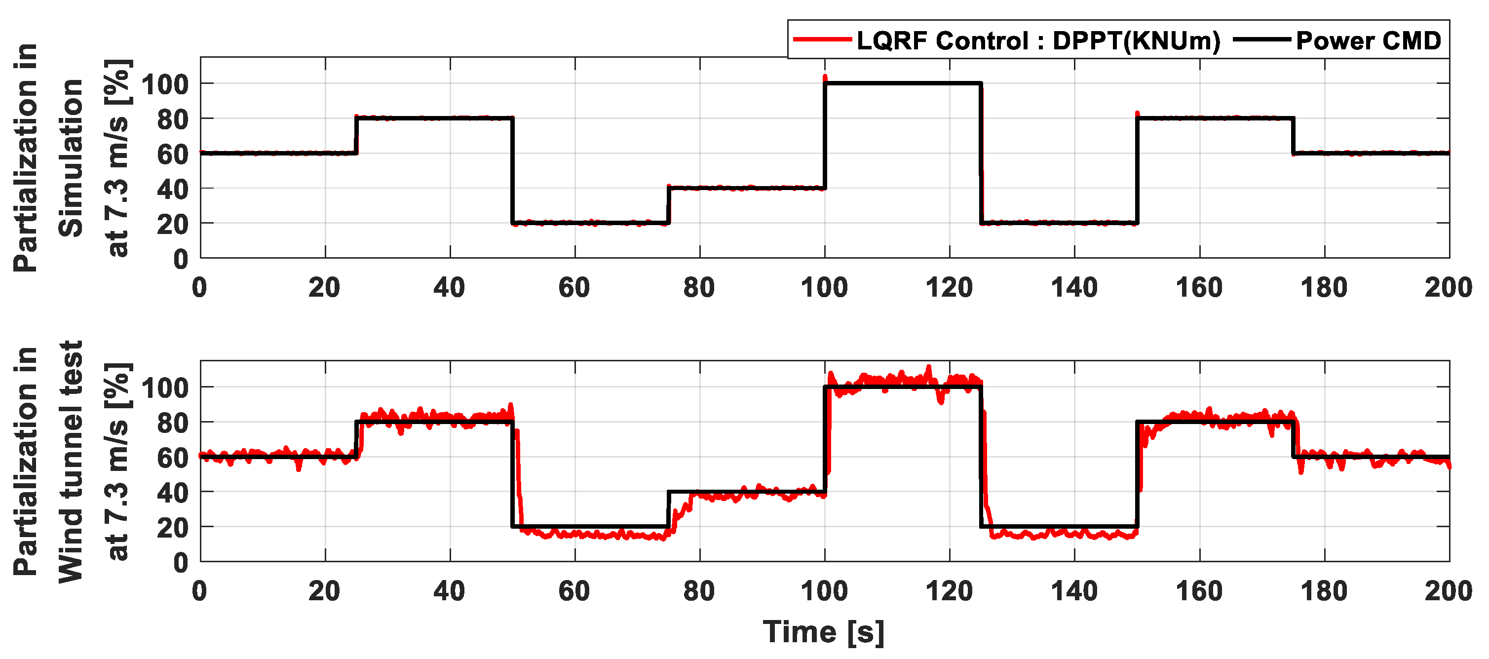
Figure 13 is presented to closely check the tracking performance of the proposed control algorithm, which is shown in Figure 12. Overall, the results in Figure 12 and Figure 13 were found to track the power commands more clearly than the results in Figure 10 and Figure 11. This difference is due to the strategy of tracking the maximum power point, which minimizes the pitch control in Figure 10 (region 2). As a result, the overall control performance of the proposed DPPT control algorithm was found to be suitable for all regions.

5. Discussion

In this study, the proposed control algorithm (KNUm) was compared with the previously studied DPPT algorithm (KNU2) for the classical control algorithm, in order to further analyze the improved performance and validity of the proposed control algorithm through a dynamic simulation [17,18]. The KNU2 control algorithm was previously validated through wind tunnel experiments using a scaled wind turbine. The KNU2 control algorithm is a DPPT control algorithm based on the DPPT strategy for use as a conventional PI control algorithm, and its validity was authenticated by conducting field tests using a medium wind turbine. Additionally, owing to its ease of accessibility, it can be easily implemented as a valid control algorithm. Therefore, the KNU2 control algorithm was adopted as a target for a comparative validation of the validity and improved control performance of the proposed control algorithm in this study.
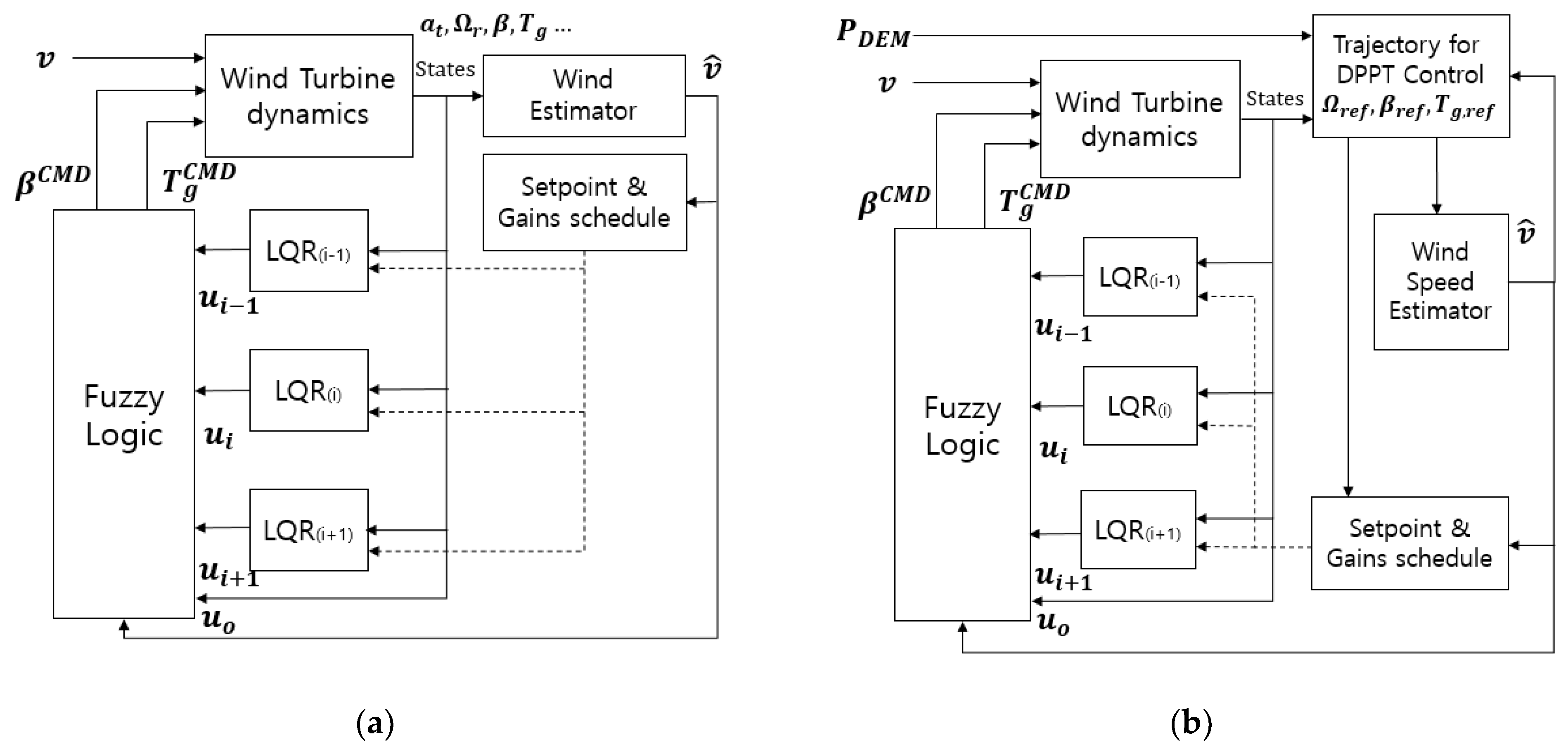
Figure 14 shows the block diagram of the classical control algorithm and the classical control-type DPPT control algorithm, which was studied previously. Figure 14a represents a classic PI control algorithm. Based on the power control strategy shown in Figure 3, pitch PI control and scheduled torque control are performed by a mode switch action. Figure 14b shows the addition of the DPPT control algorithm to Figure 14a. A look-up table was applied in order to output the reference rotor speed as the input of the power command from the wind farm controller. The mode switch and torque control conditions were modified for DPPT control [17].
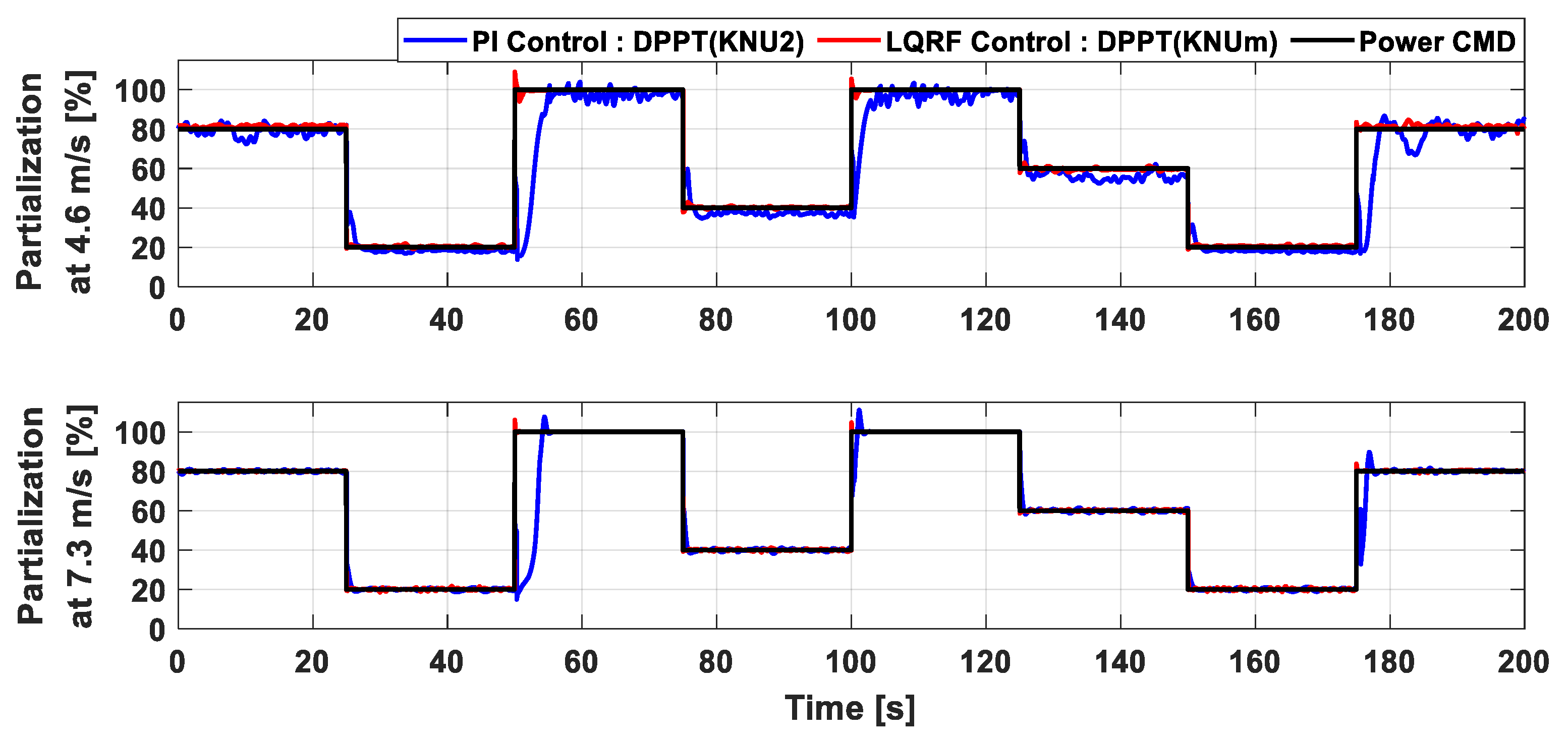
Figure 15 shows the comparative results of the dynamic simulation using the DPPT controller with the classical control algorithm (KNU2) and the modern control algorithms (KNUm) at mean wind speeds of 4.6 and 7.3 m/s. The simulation was implemented by transmitting 80%-20%-100%-40%-100%-60%-20%-80% power commands from the wind farm controller at intervals of 25 s. The sequence of power commands was arbitrarily re-selected to verify the tracking performance of the designed control algorithms. Figure 15a shows the simulation results obtained under a turbulence intensity of 10% and an average wind speed of 4.6 m/s. The DPPT control algorithms of the PI and LQRF controllers were compared using the simulation results, depending on the transmission of power commands from the wind farm controller. It was confirmed that the pitch angles were used more when using the KNU2 controller with the DPPT A strategy than when using the KNUm controller with the DPPT B strategy, as shown in Figure 4. As a result, at approximately 50, 100, and 175 s, the time required to track the required power command slowed down each time the power command changed, due to the rotor speed slowing down or increasing rapidly. Furthermore, because the rotor speed was reduced by the use of several pitch angles when using the KNU2 controller, it was confirmed that a lower torque was required in order to track the power commands. Figure 15b shows the simulation results under a wind turbulence intensity of 10% and an average wind speed of 7.3 m/s. Overall, the characteristics according to the DPPT strategy were similar to those shown in Figure 15a, but were found to be more pronounced. As illustrated in Figure 12, this occurs because the available power in region 3 becomes constant at the rated power, resulting in pitch control to control it.
The numerical comparison results of the simulation are given in Table 3. To understand the structural stability of wind turbines and the state of stable power production, the mean and standard deviation for the rotor speed and power, and tower fore-aft vibration, were selected as the indicators for evaluating the performance of the proposed controller. Compared to the PI control in the situation where the DPPT was off, torque and pitch control were performed by the LQRF algorithm whenever the deviation was likely to be severe, considering the rotor speed and tower vibration deviation. As a result, the rotor speed deviation was reduced by 23.44%, the power deviation by 41.83%, and the tower vibration by 17.24% at an average wind speed of 7.3 m/s. At an average wind speed of 4.6 m/s, not only is it important to reduce the standard deviation, but also to track the maximum power point by the power strategy, so the effect of reducing the deviation was less than at an average wind speed of 7.3 m/s. In the situation where the DPPT was on, the mean rotor speed and tower vibration increased owing to the use of a smaller pitch angle by the KNUm strategy compared to the KNU2 strategy. On the other hand, the standard deviation of the rotor speed and the tower vibration was reduced due to the control performance of the LQRF control and the KNUm strategy of maintaining the same rotor speed level according to the demanded power command.
The power commands and controlled power results in Figure 15 are shown in Figure 16 to compare the tracking performance of the two DPPT control algorithms. The tracking performance of the two control algorithms was found to be better in region 3 (7.3 m/s) than in region 2 (4.6 m/s), similar to the result in Figure 13. Although the KNUm control algorithm used a lower pitch angle than KNU2, it maintained a constant rotor speed, increasing the stability of the control system relative to the rotor speed. As a result, the control performance and suitability of the proposed DPPT control algorithm were acceptable.
Table 4 shows a quantitative comparison of the tracking performance of the two DPPT control algorithms for the demanded power in Figure 16. The tracking performance was evaluated using the mean absolute error (MAE) and the mean square error (MSE) for the demanded power command. Overall, the KNUm controller had a lower error than the KNU2 controller. In region 2, the difference was up to approximately 4.3% for the MAE and up to approximately 10.4% for the MSE. In region 3, the difference was up to approximately 1.8% for the MAE and up to approximately 8.8% for the MSE.

6. Conclusions

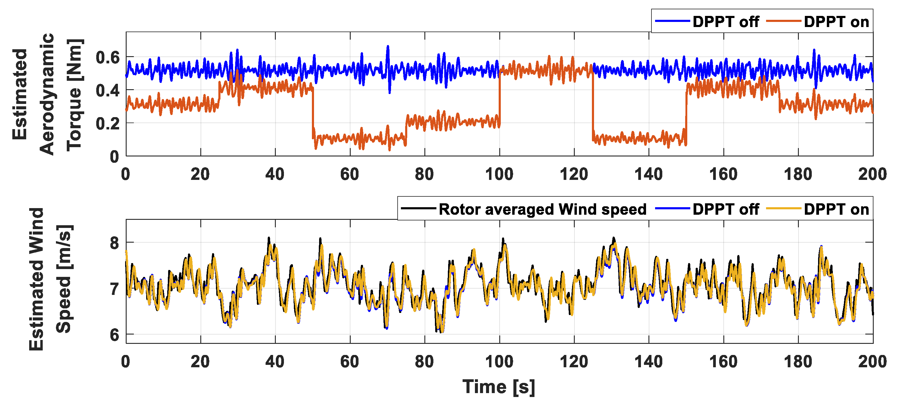
In this study, a DPPT controller was designed for use with a MIMO-type modern control algorithm. The proposed DPPT control algorithm was implemented without mode switches by using multiple reference trajectory. The LQRF control algorithm using wind speed estimators was selected as the target MIMO-type modern control algorithm. The validity of the use of wind-speed estimators for the DPPT algorithms was examined. Although low aerodynamic torque occurred due to DPPT control action, the normal wind speed was maintained because of the reduced torque coefficient stemming from the pitch angle use.
Dynamic simulations and wind tunnel experiments were performed using a scaled wind turbine to validate the proposed control algorithm. Average wind speeds of 4.6 m/s and 7.3 m/s, corresponding to region 2 and region 3, were applied with a turbulence intensity of 10%. Overall, the tracking performance in region 3 was superior to that in region 2, which was attributed to differences in pitch control between the regions based on different power control strategies. In the wind tunnel experiments, variations tended to increase more than in the simulations because of measurement noise and uncertainty problems in numerical modeling. However, both sets of results showed satisfactory tracking performance for demand power commands from the wind farm controllers.
The control performance of the proposed DPPT control algorithm (KNUm) for the MIMO controller was compared with the performance of a previously studied classical control-type DPPT control algorithm (KNU2) through dynamic simulations. KNU2 control algorithms used strategies that produced significant wake deficit effects, although they tended to increase their tracking response time due to the rapid change in rotor speed caused by the use of large pitch angles. The KNUm control algorithm used relatively small pitch angles, but the rotational speed level was preserved. That is, by ensuring the stability of the LQRF control algorithm, rapid tracking response times were achieved and the transient response of the pitch angle was reduced. Specifically, the proposed DPPT control algorithm was confirmed to be suitable for operating the MIMO-type control algorithm.
Overall, this study conducted dynamic simulations and wind tunnel experiments to authenticate the validity, applicability, and tracking performance of the proposed KNUm control algorithm. However, a compromise or optimization problem remains when trying to simultaneously optimize the wake reduction performance and the stability of the control system. Therefore, further studies should be conducted on how to optimize the reference trajectory for power commands. Optimization problems may be studied in conjunction with wind farm control algorithms using machine learning techniques and aerodynamic data from the target wind turbines. Additionally, a study on the control of wind farms using various MIMO-type modern control algorithms could be conducted based on the work presented in this study.

Author Contributions

Conceptualization, T.J., D.K. and Y.S.; Methodology, T.J.; Software, T.J.; Supervision, I.P.; Validation, T.J. and D.K.; Writing—original draft, T.J.; Writing—review & editing, I.P. All authors have read and agreed to the published version of the manuscript.

Funding

This work was supported by the Energy Efficiency & Resources Program and the New and Renewable Energy-Core Technology Program of the Korea Institute of Energy Technology Evaluation and Planning (KETEP) with a grant of financial resources from the Ministry of Trade, Industry and Energy, Republic of Korea (Grants Nos. 20203040020120 and 20204030200010).

Institutional Review Board Statement

Not applicable.

Informed Consent Statement

Not applicable.

Data Availability Statement

Not applicable.

Conflicts of Interest

The authors declare no conflict of interest.

References

  1. Manwell, J.F.; Mcgowan, J.G.; Rogers, A.L. Wind Energy Explained, 2nd ed.; John Wiley & Sons Ltd.: Hoboken, NJ, USA, 2009. [Google Scholar]
  2. Dixit, A.; Suryanarayanan, S. Towards pitch-scheduled drive train damping in variable-speed, horizontal-axis latge wind turbines. In Proceedings of the 44th IEEE Conference on Decision and Control, Seville, Spain, 12–15 December 2005; pp. 1295–1300. [Google Scholar]
  3. Kim, C.; Kim, K.; Paek, I. Design of tower damper gain scheduling algorithm for wind turbine tower load reduction. J. Korean Sol. Energy Soc. 2018, 38, 1–13. [Google Scholar]
  4. Kim, K.; Kim, H.; Kim, H.; Son, J.; Kim, J.; Park, J. Resonance Avoidance Control Algorithm for Semi-Submersible Floating Offshore Wind Turbine. Energies 2021, 14, 4138. [Google Scholar] [CrossRef]
  5. Kim, K.; Kim, H.-G.; Paek, I. Application and Validation of Peak Shaving to Improve Performance of a 100 KW Wind Turbine. Int. J. Precis. Eng. Manuf. Green Technol. 2020, 7, 411–421. [Google Scholar] [CrossRef]
  6. Nam, Y.; Kim, J.; Paek, I.; Mun, Y.; Kim, S.; Kim, D. Feedforward pitch control using wind speed estimation. J. Power Electron. 2011, 11, 211–217. [Google Scholar] [CrossRef]
  7. Chaoui, H.; Miah, S.; Oukaour, A.; Gualous, H. Maximum Power Point Tracking of Wind Turbines with Neural Networks and Genetic Algorithms. In Proceedings of the IECON 2014—40th Annual Conference of the IEEE Industrial Electronics Society, Dallas, TX, USA, 29 October 2014; IEEE: Dallas, TX, USA, 2014; pp. 197–201. [Google Scholar]
  8. Pham, T.; Nam, Y.; Kim, H.; Son, J. LQR control for a multi-MW wind turbine. World Acad. Sci. Eng. Technol. 2012, 62, 670–675. [Google Scholar]
  9. Christiansen, S.; Knudsen, T.; Bak, T. Optimal Control of a Ballast-Stabilized Floating Wind Turbine. In Proceedings of the 2011 IEEE International Symposium on Computer-Aided Control System Design (CACSD), Denver, CO, USA, 28–30 September 2011; IEEE: Denver, CO, USA, 2011; pp. 1214–1219. [Google Scholar]
  10. Barcena, R.; Acosta, T.; Etxebarria, A.; Kortabarria, I. Wind Turbine Structural Load Reduction by Linear Single Model Predictive Control. IEEE Access 2020, 8, 98395–98409. [Google Scholar] [CrossRef]
  11. Jeon, T.; Paek, I. Design and Verification of the LQR Controller Based on Fuzzy Logic for Large Wind Turbine. Energies 2021, 14, 230. [Google Scholar] [CrossRef]
  12. de Corcuera, A.D.; Pujana-Arrese, A.; Ezquerra, J.M.; Segurola, E.; Landaluze, J. H∞ Based Control for Load Mitigation in Wind Turbines. Energies 2012, 5, 938–967. [Google Scholar] [CrossRef] [Green Version]
  13. Jeon, T.; Kim, D.; Paek, I. Design and Analysis of yaw command tracking control algorithm for wind turbine for wind farm control application. J. Korean Sol. Energy Soc. 2021, 41, 65–78. [Google Scholar]
  14. Siniscalchi-Minna, S.; Bianchi, F.D.; De-Prada-Gil, M.; Ocampo-Martinez, C. A Wind Farm Control Strategy for Power Reserve Maximization. Renew. Energy 2019, 131, 37–44. [Google Scholar] [CrossRef]
  15. Kim, H.; Kim, K.; Paek, I. Power Regulation of Upstream Wind Turbines for Power Increase in a Wind Farm. Int. J. Precis. Eng. Manuf. 2016, 17, 665–670. [Google Scholar] [CrossRef]
  16. Jeong, Y.; Johnson, K.; Fleming, P. Comparison and Testing of Power Reserve Control Strategies for Grid-Connected Wind Turbines: Power Reserve Control for Grid-Connected Wind Turbines. Wind Energ. 2014, 17, 343–358. [Google Scholar] [CrossRef]
  17. Kim, K.; Kim, H.-G.; Kim, C.; Paek, I.; Bottasso, C.L.; Campagnolo, F. Design and Validation of Demanded Power Point Tracking Control Algorithm of Wind Turbine. Int. J. Precis. Eng. Manuf. Green Technol. 2018, 5, 387–400. [Google Scholar] [CrossRef]
  18. Kim, K.; Kim, H.; Paek, I.; Kim, H.-G.; Son, J. Field Validation of Demanded Power Point Tracking Control Algorithm for Medium-Capacity Wind Turbine. Int. J. Precis. Eng. Manuf. Green Technol. 2019, 6, 875–881. [Google Scholar] [CrossRef]
  19. Bottasso, C.L.; Campagnolo, F. Wind Turbine and Wind Farm Control Testing in a Boundary Layer Wind Tunnel. In Proceedings of the 32nd ASME Wind Energy Symposium, National Harbor, MD, USA, 13–17 January 2014; American Institute of Aeronautics and Astronautics: National Harbor, MD, USA, 2014. [Google Scholar]
  20. Campagnolo, F.; Petrovic, V.; Nanos, E.M.; Tan, C.W.; Bottasso, C.L.; Paek, I.; Kim, H.; Kim, K. Wind tunnel testing of power maximization control strategies applied to a multi-turbine floating wind power platform. In Proceedings of the 26th International Ocean and Polar Engineering Conference, ISOPE-I-16-307, Rhodes, Greece, 26 June–2 July 2016. [Google Scholar]
  21. Kim, D.; Paek, I.; Won, B.; Jeon, T. Performance Test of 3D Printed Blades for a Scaled Wind Turbine in a Wind Tunnel. KSPE 2020, 37, 707–715. [Google Scholar] [CrossRef]
  22. Bottasso, C.L.; Campagnolo, F.; Petrović, V. Wind tunnel testing of scaled wind turbine models: Beyond aerodynamics. J. Wind Eng. Ind. Aerodyn. 2014, 127, 11–28. [Google Scholar] [CrossRef]
  23. Kim, H.; Kim, K.; Bottasso, C.; Campagnolo, F.; Paek, I. Wind Turbine Wake Characterization for Improvement of the Ainslie Eddy Viscosity Wake Model. Energies 2018, 11, 2823. [Google Scholar] [CrossRef] [Green Version]
Figure 1. Image of scaled wind turbine.
Energies 14 05818 g001
Figure 2. Flowchart of design and validation for MIMO controller with DPPT.
Energies 14 05818 g002
Figure 3. Power control strategy for wind turbines.
Energies 14 05818 g003
Figure 4. Example of power derating strategy. (a) Effect on power coefficients; (b) effect on thrust coefficients.
Energies 14 05818 g004
Figure 5. Three-dimensional (3D) plotting of delta pitch angle.
Energies 14 05818 g005
Figure 6. Reference trajectory according to the partialization.
Energies 14 05818 g006
Figure 7. Block diagram of control algorithms. (a) LQRF control algorithm; (b) LQRF control algorithm with DPPT control.
Energies 14 05818 g007
Figure 8. Simulation results of aerodynamic torque and wind speed estimated by wind speed estimator.
Energies 14 05818 g008
Figure 9. View of wind tunnel experiments.
Energies 14 05818 g009
Figure 10. Simulation and wind tunnel experiments results of DPPT control algorithm for MIMO controller with a turbulent wind speed of 4.6 m/s. (a) Dynamic simulation; (b) wind tunnel experiment.
Energies 14 05818 g010
Figure 11. Simulation and wind tunnel experiment results for power command tracking performance at a wind speed of 4.6 m/s.
Energies 14 05818 g011
Figure 12. Simulation and wind tunnel experiment results of DPPT control algorithm for MIMO controller using a turbulent wind speed of 7.3 m/s. (a) Dynamic simulation; (b) wind tunnel experiment.
Energies 14 05818 g012
Figure 13. Simulation and wind tunnel experiment results for power command tracking performance at a wind speed of 7.3 m/s.
Energies 14 05818 g013
Figure 14. Block diagram of control algorithms. (a) Conventional PI control algorithm; (b) PI control algorithm with DPPT control.
Energies 14 05818 g014
Figure 15. Dynamic simulation results for the comparison of KNU2 and KNUm control algorithms. (a) Average wind speed of 4.6 m/s; (b) average wind speed of 7.3 m/s.
Energies 14 05818 g015
Figure 16. Simulation results for power command tracking performance at wind speeds of 4.6 and 7.3 m/s.
Energies 14 05818 g016
Table 1. Specifications of target wind turbine.
SpecificationsUnitsValues
Rotor diameterm1.1
Hub heightm0.9
Gear ratio-14
Fine pitch angledeg0.5
Rated rotor torqueNm0.517
Rated electrical powerW46
Rated rotor speedrpm850
Cut-in, rated, cut-out wind speedm/s3, 6, 13
Table 2. Reference trajectory planning for DPPT control.
ClassificationTrajectory Planning for Reference
Ω ref   ( v ) β ref   ( v ) T ref   ( v )
Region 2 λ R v [ β f i n e such that: C P m a x ( λ , β ) ] +   δ β ( p , v ) p · 1 2 ρ π R 3 v 2 · C P m a x ( λ , β ) λ
Region 3 Ω r a t e d [ β such that: 1 2 ρ π R 2 v 3 C P ( λ , β ) = P r a t e d ] +   δ β ( p , v ) p · P r a t e d Ω r a t e d
Table 3. Performance data for the comparison of KNU2 and KNUm control algorithms.
Performance DataMeanStd. Dev.
Ω r   ( rpm ) P   ( W ) d   ( mm ) Ω r   ( rpm ) P   ( W ) d   ( mm )
Region 2
(4.6 m/s)
KNU2 off (A)593.15922.7480.12131.8273.6560.018
KNU2 on (B)479.00413.4620.048104.0077.3780.048
KNUm off (C)601.49222.6850.12229.1123.8730.016
KNUm on (D)601.82014.3840.06229.6787.4030.044
DPPToff(C−A)/A (%)1.405−0.2770.826−8.530−5.603−11.111
on(D−B)/B (%)25.6406.84929.167−71.4650.339−8.333
Region 3
(7.3 m/s)
KNU2 off (E)849.49945.9930.14712.1830.6000.029
KNU2 on (F)639.48228.1210.082149.98414.0270.056
KNUm off (G)848.96246.0130.1479.3270.3490.024
KNUm on (H)849.85728.7900.0999.11914.1340.041
DPPToff(G−E)/E (%)−0.0630.0450.000−23.443−41.833−17.241
on(H−F)/F (%)32.8982.37920.732−93.9200.763−26.786
Table 4. Quantitative comparison of tracking performance.
ComparisonRegion 2 (4.6 m/s)Region 3 (7.3 m/s)
MAE   ( % ) MSE   ( % ) MAE   ( % ) MSE   ( % )
KNU25.02511.8302.0909.851
KNUm0.7191.4560.2551.103
Publisher’s Note: MDPI stays neutral with regard to jurisdictional claims in published maps and institutional affiliations.

