Article

Modelling Types 1 and 2 Wind Turbines Based on IEC 61400-27-1: Transient Response under Voltage Dips

by
Tania García-Sánchez
1,†,
Irene Muñoz-Benavente
2,†,
Emilio Gómez-Lázaro
3,† and
Ana Fernández-Guillamón
2,*,†
1
Department of Electrical Engineering, Universitat Politècnica de València, 46022 Valencia, Spain
2
Department of Automatics, Electrical English and Electronic Technology, Universidad Politécnica de Cartagena, 30202 Cartagena, Spain
3
Renewable Energy Research Institute and DIEEAC-EDII-AB, Universidad de Castilla-La Mancha, 02006 Albacete, Spain
*
Author to whom correspondence should be addressed.
These authors contributed equally to this work.
Energies 2020, 13(16), 4078; https://doi.org/10.3390/en13164078
Submission received: 22 June 2020 / Revised: 23 July 2020 / Accepted: 4 August 2020 / Published: 6 August 2020
(This article belongs to the Special Issue Real-Time Monitoring and Control for Wind Turbine Systems)

Abstract

:
Wind power plants depend greatly on weather conditions, thus being considered intermittent, uncertain and non-dispatchable. Due to the massive integration of this energy resource in the recent decades, it is important that transmission and distribution system operators are able to model their electrical behaviour in terms of steady-state power flow, transient dynamic stability, and short-circuit currents. Consequently, in 2015, the International Electrotechnical Commission published Standard IEC 61400-27-1, which includes generic models for wind power generation in order to estimate the electrical characteristics of wind turbines at the connection point. This paper presents, describes and details the models for wind turbine topologies Types 1 and 2 following IEC 61400-27-1 for electrical simulation purposes, including the values for the parameters for the different subsystems. A hardware-in-the-loop combined with a real-time simulator is also used to analyse the response of such wind turbine topologies under voltage dips. The evolution of active and reactive powers is discussed, together with the wind turbine rotor and generator rotational speeds.

1. Introduction

Renewable energy sources can provide an acceptable solution for two important issues related to the electricity supply. They can help to (i) reduce the greenhouse gas emissions; and (ii) mitigate the importation of fuels from other countries [1,2]. Consequently, over recent decades, power systems have slowly been changing, with some traditional power plants (mainly based on fossil and nuclear fuels) being replaced by renewable energy sources generation units [3,4]. Of these, the most widely developed and installed renewable energy sources is wind power [5,6], which accounted for more than 650 GW of installed capacity in 2019 [7] and, in fact, plays an increasingly important role in current power systems [8,9]. Wind turbines (WTs) are generally divided into fixed speed wind turbines (FSWTs) and variable speed wind turbines (VSWTs). The difference between FSWTs and VSWTs is that FSWTs always work at the same rotational speed (regardless of wind speed), whereas VSWTs can modify their rotational speed in order to follow the optimum power point for each wind speed. To overcome this, VSWTs use a partial or full additional power converter, in contrast to FSWTs, which are directly connected to the grid [10]. Moreover, WTs present different topologies depending on their generator [11]: Type 1, which includes a squirrel cage induction generator with fixed rotor resistance; Type 2, which includes a wound rotor induction generator with variable rotor resistance; Type 3, which includes a doubly-fed induction generator with a partial-scale converter; and Type 4, which includes a synchronous generator with a full-converter [12]. Types 1 and 2 are FSWTs, whereas Types 3 and 4 are VSWTs, as shown in Figure 1.
However, wind power plants depend on weather conditions, more precisely on turbulent wind speed [13], thus being intermittent and uncertain [14,15]. In fact, they are commonly referred to as ‘non-dispatchable’ sources [16]. In consequence, they place stress on the grid, as both transmission and distribution system operators have to deal not only with the uncontrollable demand, but also uncontrollable generation [17]. Thus, it is important for transmission and distribution system operators to be able to model the behaviour of WTs and wind power plants, especially in terms of steady-state power flow, transient dynamic stability, and short-circuit current [18]. Traditionally, both WTs and wind power plants’ models were represented by manufacturer specific models, which required a large number of parameters [19]. However, in February 2015, the International Electrotechnical Commission (IEC) published Standard IEC 61400-27-1, which included generic models for the four topologies of WTs presented in Figure 1 [20]. As a result, these models can be used to simulate WTs integrated in the grid with any specific software [21]. Actually, second edition of IEC 61400-27 ‘Wind energy generation systems—Part 27-1: Electrical simulation models—Generic models’ and first edition of IEC 61400-27 ‘Wind energy generation systems—Part 27-2: Electrical simulation models—Model validation’ are in final draft international standard stage, being approved by IEC National Committees in June 2020.
In this work, the generic Types 1 and Types 2 WTs models described in IEC 61400-27-1 are simulated and tested facing a three-phase voltage dip based on a hardware-in-the-loop (HIL) together with a real-time simulator. The main objective of this paper is to deeply describe such wind turbines models following the IEC 61400-27-1 and by the use of Matlab/Simulink environment. In this way, it is possible to help researchers with different backgrounds to better understand the electrical modelling of Types 1 and Types 2 wind turbines, together with their behaviour under voltage dips. A voltage dip is a short reduction of the voltage amplitude below a given threshold in one or more phases [22], where a three-phase voltage dip represents the worst-case scenario. Even though their duration is less than 1 s, voltage dips cause most of the problems related to voltage quality [23]. Different events such as short circuits or earth faults can cause significant voltage dips [24]. A voltage dip is typically expressed in terms of the lost voltage and its duration, as depicted in Figure 2, where the X axis is the event duration, and the Y axis is the event magnitude [25].
Different studies have focused on FSWTs, especially on their low-voltage ride-through (LVRT) capability [26,27,28,29,30,31,32,33,34,35,36]. However, none of these works have used the generic models proposed in Standard IEC 61400-27-1. In fact, most of the papers related to the models provided by the IEC are focused on VSWTs [37,38,39,40,41,42,43,44], and there is thus a lack of contributions regarding the FSWTs generic models. This paper aims to fill that gap, by describing and detailing the different subsystems needed to simulate Types 1 and 2 WTs following Standard IEC 61400-27-1. The rest of the paper is organised as follows: Section 2 presents the main elements of Types 1 and 2 WTs according to IEC 61400-27-1; the modelling of the different subsystems is explained and detailed in Section 3; the results of the voltage dip simulations are shown in Section 4; and finally, Section 5 presents the conclusions.

2. IEC 61400-27-1 Types 1 and 2 Wind Turbine Model

FSWTs are electrically simple devices consisting of an aerodynamic rotor which drives a low-speed shaft, a gearbox coupling the WT rotor with the generator, a high-speed shaft and an asynchronous generator [45]. Most FSWTs are equipped with mechanically switched capacitor banks for reactive power compensation [46]. In addition, for fault-ride-through (FRT) purposes, the blade pitch angle may be changed depending on the voltage dip depth, in order to avoid a rapid increase in rotor speed [47]. For this purpose, a thyristor switched capacitor bank is dynamically controlled during and after such faults. To simultaneously disconnect the asynchronous generator and the mechanically switched capacitor from the grid, the model has a main circuit breaker. Moreover, WT terminals can be on either side of the transformer as stated in IEC 61400-21 [48]. As already mentioned, FSWTs include Types 1 and 2 WTs. Figure 3 shows the main electrical and mechanical components of both Types 1 and 2 WTs [49]. Neither a power converter nor any other speed regulation techniques are used in these configurations [50].
Type 1 WTs use a squirrel cage induction (asynchronous) generator [51]. In addition, Type 1 WTs can have either (i) a fixed blade pitch angle, or (ii) a pitch control system to turn the blades away from stall or into stall, which can be used for FRT control. As a result, these WTs are divided into Type 1A (those WTs without FRT capability, i.e., with a fixed blade pitch angle), and Type 1B (those WTs with FRT capability due to the pitch angle control) [52].
Type 2 WTs are equipped with an electronically-controlled variable resistance connected to the rotor winding (VRR) [53]. Therefore, instead of using a squirrel cage asynchronous generator, they need a wound rotor asynchronous generator [54]. The VRR can modify the slip of the generator, with a typical limit of around 10% over the synchronous speed [55]. Moreover, these WTs are usually equipped with pitch angle control [56]. With the combination of both VRR and pitch control, the WT rotor speed can be modified based on the tip speed ratio to achieve a better power output than Type 1 WTs [57].

3. Modelling

Following Standard IEC 61400-27-1, different subsystems should be included to model Types 1 and 2 WTs. The Type 1 is divided into 1A and 1B, depending on the FRT capability, as explained in Section 2. As some of the subsystems are common for the three types of WTs under consideration, they are only explained the first time they appear (i.e., for Type 1A WTs).

3.1. Type 1A WT Model

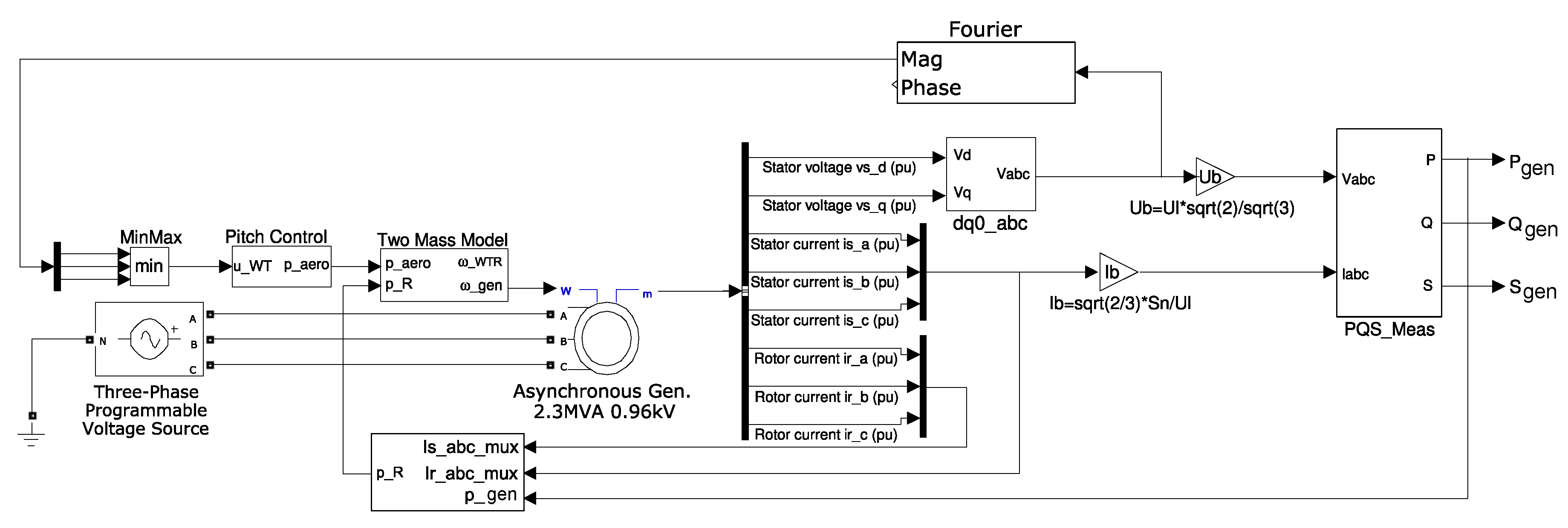
The generic model of the Type 1A WT needs the following subsystems: (i) aerodynamic module, (ii) mechanical model, (iii) generator set model, and (iv) electrical measurements model (active, reactive and apparent power measurements). Figure 4 shows the complete Type 1A WT model. The different parameters of this Type 1A WT are presented in Appendix A, Table A1.

3.1.1. Aerodynamic Module

The aerodynamic module represents a simple constant aerodynamic torque model. This model is only needed in the Type 1A WT. The aerodynamic torque is assumed to be constant for a short initial period of time. As can be seen in Equation (1), the aerodynamic power ( P a e r o ) is obtained by multiplying such initial value of torque ( T i n i t ) by the WT rotor rotational speed ( ω W T R ), where T i n i t must be set by the load-flow:
P a e r o = T i n i t · ω W T R .

3.1.2. Mechanical Model

Following Standard IEC 61400-27-1, the mechanical model is represented by a two-mass model, which considers the rotor as a single mass, and the generator as another mass [58]. Thus, both the low-speed of the WT rotor ( ω W T R ) and the high-speed of the asynchronous generator ( ω g e n ) are represented [59]. In fact, the two different masses (large for the turbine rotor and small for the generator) are linked by a flexible shaft, which is characterised by its stiffness and damping [60]. Subsequently, the acceleration/deceleration of the rotor speed will be followed by the rotational speed of the generator, having periodic fluctuations of speed [61]. Moreover, according to Boukhezzar and Siguerdidjane [62], the use of this mechanical model is enough for transient stability analysis with WT, being thus considered as appropriated to represent their mechanical dynamics [63]. The block diagram for this model is presented in Figure 5.
The main difference between Standard IEC 61400-27-1 and this model is that the integrators are separated from the constants. In this way, initial conditions for the rotational speed ω of the WT rotor and asynchronous generator, as well as the initial torque T i n i t can be specified.
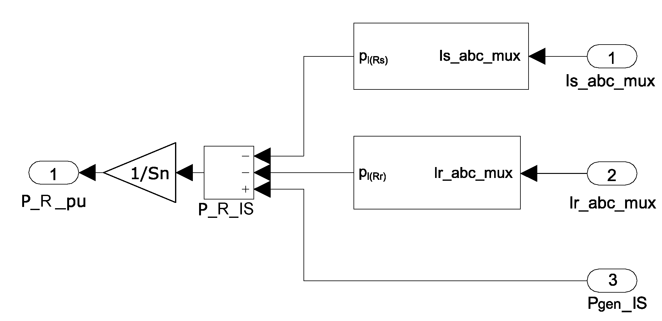
The aerodynamic power ( P a e r o ) directly comes from the aerodynamic module. However, the electrical power ( P R ) is determined as the stator electrical output power plus the power losses in the rotor and stator resistances ( P l ( R s ) and P l ( R r ) , respectively). These P l ( R s ) and P l ( R r ) losses are estimated according to the expression:
P l ( R i ) = 3 · I i · f 2 · R i ,
where P l ( R i ) are the power losses, I are the currents in a, b, c system, f is the system frequency, R is the resistance and subscript i refers to the rotor or stator. The block diagram for determining P g e n is shown in Figure 6, with the stator currents in a, b, c system ( I s , a b c , m u x ) (in A), the rotor currents in a, b, c system ( I r , a b c , m u x ) (in A) and the electrical output power ( P g e n , I S ) (W) as inputs. To obtain the value of P R in pu, the result of P g e n P l ( R s ) P l ( R r ) is divided by the nominal apparent power S n .

3.1.3. Generator Set Model

Standard IEC 61400-27-1 does not specify a model for the asynchronous generator. However, as explained in [64], a third-order generator model is used, in which the stator flux derivatives are neglected. This assumption is common for transient stability simulations [65]. Consequently, the SimPowerSystems block called Asynchronous Machine pu Units was used. As Type 1A WT uses a squirrel cage induction generator and the output from the two-mass model is the generator rotational speed ω g e n , the parameters to be set on the SimPowerSystems block are: (i) nominal power S n ; (ii) voltage line-line U L ; (iii) system frequency f; (iv) stator resistance and inductance R s , L s in pu; (v) rotor resistance and inductance R s , L s in pu; (vi) mutual inductance L m in pu; and (vii) initial conditions. As this generator uses pu units, the base values of voltage and current magnitudes are:
U b = 2 · U L 3 = 2 · U f ,
I b = 2 · I f = 2 · S n 3 · U L = 2 3 · S n U L
By combining Equations (3) and (4):
Z b = U b I b = U L 2 S n .
The asynchronous generator uses the amplitude values of phase current and voltage as base values. Therefore, the base power value is obtained as:
S n S b = 3 · I f I b · U f U b = 3 · I f 2 · I f · U f 2 · U f = 3 2 S b = 3 2 · S n .
These values must be taken into account to obtain the real values of the different magnitudes.

3.1.4. Electrical Measurements Model

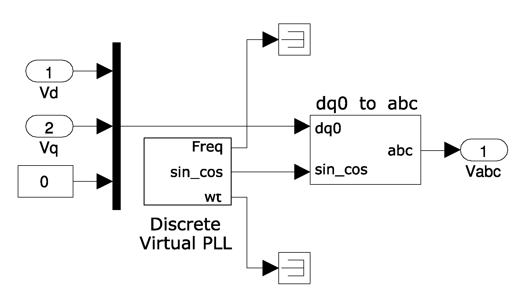
All electrical measurements are obtained from the generator measurement bus m of the Asynchronous Machine pu Units of SymPowerSystems. The values used are the following: (i) stator voltages v s _ d and v s _ q ; (ii) stator currents i s _ a , i s _ b and i s _ c ; and (iii) rotor currents i r _ a , i r _ b and i r _ c . As v s _ d and v s _ q are defined in the dq system, they must be transformed into the a, b, c system as shown in Figure 7.
A 0 vector must be added as a constant. Also a Discrete Virtual PLL block is needed to obtain the s i n _ c o s input of the converter. The block dq0_to_abc Transformation needs no additional parameters. Thus, both v s _ d and v s _ q are defined in the a, b, c system.
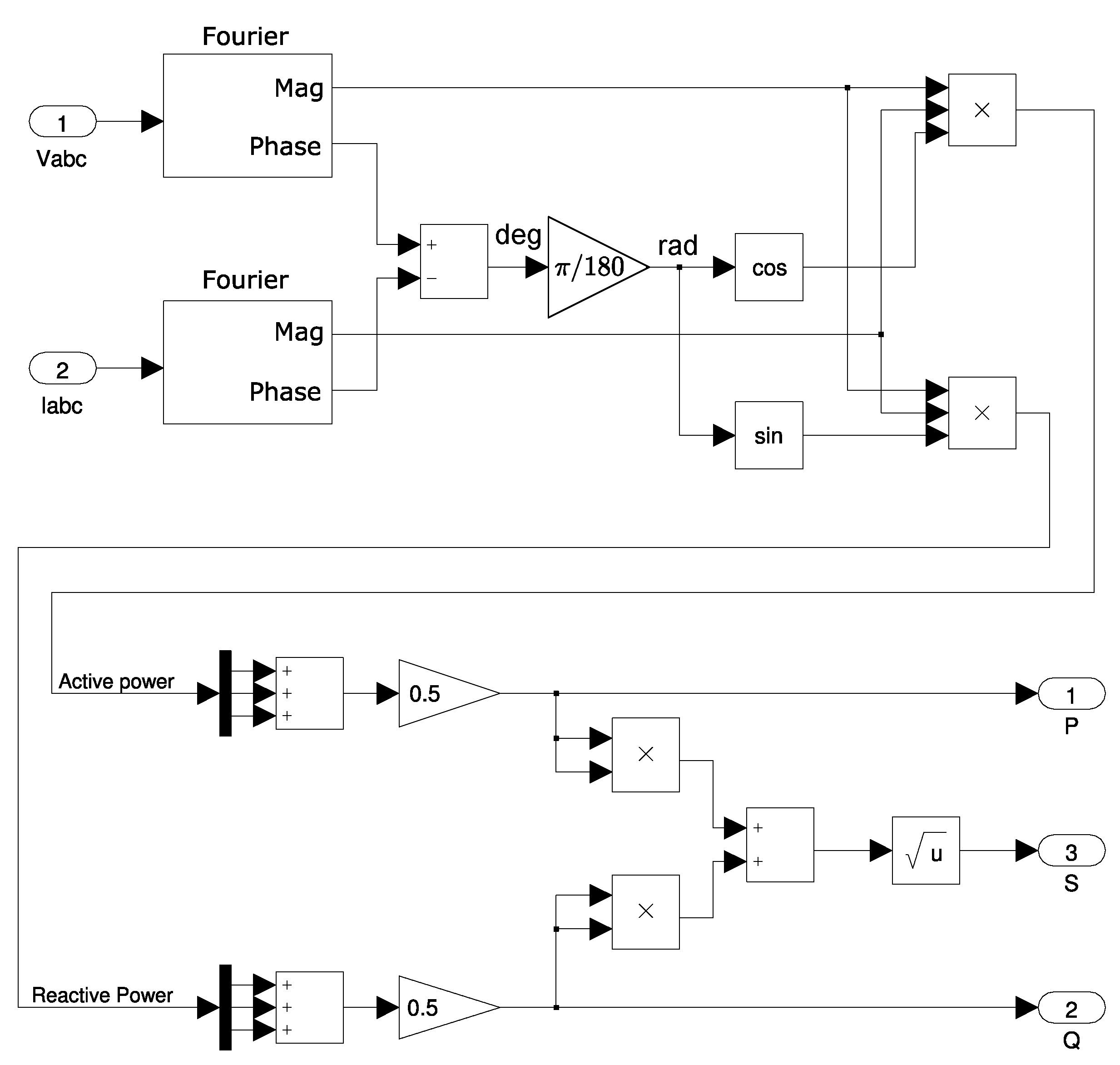
In the following subsystems, the three-phase values of each magnitude are multiplexed to reduce the number of connections needed. The pu magnitudes are multiplied by the pertinent base values (refer to Equations (3)–(6)). Consequently, stator currents and voltages (in the International System units) are the inputs to the subsystem in Figure 8, used to calculate active, reactive and apparent powers.
Fourier blocks provide the peak value of the sinusoidal magnitude of the frequency stated, as well as its phase (in degrees). As we obtain phase values in each channel of the bus, the total active and reactive powers are as follows:
P = j = 1 3 U f j · I f j · c o s ( φ u j φ i j ) ,
Q = j = 1 3 U f j · I f j · s e n ( φ u j φ i j ) .
As can be seen from Figure 8, P and Q values are multiplied by 0.5. As already mentioned, the Fourier blocks provide the peak values, so P and Q (Equations (7) and (8)) are actually multiplied by 2 · 2 = 2 . Then, the Trigonometric function blocks work in radians. Therefore, degrees must be transformed by multiplying the output of the subtraction blocks by π 180 . Finally, apparent power is calculated as:
S = P 2 + Q 2 .

3.2. Type 1B WT Model

Type 1A and 1B WTs differ in the following: (i) Type 1B WTs do not require the aerodynamic model, and (ii) Type 1B WTs have UVRT pitch angle control. Consequently, the mechanical model, generator set model, and electrical measurements model are the same of those previously described for Type 1A WTs (refer to Section 3.1.2, Section 3.1.3 and Section 3.1.4). Figure 9 shows the complete Type 1B WT model.

UVRT Pitch Control Model

The block diagram for the implemented UVRT pitch control model is shown in Figure 10. This UVRT pitch control turns the blades away from stall or into stall.
If an UVRT is detected ( U W T < 0.9 pu) and the initial aerodynamical power ( P i n i t ) is over a predefined value ( P s e t ), the protection system will be activated, equalling P a e r o to P m i n ; in this case, P s e t = 0.5 pu and P m i n = 0.2 pu. Depending on U U V R T , the minimum time the protection system must be activated is estimated following Figure 11. Thus, the lower the U U V R T value, the longer the protection system must be active. To overcome this, the system is designed to count the time it takes the UVRT to reach its minimum value, being active during this count. When the timer reaches the previously measured time, the system will again check again whether U U V R T < 0.9 . In the case it is, the time the system must be on will be restarted, and the new time required for the system to be activated will be set. On the other hand, if U U V R T > 0.9 , the system will be deactivated and the mechanical power output will equal P i n i t again. The system will check whether U U V R T < 0.9 until the UVRT disappears.

3.3. Type 2 Model

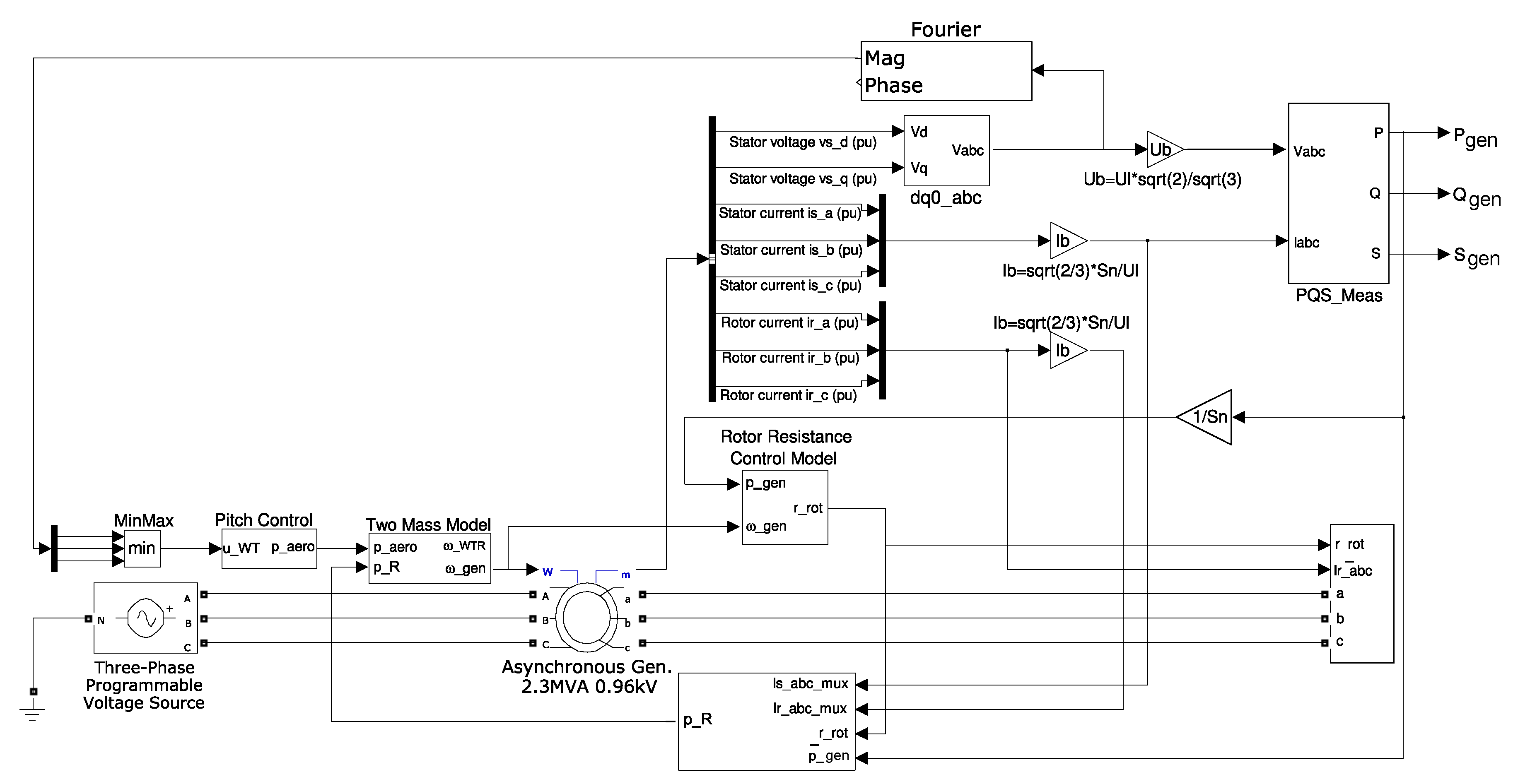
Type 2 WTs are similar to Type 1B WTs. The main difference is in the control model and the generator system, as Type 2 WTs include a wound rotor asynchronous generator with the VRR. As a result, only these two models are presented. The mechanical model, and electrical measurements model are the same as those presented for Type 1A WTs (Section 3.1.2 and Section 3.1.4), and the UVRT pitch control model is the same as for Type 1B WTs (Section 3.2). Figure 12 shows the complete Type 2 WT model. Parameters of Type 2 WT are presented in Appendix B, Table A2.

3.3.1. Variable Rotor Resistance Control Model

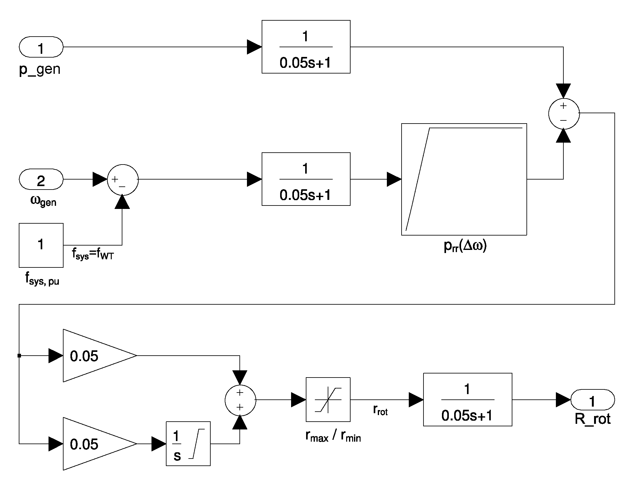
The VRR control model is shown in Figure 13. It modifies the rotor resistance value depending on P g e n and ω g e n , in order to slightly increase/decrease the slip of the generator. The generator speed ω g e n is compared to system frequency f to obtain its deviation Δ ω , which passes through a look-up table to obtain rotor resistance power P r r . At high wind speeds, P r r attempts to maximise the active power provided to the grid, as VSWTs [66]. This P r r is compared to P g e n . A PI controller is then used to estimate the rotor resistance R r o t value, attempting to minimise the error between P g e n (the measured variable) and P r r (the desired reference value).

3.3.2. Active Generated Power and Generator Set Model

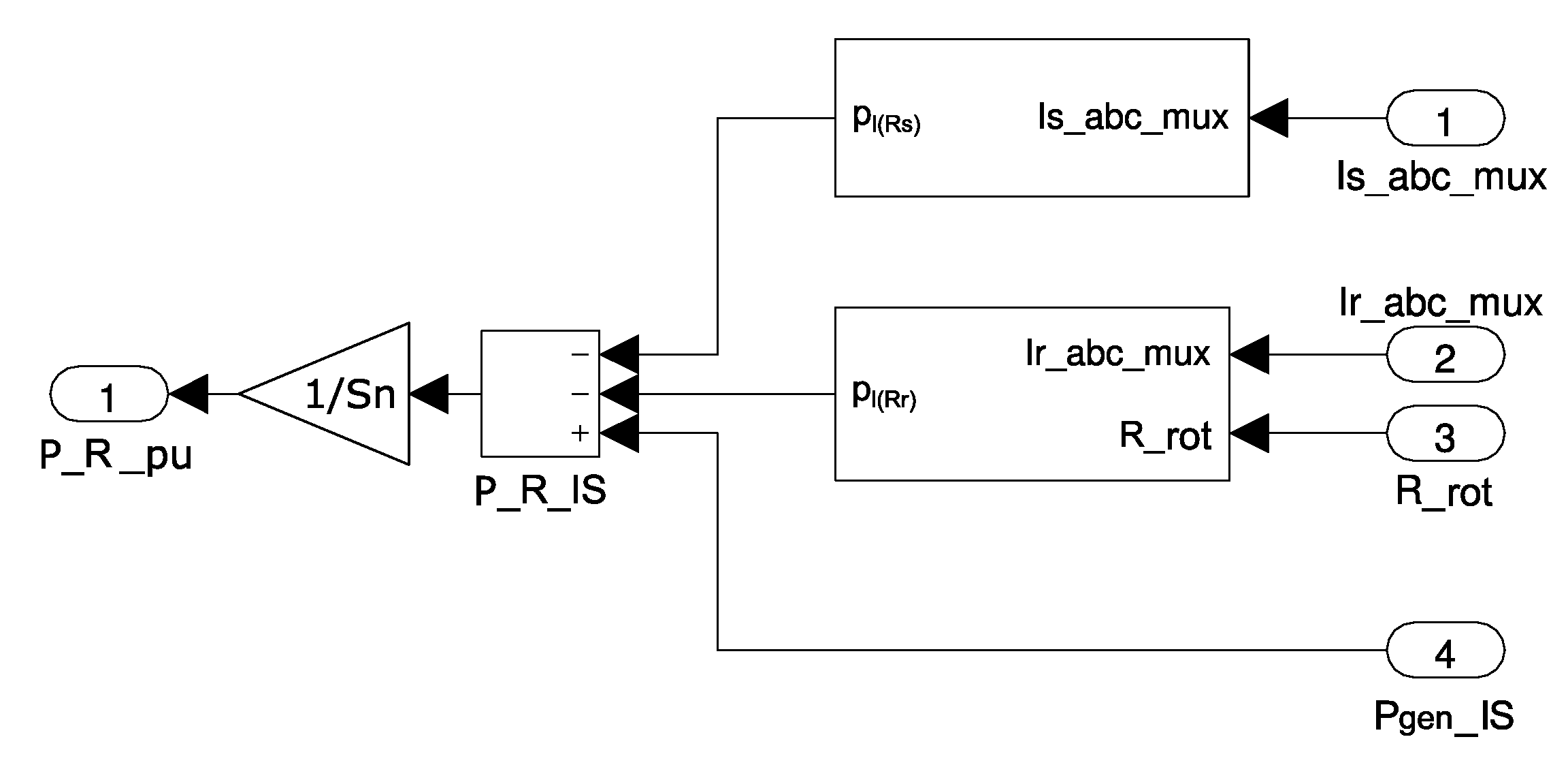
The active power is similar to that of Type 1 WTs (refer to Figure 6). However, in this case, the power losses due to the VRR should be considered when estimating the P l ( R r ) , as depicted in Figure 14. Indeed, above rated speed, the VRR control effectively allows the air-gap torque to be controlled, and varies the slip. This extra power generated is subsequently lost as heat by the additional VRR [67].
The wound rotor option of the Asynchronous Machine pu Units of SymPowerSystems is used. The three inputs for the voltage rotor are then calculated with a controlled voltage source (see Figure 15), which will be modified depending on the value of the rotor current I r and the rotor resistance value R r o t (determined with Figure 13).

4. Results

A three-phase voltage dip was simulated to test and compare the behaviour of Types 1 and 2 WTs facing UVRT. The generator active and reactive powers, and generator and rotor speeds of Types 1A, 1B and 2 WTs under such voltage dip were analysed. These simulations were carried out under a HIL real-time simulator environment with Matlab/Simulink.

4.1. Real-Time Simulation (Hardware-in-the-Loop)

Over the last decade, HIL experiments have generated great interest in the field of components and power system testing [68]. In fact, the association of HIL configurations plus a real-time simulator allows us to verify the design integrity and safely evaluate the performance of physical controller platforms [69]. In consequence, the general models of Types 1 and 2 WTs were simulated with MATLAB/Simulink combined with a real-time HIL. It must be highlighted that only one specific block of the library of the HIL real time simulator was used. This specific block is the ‘OPComms’, which is a requirement of the HIL. The rest of the model was completely based on standard Simulink blocks. The HIL model OP5600 from OPAL-RT shown in Figure 16 was used. It has one (out of four) Intel processor cores 3.2 GHz activated, a Xilintex Kintex 7 FPGA, and the Linux Redhat as the real-time operating system. It also includes 16 user input/outputs allowing for the exchange of information from/to another systems.

4.2. Simulation Results

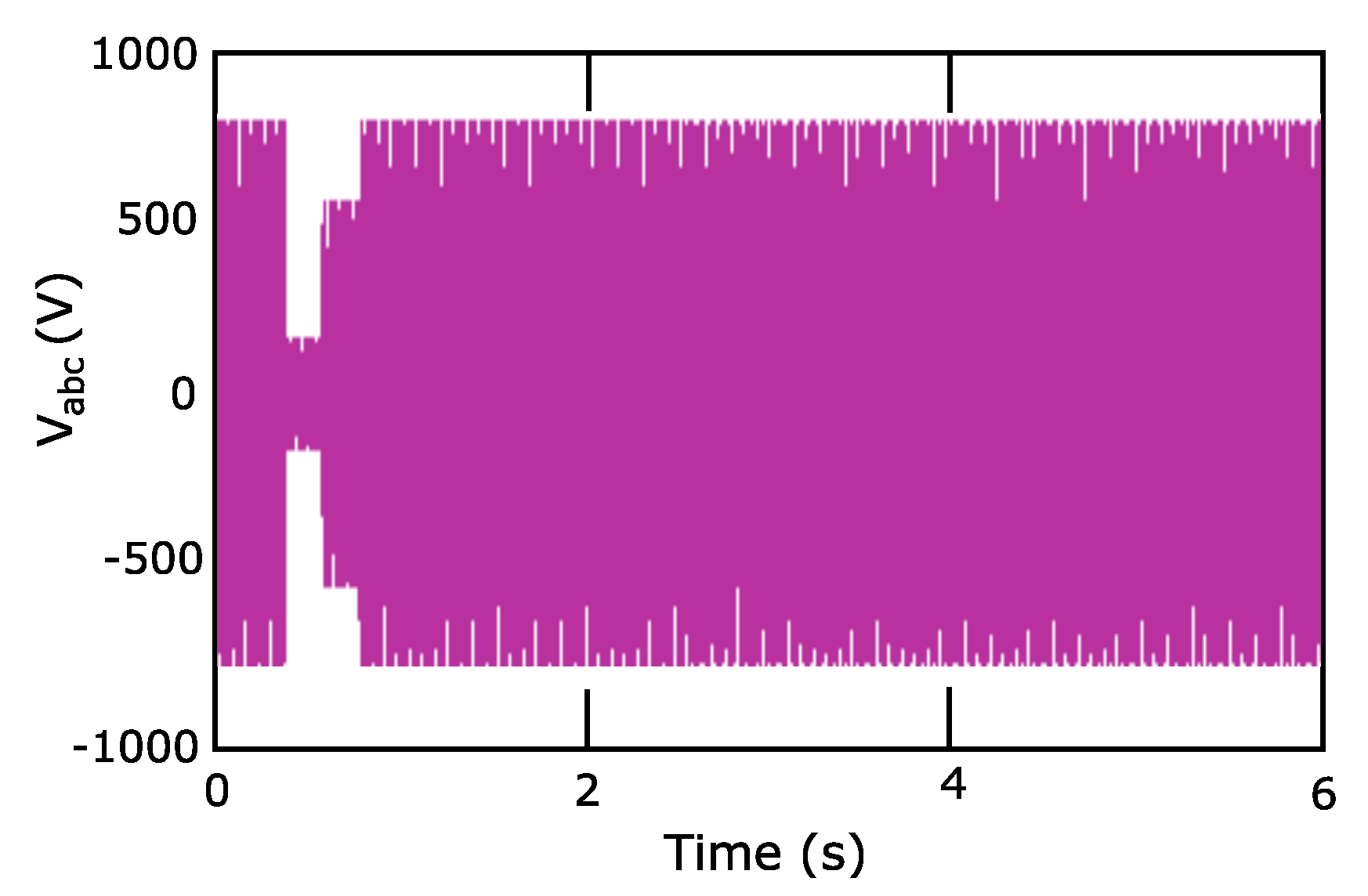
The three Types of wind turbines presented and described in this paper have faced the same three-phase voltage dip to test their electrical behaviour facing this kind of electrical fault. The voltage dip under consideration is shown in Figure 17.
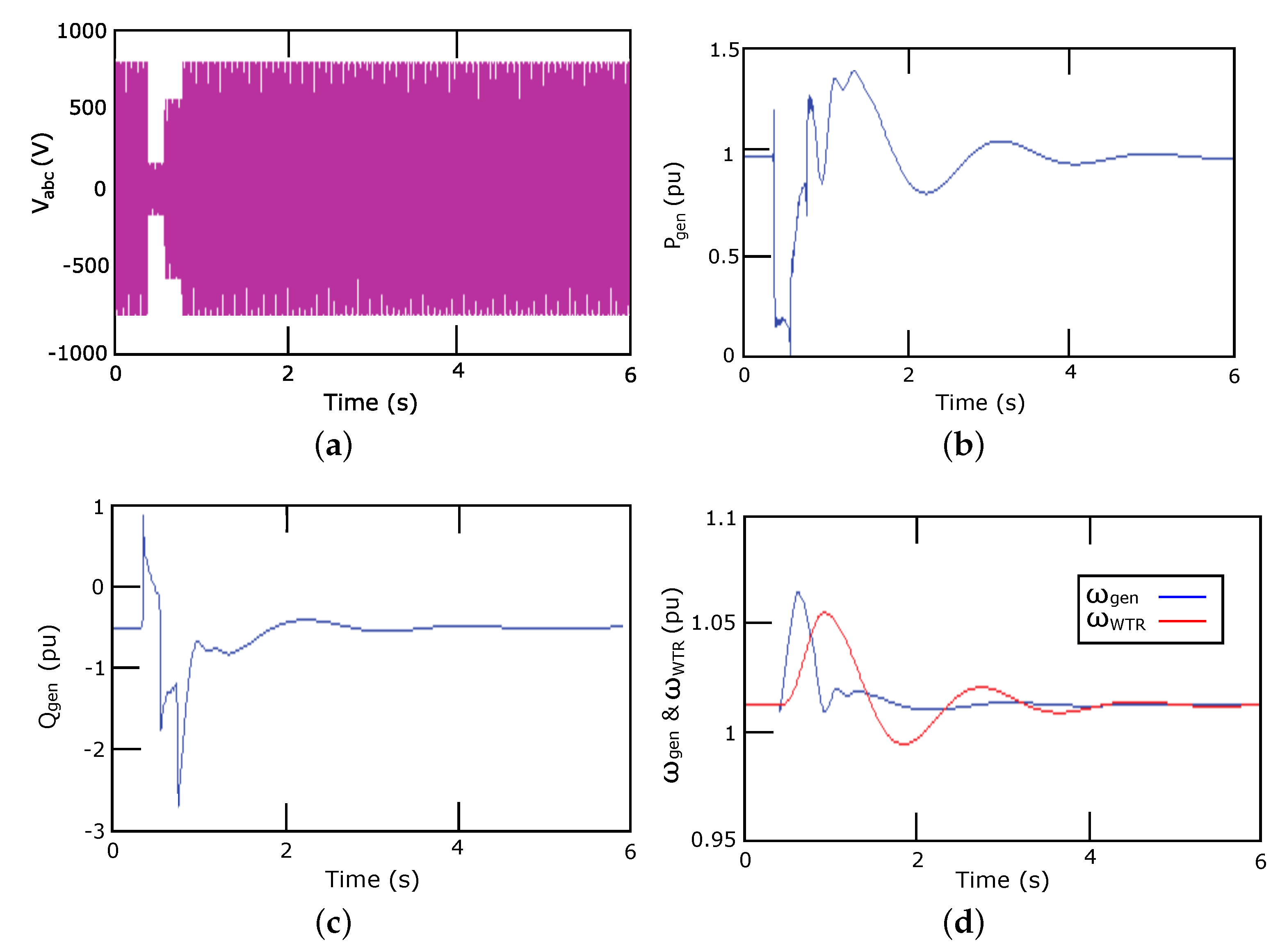
As seen in Figure 18, the active power P g e n of the Type 1A WT is nearly 1 pu before the voltage dip occurs. When the voltage drops, active power also reduces, even reaching 0 pu due to the low value of the voltage (please, refer to Figure 8). As voltage recovers, P g e n increases again, with a maximum value of 1.4 pu, and oscillates around 2 s. Then, it returns to its initial pre-fault value. With regard to reactive power Q g e n , its initial value is −0.5 pu. It suddenly increases, reaching 1 pu when the voltage is reduced to its minimum value. When the voltage increases, the reactive power reduces again. In fact, the minimum value of Q g e n is −2.5 pu. When the voltage dip is at its initial value, the reactive power takes around 2 s to stabilise. The rotational speeds of both generator and rotor increases when active power P g e n decreases. Due to the different inertia values of the generator and rotor (see Appendix A), the generator rotational speed acceleration/deceleration is faster and fluctuates more than the rotor speed.
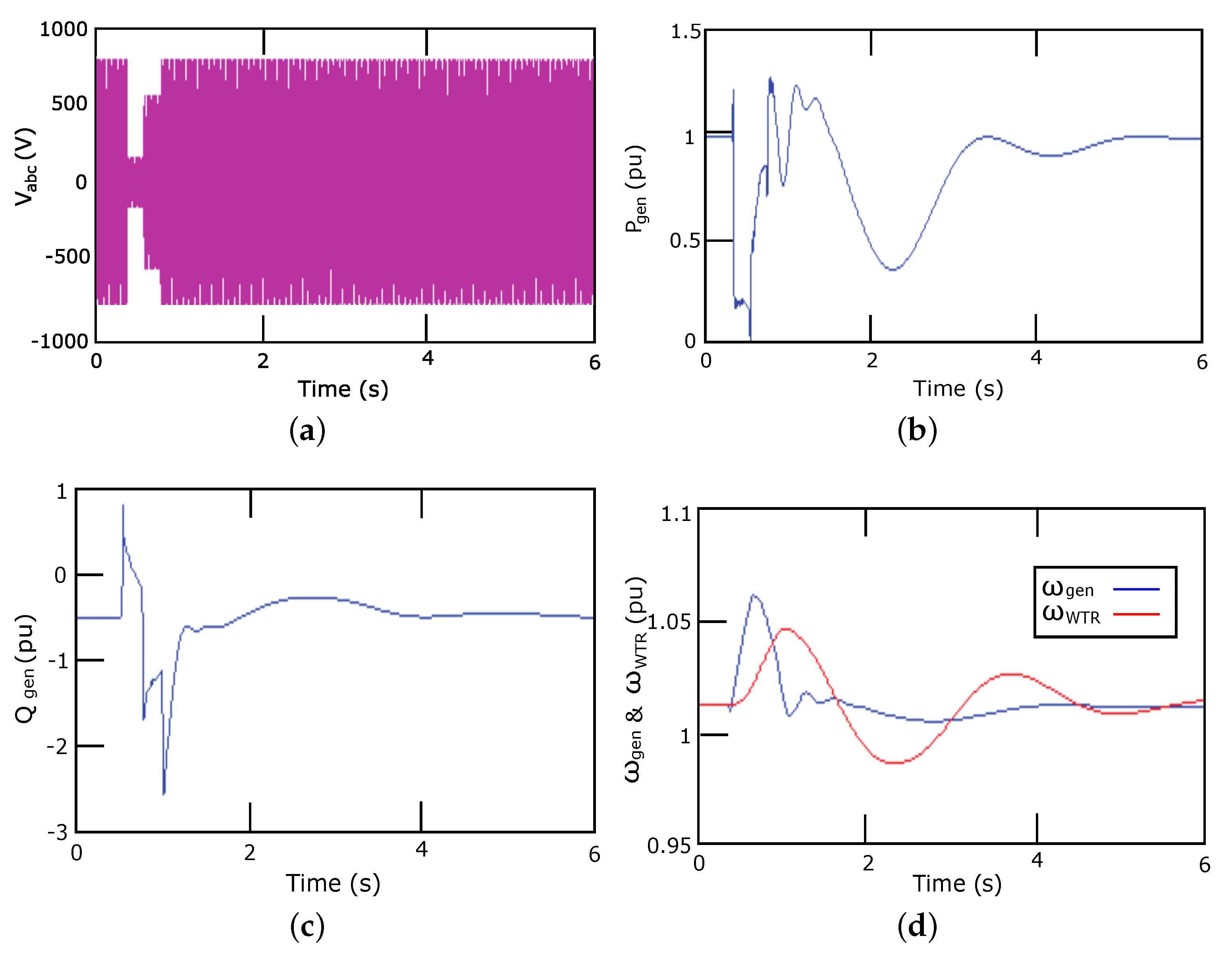
Similar results are shown in Figure 19 for the Type 1B WT. However, in this case, as voltage recovers after the dip, the maximum value of P g e n is 1.2 pu. This slight reduction compared to Type 1A is due to the UVRT pitch control of the Type 1B WT (refer to Section 3.2), which modifies the mechanical power of the WT. Reactive power and both rotational speeds have the same behaviour as those explained for the Type 1A WT in Figure 18, as no changes in those subsystems are carried out on Type 1B WT.
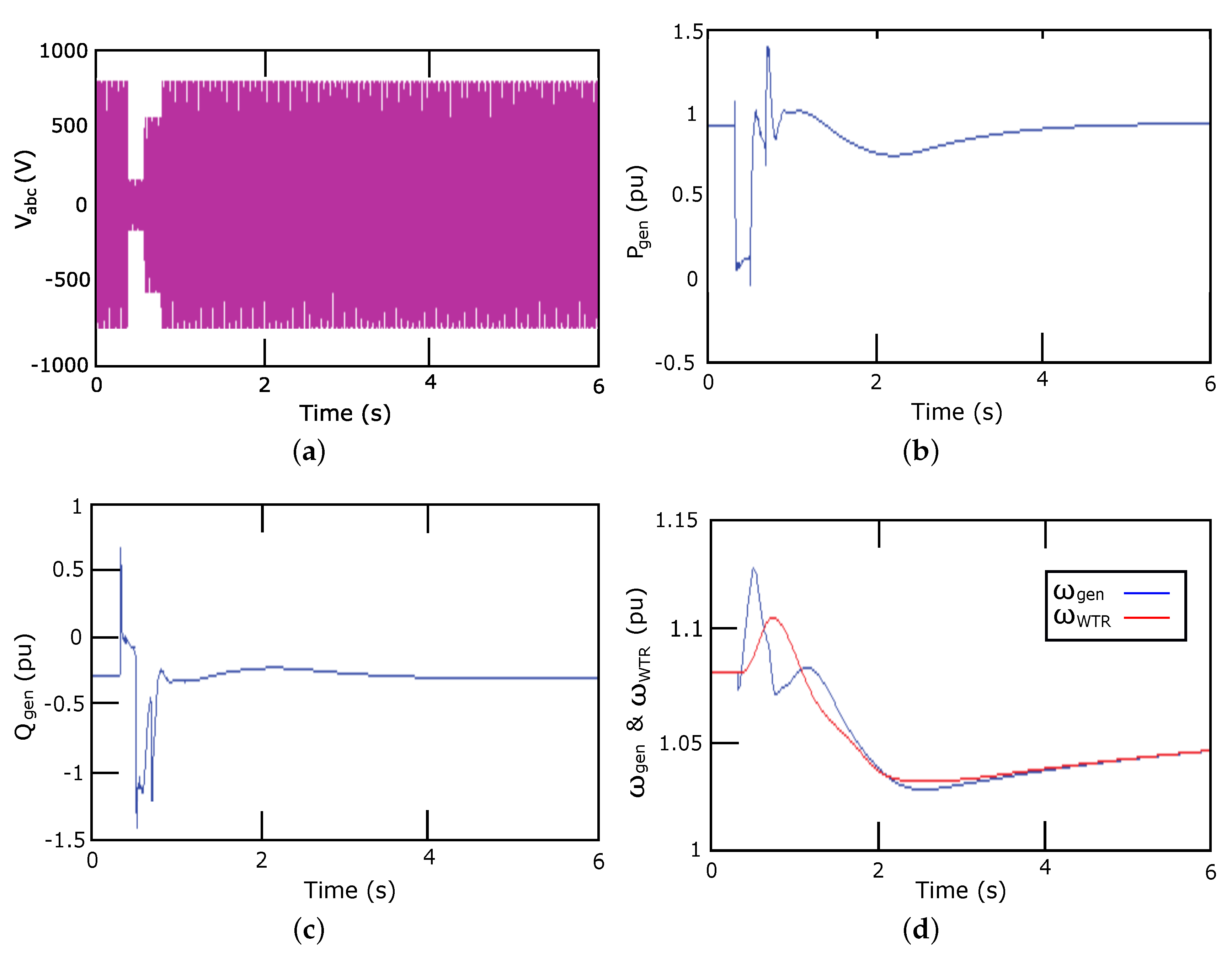
Figure 20 depicts active and reactive power of the Type 2 WT, as well as the rotational speeds. When the voltage drops, active power also reduces. As voltage recovers, P g e n increases again, with a maximum value of 1.4 pu, taking around 2 s to go back to its initial pre-fault value. Reactive power Q g e n suddenly increases as voltage is reduced. However, in this type of WT, the maximum value is reduced to 0.6 pu (instead of 1 pu for Type 1A and 1B WTs). In addition, the minimum value of Q g e n is higher than for Type 1A and 1B WTs (−1.5 pu instead of −2.5 pu). Moreover, when the voltage returns to its initial value, neither active nor reactive power have severe oscillations to recover. The rotational speeds of both generator and rotor increase when the active power P g e n decreases. In this case, as P g e n is less oscillatory than for the Type 1 WT, ω g e n and ω W T R also fluctuates less than in Type 1 WT.

5. Conclusions

In this paper, we conduct the modelling of Types 1 and 2 wind turbines with a hardware-in-the-loop combined with a real-time simulator, following Standard IEC 61400-27-1. The different subsystems required according to such Standard are presented, described and detailed for electrical simulation purposes, explaining the differences between Types 1A, 1B and 2 wind turbines. The different values for the parameters of the subsystems are also included, in contrast to the Standard IEC 61400-27-1 where the values for the parameters are not provided. In this way, other authors and researchers can perform simulations in terms of electrical response of such wind turbines. The active and reactive powers, together with the rotor and generator rotational speeds are simulated under a three-phase voltage dip, which is the worst-case scenario. The results show that the both Types 1A and 1B wind turbines have the same reactive power and rotational speed, whereas the active power of Type 1B presents fewer oscillations than Type 1A. Type 2 wind turbines yield the best active and reactive power responses, as their stability time is substantially lower than for Types 1A and 1B wind turbines. This paper thus provides practical information for Types 1 and 2 wind turbine models based on IEC 61400-27-1 submitted to voltage dips.

Author Contributions

Conceptualization, E.G.-L. and I.M.-B.; methodology, I.M.-B.; software, T.G.-S.; validation, A.F.-G. and E.G.-L.; formal analysis, T.G.-S.; investigation, T.G.-S.; resources, E.G.-L.; data curation, I.M.-B.; writing—original draft preparation, T.G.-S. and I.M.-B.; writing—review and editing, A.F.-G. and E.G.-L.; visualization, T.G.-S.; supervision, A.F.-G.; project administration, E.G.-L.; funding acquisition, A.F.-G. and E.G.-L. All authors have read and agreed to the published version of the manuscript.

Funding

This work was partially supported by the Spanish Ministry of Economy and Competitiveness and the European Union -FEDER Funds, ENE2016-78214-C2-1-R-; and the Spanish Ministry of Education, Culture and Sports -ref. FPU16/04282-.

Acknowledgments

The authors wish to thank Ángel Molina-García for his help in developing the models.

Conflicts of Interest

The authors declare no conflict of interest.

Abbreviations

The following abbreviations are used in this manuscript:
ω g e n Generator rotational speed
ω W T R Wind turbine rotor rotational speed
fGrid frequency
I n Nominal current at wind turbine terminals
P n Nominal active power of WT
P a e r o Aerodynamic power
Z b a s e Impedance base value
R r o t Variable rotor resistance
U n Nominal phase-to-phase voltage at wind turbine terminals
H W T R Inertia constant of WT rotor
H g e n Inertia constant of generator
k d r t Drive train stiffness
c d r t Drive train damping
FSWTsFixed Speed Wind Turbines
HILHardware-In-the-Loop
IECInternational Electrotechnical Commission
FRTFault-Ride-Through
LVRTLow-Voltage Ride-Through
VRRVariable Rotor Resistance
VSWTsVariable Speed Wind Turbines
WTsWind Turbines

Appendix A. Type 1A WT Parameters

Table A1. Parameters of Type 1 WT model.
VariableValue
T i n i t 0.989
H W T R 4
H g e n 1
k d r t 53.16
c d r t 5
S n 2.3 × 10 6
U L 960
f50
R S 0.01
L S 0.1248
R r 0.01
L r 0.1248
L m 7.98611
Pole pairs2

Appendix B. Type 2 WT Parameters

Table A2. Parameters of Type 2 WT model.
VariableValue
H W T R 4.06
H g e n 0.9
k d r t 1.30
c d r t 2.30
S n 2.3 × 10 6
U L 960
f50
R S 0.01
L S 0.1248
R r 0.01
L r 0.1248
L m 7.98611
Pole pairs2

References

  1. Fernández-Guillamón, A.; Villena-Lapaz, J.; Vigueras-Rodríguez, A.; García-Sánchez, T.; Molina-García, Á. An adaptive frequency strategy for variable speed wind turbines: Tpplication to high wind integration into power systems. Energies 2018, 11, 1436. [Google Scholar] [CrossRef] [Green Version]
  2. Fernández-Guillamón, A.; Das, K.; Cutululis, N.A.; Molina-García, Á. Offshore wind power integration into future power systems: Overview and trends. J. Mar. Sci. Eng. 2019, 7, 399. [Google Scholar] [CrossRef] [Green Version]
  3. Fernández-Guillamón, A.; Molina-García, A.; Vigueras-Rodríguez, A.; Gómez-Lázaro, E. Frequency Response and Inertia Analysis in Power Systems with High Wind Energy Integration. In Proceedings of the 2019 International Conference on Clean Electrical Power (ICCEP), Otranto, Italy, 2–4 July 2019; pp. 388–393. [Google Scholar]
  4. Fernández-Guillamón, A.; Gómez-Lázaro, E.; Muljadi, E.; Molina-García, Á. Power systems with high renewable energy sources: A review of inertia and frequency control strategies over time. Renew. Sustain. Energy Rev. 2019, 115, 109369. [Google Scholar] [CrossRef] [Green Version]
  5. Cardozo, C.; Van Ackooij, W.; Capely, L. Cutting plane approaches for frequency constrained economic dispatch problems. Electr. Power Syst. Res. 2018, 156, 54–63. [Google Scholar] [CrossRef]
  6. Fernández-Guillamón, A.; Martínez-Lucas, G.; Molina-García, Á.; Sarasua, J.I. An Adaptive Control Scheme for Variable Speed Wind Turbines Providing Frequency Regulation in Isolated Power Systems with Thermal Generation. Energies 2020, 13, 3369. [Google Scholar] [CrossRef]
  7. Global Wind Report 2019. Available online: https://gwec.net/global-wind-report-2019/ (accessed on 15 June 2020).
  8. Muñoz-Benavente, I.; Hansen, A.D.; Gómez-Lázaro, E.; García-Sánchez, T.; Fernández-Guillamón, A.; Molina-García, Á. Impact of combined demand-response and wind power plant participation in frequency control for multi-area power systems. Energies 2019, 12, 1687. [Google Scholar] [CrossRef] [Green Version]
  9. Villena-Ruiz, R.; Lorenzo-Bonache, A.; Honrubia-Escribano, A.; Jiménez-Buendía, F.; Gómez-Lázaro, E. Implementation of IEC 61400-27-1 Type 3 Model: Performance Analysis under Different Modeling Approaches. Energies 2019, 12, 2690. [Google Scholar] [CrossRef] [Green Version]
  10. Kumar, D.; Chatterjee, K. A review of conventional and advanced MPPT algorithms for wind energy systems. Renew. Sustain. Energy Rev. 2016, 55, 957–970. [Google Scholar] [CrossRef]
  11. Hansen, A.D.; Iov, F.; Blaabjerg, F.; Hansen, L.H. Review of contemporary wind turbine concepts and their market penetration. Wind. Eng. 2004, 28, 247–263. [Google Scholar] [CrossRef]
  12. Liang, X. Emerging power quality challenges due to integration of renewable energy sources. IEEE Trans. Ind. Appl. 2016, 53, 855–866. [Google Scholar] [CrossRef]
  13. Calif, R.; Schmitt, F.G. Multiscaling and joint multiscaling of the atmospheric wind speed and the aggregate power output from a wind farm. Nonlinear Process. 2014, 21, 379–392. [Google Scholar] [CrossRef] [Green Version]
  14. Calif, R.; Schmitt, F.G.; Huang, Y. Multifractal description of wind power fluctuations using arbitrary order Hilbert spectral analysis. Phys. A Stat. Mech. Appl. 2013, 392, 4106–4120. [Google Scholar] [CrossRef]
  15. Fernández-Guillamón, A.; Vigueras-Rodríguez, A.; Molina-García, Á. Analysis of power system inertia estimation in high wind power plant integration scenarios. IET Renew. Power Gener. 2019, 13, 2807–2816. [Google Scholar] [CrossRef]
  16. Heredia, F.J.; Cuadrado, M.D.; Corchero, C. On optimal participation in the electricity markets of wind power plants with battery energy storage systems. Comput. Oper. Res. 2018, 96, 316–329. [Google Scholar] [CrossRef] [Green Version]
  17. Zhang, W.; Fang, K. Controlling active power of wind farms to participate in load frequency control of power systems. IET Gener. Transm. Distrib. 2017, 11, 2194–2203. [Google Scholar] [CrossRef]
  18. Margaris, I.; Hansen, A.D.; Bech, J.; Andresen, B.; Sørensen, P.E. Implementation of IEC standard models for power system stability studies. In Proceedings of the 11th International Workshop on Large-scale Integration of Wind Power into Power Systems as Well as on Transmission Networks for Offshore Wind Power Plants, Lisbon, Portugal, 13–15 November 2012. [Google Scholar]
  19. Honrubia-Escribano, A.; Gomez-Lazaro, E.; Fortmann, J.; Sørensen, P.; Martin-Martinez, S. Generic dynamic wind turbine models for power system stability analysis: A comprehensive review. Renew. Sustain. Energy Rev. 2018, 81, 1939–1952. [Google Scholar] [CrossRef]
  20. Sørensen, P.; Andresen, B.; Fortmann, J.; Pourbeik, P. Modular structure of wind turbine models in IEC 61400-27-1. In Proceedings of the 2013 IEEE Power & Energy Society General Meeting, Vancouver, BC, Canada, 21–25 July 2013; pp. 1–5. [Google Scholar]
  21. Lorenzo-Bonache, A.; Villena-Ruiz, R.; Honrubia-Escribano, A.; Molina-García, A.; Gómez-Lázaro, E. Comparison of a standard type 3B WT model with a commercial build-in model. In Proceedings of the 2017 IEEE International Electric Machines and Drives Conference (IEMDC), Miami, FL, USA, 21–24 May 2017; pp. 1–6. [Google Scholar]
  22. Moschitta, A.; Carbone, P.; Muscas, C. Generalized likelihood ratio test for voltage dip detection. IEEE Trans. Instrum. Meas. 2011, 60, 1644–1653. [Google Scholar] [CrossRef]
  23. Moschitta, A.; Carbone, P.; Muscas, C. Performance comparison of advanced techniques for voltage dip detection. IEEE Trans. Instrum. Meas. 2012, 61, 1494–1502. [Google Scholar] [CrossRef]
  24. Gallo, D.; Landi, C.; Luiso, M.; Fiorucci, E. Survey on voltage dip measurements in standard framework. IEEE Trans. Instrum. Meas. 2013, 63, 374–387. [Google Scholar] [CrossRef]
  25. Ipinnimo, O.; Chowdhury, S.; Chowdhury, S.; Mitra, J. A review of voltage dip mitigation techniques with distributed generation in electricity networks. Electr. Power Syst. Res. 2013, 103, 28–36. [Google Scholar] [CrossRef]
  26. Hossain, M.; Pota, H.; Ugrinovskii, V.; Ramos, R. Decentralized control to augment LVRT capability of wind generators with STATCOM/ESS. In Proceedings of the IEEE PES General Meeting, Providence, RI, USA, 25–29 July 2010; pp. 1–8. [Google Scholar]
  27. Hossain, M.J.; Pota, H.R.; Ugrinovskii, V.A.; Ramos, R.A. Simultaneous STATCOM and pitch angle control for improved LVRT capability of fixed-speed wind turbines. IEEE Trans. Sustain. Energy 2010, 1, 142–151. [Google Scholar] [CrossRef] [Green Version]
  28. Hossain, M.J.; Pota, H.; Ramos, R. Robust STATCOM control for the stabilisation of fixed-speed wind turbines during low voltages. Renew. Energy 2011, 36, 2897–2905. [Google Scholar] [CrossRef] [Green Version]
  29. Noureldeen, O. Low voltage ride through strategies for SCIG wind turbines interconnected grid. Int. J. Electr. Comput. Sci. IJECS-IJENS 2011, 11, 6565–117502. [Google Scholar]
  30. Hossain, M.J.; Pota, H.R.; Ramos, R.A. Improved low-voltage-ride-through capability of fixed-speed wind turbines using decentralised control of STATCOM with energy storage system. IET Gener. Transm. Distrib. 2012, 6, 719–730. [Google Scholar] [CrossRef] [Green Version]
  31. Ren, J.; Hu, Y.; Ji, Y.; Liu, C. Low voltage ride-through control for fixed speed wind generators under grid unbalanced fault. In Proceedings of the 2012 Twenty-Seventh Annual IEEE Applied Power Electronics Conference and Exposition (APEC), Orlando, FL, USA, 5–9 February 2012; pp. 686–689. [Google Scholar]
  32. Wessels, C.; Hoffmann, N.; Molinas, M.; Fuchs, F.W. StatCom control at wind farms with fixed-speed induction generators under asymmetrical grid faults. IEEE Trans. Ind. Electron. 2012, 60, 2864–2873. [Google Scholar] [CrossRef]
  33. Moghadasi, A.; Islam, A. Enhancing LVRT capability of FSIG wind turbine using current source UPQC based on resistive SFCL. In Proceedings of the 2014 IEEE PES T&D Conference and Exposition, Chicago, IL, USA, 14–17 April 2014; pp. 1–5. [Google Scholar]
  34. Obando-Montaño, A.F.; Carrillo, C.; Cidrás, J.; Díaz-Dorado, E. A STATCOM with supercapacitors for low-voltage ride-through in fixed-speed wind turbines. Energies 2014, 7, 5922–5952. [Google Scholar] [CrossRef] [Green Version]
  35. Moghadasi, A.; Sarwat, A.; Guerrero, J.M. A comprehensive review of low-voltage-ride-through methods for fixed-speed wind power generators. Renew. Sustain. Energy Rev. 2016, 55, 823–839. [Google Scholar] [CrossRef] [Green Version]
  36. Heydari-Doostabad, H.; Khalghani, M.R.; Khooban, M.H. A novel control system design to improve LVRT capability of fixed speed wind turbines using STATCOM in presence of voltage fault. Int. J. Electr. Power Energy Syst. 2016, 77, 280–286. [Google Scholar] [CrossRef]
  37. Fortmann, J.; Engelhardt, S.; Kretschmann, J.; Feltes, C.; Erlich, I. New generic model of DFG-based wind turbines for RMS-type simulation. IEEE Trans. Energy Convers. 2013, 29, 110–118. [Google Scholar] [CrossRef]
  38. Subramanian, C.; Casadei, D.; Tani, A.; Sørensen, P.; Blaabjerg, F.; McKeever, P. Implementation of electrical simulation model for IEC standard Type-3A generator. In Proceedings of the 2013 European Modelling Symposium, Manchester, UK, 20–22 November 2013; pp. 426–431. [Google Scholar]
  39. Altin, M.; Göksu, Ö.; Hansen, A.D.; Sørensen, P.E. Aggregated wind power plant models consisting of IEC wind turbine models. In Proceedings of the 2015 IEEE Eindhoven PowerTech, Eindhoven, The Netherlands, 29 June–2 July 2015; pp. 1–5. [Google Scholar]
  40. Göksu, Ö.; Altin, M.; Fortmann, J.; Sørensen, P.E. Field validation of IEC 61400-27-1 wind generation type 3 model with plant power factor controller. IEEE Trans. Energy Convers. 2016, 31, 1170–1178. [Google Scholar] [CrossRef] [Green Version]
  41. Honrubia-Escribano, A.; Jiménez-Buendía, F.; Gómez-Lázaro, E.; Fortmann, J. Validation of generic models for variable speed operation wind turbines following the recent guidelines issued by IEC 61400-27. Energies 2016, 9, 1048. [Google Scholar] [CrossRef] [Green Version]
  42. Honrubia-Escribano, A.; Jimenez-Buendia, F.; Gomez-Lazaro, E.; Fortmann, J. Field validation of a standard type 3 wind turbine model for power system stability, according to the requirements imposed by IEC 61400-27-1. IEEE Trans. Energy Convers. 2017, 33, 137–145. [Google Scholar] [CrossRef]
  43. Lorenzo-Bonache, A.; Honrubia-Escribano, A.; Jiménez-Buendía, F.; Molina-García, Á.; Gómez-Lázaro, E. Generic type 3 wind turbine model based on IEC 61400-27-1: Parameter analysis and transient response under voltage dips. Energies 2017, 10, 1441. [Google Scholar] [CrossRef] [Green Version]
  44. Honrubia-Escribano, A.; Jiménez-Buendía, F.; Sosa-Avendaño, J.L.; Gartmann, P.; Frahm, S.; Fortmann, J.; Sørensen, P.E.; Gómez-Lázaro, E. Fault-ride trough validation of IEC 61400-27-1 type 3 and type 4 models of different wind turbine manufacturers. Energies 2019, 12, 3039. [Google Scholar] [CrossRef] [Green Version]
  45. Wang, L.; Zhang, Z.; Long, H.; Xu, J.; Liu, R. Wind turbine gearbox failure identification with deep neural networks. IEEE Trans. Ind. Inform. 2016, 13, 1360–1368. [Google Scholar] [CrossRef]
  46. Hansen, A.D.; Hansen, L.H. Wind turbine concept market penetration over 10 years (1995–2004). Wind Energy An Int. J. Prog. Appl. Wind Power Convers. Technol. 2007, 10, 81–97. [Google Scholar] [CrossRef]
  47. Thet, A.K.; Saitoh, H. Pitch control for improving the low-voltage ride-through of wind farm. In Proceedings of the 2009 Transmission & Distribution Conference & Exposition: Asia and Pacific, Seoul, Korea, 26–30 October 2009; pp. 1–4. [Google Scholar]
  48. Commission, I.E. Wind Turbines—Part 21: Measurement and Assessment of Power Quality Characteristics of Grid Connected Wind Turbines; IEC 61400-21; International Electrotechnical Commission (IEC): Geneva, Switzerland, 2008. [Google Scholar]
  49. IEC 61400-27-1. Electrical Simulation Models—Wind Turbines; Technical Report. 2015. Available online: https://webstore.iec.ch/publication/21811 (accessed on 6 August 2012).
  50. Vázquez-Hernández, C.; Serrano-González, J.; Centeno, G. A Market-Based Analysis on the Main Characteristics of Gearboxes Used in Onshore Wind Turbines. Energies 2017, 10, 1686. [Google Scholar] [CrossRef] [Green Version]
  51. Polinder, H. Overview of and trends in wind turbine generator systems. In Proceedings of the 2011 IEEE Power and Energy Society General Meeting, Detroit, MI, USA, 24–28 July 2011; pp. 1–8. [Google Scholar]
  52. Zhao, H.; Wu, Q.; Sørensen, P.E.; Bech, J.; Andresen, B. Implementation of draft IEC generic model of Type 1 wind turbine generator in PowerFactory and Simulink. In Proceedings of the 12th International Workshop on Large-scale Integration of Wind Power into Power Systems as Well as on Transmission Networks for Offshore Wind Power Plants, London, UK, 22–24 October 2013. [Google Scholar]
  53. Duong, M.Q.; Grimaccia, F.; Leva, S.; Mussetta, M.; Le, K.H. Improving transient stability in a grid-connected squirrel-cage induction generator wind turbine system using a fuzzy logic controller. Energies 2015, 8, 6328–6349. [Google Scholar] [CrossRef] [Green Version]
  54. De Prada, M.; Dominguez-Garcia, J.L.; Mancilla-David, F.; Muljadi, E.; Singh, M.; Gomis-Bellmunt, O.; Sumper, A. Type-2 wind turbine with additional sub-synchronous resonance damping. In Proceedings of the 2013 IEEE Green Technologies Conference (GreenTech), Denver, CO, USA, 4–5 April 2013; pp. 226–232. [Google Scholar]
  55. Cheng, M.; Zhu, Y. The state of the art of wind energy conversion systems and technologies: A review. Energy Convers. Manag. 2014, 88, 332–347. [Google Scholar] [CrossRef]
  56. Pérez, J.M.P.; Márquez, F.P.G.; Tobias, A.; Papaelias, M. Wind turbine reliability analysis. Renew. Sustain. Energy Rev. 2013, 23, 463–472. [Google Scholar] [CrossRef]
  57. Sumathi, S.; Ashok Kumar, L.; Surekha, P. Wind Energy Conversion Systems. In Solar PV and Wind Energy Conversion Systems: An Introduction to Theory, Modeling with MATLAB/SIMULINK, and the Role of Soft Computing Techniques; Springer International Publishing: Cham, Switzerland, 2015; pp. 247–307. [Google Scholar] [CrossRef]
  58. Fernández-Guillamón, A.; Sarasúa, J.I.; Chazarra, M.; Vigueras-Rodríguez, A.; Fernández-Muñoz, D.; Molina-García, Á. Frequency control analysis based on unit commitment schemes with high wind power integration: A Spanish isolated power system case study. Int. J. Electr. Power Energy Syst. 2020, 121, 106044. [Google Scholar] [CrossRef]
  59. Liu, J.; Gao, Y.; Geng, S.; Wu, L. Nonlinear control of variable speed wind turbines via fuzzy techniques. IEEE Access 2016, 5, 27–34. [Google Scholar] [CrossRef]
  60. Margaris, I.D.; Hansen, A.D.; Sørensen, P.; Hatziargyriou, N.D. Illustration of modern wind turbine ancillary services. Energies 2010, 3, 1290–1302. [Google Scholar] [CrossRef]
  61. Wan, S.; Cheng, K.; Sheng, X.; Wang, X. Characteristic analysis of DFIG wind turbine under blade mass imbalance fault in view of wind speed spatiotemporal distribution. Energies 2019, 12, 3178. [Google Scholar] [CrossRef] [Green Version]
  62. Boukhezzar, B.; Siguerdidjane, H. Nonlinear control of a variable-speed wind turbine using a two-mass model. IEEE Trans. Energy Convers. 2010, 26, 149–162. [Google Scholar] [CrossRef]
  63. Chu, J.; Yuan, L.; Hu, Y.; Pan, C.; Pan, L. Comparative analysis of identification methods for mechanical dynamics of large-scale wind turbine. Energies 2019, 12, 3429. [Google Scholar] [CrossRef] [Green Version]
  64. Villena-Ruiz, R.; Honrubia-Escribano, A.; Fortmann, J.; Gómez-Lázaro, E. Field validation of a standard Type 3 wind turbine model implemented in DIgSILENT-PowerFactory following IEC 61400-27-1 guidelines. Int. J. Electr. Power Energy Syst. 2020, 116, 105553. [Google Scholar] [CrossRef]
  65. Ekanayake, J.B.; Holdsworth, L.; Jenkins, N. Comparison of 5th order and 3rd order machine models for doubly fed induction generator (DFIG) wind turbines. Electr. Power Syst. Res. 2003, 67, 207–215. [Google Scholar] [CrossRef]
  66. Società Anonima Costruzioni Elettromeccaniche. Technical Application Papers No. 13, Wind Power Plants; ABB SACE: Via Baioni, Italy, 2015; Volume 35, p. 4123. [Google Scholar]
  67. Anaya-Lara, O.; Jenkins, N.; Ekanayake, J.B.; Cartwright, P.; Hughes, M. Wind Energy Generation: Modelling and Control; John Wiley & Sons: West Sussex, UK, 2011. [Google Scholar]
  68. Brandl, R. Operational range of several interface algorithms for different power hardware-in-the-loop setups. Energies 2017, 10, 1946. [Google Scholar] [CrossRef] [Green Version]
  69. Matar, M.; Karimi, H.; Etemadi, A.; Iravani, R. A high performance real-time simulator for controllers hardware-in-the-loop testing. Energies 2012, 5, 1713–1733. [Google Scholar] [CrossRef]
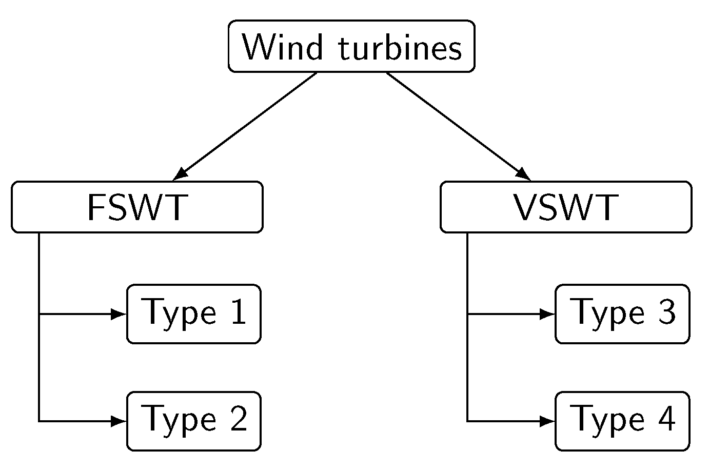
Figure 1. Classification of wind turbines.
Energies 13 04078 g001
Figure 2. Definition of voltage dip.
Energies 13 04078 g002
Figure 3. Main electrical and mechanical components of FSWTs. (a) Type 1 (b) Type 2.
Energies 13 04078 g003
Figure 4. Type 1A WT model.
Energies 13 04078 g004
Figure 5. Two-mass mechanical model.
Energies 13 04078 g005
Figure 6. Rotor and stator power losses model.
Energies 13 04078 g006
Figure 7. Conversion from dq to a, b, c system.
Energies 13 04078 g007
Figure 8. Model to calculate P, Q and S.
Energies 13 04078 g008
Figure 9. Type 1B WT model.
Energies 13 04078 g009
Figure 10. Wind turbine pitch control power model.
Energies 13 04078 g010
Figure 11. Time the protection system will be activated depending on U U V R T .
Energies 13 04078 g011
Figure 12. Type 2 WT model.
Energies 13 04078 g012
Figure 13. Rotor resistance control model.
Energies 13 04078 g013
Figure 14. Rotor and stator power losses model.
Energies 13 04078 g014
Figure 15. Rotor voltage set for the wound rotor asynchronous generator.
Energies 13 04078 g015
Figure 16. Real time simulator OP5600.
Energies 13 04078 g016
Figure 17. Voltage dip applied to Type 1 and 2 WTs.
Energies 13 04078 g017
Figure 18. Response of Type 1A WT (a) Voltage dip (b) Generator active power (c) Generator reactive power (d) Generator and turbine rotational speeds.
Energies 13 04078 g018
Figure 19. Response of Type 1B WT (a) Voltage dip (b) Generator active power (c) Generator reactive power (d) Generator and turbine rotational speeds.
Energies 13 04078 g019
Figure 20. Response of Type 2 WT (a) Voltage dip (b) Generator active power (c) Generator reactive power (d) Generator and turbine rotational speeds.
Energies 13 04078 g020