
Dynamic Analysis for the Hydraulic Leg Power of a Powered Roof Support


Abstract
:1. Introduction
2. Materials and Methods
2.1. Calculation Model for Actual Conditions
- N(t)—the power of the rock mass;
- f(t)—the time course of the dynamic force acting on the support;
- V(t)—the dynamic process of clamping the workings;
- *—the intertwining of two time functions.
- Nmax stoj—the maximum leg power, N·m·s−1;
- Dmax gór—the maximum power that the rock mass will exert on the support, N·m·s−1.
- Fgmax—the maximum value of dynamic force applied to a single leg, N;
- Vgmax—the maximum clamping speed of the excavation, m·s−1.
- Qzaw—the volume flow of the safety valve for a given pressure, m3·s−1;
- Pmax—the maximum working pressure of the leg matching the adopted allowable load-bearing capacity of the leg, N;
- kp—the leg’s overload coefficient.
2.2. Calculation Model for Test Conditions
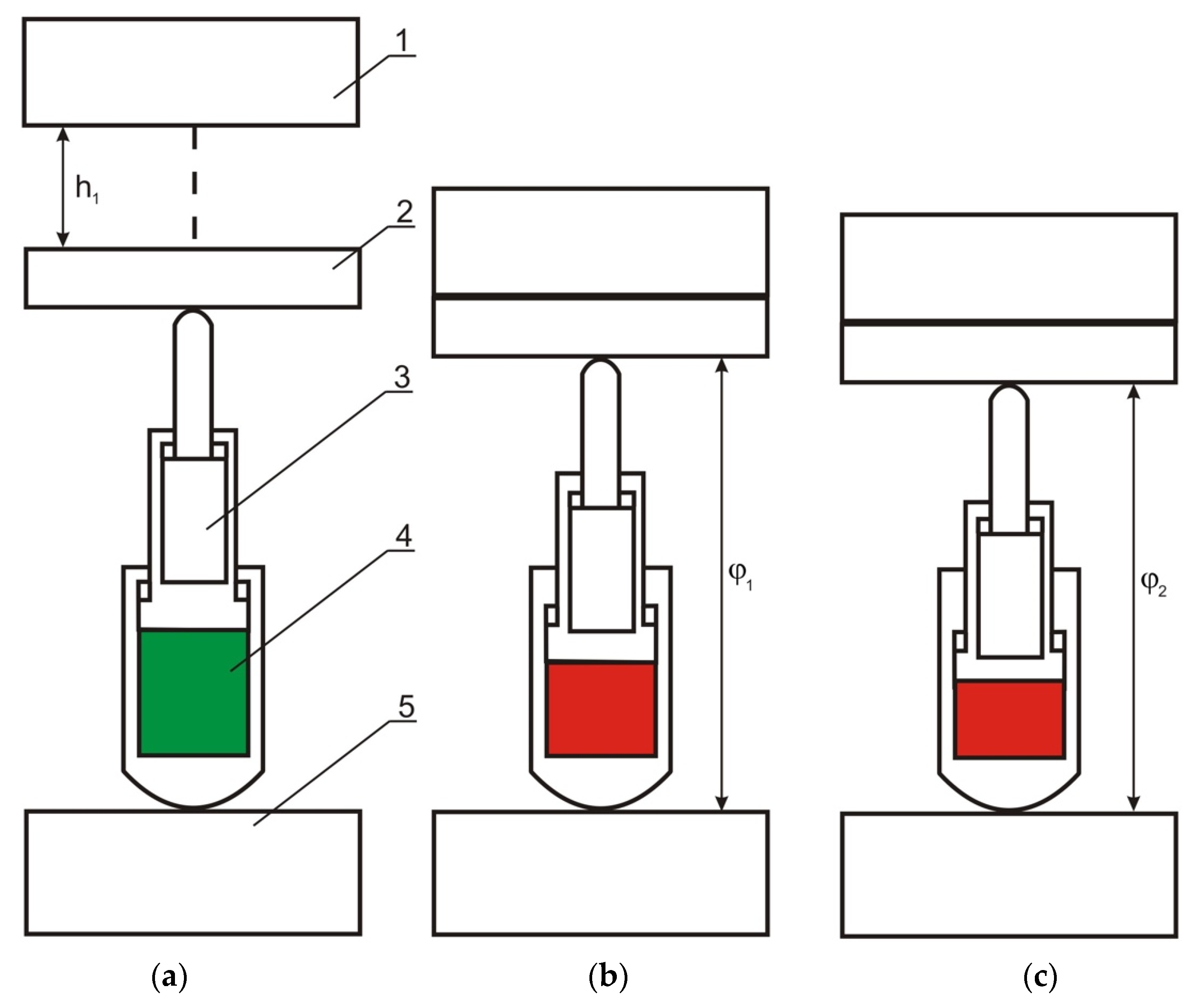
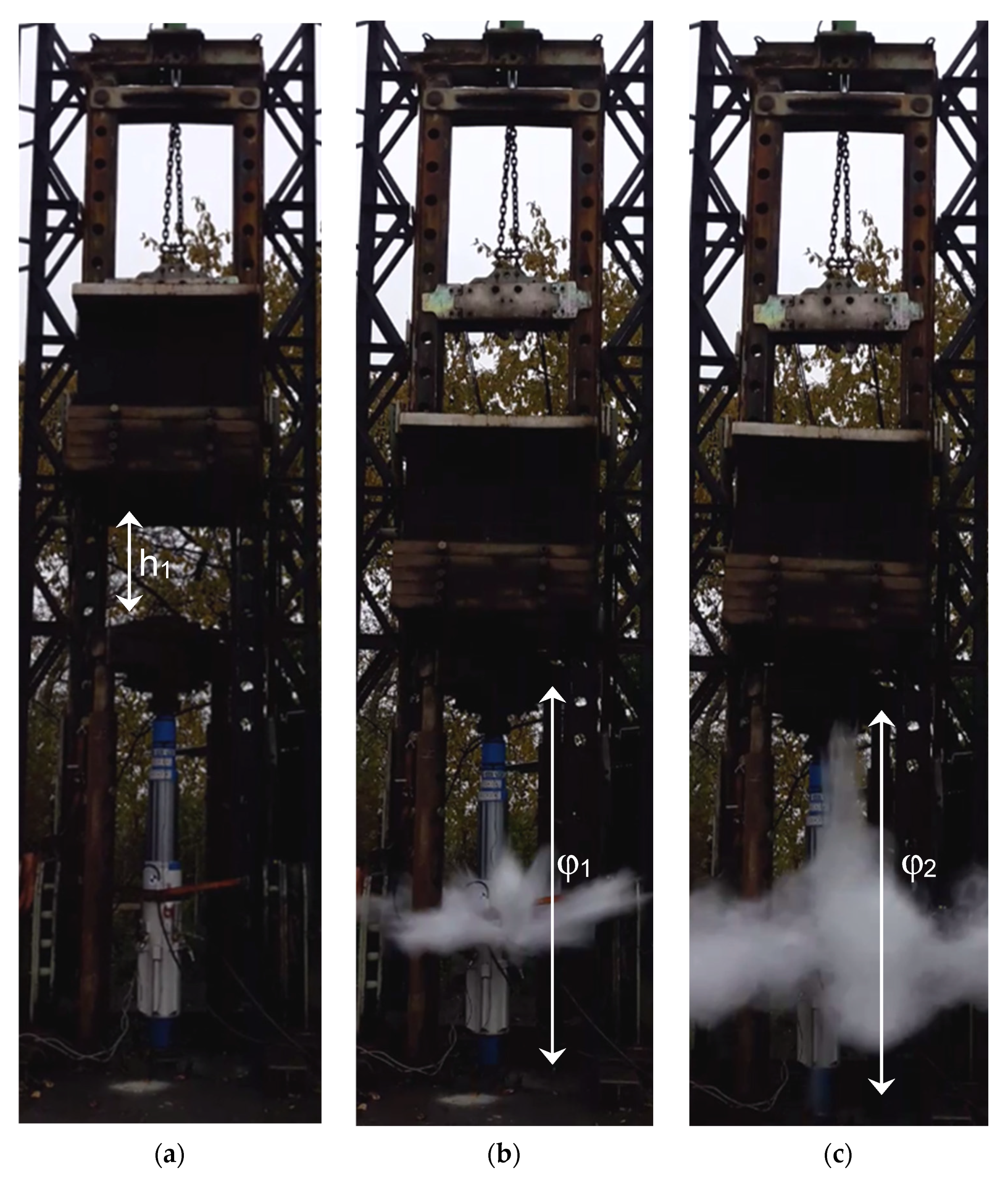
- φ—the total work of the leg slide in the moment of dynamic loading;
- P—the nominal pressure;
- d—the internal diameter of the hydraulic leg cylinder;
- hc—the total leg slide in the moment of dynamic loading.
- ε—the dynamic power occurring in the piston sub-space of the leg;
- E—the value of kinetic energy converted by the leg;
- φ—the total work of the leg slide in the moment of dynamic loading;
- hc—the total leg slide in the moment of dynamic loading;
- t—the time taken for the total leg slide of hc;
- δ—the hydraulic force acting on the piston of the leg at the moment of its retraction.
3. Conducted Tests
3.1. Test Bench Model
3.2. Bench Tests
4. Results and Discussion
5. Conclusions
Funding
Institutional Review Board Statement
Informed Consent Statement
Data Availability Statement
Conflicts of Interest
References
- Szurgacz, D.; Zhironkin, S.; Cehlár, M.; Vöth, S.; Spearing, S.; Liqiang, M. A Step-by-Step Procedure for Tests and Assessment of the Automatic Operation of a Powered Roof Support. Energies 2021, 14, 697. [Google Scholar] [CrossRef]
- Bortnowski, P.; Gładysiewicz, L.; Król, R.; Ozdoba, M. Energy Efficiency Analysis of Copper Ore Ball Mill Drive Systems. Energies 2021, 14, 1786. [Google Scholar] [CrossRef]
- Bajda, M.; Hardygóra, M. Analysis of Reasons for Reduced Strength of Multiply Conveyor Belt Splices. Energies 2021, 14, 1512. [Google Scholar] [CrossRef]
- Wodecki, J.; Góralczyk, M.; Krot, P.; Ziętek, B.; Szrek, J.; Worsa-Kozak, M.; Zimroz, R.; Śliwiński, P.; Czajkowski, A. Process Monitoring in Heavy Duty Drilling Rigs—Data Acquisition System and Cycle Identification Algorithms. Energies 2020, 13, 6748. [Google Scholar] [CrossRef]
- Ziętek, B.; Banasiewicz, A.; Zimroz, R.; Szrek, J.; Gola, S. A Portable Environmental Data-Monitoring System for Air Hazard Evaluation in Deep Underground Mines. Energies 2020, 13, 6331. [Google Scholar] [CrossRef]
- Borkowski, P.J. Comminution of Copper Ores with the Use of a High-Pressure Water Jet. Energies 2020, 13, 6274. [Google Scholar] [CrossRef]
- Tutak, M.; Brodny, J.; Szurgacz, D.; Sobik, L.; Zhironkin, S. The Impact of the Ventilation System on the Methane Release Hazard and Spontaneous Combustion of Coal in the Area of Exploitation—A Case Study. Energies 2020, 13, 4891. [Google Scholar] [CrossRef]
- Góralczyk, M.; Krot, P.; Zimroz, R.; Ogonowski, S. Increasing Energy Efficiency and Productivity of the Comminution Process in Tumbling Mills by Indirect Measurements of Internal Dynamics—An Overview. Energies 2020, 13, 6735. [Google Scholar] [CrossRef]
- Sofranko, M.; Khouri, S.; Vegsoova, O.; Kacmary, P.; Mudarri, T.; Koncek, M.; Tyulenev, M.; Simkova, Z. Possibilities of Uranium Deposit Kuriskova Mining and Its Influence on the Energy Potential of Slovakia from Own Resources. Energies 2020, 13, 4209. [Google Scholar] [CrossRef]
- Sivák, P.; Tauš, P.; Rybár, R.; Beer, M.; Šimková, Z.; Baník, F.; Zhironkin, S.; Čitbajová, J. Analysis of the Combined Ice Storage (PCM) Heating System Installation with Special Kind of Solar Absorber in an Older House. Energies 2020, 13, 3878. [Google Scholar] [CrossRef]
- Zhironkin, S.; Selyukov, A.; Gasanov, M. Parameters of Transition from Deepening Longitudinal to Continuous Lateral Surface Mining Methods to Decrease Environmental Damage in Coal Clusters. Energies 2020, 13, 3305. [Google Scholar] [CrossRef]
- Beer, M.; Rybár, R.; Cehlár, M.; Zhironkin, S.; Sivák, P. Design and Numerical Study of the Novel Manifold Header for the Evacuated Tube Solar Collector. Energies 2020, 13, 2450. [Google Scholar] [CrossRef]
- Kawalec, W.; Suchorab, N.; Konieczna-Fuławka, M.; Król, R. Specific Energy Consumption of a Belt Conveyor System in a Continuous Surface Mine. Energies 2020, 13, 5214. [Google Scholar] [CrossRef]
- Szrek, J.; Wodecki, J.; Błażej, R.; Zimroz, R. An Inspection Robot for Belt Conveyor Maintenance in Underground Mine—Infrared Thermography for Overheated Idlers Detection. Appl. Sci. 2020, 10, 4984. [Google Scholar] [CrossRef]
- Kozłowski, T.; Wodecki, J.; Zimroz, R.; Błażej, R.; Hardygóra, M. A Diagnostics of Conveyor Belt Splices. Appl. Sci. 2020, 10, 6259. [Google Scholar] [CrossRef]
- Schmidt, S.; Zimroz, R.; Chaari, F.; Heyns, P.S.; Haddar, M. A Simple Condition Monitoring Method for Gearboxes Operating in Impulsive Environments. Sensors 2020, 20, 2115. [Google Scholar] [CrossRef] [Green Version]
- Hebda-Sobkowicz, J.; Zimroz, R.; Wyłomańska, A. Selection of the Informative Frequency Band in a Bearing Fault Diagnosis in the Presence of Non-Gaussian Noise—Comparison of Recently Developed Methods. Appl. Sci. 2020, 10, 2657. [Google Scholar] [CrossRef] [Green Version]
- Sobik, L.; Brodny, J.; Buyalich, G.; Strelnikov, P. Analysis of methane hazard in longwall working equipped with a powered longwall complex. E3S Web Conf. 2020, 174, 1011. [Google Scholar] [CrossRef]
- Brodny, J. Determining the working characteristic of a friction joint in a yielding support. Arch. Min. Sci. 2010, 55, 733–746. [Google Scholar]
- Brodny, J. Tests of Friction Joints in Mining Yielding Supports Under Dynamic Load. Arch. Min. Sci. 2011, 56, 303–318. [Google Scholar]
- Budirskỳ, S. Interaction of powered supports and the strata in coal seams under a heavy roof. Int. J. Min. Eng. 1985, 3, 113–138. [Google Scholar] [CrossRef]
- Szurgacz, D.; Brodny, J. Analysis of the Influence of Dynamic Load on the Work Parameters of a Powered Roof Support’s Hydraulic Leg. Sustainability 2019, 11, 2570. [Google Scholar] [CrossRef] [Green Version]
- Stoiński, K.; Mika, M. Dynamics of Hydraulic Leg of Powered Longwall Support. J. Min. Sci. 2003, 39, 72–77. [Google Scholar] [CrossRef]
- Szweda, S. Dynamic action of rock mass on the powered support legs. J. Min. Sci. 2003, 38, 154–161. [Google Scholar] [CrossRef]
- Gwiazda, J.B. Górnicza Obudowa Hydrauliczna Odporna na Tąpania; Wydawnictwo Śląsk: Katowice, Poland, 1997. [Google Scholar]
- Budirskỳ, S.; Martinec, P. Influence of support resistance on roof control in single-pass thick-seam mining (4.5 m): A case history. Min. Sci. Technol. 1986, 4, 59–67. [Google Scholar] [CrossRef]
- Klishin, V.I.; Klishin, S.V. Coal Extraction from Thick Flat and Steep Beds. J. Min. Sci. 2010, 46, 149–159. [Google Scholar] [CrossRef]
- Buyalich, G.; Buyalich, K.; Byakov, M. Factors Determining the Size of Sealing Clearance in Hydraulic Legs of Powered Supports. E3S Web Conf. 2017, 21, 3018. [Google Scholar] [CrossRef] [Green Version]
- Buyalich, G.; Byakov, M.; Buyalich, K. Factors Determining Operation of Lip Seal in the Sealed Gap of the Hydraulic Props of Powered Supports. E3S Web Conf. 2017, 41, 1045. [Google Scholar] [CrossRef]
- Buyalich, G.; Byakov, M.; Buyalich, K.; Shtenin, E. Development of Powered Support Hydraulic Legs with Improved Performance. E3S Web Conf. 2019, 105, 3025. [Google Scholar] [CrossRef]
- Kabiesz, J.; Konopko, W.; Patyńska, R. Annual Report on the State of Basic Natural and Technical Hazards in Hard Coal Mining; GIG: Katowice, Poland, 2020; pp. 97–101. [Google Scholar]
- Stoiński, K. Mining Roof Support in Hazardous Conditions of Mining Tremors; The Central Mining Institute: Katowice, Poland, 2000. [Google Scholar]
- Świątek, J.; Janoszek, T.; Cichy, T.; Stoiński, K. Computational Fluid Dynamics Simulations for Investigation of the Damage Causes in Safety Elements of Powered Roof Supports—A Case Study. Energies 2021, 14, 1027. [Google Scholar] [CrossRef]
- Tomski, L.; Kukla, S. Dynamical response of bar-fluid-shell system simulating hydraulic cylinder subjected to arbitrary axial excitation. J. Sound Vib. 1984, 92, 273–284. [Google Scholar] [CrossRef]
- Tomski, L.; Uzny, S. A hydraulic cylinder subjected to Euler’s load in aspect of the stability and free vibrations taking into account discrete elastic elements. Arch. Civ. Mech. Eng. 2011, 11, 769–785. [Google Scholar] [CrossRef]
- Sochacki, W.; Tomski, L. Free Vibration and Dynamic Stability of a Hydraulic Cylinder Set. Mach. Dyn. Probl. 1999, 23, 91–104. [Google Scholar]
- Tomski, L. Forced Vibrations of Hydraulic Props of Longwall Supports. Arch. Min. Sci. 1979, 24, 19–33. [Google Scholar]
- Tomski, L. Dynamika Stojaków Hydraulicznych Obudów Górniczych; Zeszyty Naukowe Politechniki Częstochowskiej, Nr 17; Politechnika Częstochowska: Czestochowa, Poland, 1979. [Google Scholar]
- Tomski, L. Elastic Carrying Capasity of a Hydraulic Prop. Eng. Trans. 1977, 25, 247–263. [Google Scholar]
- Tomski, L. Elastic Stability of Hydraulic Props of Longwall Supports. Arch. Min. Sci. 1978, 23, 217–231. [Google Scholar]
- Tomski, L. Longitudinal Mass Impact of Hydraulic Servo. Z. Angew. Math. Mech. 1981, 61, 191–193. [Google Scholar]
- Tomski, L.; Chwalba, W.; Kukla, S.; Mrowiec, A.; Posiadała, B. Dynamical Response of Hydraulic Cylinder Connected with External Shock Absorber Subjected to Axial Mass Impact. Arch. Min. Sci. 1987, 32, 439–454. [Google Scholar]
- Yang, Z.K.; Sun, Z.Y.; Jiang, S.B.; Mao, Q.H.; Liu, P.; Xu, C.Z. Structural Analysis on impact-mechanical properties of ultra-high hydraulic support. Int. J. Simul. Model 2020, 1, 17–28. [Google Scholar] [CrossRef]
- Uzny, S. Free Vibrations of an Elastically Supported Geometrically Nonlinear Column Subjected to a Generalized Load with a Force Directed toward the Positive Pole. J. Eng. Mech. 2011, 137, 740–748. [Google Scholar] [CrossRef]
- Uzny, S.; Osadnik, M. Influence of longitudinal elastic support on stability of a partially tensioned column. In Proceedings of the 23rd International Conference in Engineering Mechanics, Svratka, Czech Republic, 15–18 May 2017; pp. 1006–1009. [Google Scholar]
- Uzny, S.; Kutrowski, Ł. Strength analysis of a telescopic hydraulic cylinder elastically mounted on both ends. J. App. Math. Comput. Mech. 2019, 18, 89–96. [Google Scholar] [CrossRef]
- Uzny, S.; Kutrowski, Ł. The Effect of the Type of Mounting on Stability of a Hydraulic Telescopic Cylinder. Mach. Dyn. Res. 2018, 42, 53–60. [Google Scholar]
- Uzny, S. Free vibrations and stability of hydraulic cylinder fixed elastically on both ends. Proc. Appl. Math. Mech. 2009, 9, 303–304. [Google Scholar] [CrossRef]
- Kong, D.Z.; Jiang, W.; Chen, Y. Study of roof stability of the end of working face in upward longwall top coal. Arab. J. Geosci. 2017, 10, 185. [Google Scholar] [CrossRef]
- Michalak, M. Gradual-Randomized model of powered roof supports working cycle. Comput. Sci. Inform. Technol. 2015, 15–24. [Google Scholar] [CrossRef]
- Axin, M. Mobile Working Hydraulic System Dynamics. Ph.D. Thesis, Linköping Studies in Science and Technology, Linköping University, Linköping, Sweden, 2015. [Google Scholar]
- Brady, B.H.G.; Brown, E.T. Rock Mechanics for Underground Mining; Kluwer Academic Publishers: New York, NY, USA, 2005. [Google Scholar]
- Singh, R.; Singh, T.N. Investigation into the behavior of a support system and roof strata during sublevel caving of a thick coal seam. Geotech. Geol. Eng. 1999, 17, 21–35. [Google Scholar] [CrossRef]
- Gil, J.; Kołodziej, M.; Szurgacz, D.; Stoiński, K. Introduction of standardization of powered roof supports to increase production efficiency of Polska Grupa Górnicza, S.A. Min. Inform. Autom. Electr. Eng. 2019, 56, 33–38. [Google Scholar] [CrossRef]
- Szurgacz, K. An attempt to determine the dynamic powered of mechanized longwall housing leg deisgned to work in hazardous conditions of rock mass tremors—Discussion article. Res. Rep. Min. Environ. 2011, 1, 79–88. [Google Scholar]
- Stoiński, K. Powered Roof Support for Rock Tremors Conditions; The Central Mining Institute: Katowice, Poland, 2018. [Google Scholar]


| Longwall No. | Seam | Ep (J) | Vgmax(p) (m/s) | Estimated Evaluation Based on the Power Method | Ep (J) | Vgmax(rz) (m/s) | Actual Evaluation Based on the Power Method |
|---|---|---|---|---|---|---|---|
| 1J | 504J | 1.5 × 10⁵ | 0.2 | Nmaxstoj > Dmax gór | 5 × 10⁶ | 0.2 | Nmaxstoj > Dmax gór |
| 6 | 409 | 1.28 × 10⁴ | 0.1 | Nmaxstoj > Dmax gór | 6 × 10⁶ | 0.2 | Nmaxstoj > Dmax gór |
| 2J | 504J | 9 × 10⁷ | 0.2 | Nmaxstoj > Dmax gór | 5 × 10⁶ | 0.2 | Nmaxstoj > Dmax gór |
| 3Jd | 502J | 9 × 10⁶ | 0.2 | Nmaxstoj > Dmax gór | 6 × 10⁶ | 0.2 | Nmaxstoj > Dmax gór |
| 1 | 510K | 9 × 10⁵ | 0.1 | Nmaxstoj > Dmax gór | 6 × 10⁶ | 0.2 | Nmaxstoj > Dmax gór |
| Height of Drop (m) | Energy of Impact Mass Eu (kJ) | Maximum Pressure (bar) | Leg Slide (m) | Power of the Leg (W) |
|---|---|---|---|---|
| 0.3 | 58.8 | 550 | 0.03 | 0.5 |
| 0.4 | 78.4 | 650 | 0.04 | 0.7 |
| 0.5 | 98.1 | 730 | 0.05 | 0.9 |
| 0.6 | 117.7 | 790 | 0.06 | 1.1 |
| 0.7 | 137.3 | 830 | 0.08 | 1.3 |
| 0.8 | 156.9 | 900 | 0.08 | 1.5 |
| 0.9 | 176.5 | 990 | 0.09 | 1.7 |
Publisher’s Note: MDPI stays neutral with regard to jurisdictional claims in published maps and institutional affiliations. |
© 2021 by the author. Licensee MDPI, Basel, Switzerland. This article is an open access article distributed under the terms and conditions of the Creative Commons Attribution (CC BY) license (https://creativecommons.org/licenses/by/4.0/).
Share and Cite
Szurgacz, D. Dynamic Analysis for the Hydraulic Leg Power of a Powered Roof Support. Energies 2021, 14, 5715. https://doi.org/10.3390/en14185715
Szurgacz D. Dynamic Analysis for the Hydraulic Leg Power of a Powered Roof Support. Energies. 2021; 14(18):5715. https://doi.org/10.3390/en14185715
Chicago/Turabian StyleSzurgacz, Dawid. 2021. "Dynamic Analysis for the Hydraulic Leg Power of a Powered Roof Support" Energies 14, no. 18: 5715. https://doi.org/10.3390/en14185715
APA StyleSzurgacz, D. (2021). Dynamic Analysis for the Hydraulic Leg Power of a Powered Roof Support. Energies, 14(18), 5715. https://doi.org/10.3390/en14185715