Article

Analysis of Zinc Oxide (ZnO) Surge Arrester Connected to Various Ground Electrodes

by
Hanis Hamizah Hizamul-Din
and
Normiza Mohamad Nor
*
Faculty of Engineering, Multimedia University, Jalan Multimedia, Cyberjaya 63100, Selangor, Malaysia
*
Author to whom correspondence should be addressed.
Energies 2021, 14(12), 3382; https://doi.org/10.3390/en14123382
Submission received: 7 April 2021 / Revised: 3 June 2021 / Accepted: 4 June 2021 / Published: 8 June 2021
(This article belongs to the Section F: Electrical Engineering)

Abstract

:
This paper presents impulse tests results on a zinc oxide (ZnO) surge arrester connected to four ground electrodes, with its resistance values ranging from 17 Ω to 104 Ω. It has been noted that when in series with various ground resistance values, the voltage–current characteristics of the zinc oxide (ZnO) surge arrester are far from the one tested using a common grounding, which is a standard measurement method described in IEC 60060-1. This paper clarifies the relationship between the surge arrester with various ground electrodes and its performance when tested with a common practice, based on IEC 60060-1. The tests carried out on a 15 kV ZnO surge arrester, under high-impulse conditions by field measurements, provide important information on the characteristics and ability of the surge arrester to adequately function in various ground electrodes.

1. Introduction

Protective devices, such as insulators, surge arresters, and reclosers, are used to protect equipment from any abnormal high-voltage surges. These overvoltages can cause flashover and serious damage to equipment. It is therefore essential to prevent any damage to the equipment by maintaining the insulation strength of the protected equipment. Some standards [1,2] present the guidelines for insulation coordination and the installation of surge arresters from various origins of faults. Many standards also provide information, such as guidelines on the withstand tests to be performed on surge arresters in the laboratory, so that recommendations for the selection and application of surge arresters [3,4] can be made. A number of published works have also contributed towards the testing on the surge arrester in the laboratory environment, to characterize the surge arrester under various conditions; namely, salt-fog tests [5,6], trapped dc charges [7] and the characteristics of the internal-gap lightning protection device (ILPD) under lightning impulse on the ZnO varistor [8].
Various types of voltages, namely, direct, alternating, variable frequency, mixed (AC+DC), and single and multi-pulse voltages [5,6,7,8,9] have also been used. The effects of the surge arresters under these voltages have also been investigated [5,6,7,8,9]. However, so far, very few published studies can be found in the literature on field-testing on the surge arrester, in correlating ground electrodes to the behavior of surge arrester. Christodoulou et al. [10] reported that a low ground resistance value improves the line performance during lightning, which gives a low failure rate on a backflashover. However, they [10] observed that a very low ground resistance value can cause high magnitudes of current that flows through the arrester before being discharged to the ground, which may result in damage on the arrester.
Hidaka et al. [11], on the other hand, found that the lightning surge can be reduced with a ground resistance value of 40 Ω, along with an installation of a ground wire, without reducing the lightning protection level. For the case of a non-ground wire, a ground resistance value of 30 Ω is suggested and found to be adequate for the lightning protection level. These studies [10,11], performed by the computational method, provide sturdy evidence that it is important to study the relationship of the ground resistance value on the characteristics of the surge arrester, where Christodoulou et al. [10] found that a low ground resistance value can be plausible for the arrester to get damaged, while Hidaka [11] found that a higher ground resistance value can be considered for the installation of ground wires, indicating that the surge arrester can be installed with higher a ground resistance value than the recommended value, which can reduce the costs of the ground electrode’s installation. However, the studies [10,11] are carried out by the computational method, which is generally known to have limitations in to analyzing the effect of the impulse of polarity of the voltages and grounding systems on the performance of the surge arrester in real application.
Mancao et al. [12] conducted a simulation work to investigate a metal oxide varistor (MOV) on the systems, with the values of ground footing resistance changed to 0.5 Ω, 1 Ω, 2 Ω and 5 Ω. They found that the voltage values were above the normality; above 1.2 per unit for all footing resistance values, which showed that lowering the resistance value might not reduce the overvoltages during the single line to ground faults. However, the simulation carried out on the MOV under other factors, namely, neutral wire size, feeder length, and overvoltages of above 1.2 were seen in most cases, which resulted to 1.35 per unit of overvoltage factor to be used. Thus, an inconclusive relationship is seen on the performance of the surge arrester with various ground footing resistance, and is proposed in their study [12].
Since most studies on surge arresters relating to the ground electrodes are found lacking in the field test data, this paper is directed to address this short fall. In this paper, the ability and behavior of surge arresters to respond under various grounding systems are investigated by field tests by firstly performing impulse tests on the linear test load with a common ground. With the same test arrangement, the linear test load is replaced with the surge arrester prior to testing the surge arrester, with a common ground, as typically arranged and tested in the laboratory, and as mentioned in the IEC standard 60060-1 [13]. Subsequently, impulse tests are carried out on the ground electrodes of various conditions, with and without the surge arrester, while the remote earth is connected to the ground terminal of the impulse generator. The characteristics of the ground electrodes, with and without the surge arrester, are then analyzed at increasing voltage/current magnitudes. The results revealed that the performance of the surge arrester with various ground electrodes is dissimilar to the results when the surge arrester is tested with common ground electrodes. It is anticipated that this study will contribute towards the pre-requisites of allowing the surge arrester to properly function at field sites. An improvement in the design of the surge arrester can also be tapped into in the future, considering its usage for various ground resistance values. One instance is in the event of the difficulty in achieving the required ground resistance values that may be costlier to improve, in comparison to having the specific surge arrester that can properly function in high resistance values.

2. Experimental Arrangement

2.1. Ground Electrodes

In this paper, the first part of the experiment is performing the tests on a linear test load and surge arrester with a common ground. In this experiment, the ground electrode consists of a rectangular grid, with dimensions of 20 m × 30 m, as the common ground electrodes. The grid has 9 rod electrodes, buried at 1.8 m depth into the ground, interconnected with a copper tape of 6 mm thickness, with a width of 20 mm. All of these electrodes are buried at 500 mm below the ground’s surface. On the 20 m length, the copper tapes are placed 5 m from each other, whilst on the 30 m length, the copper tapes are placed 15 m away from each other.
In the second part of the experiment, several configurations of grounding systems are used, including single-rod, 2-rod, 3-rod, and ring electrodes, similar to that presented in [14,15]. A single-rod electrode, of 16 mm diameter, with a length of 1.5 m, is fully buried into the ground. The same size of rod electrode is used for all other configurations, whereby for the 2-rod, 3-rod and ring electrodes, the electrode is joint to another electrode with a copper tape with a width of 300 mm and a thickness of 2 mm. The distance of separation is 3 m apart for paralleled 2 and 3 ground rod electrodes. For the ring electrodes, 10 rod electrodes are arranged in a ring configuration, with a diameter of 10 m, connected from one rod to another electrode with copper mesh. These copper meshes are connected above the ground’s surface, for easy removal post-experiment. For these tests, the remote earth or return ground electrode is used to divert high magnitudes of current during testing. The remote earth used in this study is similar to the common ground used in the first part of the experiment. Fall-of-potential (FOP) is deployed to measure the values of ground resistance, RDC, for all grounding systems, and found, respectively, to be 104.4 Ω, 44.8 Ω, 28.5 Ω, 17.2 Ω and 8 Ω for single, 2-rod, 3-rod, ring electrodes and remote ground electrodes. Table 1 provides the drawing of these electrodes with its corresponding RDC values.

2.2. Testing Arrangement

In this study, a ceramic linear resistor 500 Ω is first placed above or in series with the common ground electrodes, and consists of a grid, as shown in Figure 1. The tests on a linear resistive load are needed to ensure the results are reliable and acceptably accurate. Initial oscillations, voltage drop, and any abnormalities in the test results observed in other test loads later on, will be set as a comparison tool to the test results of this linear test load.
Next, a commercial metal oxide surge arrester, rated 15 kV, is used with the common grounding systems. This test arrangement is a typical one in measuring the residual voltage and voltage–current characteristics as presented in [7,13]. This test is essentially carried out to check the validity of the test’s set up and the reliability of the test measurements. For the second part of the tests, the surge arrester is placed above or in series with several configurations of ground electrodes, hence the variation in RDC, to analyze the effects of grounding systems on the performance of the surge arrester. The first step of the experiments involved testing the ground electrodes only, without the surge arrester in series to it. Test circuit shown in Figure 2 is used to test the grounding systems, without the presence of the surge arrester. Consequently, the test arrangement in Figure 3 is then adopted to test the surge arrester in series with various ground electrodes. For all of the three test arrangements, voltage and current measurements are measured, respectively, with a resistive voltage divider, which is scaled down so that it can be captured with a digital storage oscilloscope (DSO) that can measure up to 300 kV. This divider consists of wire-wound resistors for both its high and low voltage arms, giving a ratio of 3890:1. These wire-would resistors are installed in the insulating casing and filled with insulating oil. A current transformer (CT), with a sensitivity of 0.01 V/A, can measure up to 10 kA. This current transformer is based on the induced magnetic field in the coil, and the mesh copper goes in the middle of the CT, with no contact with the coil. The commercial CT used in this work has a high frequency 3 dB range of 4 MHz. Two DSOs are used to capture for both voltage and current readings. The DSOs have the same specifications, adjusted to the same time scale and same sampling rate, so that synchronization between the voltage and current traces is achieved, where both traces are transferred to Excel and plotted on the same graphs later on. The results are presented and discussed in Section 3.

3. Test Results

The results are analyzed based on the voltage and current traces, whilst the characteristics of voltage–current (V-I) are plotted. Voltage–time characteristics are also analyzed in comparison to the test results achieved with the surge arrester, with common ground with the test arrangement as in IEC 60060-1 [13].

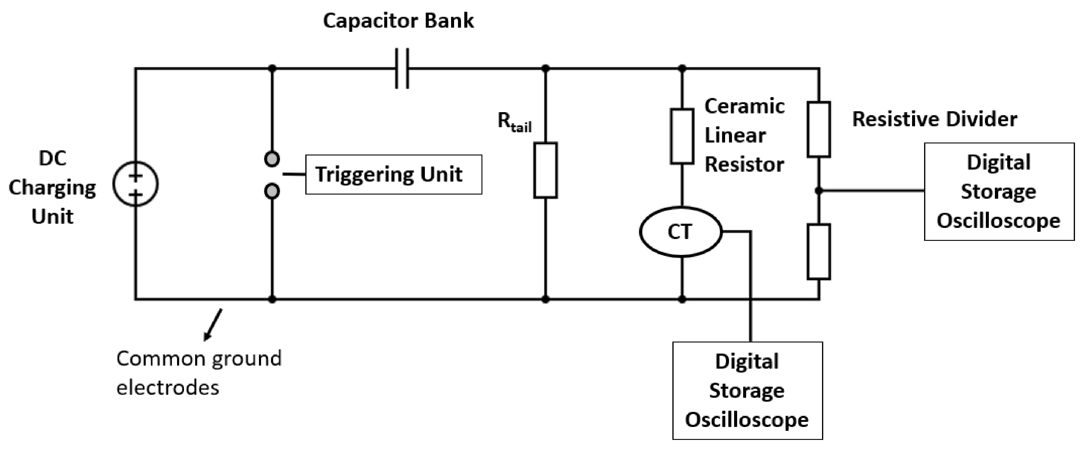
3.1. Linear Resistive Load with a Common Ground Electrode

Impulse tests are performed on a 500 Ω linear test load, with increasing voltage/current magnitudes. Figure 4 shows the voltage and current waveforms at a charging voltage of 100 kV. Similar waveshapes are observed at different voltage/current magnitudes. It is observed from the figure that the voltage and current rise and discharged times occurred at the same time, indicating the linear resistive load. Furthermore, longer discharge times are seen for voltage and current waveshapes, within the 1500 μs to 2000 μs range, due to a linear test load, which normally takes a longer discharge time. Similarly, in the literature [16], when the linear resistive load is simulated with PSPICE simulation, longer discharge times for the voltage and current waveshapes are seen, in comparison to the test load of non-linear. In this study, the discharged times are also found to be dependent on the voltage/current magnitudes, where faster discharged times at higher voltage/current magnitudes are observed, compared to those at lower magnitudes, as shown in Figure 5. This shows that, despite the test load being a linear resistive load, which likely has the same characteristics at various voltage levels, the discharge times are found to occur at a faster time at a higher voltage/current. This observation could be caused by a higher thermal heating process in the linear resistor at higher voltage/current magnitudes, which provides more conduction in the resistor at higher magnitudes of current.
From the voltage and current waveshapes, the resistance values are obtained for all of the voltage/current levels, by dividing the peak voltage with the peak current. The resistance versus peak current is then plotted (see Figure 6). It is observed from the figure that the value of a linear resistor, under a high impulse condition, is approximately 430 Ω, which is 14% lower than that measured at low magnitudes of voltage and current, and the value mentioned in the data sheet by the manufacturer. A lower value of a linear resistor under high-impulse conditions is also seen in previously published work before [17]. This again may be caused by the heating process in the linear resistor, which may have increased the conduction, hence reduced the resistance value.

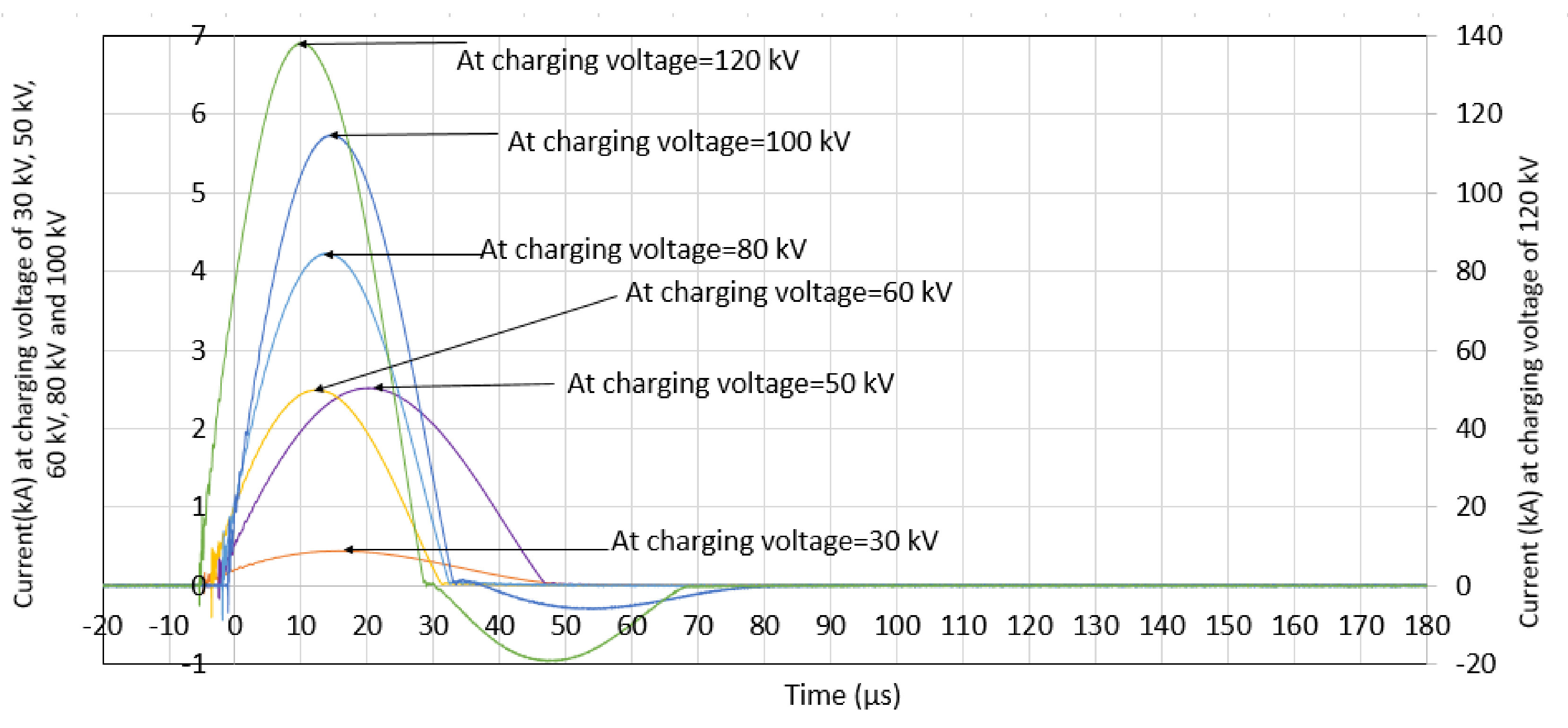
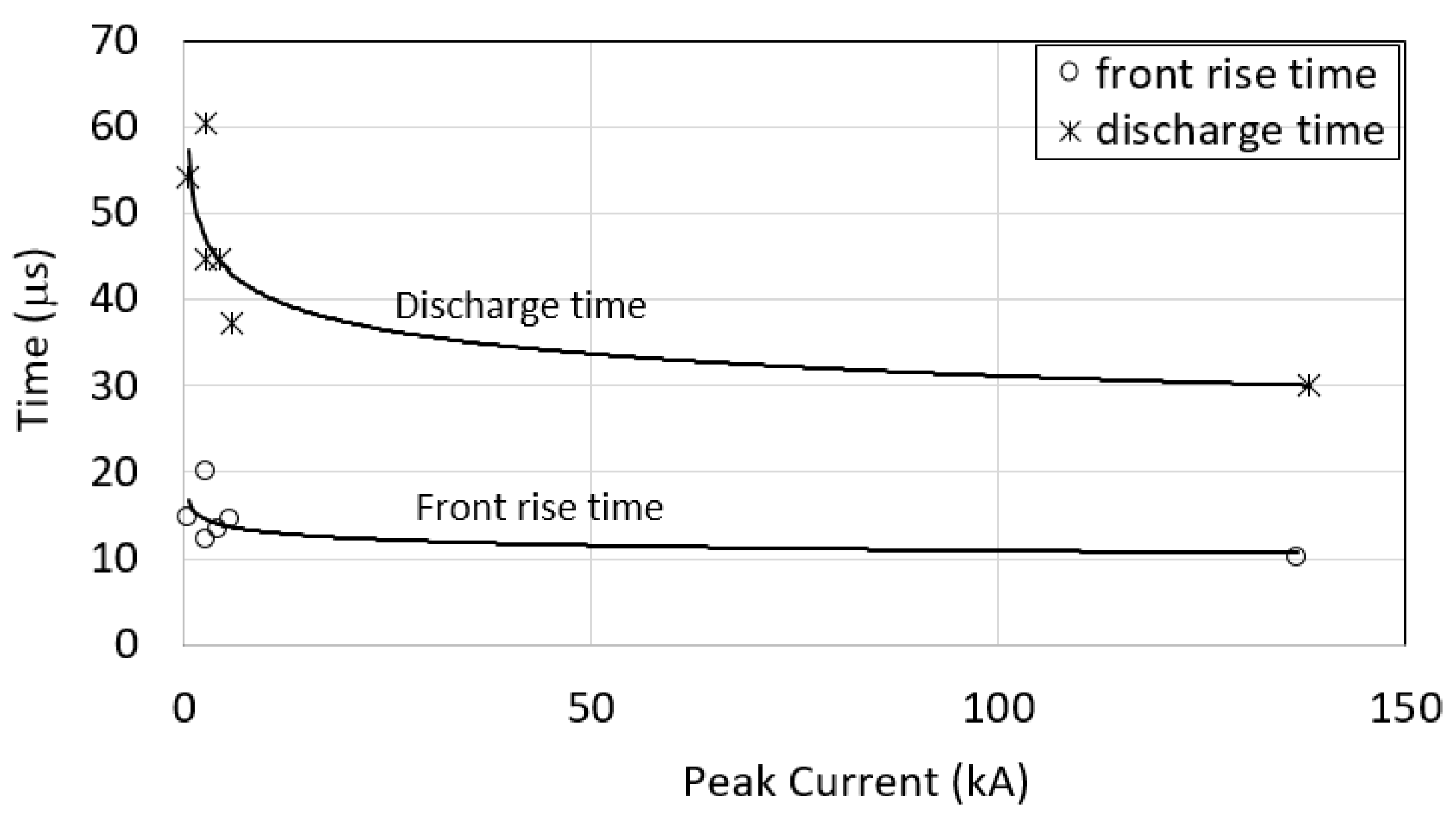
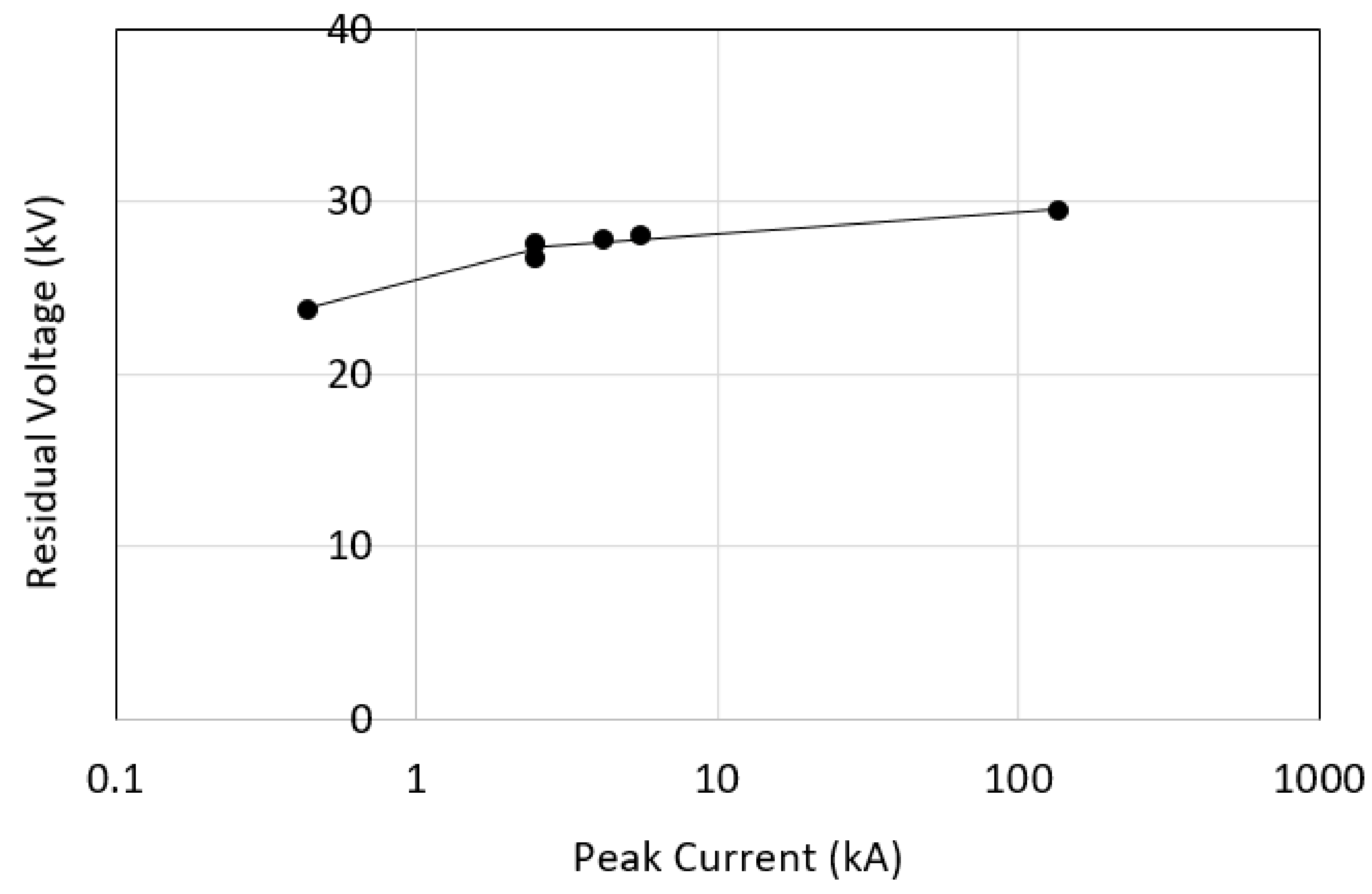
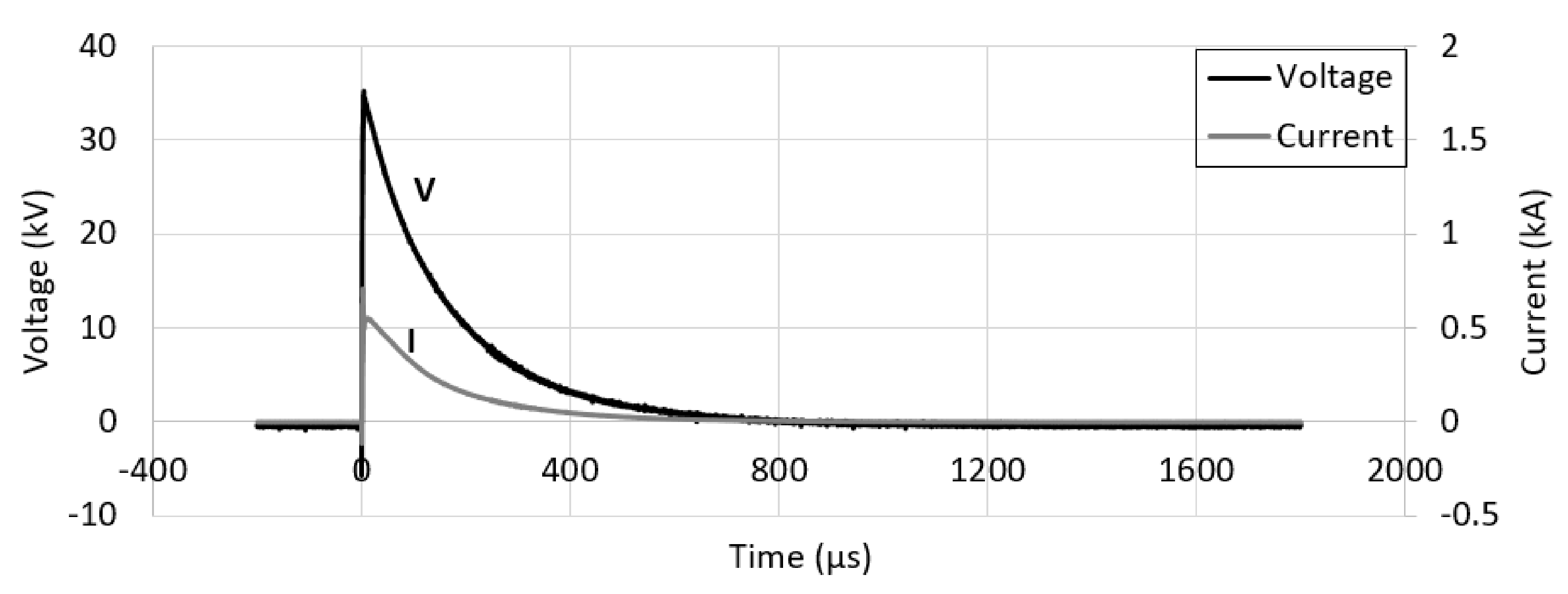
3.2. Surge Arrester with a Common Ground Electrode

Figure 7 shows the typical voltage and current wave shapes at a charging voltage of 30 kV, indicating a low conduction regime of the surge arrester. At a charging voltage of 50 kV and higher, it is observed that the magnitudes of the current become apparently high due to the residual voltage that has been reached in the surge arrester, as shown in Figure 8. The time to the peak current or the front rise times are seen to have occurred faster at all of the current levels, as reflected in Figure 9, and it can also be seen that these front rise times are dependent on the current magnitudes. The variation in these front rise times with increasing current magnitudes is plotted in Figure 10, and it is found that the higher the current magnitudes, the faster the discharge times of current are, where the front rise time decreases from around 20 μs at 2.5 kA to 10 μs at 138.2 kA. These trends are also seen in many publications [7,8,9], where the higher the conduction regime, the faster the front rise and decay times are. This was suggested in [7], as due to a breakdown of the intergranular layers, there were more current paths and conduction through the ZnO surge arrester at high magnitudes of current. On the other hand, a slower front rise time at low current magnitudes may be caused by high impedance of the surge arrester, as mentioned in [7,18]. This is also evident from the discharge time of the current, which it is noted from Figure 10; it can also be noted that there is a slower discharge time at low magnitudes of current and a faster discharge time as the current magnitudes are increased.
It is observed that at all of the voltage/current levels, the current trace discharged at a faster time than the voltage. This could be due to the non-linearity of the surge arrester, in combination with the inductive effect. This observation is similar to that presented in [7,8,9,17]. Metwally [17] noticed that, at all of the stages of the impulse generator, the current traces discharged at faster times than the voltage traces, where these voltage measurements were obtained with a resistive/capacitive probe, capacitive divider and D-dot probe. Since a similar observation was observed in this present study as a previously published study [7,8,9,17], in which the voltage traces were discharged at later times than the current traces, it can be concluded that the measurement used in this paper is reasonably acceptable.
Another notable observation in these measurements is that the voltage traces at all of the voltage levels have initial oscillations. These initial oscillations have been suggested in several studies [7,17] due to a few factors, among which are a combination of inductive effects in the test circuit and capacitive effects of the surge arrester [7], the rate of front current rise times, where higher oscillations are seen for steeper fronted current waves [19]. Several methods have also been proposed in the literature in reducing these initial oscillations in the measurement of the surge arrester, such as using a D-dot probe [7,17], in comparison to other to other commercial voltage dividers. Furthermore, the test arrangement adopted in this study involved experimental work at a field site, with the surge arrester placed a distance away from the divider and the other equipment. Therefore, it can be expected that self and mutual inductance would be present in the test circuit, which, with a combination of the capacitive component of the surge arrester, could contribute to these initial oscillations. However, these initial oscillations and ways to eliminate these effects are beyond the scope of this paper. The same test equipment is used throughout the test in order to provide a direct comparison and consistency in the measurement for the test on the surge arrester with various ground electrodes.
From the voltage and current wave shapes, the voltage–current curve is plotted in Figure 11. For the current magnitudes below 5 kA, small variations in the current magnitudes are seen, as the magnitudes of the charging voltages are increased. As the voltage magnitudes are gradually increased, much higher current magnitudes are obtained, indicating a low impedance of the surge arrester and more current paths at a high conduction regime, allowing a large current to flow through it. It can be seen that for a change in current from 440 A to 136 kA, the voltage increase at the terminal of the surge arrester is small, only 25%, which shows that a large amount of energy is dissipated effectively to the ground through the surge arrester.

3.3. Ground Electrodes

The experimental results on ground electrode tests of the same configurations used in this study have been presented in a separate paper [14,15]. Figure 12 shows the voltage and current wave shapes of a single rod, at a charging voltage of 30 kV. For other ground electrodes and at different levels of voltage/current, similar voltage and current wave shapes are seen. It is found that the voltage rise times are similar to the current rise times. Noticeably, the discharge times for the voltage occurred at the same time as the current traces. This is different than what is seen for the surge arrester, presented in Figure 8, whereby the current traces discharged at faster times than the voltage traces. In this paper, it is also observed that there is no initial oscillation on the voltage trace, which is different than that presented in Figure 8 for the surge arrester. The front rise times and discharge times occurred at the same time for the voltage and current traces, and no initial oscillations are found in the voltage trace, possibly caused by the resistive behavior of the ground electrode.
The test results also show that the front rise times are independent of the current magnitudes and the ground electrodes, with approximately 10 μs, as shown in Figure 13. Inconsistencies in the front rise times are also observed, which could be caused by a non-uniform rate of soil conduction. This is different than that of the surge arrester, whereby the front rise time decreases with the increasing current magnitudes, as presented earlier in Figure 7, which is possibly as a result of more consistencies in the ZnO material, in terms of conduction, in comparison to the soil. On the other hand, for the discharge times it is observed that faster discharge times are seen at higher magnitudes of current (see Figure 14). As described in much published work [14,15,16,20], an ionization process could occur in soil when the grounding systems are subjected to fast transients and high magnitudes of current, which result in non-linearity in the ground electrodes. Due to a larger formation of an ionization zone that surrounds the ground electrodes at high current magnitudes, better conduction is expected in the soil at high magnitudes of current, which gives a faster discharge time at high magnitudes of current than at low current magnitudes. Furthermore, Figure 14 shows that the discharge time is the slowest for the ground electrode with a high RDC (one-rod), and the ring electrode has the fastest discharge time. This is caused by a better conduction of the ground electrodes with a low RDC, allowing larger current magnitudes to be discharged at a faster time.
In most publications [14,15,16], impulse resistance versus current magnitudes are plotted to show the degree of non-linearity of soil under various conditions. However, in this paper, voltage–current characteristics for various ground electrodes are presented in Figure 15 to allow a comparison to be conducted between the ground electrodes and the surge arrester later on. It is seen that the voltage–current curves are increasing slowly, dissimilar to that presented for the surge arrester connected to a common ground in Figure 11, with an apparent increase in the current magnitudes. Another notable observation is that the voltage–current curves are the highest for the single rod, with the highest RDC, indicating a dangerous condition to the system and other equipment since less energy has been discharged to the ground. The slope of the voltage–current curve is the lowest for the ring electrode, and the slopes become more notable for the ground electrode with a high RDC. It is observed that the slope is 29.7, 21.3, 16.5 and 7.4, respectively, for the single rod, 2-rod, 3-rod and ring electrode. These results are further analyzed in the next section of the paper for the performance of the surge arrester with these ground electrodes.

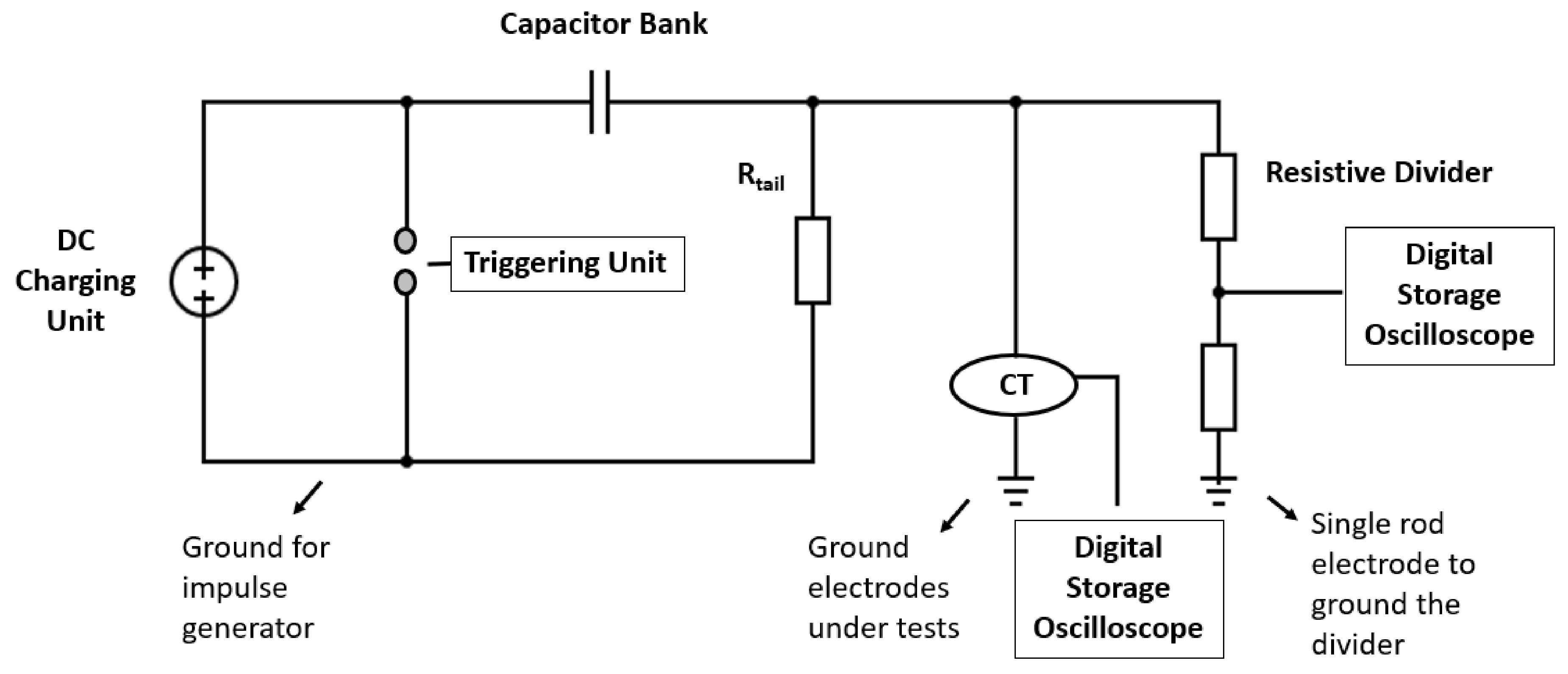
3.4. Linear Resistive Load with 2-rod Electrodes

The studies performed in this work are to determine the characteristics of a surge arrester with various ground electrodes. In order to find out the effectiveness of the experimental set up and test measurements, the tests are first performed on a linear electrode with one of the ground electrodes. In this case, the 2-rod electrodes with the RDC value of 44.8 Ω were used. The rectangular grid that is used as a common ground in Section 2.1, with the RDC value of 8 Ω, is used in this test. Figure 16 shows the voltage and current waveshapes of a linear resistive load, placed on the 2-rod electrodes, at a charging voltage of 100 kV. Similar waveshapes are seen in Figure 4 when the impulse tests are carried out on a test load with linear behavior, and a common ground is observed, whereby the front rise and discharge times of the voltage and current waveshapes occurred at the same time. Figure 17 shows the variation in the discharge times with the increasing current, which are found to reduce from approximately 2600 μs at 80 A to 1600 μs at 240 A of the peak current magnitudes. These discharge times are found to be slightly higher than those shown in Figure 10, when a common ground electrode is used for the testing on a linear test load. The slower discharge times for the linear test load with 2-rod electrodes, in comparison to when testing the linear test load with a common ground, could be due to a higher resistance value of the 2-rod electrode, of 44.8 Ω, in comparison to the common grid, of only 8 Ω. Due to a longer cable used in the test arrangement where the 2-rod electrodes are separated from the common ground electrode, this could also be the reason for a longer discharge time.
The resistance value of the linear test load for the various peak current magnitudes is also measured, taken as the voltage at the peak divided by the current value at the peak. It is found to be an average of approximately 420 Ω (see Figure 18), which is close to the resistance value presented earlier, in Figure 6, when the impulse tests are performed on the same linear test load, however with a common ground. A close result between the linear resistive load tested with a common ground and the 2-rod electrodes gives an indication that the test set up and test measurement with separate grounds provides a reliable and valid measurement to characterize the surge arrester with various ground electrodes.

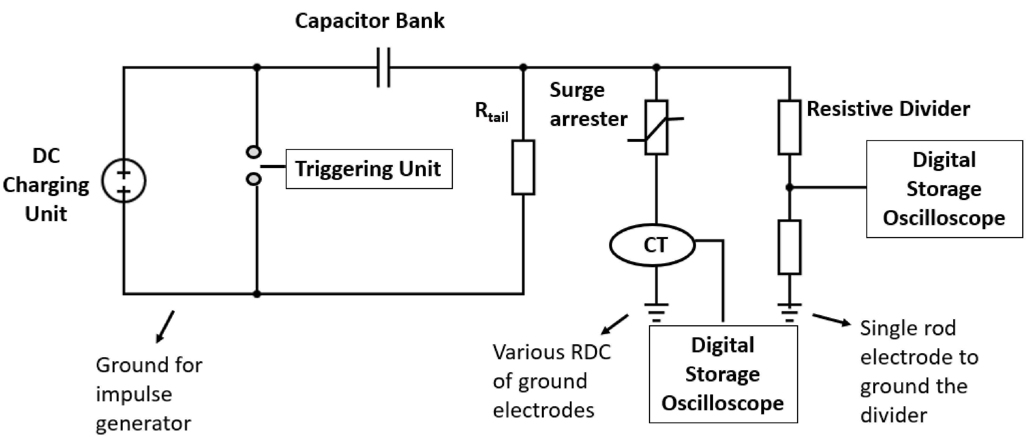
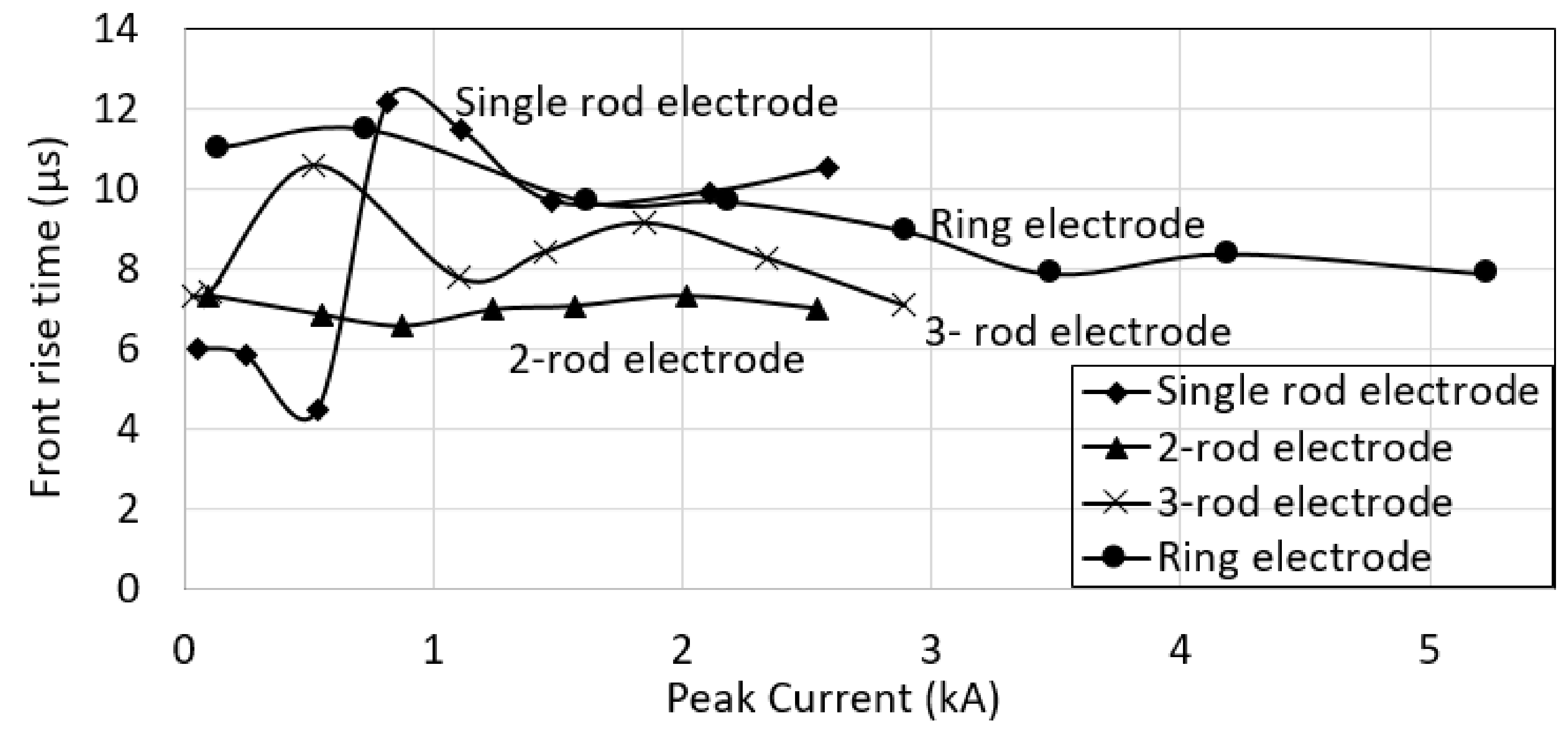
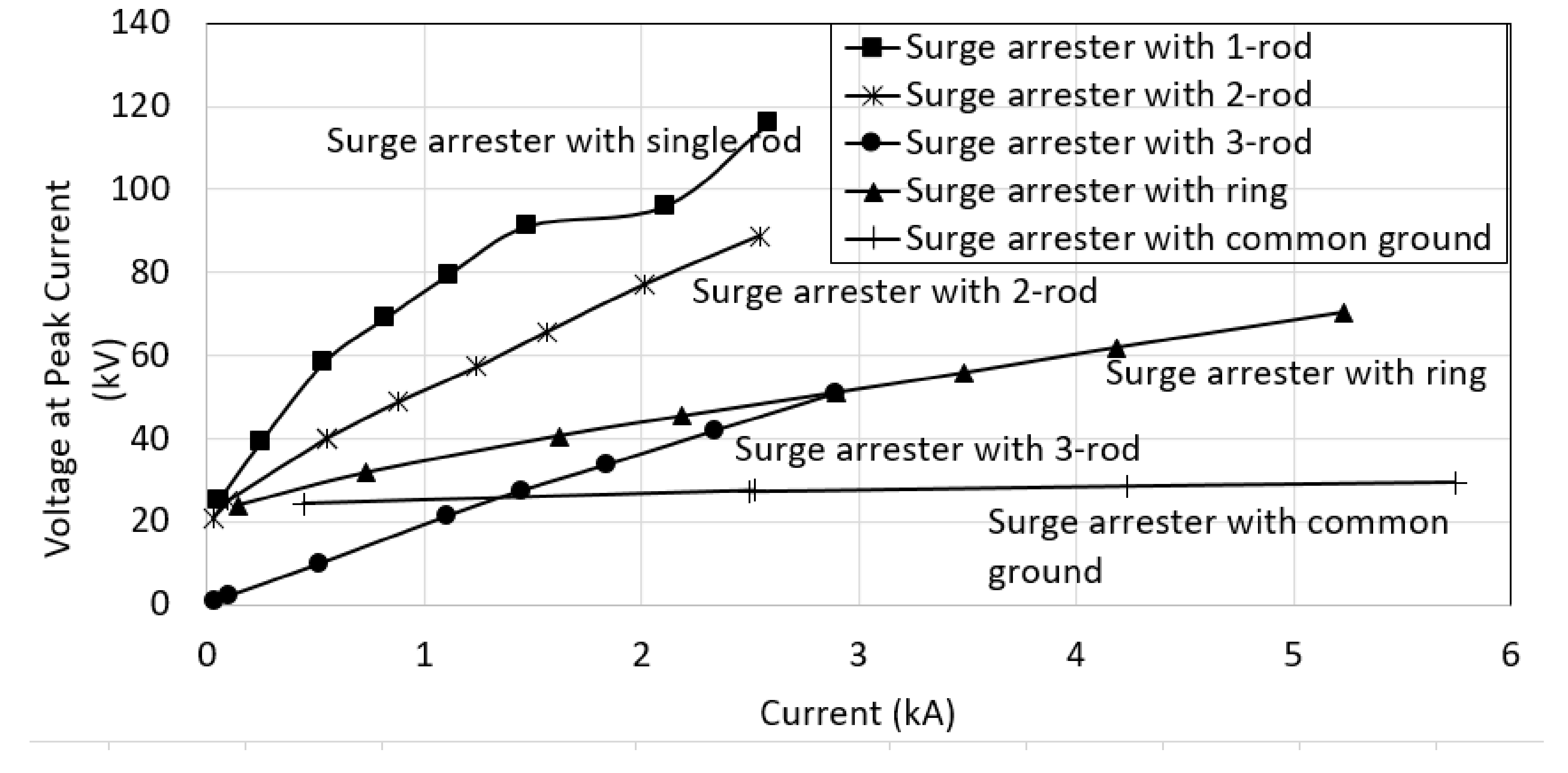
3.5. Surge Arrester with Various Ground Electrodes

In this section, the test results on the surge arrester with increasing charging voltage are presented and compared with those presented in the earlier sections. Figure 19 shows the voltage and current waveshapes of the surge arrester connected to a single-rod electrode at a charging voltage of 80 kV. Similar traces are seen for the surge arrester connected to the 2-rod and ring electrode, whereby the current waveshape discharged before the discharge time of the voltage waveshape. This could be caused by the non-linear elements of the surge arrester and the ground electrodes, and with the presence of inductance in the test circuit. Similar observations are seen when simulation work is done on linear and non-linear test loads by PSPICE, where the current waveshapes are found to discharge at faster times than the voltage waveshapes for the non-linear test load [16]. However, for the surge arrester connected to the 3-rod electrode, it has transpired that the current trace discharged at the same time as the voltage trace (see Figure 20). This shows that the surge arrester connected to the 3-rod electrode has a rather more linear resistive behavior in comparison to the characteristics of the surge arrester connected to the one-rod, two-rod and ring electrodes, which may have more non-linear resistive behavior.
The front rise times of the current traces are found to occur at the same time as the voltage for all of the current magnitudes and test results. These front rise times are plotted with increasing currents in Figure 21, which can be seen to be almost constant with the increasing current magnitudes for the surge arrester connected to all of the ground electrodes, with an approximate average of 10 μs, which is similar to that presented earlier, in Section 3.2, for the ground electrodes without the surge arrester.
A further observation is that the initial oscillations, which are seen when the surge arrester is connected to a common ground, presented in Figure 7 and Figure 8, are not observable in these test results. In Section 3.1, the presence of the initial oscillations on the voltage waveshape could be caused by the combination of the effect of inductance from the test circuit and the capacitive component of the surge arrester. However, in these tests, the test loads now consist of the surge arrester and the ground electrodes. Several studies [7] have shown that the equivalent circuits of the surge arrester can be represented by a pre-dominantly non-linear resistive element at a high conduction current. A similar representation of an equivalent circuit has also been proposed for ground electrodes in previously published work [16]. Thus, a combination of both non-linear elements for both test loads could have contributed to the non-noticeable initial oscillations. It is, however, out of the scope of the present paper to simulate for these equivalent circuits of the combination of surge arrester and test loads at this stage. It is an area worth exploring separately in the future.
The voltage–current curves are also plotted in Figure 22 for the surge arrester connected to different ground electrodes, along with the surge arrester with common ground. Similar to the voltage–current curves in Figure 18, the applied voltage is dependent on the RDC of the ground electrode, and it is found that the one-rod electrode (the highest RDC) has the highest voltage. It is found that the voltage for the ring is higher than the three-rod electrode, despite the RDC for the three-rod being higher than the ring electrode. The slopes of these voltage–current curves are found to be the highest for the ground with RDC, which are 32.7, 26.4, 17.6 and 8.9, respectively, for the one-rod, two-rod, three-rod and ring electrode. It is observed that the voltage–current curves for the surge arrester with the three-rod electrode touched the curve of the surge arrester with the common ground at approximately 1.5 kA. This indicates that the surge arrester is at its expected performance at this current level. However, for the surge arrester to other ground electrodes, a similar voltage–current characteristic is only seen at lower current magnitudes, approximately 300 A for the ring electrode and 100 A for both the single and the two-rod electrodes. This shows that only at a low conduction regime did the surge arrester connect to the various ground electrodes, which functioned similarly to that with common ground electrode. It can also be noticed that the voltage–current curve for the surge arrester connected to the 3-rod electrode is found to be similar to the ground electrode without the surge arrester, seen in Figure 20.

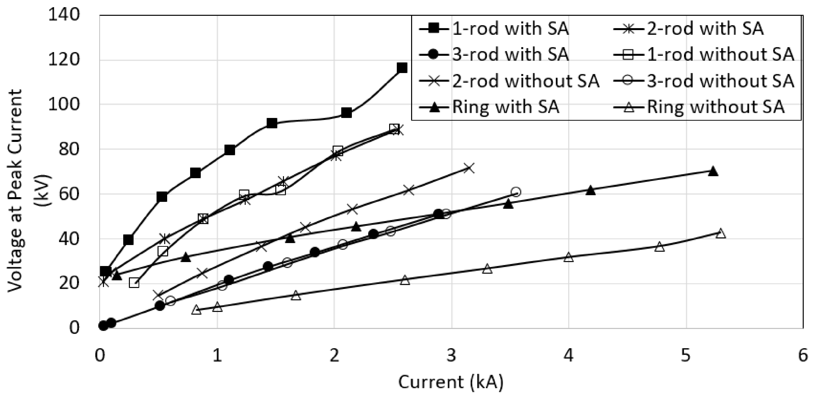
3.6. Comparison between Ground Electrodes with and without Surge Arrester

The tests on the ground electrodes, with and without the surge arrester, revealed that a higher voltage and a larger slope are seen for the ground electrodes with the surge arrester, except for the three-rod electrodes, with the voltage magnitudes at the terminal being close for the ground electrodes with and without the surge arrester (see Figure 23). A higher voltage for the ground with the surge arrester could be an indication that the surge arrester becomes ineffective when placed on the ground electrodes with a high RDC, since most of the energy is at the voltage terminal and is not effectively absorbed by the surge arrester, subsequently dissipated to the ground. This can be a dangerous condition to the systems and other equipment. For the front rise time, close values are obtained for both of the following conditions: ground electrodes with and without a surge arrester, which is around 10 μs. The possible reason for a higher voltage for the ring electrode, than the three-rod electrode, is that the copper mesh connected from one rod to another is present above the ground’s surface rather than installed into the ground. A similar connection is adopted for the two- and three-rod ground rod electrodes; however, less copper mesh is used in comparison to the installation of the ring electrode. It is also found that for the voltage and current traces of the three-rod ground electrode, the discharge times of the voltage occurred at the same time as the voltage, showing the linear resistive behavior, in comparison to other ground electrodes. This could also be the reason for having the same voltage–current curve for the three-rod electrode and the surge arrester connected to the three-rod electrode.
A similar characteristic that is noted from the tests on the ground electrode with the surge arrester is that the discharge time of the current occurred at a faster time than the discharge time of the voltage. This is thought to be caused by the non-linear elements from the surge arrester and the ground electrodes, and the presence of the inductance in the test circuit. No specific measurement is performed on the discharge time of the current for the surge arrester with various ground electrodes in this paper; however, it is observed that the discharge time for the current was approximately 400 μs, which is lower than that presented for the ground electrode without the surge arrester, as presented earlier in Figure 14. As the voltage/current magnitudes were increased, and in the ground electrodes with a lower RDC, faster discharge times were noted. In conclusion, the discharge times of that with the surge arrester are achieved faster, though little difference is seen in terms of its reduced voltage.

4. Discussion

A set of the following five impulse tests are carried out in this study: (i) a linear test load with a common ground electrode, (ii) a surge arrester with a common ground electrode, (iii) various ground electrodes, (iv) a linear resistor with a two-rod electrode, and (v) a surge arrester with various ground electrodes. The experimental test results of a linear test load with a common ground electrode in (i) are found to be similar to that of (iv), indicating that the test set up and measurement adopted to study the characteristics of the surge arrester with various ground electrodes.
Experiments on a surge arrester with a common ground electrode, as mentioned in IEC 60060-1, are presented. The initial oscillations on the voltage traces are quite obvious, and these oscillations occurred at all of the voltage/current levels. The front rise and discharge times of the current traces are found to decrease as the voltage/current magnitudes are increased, possibly caused by more current paths at a high conduction region of the surge arrester. The voltage–current curve indicated that the voltage increases slowly, with an apparent increase in the peak current, indicating good conduction of the surge arrester at high current magnitudes, and most of the energy is dissipated to the ground.
Tests on ground electrodes with various RDC are also performed and the results showed that there are no initial oscillations on the voltage trace. The current front rise and discharge times occur at the same time as the voltage trace and are independent of the ground electrodes. On the other hand, the discharge time is dependent on the RDC of the ground electrodes, whereby the single rod with the highest RDC has the highest discharge time, and the ring electrode with the lowest RDC has the lowest discharge time. Furthermore, the discharge time is found to reduce as the current magnitudes are increased. The voltage–current curves of the ground electrodes without the surge arrester with various RDC values are presented, and found that a single rod (the highest RDC) has the highest voltage, followed by the two, three-rod ground rod electrodes and ring electrodes, indicating a dangerous condition for the ground electrode with a high RDC.
The voltage–current curves are found to have higher slopes with higher voltage magnitudes when the ground electrodes are connected to the surge arrester. This could be attributed to the malfunction of the surge arrester when the ground electrodes are of high RDC. The surge arrester connected with the three-rod ground electrode was found to have similar conduction for the current at 300 A to that of the surge arrester connected to common ground. Again, there are no initial oscillations on the voltage trace seen during these tests. The current traces are found to discharge at faster times than the voltage traces, indicating the non-linearity of the surge arrester and the ground systems.
All of these results present that it is necessary to consider the ground electrode and its RDC in the installation of the surge arrester. The results also portray that the ground electrode of 17 Ω is still inadequate to reduce the voltage at the systems terminal and allow the energy to be dissipated to the ground. The study suggests that further analysis needs to be undertaken in order to determine the suitability of the ground electrode as well as the connection of the copper mesh buried into the ground, and relating it to the RDC values of ground electrodes to be used along with the surge arrester.

Author Contributions

Conceptualization, N.M.N.; methodology, N.M.N.; formal analysis, N.M.N.; investigation, H.H.H.-D. and N.M.N.; data curation, N.M.N.; writing—original draft preparation, H.H.H.-D.; writing—review and editing, N.M.N.; supervision, N.M.N. All authors have read and agreed to the published version of the manuscript.

Funding

Please add: This project is financially supported by Telekom Malaysia Research and Development (TMR&D) with the grant number MMUE 190085.

Institutional Review Board Statement

Not applicable.

Informed Consent Statement

Not applicable.

Data Availability Statement

Not applicable.

Conflicts of Interest

The authors declare no conflict of interest.

References

  1. IEEE Std C62. 22-2012. IEEE Guide for the Application of Metal-Oxide Surge Arresters for Alternating-Current Systems; IEEE: New York, NY, USA, 2013. [Google Scholar]
  2. PC62.11/D6.0 Sep 2019. IEEE Draft Standard for Metal-Oxide Surge Arresters for AC Power Circuits (>1 kV); IEEE: New York, NY, USA, 2020. [Google Scholar]
  3. IEC 60099-3: 1990. Artificial Pollution Testing of Surge Arrester; IEC: Geneva, Switzerland, 1991. [Google Scholar]
  4. IEC 60099-4:2014. Surge Arresters-Part 4: Metal-Oxide Surge Arresters without Gaps for a.c. Systems; IEC: Geneva, Switzerland, 2014. [Google Scholar]
  5. Metwally, I.A. Performance of Distribution-class Surge Arresters under Dry and Artificial Pollution Conditions. Electr. Eng. 2010, 93, 55–62. [Google Scholar] [CrossRef]
  6. Rodríguez, M.; Francisco, R. Experimental Study of Surge Arrester Ageing using a High Impedance Current Source. In Proceedings of the 33th of IEEE International Conference on Lightning Protection (ICLP), Estoril, Portugal, 25–30 September 2016. [Google Scholar]
  7. Haddad, A.; Naylor, P. Dynamic Impulse Conduction in ZnO Arrester. In Proceedings of the 11th International Symposium on High Voltage Engineering, London, UK, 23–27 August 1999. [Google Scholar]
  8. Fang, Z.; Wang, B.; Lu, J.; Jiang, Z. Study on Impulse Breakdown Characteristics of Internal-Gap Lightning Protection Device Applied to 35 kV Distribution Line. Energies 2018, 11, 1758. [Google Scholar] [CrossRef] [Green Version]
  9. Latiff, N.; Illias, H.; Bakar, H.A.; Dabbak, S. Measurement and Modelling of Leakage Current Behaviour in ZnO Surge Arresters under Various Applied Voltage Amplitudes and Pollution Conditions. Energies 2018, 11, 875. [Google Scholar] [CrossRef] [Green Version]
  10. Christodoulou, C.; Ekonomou, L.; Papanikolaou, N.; Gonos, I. Effect of the Grounding Resistance to the Behaviour of High-voltage Transmission Lines’ Surge Arresters. IET Sci. Meas. Technol. 2014, 8, 470–478. [Google Scholar] [CrossRef]
  11. Hidaka, T.; Ishimoto, K.; Asakawa, A.; Shiota, K. Relationship between Grounding Resistance Connected to Surge Arresters and Lightning Surge Behavior Observed in Low-Voltage Equipment. In Proceedings of the International Symposium on Lightning Protection (XII SIPDA), Belo Horizonte, Brazil, 7–11 October 2013. [Google Scholar]
  12. Mancao, R.T.; Burke, J.T.; Myers, A. The Effect of Distribution System Grounding on MOV Selection. IEEE Trans. Power Deliv. 1993, 8, 139–145. [Google Scholar] [CrossRef]
  13. IEC 60060-1. High-Voltage Test Techniques-Part 1; IEC: Geneva, Switzerland, 2010. [Google Scholar]
  14. Abdul Ali, A.; Ahmad, N.; Mohamad Nor, N.; Idris, N.; Hanaffi, F. Investigations on the Performance of Grounding Device with Spike Rods (GDSR) with the Effects of Soil Resistivity and Configurations. Energies 2020, 13, 3538. [Google Scholar] [CrossRef]
  15. Abdul Ali, A.; Ahmad, N.; Mohamad Nor, N.; Reffin, M.; Syed Abdullah, S. Investigations on the Performance of a New Grounding Device with Spike Rods under High Magnitude Current Conditions. Energies 2019, 12, 1138. [Google Scholar] [CrossRef] [Green Version]
  16. Mohamad Nor, N. Investigations of Soil Characterisation under High Impulse Currents. Ph.D. Thesis, University of Wales, College of Cardiff, Cardiff, Wales, 2001. [Google Scholar]
  17. Metwally, I.A. D-Dot Probe for Fast-Front High-Voltage Measurement. IEEE Trans. Instrum. Meas. 2010, 59, 2211–2219. [Google Scholar] [CrossRef]
  18. Naidu, M.S.; Kamaraju, V. High-Voltage Engineering, 5th ed.; Mc Graw Hill Education: New Delhi, India, 2013. [Google Scholar]
  19. Dang, C.; Parnell, T.M.; Price, P.J. The Response of Metal Oxide Surge Arresters to Steep Fronted Current Impulses. IEEE Trans. Power Deliv. 1986, 1, 167–183. [Google Scholar] [CrossRef]
  20. Abdul Ali, A.; Mohamad Nor, N. On the Characterisations of the Impulse Breakdown in High Resistivity Soils by Field Testing. Energies 2021, 14, 2401. [Google Scholar] [CrossRef]
Figure 1. Test arrangement for impulse tests on a linear test load with a common ground.
Energies 14 03382 g001
Figure 2. Test arrangement for impulse tests on ground electrode without the surge arrester.
Energies 14 03382 g002
Figure 3. Test arrangement for impulse tests on test load with various ground electrodes.
Energies 14 03382 g003
Figure 4. Voltage and current wave shapes for a linear resistive load at charging voltage of 100 kV.
Energies 14 03382 g004
Figure 5. Discharged time with increasing current magnitudes for a linear resistive load.
Energies 14 03382 g005
Figure 6. Impulse resistance versus peak current for a linear resistive load with a common ground.
Energies 14 03382 g006
Figure 7. Voltage and current wave shapes for surge arrester with a common ground electrode, at charging voltage of 30 kV.
Energies 14 03382 g007
Figure 8. Voltage and current wave shapes for surge arrester with a common ground electrode, at charging voltage of 50 kV.
Energies 14 03382 g008
Figure 9. Voltage and current wave shapes for surge arrester with a common ground electrode, at charging voltage of 30 kV.
Energies 14 03382 g009
Figure 10. Current front rise and discharged times for surge arrester with increasing current magnitudes.
Energies 14 03382 g010
Figure 11. Voltage–current characteristics of surge arrester with common ground electrodes.
Energies 14 03382 g011
Figure 12. Voltage and current waveshapes a single-rod ground electrode.
Energies 14 03382 g012
Figure 13. Front rise times versus peak currents for various ground electrodes.
Energies 14 03382 g013
Figure 14. Discharged times versus peak currents for various ground electrodes.
Energies 14 03382 g014
Figure 15. Voltage–current characteristics various ground electrodes without the surge arrester.
Energies 14 03382 g015
Figure 16. Voltage and current traces of a linear resistive load with two-rod electrodes as its ground electrodes.
Energies 14 03382 g016
Figure 17. Variation in discharged times with increasing current magnitudes of a resistive linear test load.
Energies 14 03382 g017
Figure 18. Impulse impedance versus peak current for a linear resistive load with 3-rod electrodes.
Energies 14 03382 g018
Figure 19. Voltage and current waveshapes of surge arrester connected to a single-rod ground electrode at charging voltage of 30 kV.
Energies 14 03382 g019
Figure 20. Voltage and current waveshapes for surge arrester connected to 3-rod electrode at charging voltage of 80 kV.
Energies 14 03382 g020
Figure 21. Front rise times versus peak currents for surge arrester connected to various ground electrodes.
Energies 14 03382 g021
Figure 22. Voltage–current characteristics of surge arrester connected to various ground electrodes.
Energies 14 03382 g022
Figure 23. Voltage–current characteristics of ground electrodes with and without the surge arrester.
Energies 14 03382 g023
Table 1. Drawings of ground electrodes and its corresponding RDC values.
Energies 14 03382 i001
Tested electrode, a single rod, RDC = 104.4 Ω
Energies 14 03382 i002
Tested electrode, 2-rod electrodes, RDC = 44.8 Ω
Energies 14 03382 i003
Tested electrode, 3-rod electrodes, RDC = 28.5 Ω
Energies 14 03382 i004
Tested electrode, ring electrode, RDC = 17.2 Ω
Energies 14 03382 i005
Remote earth, a grid, RDC = 8 Ω
Publisher’s Note: MDPI stays neutral with regard to jurisdictional claims in published maps and institutional affiliations.

